EP0135196A2 - Mobile radio communication system - Google Patents
Mobile radio communication system Download PDFInfo
- Publication number
- EP0135196A2 EP0135196A2 EP84110997A EP84110997A EP0135196A2 EP 0135196 A2 EP0135196 A2 EP 0135196A2 EP 84110997 A EP84110997 A EP 84110997A EP 84110997 A EP84110997 A EP 84110997A EP 0135196 A2 EP0135196 A2 EP 0135196A2
- Authority
- EP
- European Patent Office
- Prior art keywords
- rate
- mobile station
- mobile
- communication system
- radio communication
- Prior art date
- Legal status (The legal status is an assumption and is not a legal conclusion. Google has not performed a legal analysis and makes no representation as to the accuracy of the status listed.)
- Granted
Links
- 238000004891 communication Methods 0.000 title claims abstract description 16
- 230000005540 biological transmission Effects 0.000 claims description 16
- 230000004044 response Effects 0.000 claims description 6
- 239000004065 semiconductor Substances 0.000 claims description 5
- 238000010586 diagram Methods 0.000 description 3
- 238000000034 method Methods 0.000 description 3
- 238000012986 modification Methods 0.000 description 3
- 230000004048 modification Effects 0.000 description 3
- 238000001514 detection method Methods 0.000 description 2
- 102000006479 Heterogeneous-Nuclear Ribonucleoproteins Human genes 0.000 description 1
- 108010019372 Heterogeneous-Nuclear Ribonucleoproteins Proteins 0.000 description 1
- 238000006243 chemical reaction Methods 0.000 description 1
- 238000010276 construction Methods 0.000 description 1
- 238000010295 mobile communication Methods 0.000 description 1
Images


Classifications
-
- H—ELECTRICITY
- H04—ELECTRIC COMMUNICATION TECHNIQUE
- H04W—WIRELESS COMMUNICATION NETWORKS
- H04W4/00—Services specially adapted for wireless communication networks; Facilities therefor
- H04W4/24—Accounting or billing
-
- H—ELECTRICITY
- H04—ELECTRIC COMMUNICATION TECHNIQUE
- H04M—TELEPHONIC COMMUNICATION
- H04M15/00—Arrangements for metering, time-control or time indication ; Metering, charging or billing arrangements for voice wireline or wireless communications, e.g. VoIP
- H04M15/28—Arrangements for metering, time-control or time indication ; Metering, charging or billing arrangements for voice wireline or wireless communications, e.g. VoIP with meter at substation or with calculation of charges at terminal
-
- H—ELECTRICITY
- H04—ELECTRIC COMMUNICATION TECHNIQUE
- H04M—TELEPHONIC COMMUNICATION
- H04M17/00—Prepayment of wireline communication systems, wireless communication systems or telephone systems
-
- H—ELECTRICITY
- H04—ELECTRIC COMMUNICATION TECHNIQUE
- H04M—TELEPHONIC COMMUNICATION
- H04M2215/00—Metering arrangements; Time controlling arrangements; Time indicating arrangements
- H04M2215/32—Involving wireless systems
Abstract
Description
- This invention relates to a mobile radio communication system comprising a fixed station connected to a subscriber's line of a telephone exchange and a mobile station linked with the fixed station through a radio channel, and more particularly to a mobile radio communication system having an improved charging system.
- As one of radio telephone systems, there is a cordless telephone system in which a cordless telephone set is linked with only one fixed station through a radio channel. Therefore, its service area is extremely small. For this reason, the cordless telephone set can not be used on the outside of the area, so that a user must use a nearby public telephone set.
- Although a radio paging (pocket bell system) has a wide service area, this system is used for only calling, so that the user must also use a public telephone set at the time of origination.
- A wide area radio telephone system can solve these problems and it is desirable to provide a wider area radio telephone system which can ensure origination and termination at any place and at any time. Such a system, however, necessarily uses a telephone line and faces an important problem in charging rate at the time of origination from a mobile station or a mobile set.
- It is an object of this invention to provide a mobile radio communication system capable of ensuring a telephoe service in a wide area with a relatively small number of radio channels by providing rate charging means for a mobile station which can be connected to any fixed station installed at a terminal end of a telephone network.
- Another object of this invention is to provide a novel mobile radio communication system capable of increasing the service area of a mobile station by permitting a mobile station to be connected to any fixed station connected to a public telephone line and to a specific fixed station connected to an ordinary telephone line.
- According to the present invention, in a mobile radio communication system comprising a plurality of fixed stations respectively connected to a plurality of subscriber's lines extending from a telephone exchange, and a plurality of mobile stations linked with the fixed stations through radio channels, each of the mobile stations effecting speech via one of the fixed stations, . the system comprises means provided for each fixed station for transmitting-rate charging information from the telephone exchange to a mobile station under speech, and rate collecting means provided for each mobile station and being responsive to the rate charging information to vary its content.
- In the accompanying drawings;
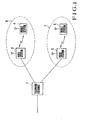
- Fig. 1 is a block diagram showing a system to which the mobile radio communicaton system of this invention is applicable;
- Fig. 2 is a block diagram showing an embodiment of a mobile station and a fixed station (or fixed radio station) employed in the system of this ivnention;
- Fig. 3 is a flow chart for explaining the operation of the apparatus shown in Fig. 2;
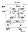
- Fig. 4 is a block diagram showing-a modification of the mobile station shown in Fig. 2;
- Fig. 5 is a diagramatic representation showing another system to which the mobile radio communication system of this invention is applicable;
- Fig. 6A shows one example of a rate charging unit; and
- Fig. 6B shows another example of the rate charging unit.
- The invention will now be described in detail with reference to the accompanying drawings.
- The mobile radio communcation system shown in Fig. 1 comprises a
telephone exchange 1,fixed stations 2 and 3, andmobile stations Reference numerals fixed stations 2 and 3, respectively. - When the
mobile station 4 originates, an origination connection is made to the fixed station 2, since themobile station 4 is in the service area of the fixed station 2, to transmit a rate charging signal to the fixed station 2, whereby themobile station 4 collects the rate to permit talking. When themobile station 4 moves to a position of amobile station 5 and then originates, an origination connection is made to thefixed station 3 since themobile station 5 is in the service area of thefixed station 3. Then, thefixed station 3 transmits to the mobile station a rate charging signal in order for themobile station 5 to collect the rate, thus permitting talking. - The mobile station and the fixed station as operable in the system of Fig. 1 are exemplified as a
mobile station 10 and afixed station 50 in Fig. 2 in accordance with teachings of the present invention. Themobile station 10 comprises a transmittingsection 10a, a receivingsection 10b, acontrol section 10c, and arate charging section 10d. The transmittingsection 10a includes a telephone transmitter (microphone) 11, anamplifier 12 amplifying a voice signal from thetransmitter 11, a transmissionsignal switching circuit 13 connected to the output of theamplifier 12 for switching a transmission signal to atransmitter 14 which converts the transmission signal from theswitching circuit 13 into a radio frequency signal, and a transmittingantenna 15 for radiating the output of thetransmitter 14 into air. - The
receiving section 10b includes areceiver 24 for receiving and demodulating a radio frequency signal from a receivingantenna 25, a receptionsignal switching circuit 23 connected to receive the demodulated output of thereceiver 24 for passing only a voice signal, and anamplifier 22 for amplifying the voice signal outputted from theswitching circuit 23 and driving atelephone receiver 21. - The
control section 10c includes acontrol signal detector 31, a transmissioncontrol signal generator 32, ahook switch 34, and acontrol circuit 35. Thedetector 31 receives the demodulated output of thereceiver 24 and detects a control signal contained in the demodulated signal and sent from the fixed station. Thecontrol circuit 35 decodes the output signals from thedetector 31 and thehook switch 34 to control theswitching circuits generator 32 and arate charging circuit 33. Thegenerator 32 is responsive to a signal from thecontrol circuit 35 and generates a transmission control signal which is sent to theswitching circuit 13. - The
rate charging section 10c includes therate charging circuit 33 connected to thecontrol circuit 35 and containing an amount of money information representing the rate. - The
switching circuit 13 responds to a switch control signal from thecontrol circuit 35 and supplies either the voice signal (information signal) from theamplifier 12 or the transmission control signal from thegenerator 32, to thetransmitter 14. Theswitching circuit 23 prevents the passage of the other signal than the voice signal to theamplifier 22 in response to a rate charging signal or other control signals from thecontrol circuit 35. - The
fixed station 50 comprises a transmittingsection 50a, a receivingsection 50b, acontrol section 50c and aline connection section 50d. - The
line connection section 50d includesloop switch 72 connected to a telephone subscriber'sline 73 from the telephone exchange, and ahybrid network 71 having two wire/four wire conversion performance. - The transmitting
section 50a includes anamplifier 54 connected to thenetrwork 71 for amplifying the voice signal from the subscriber'sline 73 and outputted from thenetwork 71, a transmissionsignal switching circut 53 for switching the output of acontrol signal generator 75, atransmitter 52 for connecting the output of theswitching circuit 53 into a radio frequency signal, and atransmission antenna 51 for radiating into air the output of thetransmitter 52. - The
receiving section 50b includes areceiver 62 for receiving and demodulating the radio frequency signal from a receivingantenna 61, a receptionsignal switching circuit 63 connected to receive the demodulated output of thereceiver 62 for passing only the voice signal, and anamplifier 64 amplifying the output signal of the receptionsignal switching circuit 63 for supplying an amplified signal to thenetwork 71. - The
control section 50c includes acontrol signal detector 74 connected to recieve the demodulated output of thereceiver 62 for detecting a control signal from the mobile station, a ratecharging signal detector 76 connected to the subscriber'sline 73 for detecting a rate charging signal sent from the telephone exchange, acontrol circuit 77 which is responsive to signals sent from the ratecharging signal detector 76 and thecontrol signal detector 74 for controlling theswitching circuits loop switch 72 and thegenerator 75. Thegenerator 75 is responsive to a signal from thecontrol circuit 77 and generates a transmission control signal sent to the transmissionsignal switching circuit 53. - The
switching circuits circuits - The speech operation of the mobile station and the fixed station having construcions as described above will now be described.
- To originate at the
mobile staton 10, thehook switch 34 is first operated. In response to a signal from thehook switch 34, thecontrol circuit 35 is started to control thegenerator 32 and theswitching circuit 13 so as to cause thetransmitter 14 to send an origination signal to thefixed station 50. The originating signal is received by thereceiver 62 of thefixed station 50, and this signal is detected bydetector 74 and then inputted to thecontrol circuit 77. In response to the origination signal from themobile station 10, thecontrol circuit 77 operates theloop switch 72 so as to send the origination signal to the telephone exchange to start speech. - The rate charging operation characterizing the invention will be described with reference to the flow chart shown in Fig. 3.
- When speech is started, a rate charging signal corresponding to a speech rate is sent from the telephone exchange through the subscriber's
line 73. Generally, the rate charging signal is formed by inverting the polarity of a signal on the subscriber's line. The rate charging signal is detected by the ratecharging signal detector 76 at step Sl and applied to thecontrol circuit 77. In response to the signal from the ratecharging signal detector 76, thecontrol circuit 77 drives thecontrol signal generator 75 and switches theswitching circuit 53 so that the output signal of thegenerator 75 is supplied to thetransmitter 52, thereby causing thetransmitter 52 to send a rate charging signal to themobile station 10 at step S2. At step S5, themobile station 10 receives the rate charging signal from thefixed station 50 and the rate charging signal is detected by thecontrol signal detector 31 and supplied to thecontrol circuit 35. At step S6, thecontrol circuit 35 inputted with the rate charging signal subtracts an amount corresponding to the rate charging signal from the amount of money information of therate charging circuit 33, thereby collecting the rate. Where the money information has-been reduced to a value at which substraction is no more possible, the speech must be interruptted since it is impossible to collect the rate any more. When this state is detected by the control signal, thegenerator 32 is driven, at step S8, to generate a speech termination signal which is transmitted to thefixed station 50 viatransmitter 14, thus terminating the speech at step S9. At step S3, the speech termination signal from the mobile station is receive by thereceiver 62 of thefixed station 50, detected by thecontrol signal detector 74 and then supplied to thecontrol circuit 77. Thecontrol circuit 77 inputted with the speech termination signal controls theloop switch 72 to open a DC loop, thus terminating the speech through the telephone exchange at step S4. - The
rate charging circuit 33 storing an amount of money information and acting as rate collecting means utilizes a magnetic memory such as a magnetic card or a bubble memory device, and an information read/write circuit. Therate charging circuit 33 is then constructed such that when collecting a rate corresponding to previously written money information, an amount of money informatin from which the rate read out and to be collected has been subtracted is written again into the rate collecting device. For constructing the magnetic rate collecting device, the magnetic memory may be replaced by such a semiconductor memory as a random access memory (RAM) or a fuse read only memory. - Fig. 4 shows a modification of the mobile station utilized in the system of this invention. The mobile station shown in Fig. 4 is characterized in that a
display device 36 displaying an amount of money information is added to therate charging circuit 33 shown in Fig. 2. As shown by step S10 in Fig. 3, thedisplay device 36 is controlled by the control cicuit 35 to display the state of rate collection. Accordingly, the user of the mobile station is informed of the amount of the remaining money which can be used for speech. This performance is used to check the amount of money information of therate charging circuit 33 at the time of origination and prior to the sending out of the speech signal. When there is no money remaining, that is, where the collection of rate is impossible, this state is displayed to stop the origination, thus preventing emitting of useless electric wave. - In the embodiment described above, when a public telephone line is used as a telephone line connected to the fixed station, it is possible to collect the rate by transmitting the rate information from a public telephone exchange network to the fixed kstation without modifying the telephone exchange, thus simplifying the construction of the system. In this case, the fixed
station 50 may be installed near a public telephone set, for example, in the same public telephone box in which a public telephone set commonly utilizing the telephone line is installed. Further, it is possible to mount the fixed station on a near by telephone post. - As described above, according to this invention, sicne the rate collecting means is provided for a mobile station, it is possible to collect the rate without modifying the rate collecting system of the telephone exchange system. For this reason, notwithstanding with a small zone system, no position registration and no individual identification of the mobile stations from the side of the telephone exchagne are necessary. Thus, a mobile station can be connected to any fixed station and it is possible to realize a wide area telephone service with a small cost.
- Fig. 5 shows another system to which the mobile communication system of this invention is applied. The system shown therein comprises an ordinary subscriber's
line 101, atelephone exchange 102 connected to theline 101, atelephone set 103, a fixedstation 104, and amobile station 105 connected to the fixed station through a radio channel. The service area of themobile station 105 is shown by SAl which is the same as that of the ordinary cordless telephone system. - According to this invention, the
mobile station 105 can be rendered operative on the outside of the ordinary service area SAl. It is now assumed that themobile station 105 has moved into service area SA2 as shown by 105'. The service area SA2 is serviced by a fixedstation 108 connected to a public telephone line, and the fixedstation 108 and the mobile station 105' are interconnected by a radio channel. - In accordance with the invention, the mobile station is made compatible to both the service areas SAl and SA2 associated with the ordinary subscriber's line and the public telephone line, respectively. Since the collection of rate on the mobile station is required when the mobil station is connected to any fixed station connected to the public telephone line whereas the collection of rate is not required when the mobile station is connected to a specific fixed station connected to the ordinary subscribe's line, accessing to the rate collecting means on the mobile station is enabled or disabled in accordance with a service area in which the mobile station exists.
- An example of rate collecting means to this end is illustrated in Fig. 6A. A rate collecting means 200 may substitute for the
rate charging circuit 33 anddisplay device 36 shown in Fig. 4. Ananalog switch 201 and a rateinformation detection circuit 202 are interposed between thecontrol circuit 35 and a rate charging device including a calculatingcircuit 204, arate unit 205 comprising a magnetic card, semiconductor memory or the like, and adisplay device 203. - The operation of the mobile station in the service area SA1 is similar to that of the prior art cordless telephone system, and the rate collection is made on the side of the telephone exchange. For this reason, the rate collecting means 200 is rendered inoperative by so operating a switch SW1 that the
analog switch 201 is opened. The state of the switch SW1 is detected by thecontrol circuit 35 so as to send out a control signal in an ordinary mode. - When the mobile station is used in the service area SA2, the switch SW1 is maintained in a rate mode with the
analog switch 201 turned on or closed. Consequently, rate information sent from the telephone exchange connected to the public telephone line at the time of speech is detected by the rateinformation detection circuit 202 and sent to the calculatingcircuit 204. Each time the rate information is inputted, the calculatingcircuit 204 changes the content of therate unit 205, and the rate state of therate unit 205 is displayed on thedisplay device 203. - Instead of utilizing the switch SW1 which switches service areas SA1 and SA2 for a mobile station, the rate unit may be made physically removable. There are two methods of removal. First, the rate collecting means 200 shown in Fig. 6A is constructed as a cartridge type so that the mode can be switched by mounting and dismounting the cartridge type rate collecting means. This method can be used widely because the cartridge type rate collecting means can be optionally mounted on the prior art cordless telephone set. Second, as shown in Fig. 6B, the
rate unit 205 in the form of a magnetic card or a semiconductor memory is made removable. When therate unit 205 is connected to arate unit connector 210, the calculatingcircuit 204 sets the mobile station in a rate mode through a signal line 211 to enable the connection to the fixed station connected to the public telephone line. This method is advantageous in that when the rate unit is in the form of a megnetic card, switching operation becomes easy. In Fig. 6B, a rate collecting means is generally designated by 300. - As described above, this modification permits the connection of a mobile station to a specific subscriber's line or any public telephone line, thereby increasing the service area of the mobile station.
Claims (11)
Applications Claiming Priority (4)
| Application Number | Priority Date | Filing Date | Title |
|---|---|---|---|
| JP170758/83 | 1983-09-16 | ||
| JP58170758A JPS6062741A (en) | 1983-09-16 | 1983-09-16 | Mobile radio communication system |
| JP170761/83 | 1983-09-16 | ||
| JP58170761A JPS6062744A (en) | 1983-09-16 | 1983-09-16 | Mobile radio communication system |
Publications (3)
| Publication Number | Publication Date |
|---|---|
| EP0135196A2 true EP0135196A2 (en) | 1985-03-27 |
| EP0135196A3 EP0135196A3 (en) | 1987-06-03 |
| EP0135196B1 EP0135196B1 (en) | 1991-08-14 |
Family
ID=26493659
Family Applications (1)
| Application Number | Title | Priority Date | Filing Date |
|---|---|---|---|
| EP84110997A Expired - Lifetime EP0135196B1 (en) | 1983-09-16 | 1984-09-14 | Mobile radio communication system |
Country Status (5)
| Country | Link |
|---|---|
| US (1) | US4640986A (en) |
| EP (1) | EP0135196B1 (en) |
| AU (1) | AU577732B2 (en) |
| CA (1) | CA1227249A (en) |
| DE (1) | DE3484913D1 (en) |
Cited By (8)
| Publication number | Priority date | Publication date | Assignee | Title |
|---|---|---|---|---|
| GB2215559A (en) * | 1988-03-01 | 1989-09-20 | John David Gill | Monitoring of cordless telephone |
| GB2225689A (en) * | 1988-12-05 | 1990-06-06 | Philips Electronic Associated | A radiotelephone system |
| WO1992011725A1 (en) * | 1990-12-21 | 1992-07-09 | Telstra Corporation Limited | A telecommunications terminal |
| EP0576552A1 (en) * | 1991-03-04 | 1994-01-05 | Megatrend Telecommunications | Mobile telephone, system and method |
| WO1995020298A1 (en) * | 1994-01-24 | 1995-07-27 | Nokia Telecommunications Oy | Method for transmitting tariff data to a subscriber unit |
| WO1996032822A1 (en) * | 1995-04-13 | 1996-10-17 | Nokia Telecommunications Oy | A radio system realizing a wireless subscriber interface, and a subscriber station |
| WO1997048221A2 (en) * | 1996-06-13 | 1997-12-18 | Qualcomm Incorporated | Payphone metering in a wireless telephone system |
| WO1999033292A1 (en) * | 1997-12-23 | 1999-07-01 | Ericsson Inc. | System and method for updating a time remaining value |
Families Citing this family (50)
| Publication number | Priority date | Publication date | Assignee | Title |
|---|---|---|---|---|
| GB2179524B (en) * | 1985-08-12 | 1989-08-02 | Oki Electric Ind Co Ltd | Radio telephone equipment |
| FR2593656B1 (en) * | 1986-01-28 | 1994-04-29 | Parienti Raoul | COMPACT WIRELESS INDIVIDUAL COMMUNICATION METHOD OPERATING ON AN INFRARED DUPLEX NETWORK AND ITS IMPLEMENTING DEVICE. |
| US4727569A (en) * | 1986-02-18 | 1988-02-23 | Wolfgang A. Kutrieb | Hardwire airplane telephone apparatus |
| US4831647A (en) * | 1987-06-02 | 1989-05-16 | Motorola, Inc. | Radiotelephone credit card data communications |
| US5127040A (en) * | 1987-06-02 | 1992-06-30 | Motorola, Inc. | Radiotelephone telephone number down loading |
| US4958368A (en) * | 1988-10-31 | 1990-09-18 | Gte Mobilnet Incorporated | Customer activation system |
| JPH03128563A (en) * | 1989-07-07 | 1991-05-31 | Toshiba Corp | Radio telephony equipment |
| US4979207A (en) * | 1990-02-01 | 1990-12-18 | Motorola, Inc. | Method of processing cellular telephone call detail data for billing multi-line customers for cellular telephone services |
| US5301223A (en) * | 1990-05-22 | 1994-04-05 | Cellular Technical Services Company, Inc. | Cellular telephone system with remote programming, voice responsive registration and real time billing |
| AU6716990A (en) * | 1990-05-22 | 1991-12-10 | Cellular Technical Services Company, Inc. | Cellular phone rental system |
| US5134651A (en) * | 1991-04-18 | 1992-07-28 | Codecom Rural Communications, Inc. | Method and apparatus for providing answer supervision and an autonomous pay telephone incorporating the same |
| US5303297A (en) * | 1991-07-25 | 1994-04-12 | Motorola, Inc. | Dynamic pricing method and apparatus for communication systems |
| WO1993012606A1 (en) * | 1991-12-12 | 1993-06-24 | Cellular Technical Services Company, Inc. | Real-time information system for cellular telephones |
| US5339352A (en) * | 1992-10-01 | 1994-08-16 | Bell Atlantic Network Services, Inc. | Directory assistance call completion via mobile systems |
| JPH07118750B2 (en) * | 1993-03-01 | 1995-12-18 | 日本電気株式会社 | Satellite communication billing method |
| US6819916B1 (en) | 1993-11-23 | 2004-11-16 | Bellsouth Intellectual Property Corporation | Memory device for a cellular telephone |
| TW249877B (en) * | 1993-11-23 | 1995-06-21 | Bellsouth Int Inc | |
| US5517549A (en) * | 1993-12-03 | 1996-05-14 | Telefonaktiebolaget L M Ericcson | Call logging in cellular subscriber stations |
| US5873032A (en) | 1994-04-28 | 1999-02-16 | Metro One Telecommunications, Inc. | Method and system for providing directory assistance services during attempt to complete customer or after call termination via an alphanumeric page |
| US7110520B1 (en) * | 1994-04-28 | 2006-09-19 | Metro One Telecommunications, Inc. | Method and system for directory assistance services |
| DE4419889A1 (en) * | 1994-06-07 | 1995-12-21 | David Briscoe | Telephone with base unit and cordless handset |
| WO1996005706A1 (en) * | 1994-08-15 | 1996-02-22 | Ken Bailey | Cellular telephone credit card billing system |
| NZ513722A (en) * | 1994-12-02 | 2001-09-28 | British Telecomm | Communications terminal |
| US5983091A (en) | 1995-01-05 | 1999-11-09 | Omni Telecommunications, Inc. | Portable communication unit with discrete allocable blocks of airtime |
| SE9501051L (en) * | 1995-03-23 | 1996-09-24 | Telia Ab | Telephone system with person / subscriber bound identification |
| AU6021096A (en) * | 1995-06-05 | 1996-12-24 | Telefonaktiebolaget Lm Ericsson (Publ) | Apparatus for providing a mobility adjunct for the public sw itched telephone network |
| US6018652A (en) * | 1995-08-31 | 2000-01-25 | Telefonaktiebolaget Lm Ericsson (Publ.) | Cellular telephone system having mobile charging region and area based pricing method and apparatus |
| US6269157B1 (en) | 1995-11-06 | 2001-07-31 | Summit Telecom Systems, Inc. | Bidding for telecommunications traffic with request for service |
| US5606602A (en) * | 1995-11-06 | 1997-02-25 | Summit Telecom Systems, Inc. | Bidding for telecommunications traffic |
| FI102232B (en) | 1996-01-15 | 1998-10-30 | Nokia Telecommunications Oy | packet radio networks |
| US5974308A (en) * | 1996-11-13 | 1999-10-26 | Telefonaktiebolaget Lm Ericsson | Selective broadcasting of charge rates |
| US6044261A (en) * | 1997-03-19 | 2000-03-28 | Ericsson, Inc. | Multiple home zone areas within a mobile telecommunications network |
| FI109509B (en) * | 1997-06-03 | 2002-08-15 | Nokia Corp | Billing for a short message to a mobile station |
| US6801763B2 (en) | 1997-10-29 | 2004-10-05 | Metro One Telecommunications, Inc. | Technique for effectively communicating travel directions |
| FR2776454B1 (en) * | 1998-03-20 | 2000-05-19 | Gemplus Card Int | MOBILE TELEPHONY SYSTEM WITH PREPAYMENT CARD |
| GB2338150B (en) * | 1998-06-03 | 2003-05-28 | Orange Personal Comm Serv Ltd | Mobile communications |
| US6704563B1 (en) | 1998-08-11 | 2004-03-09 | Boston Communications Group, Inc. | Systems and methods for prerating costs for a communication event |
| US7555537B2 (en) * | 2000-10-25 | 2009-06-30 | Nokia Mobile Phones Ltd. | Downloadable multimedia content and method for accounting |
| CN1489736A (en) * | 2000-11-28 | 2004-04-14 | �����ĵ� | Method and system for maintaining and distributing wireless applications |
| WO2002084947A2 (en) * | 2001-02-26 | 2002-10-24 | 4Thpass Inc. | Method and system for transmission-based billing of applications |
| US20030033238A1 (en) * | 2001-08-09 | 2003-02-13 | Lawrence Oskielunas | System, method and article of manufacture for auctioning in a data network environment |
| US20080301231A1 (en) * | 2001-11-28 | 2008-12-04 | Samir Narendra Mehta | Method and System for Maintaining and Distributing Wireless Applications |
| US8310943B2 (en) | 2002-02-26 | 2012-11-13 | Motorola Mobility Llc | Method and system for transmission-based billing applications |
| DE10343458A1 (en) * | 2003-09-19 | 2005-05-12 | Thomson Brandt Gmbh | Method for processing data packets received via a first interface and device for carrying out the method |
| US20050130633A1 (en) * | 2003-12-15 | 2005-06-16 | Lee Hill | Methods, systems and computer program products for controlling usage of a mobile terminal |
| US7546130B2 (en) * | 2005-03-21 | 2009-06-09 | Sony Ericsson Mobile Communications Ab | Methods, devices, and computer program products for providing multiple operational modes in a mobile terminal |
| US20070150918A1 (en) * | 2005-12-22 | 2007-06-28 | Sony Ericsson Mobile Communications Ab | Methods, devices, and computer program products for providing parental control over access to media content using a mobile terminal |
| US7929677B2 (en) * | 2006-11-14 | 2011-04-19 | At&T Intellectual Property I, L.P. | Methods of emulating remote telephones at a client device using profiles of the remote telephones and related systems and computer program products |
| US8372343B2 (en) * | 2007-12-07 | 2013-02-12 | Sheldon Goldstein | Multiple coagulation test cartridge and method of using same |
| USD905059S1 (en) | 2018-07-25 | 2020-12-15 | Square, Inc. | Card reader device |
Citations (7)
| Publication number | Priority date | Publication date | Assignee | Title |
|---|---|---|---|---|
| US3764747A (en) * | 1970-04-17 | 1973-10-09 | Hitachi Ltd | Billing system in mobile communication |
| JPS564969A (en) * | 1979-06-26 | 1981-01-19 | Nippon Telegr & Teleph Corp <Ntt> | Cashless public telephone set |
| EP0041261A1 (en) * | 1980-06-02 | 1981-12-09 | SIP Società Italiana per l'Esercizio Telefonico p.a. | Electronic-card prepayment telephone |
| EP0047524A1 (en) * | 1980-09-10 | 1982-03-17 | Siemens Aktiengesellschaft | Communications system, particularly telephone system, for the connection of mobile subscriber terminal equipments |
| JPS5775058A (en) * | 1980-10-28 | 1982-05-11 | Nippon Telegr & Teleph Corp <Ntt> | Control system for mobile public telephone |
| JPS5853238A (en) * | 1981-09-25 | 1983-03-29 | Hitachi Denshi Ltd | Charging monitor system for mobile communication system |
| EP0076645A1 (en) * | 1981-09-30 | 1983-04-13 | Fujitsu Limited | Method of and apparatus for transmitting a call charging signal |
Family Cites Families (5)
| Publication number | Priority date | Publication date | Assignee | Title |
|---|---|---|---|---|
| FR1539001A (en) * | 1967-05-05 | 1968-09-13 | Materiel Telephonique | Radiotelephone link system |
| FR2349890A1 (en) * | 1976-04-30 | 1977-11-25 | Safaa | DEVICE FOR CALCULATING AND DISPLAYING THE PRICE OF A SERVICE |
| US4247759A (en) * | 1978-10-10 | 1981-01-27 | Cubic Western Data | Self-service passenger ticketing system |
| JPS5846109B2 (en) * | 1979-02-13 | 1983-10-14 | 日本電信電話株式会社 | Public phone system |
| DE3108675A1 (en) * | 1981-03-07 | 1982-12-02 | Wilfried 2725 Hemslingen Krüger | Telephone interpreting system |
-
1984
- 1984-09-13 US US06/650,767 patent/US4640986A/en not_active Expired - Lifetime
- 1984-09-14 CA CA000463178A patent/CA1227249A/en not_active Expired
- 1984-09-14 DE DE8484110997T patent/DE3484913D1/en not_active Expired - Fee Related
- 1984-09-14 EP EP84110997A patent/EP0135196B1/en not_active Expired - Lifetime
- 1984-09-14 AU AU33047/84A patent/AU577732B2/en not_active Ceased
Patent Citations (7)
| Publication number | Priority date | Publication date | Assignee | Title |
|---|---|---|---|---|
| US3764747A (en) * | 1970-04-17 | 1973-10-09 | Hitachi Ltd | Billing system in mobile communication |
| JPS564969A (en) * | 1979-06-26 | 1981-01-19 | Nippon Telegr & Teleph Corp <Ntt> | Cashless public telephone set |
| EP0041261A1 (en) * | 1980-06-02 | 1981-12-09 | SIP Società Italiana per l'Esercizio Telefonico p.a. | Electronic-card prepayment telephone |
| EP0047524A1 (en) * | 1980-09-10 | 1982-03-17 | Siemens Aktiengesellschaft | Communications system, particularly telephone system, for the connection of mobile subscriber terminal equipments |
| JPS5775058A (en) * | 1980-10-28 | 1982-05-11 | Nippon Telegr & Teleph Corp <Ntt> | Control system for mobile public telephone |
| JPS5853238A (en) * | 1981-09-25 | 1983-03-29 | Hitachi Denshi Ltd | Charging monitor system for mobile communication system |
| EP0076645A1 (en) * | 1981-09-30 | 1983-04-13 | Fujitsu Limited | Method of and apparatus for transmitting a call charging signal |
Non-Patent Citations (6)
| Title |
|---|
| PATENT ABSTRACTS OF JAPAN, vol. 5, no. 55 (E-52)[727], 16th April 1981; & JP-A-56 004 969 (NIPPON DENSHIN DENWA KOSHA) 19-01-1981 * |
| PATENT ABSTRACTS OF JAPAN, vol. 6, no. 151 (E-124)[1029], 11th August 1982; & JP-A-57 075 058 (NIPPON DENSHIN DENWA KOSHA) 11-05-1982 * |
| PATENT ABSTRACTS OF JAPAN, vol. 7, no. 140 (E-182)[1285], 18th June 1983; & JP-A-58 053 238 (HITACHI DENSHI K.K.) 29-03-1983 * |
| PATENTS ABSTRACTS OF JAPAN, vol. 5, no. 55 (E-52)[727], 16th April 1981; & JP-A-56 4969 * |
| PATENTS ABSTRACTS OF JAPAN, vol. 6, no. 151 (E-124)[1029], 11th August 1982; & JP-A-57 75 058 * |
| PATENTS ABSTRACTS OF JAPAN, vol. 7, no. 140 (E-182)[1285], 18th June 1983; & JP-A-58 53 238 * |
Cited By (15)
| Publication number | Priority date | Publication date | Assignee | Title |
|---|---|---|---|---|
| GB2215559A (en) * | 1988-03-01 | 1989-09-20 | John David Gill | Monitoring of cordless telephone |
| GB2225689A (en) * | 1988-12-05 | 1990-06-06 | Philips Electronic Associated | A radiotelephone system |
| WO1992011725A1 (en) * | 1990-12-21 | 1992-07-09 | Telstra Corporation Limited | A telecommunications terminal |
| EP0576552A1 (en) * | 1991-03-04 | 1994-01-05 | Megatrend Telecommunications | Mobile telephone, system and method |
| EP0576552A4 (en) * | 1991-03-04 | 1994-08-24 | Megatrend Telecommunications | Mobile telephone, system and method |
| AU681933B2 (en) * | 1994-01-24 | 1997-09-11 | Nokia Telecommunications Oy | Method for transmitting tariff data to a subscriber unit |
| WO1995020298A1 (en) * | 1994-01-24 | 1995-07-27 | Nokia Telecommunications Oy | Method for transmitting tariff data to a subscriber unit |
| WO1996032822A1 (en) * | 1995-04-13 | 1996-10-17 | Nokia Telecommunications Oy | A radio system realizing a wireless subscriber interface, and a subscriber station |
| AU703774B2 (en) * | 1995-04-13 | 1999-04-01 | Nokia Telecommunications Oy | A radio system realizing a wireless subscriber interface, anda subscriber station |
| US6052575A (en) * | 1995-04-13 | 2000-04-18 | Nokia Telecommunications Oy | System for transmitting charge information to a wireless subscriber via a forwarded supervisory signal |
| WO1997048221A2 (en) * | 1996-06-13 | 1997-12-18 | Qualcomm Incorporated | Payphone metering in a wireless telephone system |
| WO1997048221A3 (en) * | 1996-06-13 | 1998-04-16 | Qualcomm Inc | Payphone metering in a wireless telephone system |
| US5946614A (en) * | 1996-06-13 | 1999-08-31 | Qualcomm Incorporated | Payphone metering in a wireless telephone system |
| WO1999033292A1 (en) * | 1997-12-23 | 1999-07-01 | Ericsson Inc. | System and method for updating a time remaining value |
| US6044258A (en) * | 1997-12-23 | 2000-03-28 | Ericsson Inc. | System and method for updating a time remaining value |
Also Published As
| Publication number | Publication date |
|---|---|
| AU577732B2 (en) | 1988-09-29 |
| DE3484913D1 (en) | 1991-09-19 |
| EP0135196B1 (en) | 1991-08-14 |
| AU3304784A (en) | 1985-03-21 |
| EP0135196A3 (en) | 1987-06-03 |
| US4640986A (en) | 1987-02-03 |
| CA1227249A (en) | 1987-09-22 |
Similar Documents
| Publication | Publication Date | Title |
|---|---|---|
| EP0135196B1 (en) | Mobile radio communication system | |
| US5128980A (en) | Automatic paging telephone set and method for controlling thereof | |
| EP0152908B1 (en) | Automatic call transfer system capable of carrying out call transfer without manual operation | |
| US5109400A (en) | Communication system with registration and two way radio | |
| EP0180178B1 (en) | Cordless telephone system | |
| US4450320A (en) | Dialing device with calling number and identification memory and method for using same | |
| US5363429A (en) | Radio telephone device capable of identifying an interrupting caller and telephone system using the same | |
| EP0284324B1 (en) | Radio telephones | |
| GB2282735A (en) | Autorouting system for mobile telephones | |
| AU8083498A (en) | A mobile phone using subscriber identification card | |
| US4363935A (en) | Mobile radio telephone system | |
| US5621785A (en) | Portable telephone set transmitting area identification signal indicative of a radio zone occupied thereby | |
| US5878340A (en) | Radio telecommunication apparatus for use in radio telecommunication system | |
| CA1089134A (en) | Telephone station set interface circuit | |
| US5581598A (en) | Apparatus and method for setting an ID number by sound in a cordless telephone | |
| JPH03131159A (en) | Subscriber device transmitting information intemediatel memorized by radio calling device using optical and/or sound output device | |
| JP3050285B2 (en) | Mobile phone control system | |
| JPS6062741A (en) | Mobile radio communication system | |
| JPH0226897B2 (en) | ||
| KR970006911B1 (en) | Method for commuication control in specific service area | |
| JP3431420B2 (en) | Mobile communication terminal device and base station device of mobile communication system | |
| JP3344987B2 (en) | Campus network system | |
| JPS6339260A (en) | Telecontrol equipment | |
| GB2152334A (en) | Radio communication system | |
| JPS63164656A (en) | Radio telephone equipment |
Legal Events
| Date | Code | Title | Description |
|---|---|---|---|
| PUAI | Public reference made under article 153(3) epc to a published international application that has entered the european phase |
Free format text: ORIGINAL CODE: 0009012 |
|
| 17P | Request for examination filed |
Effective date: 19840914 |
|
| AK | Designated contracting states |
Designated state(s): DE FR GB SE |
|
| PUAL | Search report despatched |
Free format text: ORIGINAL CODE: 0009013 |
|
| AK | Designated contracting states |
Kind code of ref document: A3 Designated state(s): DE FR GB SE |
|
| 17Q | First examination report despatched |
Effective date: 19890602 |
|
| GRAA | (expected) grant |
Free format text: ORIGINAL CODE: 0009210 |
|
| AK | Designated contracting states |
Kind code of ref document: B1 Designated state(s): DE FR GB SE |
|
| REF | Corresponds to: |
Ref document number: 3484913 Country of ref document: DE Date of ref document: 19910919 |
|
| ET | Fr: translation filed | ||
| PLBE | No opposition filed within time limit |
Free format text: ORIGINAL CODE: 0009261 |
|
| STAA | Information on the status of an ep patent application or granted ep patent |
Free format text: STATUS: NO OPPOSITION FILED WITHIN TIME LIMIT |
|
| 26N | No opposition filed | ||
| EAL | Se: european patent in force in sweden |
Ref document number: 84110997.8 |
|
| PGFP | Annual fee paid to national office [announced via postgrant information from national office to epo] |
Ref country code: SE Payment date: 19970910 Year of fee payment: 14 |
|
| PG25 | Lapsed in a contracting state [announced via postgrant information from national office to epo] |
Ref country code: SE Free format text: LAPSE BECAUSE OF NON-PAYMENT OF DUE FEES Effective date: 19980915 |
|
| EUG | Se: european patent has lapsed |
Ref document number: 84110997.8 |
|
| PGFP | Annual fee paid to national office [announced via postgrant information from national office to epo] |
Ref country code: FR Payment date: 20010911 Year of fee payment: 18 |
|
| PGFP | Annual fee paid to national office [announced via postgrant information from national office to epo] |
Ref country code: GB Payment date: 20010912 Year of fee payment: 18 |
|
| PGFP | Annual fee paid to national office [announced via postgrant information from national office to epo] |
Ref country code: DE Payment date: 20011001 Year of fee payment: 18 |
|
| REG | Reference to a national code |
Ref country code: GB Ref legal event code: IF02 |
|
| PG25 | Lapsed in a contracting state [announced via postgrant information from national office to epo] |
Ref country code: GB Free format text: LAPSE BECAUSE OF NON-PAYMENT OF DUE FEES Effective date: 20020914 |
|
| PG25 | Lapsed in a contracting state [announced via postgrant information from national office to epo] |
Ref country code: DE Free format text: LAPSE BECAUSE OF NON-PAYMENT OF DUE FEES Effective date: 20030401 |
|
| GBPC | Gb: european patent ceased through non-payment of renewal fee |
Effective date: 20020914 |
|
| PG25 | Lapsed in a contracting state [announced via postgrant information from national office to epo] |
Ref country code: FR Free format text: LAPSE BECAUSE OF NON-PAYMENT OF DUE FEES Effective date: 20030603 |
|
| REG | Reference to a national code |
Ref country code: FR Ref legal event code: ST |