EP0135928A2 - Pager with automatically illuminated display - Google Patents
Pager with automatically illuminated display Download PDFInfo
- Publication number
- EP0135928A2 EP0135928A2 EP84111419A EP84111419A EP0135928A2 EP 0135928 A2 EP0135928 A2 EP 0135928A2 EP 84111419 A EP84111419 A EP 84111419A EP 84111419 A EP84111419 A EP 84111419A EP 0135928 A2 EP0135928 A2 EP 0135928A2
- Authority
- EP
- European Patent Office
- Prior art keywords
- pager
- message
- phototransistor
- display
- display means
- Prior art date
- Legal status (The legal status is an assumption and is not a legal conclusion. Google has not performed a legal analysis and makes no representation as to the accuracy of the status listed.)
- Granted
Links
Images


Classifications
-
- G—PHYSICS
- G08—SIGNALLING
- G08B—SIGNALLING OR CALLING SYSTEMS; ORDER TELEGRAPHS; ALARM SYSTEMS
- G08B5/00—Visible signalling systems, e.g. personal calling systems, remote indication of seats occupied
- G08B5/22—Visible signalling systems, e.g. personal calling systems, remote indication of seats occupied using electric transmission; using electromagnetic transmission
- G08B5/222—Personal calling arrangements or devices, i.e. paging systems
- G08B5/223—Personal calling arrangements or devices, i.e. paging systems using wireless transmission
- G08B5/224—Paging receivers with visible signalling details
- G08B5/225—Display details
-
- G—PHYSICS
- G08—SIGNALLING
- G08B—SIGNALLING OR CALLING SYSTEMS; ORDER TELEGRAPHS; ALARM SYSTEMS
- G08B3/00—Audible signalling systems; Audible personal calling systems
- G08B3/10—Audible signalling systems; Audible personal calling systems using electric transmission; using electromagnetic transmission
- G08B3/1008—Personal calling arrangements or devices, i.e. paging systems
- G08B3/1016—Personal calling arrangements or devices, i.e. paging systems using wireless transmission
Definitions
- the present invention relates to pagers and in particular to a pager with an automatically illuminated message display.
- Conventional display pagers include a manually operated mechanical switch to trigger a lamp to illuminate the display. However, it is desired to effect the illumination automatically according to ambient lighting condition.
- a pager includes a light sensor, such as phototransistor, which is sensitive to light externally illuminating the pager to generate a first signal when the sensed light is below the predetermined value.
- the first signal is supplied to a coincidence gate.
- a second signal to the coincidence gate is generated when there is a message on the display.
- Output from the coincidence gate is applied to a light source to illuminate the display to make it visible under poor lighting conditions.
- the pager of the invention is further provided with a power saving feature that shuts off power supply to the light sensor in the absence of a message on display.
- the pager of the present invention further includes a phototransistor 11 having a collector coupled through a current limiting resistor 12 to a battery 19 and an emitter connected to the base of a transistor 14.
- Transistor 14 is biased into conduction in response to an emitter current being supplied from phototransistor 11 when it receives light rays from external source.
- Transistor 14 draws current through resistor 13 when the lighting condition has a luminance which is sufficient to illuminate the display 10. No current is thus generated in transistor 14 when display 10 is poorly lit and under this condition the potential at the collector of transistor 14 is raised to a logical 1 which enables an AND gate 15.
- a second input to AND gate 15 is supplied from the output of LCD driver 9 which is at a logical 1 when message is being displayed.
- the ' output of AND gate is at logical 1 when message is displayed while luminance is low and turns on a transistor 16, drawing a current through lamp 18 and resistor 17.
- Lamp 18 illuminates display 10 to compensate for the insufficient luminance.
- Flashing indication is also given when flash oscillator 32 is activated in response to receipt of a call under the control of controller 4 and flashes lamp 33.
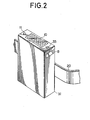
- FIG. 2 display 10 is mounted on the top of a casing 31 which is formed of an opaque material such as ABS resin or polycarbonate and which is strapped to the waist of the user using a belt 20 and held in a position that makes display 10 visible from above.
- Phototransistor 11 is located in a position adjacent one end of display 10 and flash lamp 33 in a position adjacent the other end of display 10. This is to keep the flash lamp from interferring with phototransistor 11.
- the light receiving surface of phototransistor 11 is covered by a glass member which is sealed to the edge of a hole in the casing to make it waterproof.
- the phototransistor Since the phototransistor is compact, it occupies a very small area on the top of casing 31. It would be advantageous to allow the user to increase the contrast of the message which is displayed under a relatively high lighting condition. This is simply done by covering the window of phototransistor 11 with a finger.
- phototransistor 11 is constantly powered once the pager is turned on. For power saving purposes, it is advantageous to shut off power supply to phototransistor 11 when there is no message being displayed.
- controller 4 comprises decoder 40, central processing unit 41 and input/output port 42.
- a DC-DC converter 21 provides boost to the DC potential applied from batteries 19 to decoder 40 to a level appropriate for operating the CPU 41.
- Lamp 18 is coupled to an output port and the collector of phototransistor 11 is coupled through resistor 12 to an output port and the collector of transistor 14 is connected to an input port.
- Fig. 4 is a block diagram of the method of operation of the display pager of Fig. 3.
- block 51 turns on the pager in response to the pressing on a power-on switch 22.
- Decision block 52 next tests for the presence of a message being displayed on display 10. If there is a message on display, execution block 53 applies a potential to phototransistor 11.
- decision block 54 which checks the potential at the collector.of transistor 14 to see if it is lower than a predetermined value. If display 10 is dimly lit under poor lighting condition, exit from decision block 54 is to block 55 that turns on lamp 18, illuminating display 10 and if it is brightly shone, exit from block 54 is to decision block 58.
- Block 58 tests the presence of the message on display 10 and detects when the message ceases to exist. If the message is still on display, exit from block 58 is to block 54 to loop around blocks 54 and 58 until the message disappears, whereupon block 59 is executed by removing the potential from phototransistor 11. With lamp 18 being turned on, control proceeds to decision block 56 which tests the potential at the base of transistor 14 to see if the ambinent condition is still dim or has changed to a level sufficient to illuminate display 10. If ambient condition has changed to the high luminance, exit from block 56 is to execution block 57 that turns off lamp 18 and thence to decision block 58 to keep the message on display under external light as control loops around blocks 54 and 58.
- decision block 60 Exit from decision block 56 is to decision block 60 if the poor lighting condition still prevails while message is being is displayed. Block 60 tests for the presence of the message still on display. If present, control exits to block 56 and loops around blocks 60 and 56 until the message disappears, whereupon exit from block 60 is to execution block 61 that turns off phototransistor 11 and lamp 18 simultaneously.
Abstract
Description
- The present invention relates to pagers and in particular to a pager with an automatically illuminated message display.
- Conventional display pagers include a manually operated mechanical switch to trigger a lamp to illuminate the display. However, it is desired to effect the illumination automatically according to ambient lighting condition.
- It is therefore an object of the present invention to provide a pager having a display which is illuminated automatically when external luminance is lower than a predetermined value.
- According to the invention, a pager includes a light sensor, such as phototransistor, which is sensitive to light externally illuminating the pager to generate a first signal when the sensed light is below the predetermined value. The first signal is supplied to a coincidence gate. A second signal to the coincidence gate is generated when there is a message on the display. Output from the coincidence gate is applied to a light source to illuminate the display to make it visible under poor lighting conditions.
- The elimination of mechanical switch has brought about advantages in that the light sensor requires.a smaller space than is required by mechanical switch, ensures an extended life time and waterproof - construction.
- The pager of the invention is further provided with a power saving feature that shuts off power supply to the light sensor in the absence of a message on display.
- The present invention will be described in further detail with reference to the accompanying drawings, in which:
- Fig. 1 is a block diagram of a pager according to an embodiment of the present invention;
- Fig. 2 is a perspective view of the pager;
- Fig. 3 is a block diagram of a pager according to another embodiment of the invention; and
- Fig. 4 is a flowchart describing the method of operation of the pager of the invention.
- Fig. 1 is a block diagram of a pager embodying the present invention. In Fig. 1, an antenna 1 receives a signal that is coupled to a
receiver 2 that supplies a demodulated output to awaveform shaper 3. The output ofwaveshaper 3 is coupled to acontroller 4. The function of the controller not only controls switching on and off ofreceiver 2 andwaveform shaper 3, it may also operate these circuits on an intermittent basis to extend the life of batteries in the pager. The controller includes a decoder and a central processing unit, the decoder being associated with an address PROM (programmable read-only memory) 5 and the CPU being associated with a message RAM (random access memory) 6. Decoder compares received address words with an address word stored inmemory 5 to see if the particular pager has been called. Ifcontroller 4 detects a call to this pager, analert oscillator 7 feeds aspeaker 8 to alert the user. A message word following the address word is placed into memory 6 for later retrieval upon operation of abutton 30. The message word is also fed to anLCD driver 9 and thence to a liquid-crystal display 10. - The pager of the present invention further includes a phototransistor 11 having a collector coupled through a current limiting
resistor 12 to abattery 19 and an emitter connected to the base of a transistor 14. Transistor 14 is biased into conduction in response to an emitter current being supplied from phototransistor 11 when it receives light rays from external source. Transistor 14 draws current throughresistor 13 when the lighting condition has a luminance which is sufficient to illuminate thedisplay 10. No current is thus generated in transistor 14 whendisplay 10 is poorly lit and under this condition the potential at the collector of transistor 14 is raised to a logical 1 which enables anAND gate 15. A second input to ANDgate 15 is supplied from the output ofLCD driver 9 which is at a logical 1 when message is being displayed. The' output of AND gate is at logical 1 when message is displayed while luminance is low and turns on atransistor 16, drawing a current throughlamp 18 and resistor 17.Lamp 18 illuminates display 10 to compensate for the insufficient luminance. - Flashing indication is also given when
flash oscillator 32 is activated in response to receipt of a call under the control ofcontroller 4 and flasheslamp 33. - It would be useful to the user to read the displayed message while carrying a pager on his waist. In Fig. 2,
display 10 is mounted on the top of acasing 31 which is formed of an opaque material such as ABS resin or polycarbonate and which is strapped to the waist of the user using abelt 20 and held in a position that makesdisplay 10 visible from above. Phototransistor 11 is located in a position adjacent one end ofdisplay 10 andflash lamp 33 in a position adjacent the other end ofdisplay 10. This is to keep the flash lamp from interferring with phototransistor 11. The light receiving surface of phototransistor 11 is covered by a glass member which is sealed to the edge of a hole in the casing to make it waterproof. Since the phototransistor is compact, it occupies a very small area on the top ofcasing 31. It would be advantageous to allow the user to increase the contrast of the message which is displayed under a relatively high lighting condition. This is simply done by covering the window of phototransistor 11 with a finger. - In the above embodiment phototransistor 11 is constantly powered once the pager is turned on. For power saving purposes, it is advantageous to shut off power supply to phototransistor 11 when there is no message being displayed. The circuit of Fig. 3 provides a power shut-off feature. In Fig. 3,
controller 4 comprisesdecoder 40,central processing unit 41 and input/output port 42. A DC-DC converter 21 provides boost to the DC potential applied frombatteries 19 todecoder 40 to a level appropriate for operating theCPU 41.Lamp 18 is coupled to an output port and the collector of phototransistor 11 is coupled throughresistor 12 to an output port and the collector of transistor 14 is connected to an input port. - Fig. 4 is a block diagram of the method of operation of the display pager of Fig. 3. In Fig. 4, block 51 turns on the pager in response to the pressing on a power-on
switch 22.Decision block 52 next tests for the presence of a message being displayed ondisplay 10. If there is a message on display,execution block 53 applies a potential to phototransistor 11. Next follows adecision block 54 which checks the potential at the collector.of transistor 14 to see if it is lower than a predetermined value. Ifdisplay 10 is dimly lit under poor lighting condition, exit fromdecision block 54 is to block 55 that turns onlamp 18,illuminating display 10 and if it is brightly shone, exit fromblock 54 is todecision block 58.Block 58 tests the presence of the message ondisplay 10 and detects when the message ceases to exist. If the message is still on display, exit fromblock 58 is to block 54 to loop aroundblocks block 59 is executed by removing the potential from phototransistor 11. Withlamp 18 being turned on, control proceeds todecision block 56 which tests the potential at the base of transistor 14 to see if the ambinent condition is still dim or has changed to a level sufficient to illuminatedisplay 10. If ambient condition has changed to the high luminance, exit fromblock 56 is toexecution block 57 that turns offlamp 18 and thence todecision block 58 to keep the message on display under external light as control loops aroundblocks - Exit from
decision block 56 is todecision block 60 if the poor lighting condition still prevails while message is being is displayed. Block 60 tests for the presence of the message still on display. If present, control exits to block 56 and loops aroundblocks block 60 is toexecution block 61 that turns off phototransistor 11 andlamp 18 simultaneously. - Thus, power supply to phototransistor 11 is shut off during periods when no message is displayed, thus minimizing power consumption.
- The foregoing description shows only preferred embodiments of the present invention. Various modifications are apparent to those skilled in the art without departing from the scope of the present invention which is only limited by the appended claims. Therefore, the embodiments shown and described are only illustrative, not restrictive.
Claims (7)
Applications Claiming Priority (2)
| Application Number | Priority Date | Filing Date | Title |
|---|---|---|---|
| JP178683/83 | 1983-09-26 | ||
| JP58178683A JPS6069922A (en) | 1983-09-26 | 1983-09-26 | Lighting device of display device for radio selective call receiver with display |
Publications (3)
| Publication Number | Publication Date |
|---|---|
| EP0135928A2 true EP0135928A2 (en) | 1985-04-03 |
| EP0135928A3 EP0135928A3 (en) | 1985-05-15 |
| EP0135928B1 EP0135928B1 (en) | 1987-12-23 |
Family
ID=16052723
Family Applications (1)
| Application Number | Title | Priority Date | Filing Date |
|---|---|---|---|
| EP84111419A Expired EP0135928B1 (en) | 1983-09-26 | 1984-09-25 | Pager with automatically illuminated display |
Country Status (8)
| Country | Link |
|---|---|
| US (1) | US4644350A (en) |
| EP (1) | EP0135928B1 (en) |
| JP (1) | JPS6069922A (en) |
| AU (1) | AU570382B2 (en) |
| CA (1) | CA1232026A (en) |
| DE (1) | DE3468285D1 (en) |
| HK (1) | HK2491A (en) |
| SG (1) | SG100190G (en) |
Cited By (2)
| Publication number | Priority date | Publication date | Assignee | Title |
|---|---|---|---|---|
| EP0168821A1 (en) * | 1984-07-18 | 1986-01-22 | Nec Corporation | Pager with display |
| EP0594459A1 (en) * | 1992-10-23 | 1994-04-27 | Nec Corporation | Radio paging receiver |
Families Citing this family (18)
| Publication number | Priority date | Publication date | Assignee | Title |
|---|---|---|---|---|
| US4754275A (en) * | 1985-06-07 | 1988-06-28 | Motorola, Inc. | Display with supplemental lighting system |
| JPS62198735U (en) * | 1986-06-06 | 1987-12-17 | ||
| US4755816A (en) * | 1986-10-29 | 1988-07-05 | Motorola Inc. | Battery saving method for a selective call radio paging receiver |
| JPH0528840Y2 (en) * | 1986-12-25 | 1993-07-23 | ||
| GB2199435B (en) * | 1986-12-25 | 1990-11-28 | Nec Corp | Pager receiver including a light emitting and a light sensing element adjacent to a translucent portion of a receiver housing |
| US4868563A (en) | 1987-09-25 | 1989-09-19 | Motorola, Inc. | Microcomputer controlled display backlight |
| IL90277A0 (en) * | 1989-05-12 | 1989-12-15 | Shmuel Shapira | System for locating compatible persons at a given locality |
| US5087906A (en) * | 1990-03-05 | 1992-02-11 | Motorola, Inc. | Selective call receiver having a light channel for providing a visual alert |
| US5239295A (en) * | 1990-04-16 | 1993-08-24 | Motorola, Inc. | Serial light interface which also functions as an ambient light detector |
| JPH0485418U (en) * | 1990-11-30 | 1992-07-24 | ||
| JP2564113Y2 (en) * | 1991-03-12 | 1998-03-04 | カシオ計算機株式会社 | LCD electronic devices |
| US5384577A (en) * | 1992-05-21 | 1995-01-24 | Motorola, Inc. | Combination display backlight and light sensor |
| US5398022A (en) * | 1993-01-22 | 1995-03-14 | Uniden America Corporation | Pager with display illumination |
| US5933088A (en) * | 1993-01-22 | 1999-08-03 | Uniden America Corporation | Pager with message sequencing |
| JP2518526B2 (en) * | 1993-06-28 | 1996-07-24 | 日本電気株式会社 | Wireless selective call receiver with display |
| JPH1013888A (en) * | 1996-06-19 | 1998-01-16 | Matsushita Electric Ind Co Ltd | Display device for selective call receiver |
| US6351656B1 (en) * | 1997-09-05 | 2002-02-26 | Motorola, Inc. | Method and apparatus for displaying a message which has been received |
| US7250846B2 (en) * | 2002-03-05 | 2007-07-31 | International Business Machines Corporation | Method and apparatus for providing dynamic user alert |
Citations (3)
| Publication number | Priority date | Publication date | Assignee | Title |
|---|---|---|---|---|
| DE2606691A1 (en) * | 1976-02-19 | 1977-09-01 | Bjoern Bluethgen | Personnel paging system in wristwatch - gives notice of telephone call by transmitting alphanumeric signal for display |
| GB2071376A (en) * | 1980-03-05 | 1981-09-16 | Campbell A M | Paging system |
| US4336524A (en) * | 1979-07-17 | 1982-06-22 | Levine Alfred B | Video display pager receiver with memory |
Family Cites Families (10)
| Publication number | Priority date | Publication date | Assignee | Title |
|---|---|---|---|---|
| US3437004A (en) * | 1967-07-25 | 1969-04-08 | Usm Corp | Sheet metal expandable fastener |
| US3849979A (en) * | 1973-07-24 | 1974-11-26 | Ise Electronics Corp | Electronic digital clocks |
| JPS5622569B2 (en) * | 1973-12-25 | 1981-05-26 | ||
| IT1098146B (en) * | 1978-08-24 | 1985-09-07 | Alfa Romeo Spa | ON BOARD PANEL FOR A VEHICLE |
| JPS5622569U (en) * | 1979-07-25 | 1981-02-28 | ||
| JPS5656046A (en) * | 1979-10-12 | 1981-05-16 | Matsushita Electric Ind Co Ltd | Radio receiver for vehicle mounting |
| JPS5792292U (en) * | 1980-11-27 | 1982-06-07 | ||
| JPS58138136A (en) * | 1982-02-12 | 1983-08-16 | Nec Corp | Inter-call receiver with display |
| DE3210800A1 (en) * | 1982-03-24 | 1983-10-06 | Zettler Elektrotechn Alois | Device for audible call forwarding |
| JPS60105329A (en) * | 1983-11-14 | 1985-06-10 | Sony Corp | Operation display device of audio equipment |
-
1983
- 1983-09-26 JP JP58178683A patent/JPS6069922A/en active Granted
-
1984
- 1984-09-25 US US06/654,082 patent/US4644350A/en not_active Expired - Lifetime
- 1984-09-25 EP EP84111419A patent/EP0135928B1/en not_active Expired
- 1984-09-25 AU AU33489/84A patent/AU570382B2/en not_active Expired
- 1984-09-25 CA CA000463961A patent/CA1232026A/en not_active Expired
- 1984-09-25 DE DE8484111419T patent/DE3468285D1/en not_active Expired
-
1990
- 1990-12-14 SG SG1001/90A patent/SG100190G/en unknown
-
1991
- 1991-01-03 HK HK24/91A patent/HK2491A/en not_active IP Right Cessation
Patent Citations (3)
| Publication number | Priority date | Publication date | Assignee | Title |
|---|---|---|---|---|
| DE2606691A1 (en) * | 1976-02-19 | 1977-09-01 | Bjoern Bluethgen | Personnel paging system in wristwatch - gives notice of telephone call by transmitting alphanumeric signal for display |
| US4336524A (en) * | 1979-07-17 | 1982-06-22 | Levine Alfred B | Video display pager receiver with memory |
| GB2071376A (en) * | 1980-03-05 | 1981-09-16 | Campbell A M | Paging system |
Cited By (4)
| Publication number | Priority date | Publication date | Assignee | Title |
|---|---|---|---|---|
| EP0168821A1 (en) * | 1984-07-18 | 1986-01-22 | Nec Corporation | Pager with display |
| EP0594459A1 (en) * | 1992-10-23 | 1994-04-27 | Nec Corporation | Radio paging receiver |
| AU665119B2 (en) * | 1992-10-23 | 1995-12-14 | Nec Corporation | Radio paging receiver |
| US5493280A (en) * | 1992-10-23 | 1996-02-20 | Nec Corporation | Radio paging receiver |
Also Published As
| Publication number | Publication date |
|---|---|
| US4644350A (en) | 1987-02-17 |
| AU570382B2 (en) | 1988-03-10 |
| SG100190G (en) | 1991-02-14 |
| HK2491A (en) | 1991-01-11 |
| AU3348984A (en) | 1985-04-04 |
| EP0135928B1 (en) | 1987-12-23 |
| JPH0447499B2 (en) | 1992-08-04 |
| DE3468285T (en) | 1988-02-04 |
| CA1232026A (en) | 1988-01-26 |
| JPS6069922A (en) | 1985-04-20 |
| DE3468285D1 (en) | 1988-02-04 |
| EP0135928A3 (en) | 1985-05-15 |
Similar Documents
| Publication | Publication Date | Title |
|---|---|---|
| EP0135928B1 (en) | Pager with automatically illuminated display | |
| US5933089A (en) | Pager with message display function | |
| US5833350A (en) | Switch cover plate providing automatic emergency lighting | |
| US6900735B2 (en) | Modular lighting device and actuation system | |
| US5548271A (en) | Data display radio pager | |
| US5337073A (en) | Portable radio equipment with a display back-lighting function | |
| CA1249635A (en) | Pager with display | |
| KR960009878B1 (en) | Alarm clock having an ambient light detector | |
| EP0641476A1 (en) | Combination display backlight and light sensor | |
| US4754275A (en) | Display with supplemental lighting system | |
| KR920001952B1 (en) | Battery selecting control method and apparatus thereof | |
| JPS643631A (en) | Liquid crystal display device | |
| JPH02135488A (en) | Display device for electric apparatus | |
| JPH06265848A (en) | Method and device for display | |
| US6262671B1 (en) | Pager having bar code reader | |
| KR0126943Y1 (en) | Illuminator stand functioning time subscription | |
| EP0783144A1 (en) | Clock | |
| KR940002334Y1 (en) | Control circuit of power supply | |
| JPH0332104Y2 (en) | ||
| KR950010684B1 (en) | Lamp control unit of fan | |
| KR0137008B1 (en) | Lamp Lighting Device and Method of LCD Remote Control | |
| JPH08152491A (en) | Illumination device of timepiece | |
| JPS6323841Y2 (en) | ||
| JPH09172481A (en) | Portable electronic equipment | |
| KR20000031602A (en) | Illumination automatically adjusting apparatus for car audio system |
Legal Events
| Date | Code | Title | Description |
|---|---|---|---|
| PUAI | Public reference made under article 153(3) epc to a published international application that has entered the european phase |
Free format text: ORIGINAL CODE: 0009012 |
|
| PUAL | Search report despatched |
Free format text: ORIGINAL CODE: 0009013 |
|
| 17P | Request for examination filed |
Effective date: 19840925 |
|
| AK | Designated contracting states |
Designated state(s): DE FR GB |
|
| AK | Designated contracting states |
Designated state(s): DE FR GB |
|
| 17Q | First examination report despatched |
Effective date: 19860423 |
|
| GRAA | (expected) grant |
Free format text: ORIGINAL CODE: 0009210 |
|
| AK | Designated contracting states |
Kind code of ref document: B1 Designated state(s): DE FR GB |
|
| REF | Corresponds to: |
Ref document number: 3468285 Country of ref document: DE Date of ref document: 19880204 |
|
| ET | Fr: translation filed | ||
| PLBE | No opposition filed within time limit |
Free format text: ORIGINAL CODE: 0009261 |
|
| STAA | Information on the status of an ep patent application or granted ep patent |
Free format text: STATUS: NO OPPOSITION FILED WITHIN TIME LIMIT |
|
| 26N | No opposition filed | ||
| REG | Reference to a national code |
Ref country code: GB Ref legal event code: IF02 |
|
| PGFP | Annual fee paid to national office [announced via postgrant information from national office to epo] |
Ref country code: FR Payment date: 20030909 Year of fee payment: 20 |
|
| PGFP | Annual fee paid to national office [announced via postgrant information from national office to epo] |
Ref country code: GB Payment date: 20030924 Year of fee payment: 20 |
|
| PGFP | Annual fee paid to national office [announced via postgrant information from national office to epo] |
Ref country code: DE Payment date: 20031002 Year of fee payment: 20 |
|
| PG25 | Lapsed in a contracting state [announced via postgrant information from national office to epo] |
Ref country code: GB Free format text: LAPSE BECAUSE OF EXPIRATION OF PROTECTION Effective date: 20040924 |
|
| REG | Reference to a national code |
Ref country code: GB Ref legal event code: PE20 |