EP0136520A2 - Apparatus for recording densitometric values of a control strip - Google Patents
Apparatus for recording densitometric values of a control strip Download PDFInfo
- Publication number
- EP0136520A2 EP0136520A2 EP84110087A EP84110087A EP0136520A2 EP 0136520 A2 EP0136520 A2 EP 0136520A2 EP 84110087 A EP84110087 A EP 84110087A EP 84110087 A EP84110087 A EP 84110087A EP 0136520 A2 EP0136520 A2 EP 0136520A2
- Authority
- EP
- European Patent Office
- Prior art keywords
- control strip
- densitometer
- absolute position
- evaluation
- support table
- Prior art date
- Legal status (The legal status is an assumption and is not a legal conclusion. Google has not performed a legal analysis and makes no representation as to the accuracy of the status listed.)
- Granted
Links
- 238000011156 evaluation Methods 0.000 claims abstract description 14
- 230000003287 optical effect Effects 0.000 claims description 4
- 238000005259 measurement Methods 0.000 description 15
- 239000000463 material Substances 0.000 description 2
- 230000004913 activation Effects 0.000 description 1
- 239000003086 colorant Substances 0.000 description 1
- 238000011109 contamination Methods 0.000 description 1
- 238000000034 method Methods 0.000 description 1
- 238000012544 monitoring process Methods 0.000 description 1
- 230000000717 retained effect Effects 0.000 description 1
Images
Classifications
-
- G—PHYSICS
- G01—MEASURING; TESTING
- G01N—INVESTIGATING OR ANALYSING MATERIALS BY DETERMINING THEIR CHEMICAL OR PHYSICAL PROPERTIES
- G01N21/00—Investigating or analysing materials by the use of optical means, i.e. using sub-millimetre waves, infrared, visible or ultraviolet light
- G01N21/17—Systems in which incident light is modified in accordance with the properties of the material investigated
- G01N21/59—Transmissivity
- G01N21/5907—Densitometers
-
- B—PERFORMING OPERATIONS; TRANSPORTING
- B41—PRINTING; LINING MACHINES; TYPEWRITERS; STAMPS
- B41F—PRINTING MACHINES OR PRESSES
- B41F33/00—Indicating, counting, warning, control or safety devices
- B41F33/0036—Devices for scanning or checking the printed matter for quality control
Definitions
- the invention relates to a device of the type mentioned in the preamble of claim 1.
- the control strip reproduces the colors used to produce a colored image, for example a printed sheet.
- the color density of the individual color fields of the control strip can be measured using a densitometer. For the evaluation of each measurement, it is necessary that the associated color field, ie. H. the measurement location on the control strip is known.
- a device of the generic type is already known in which the densitometer is automatically moved along the control strip for each measurement.
- the entire control strip is measured field by field.
- the densitometer is designed in such a way that it can recognize the color field boundaries and thus count the color fields passed over. It is a relatively complex system which is generally only installed in automatic densitometer systems, such as those used in large printers for monitoring several printing machines.
- a further disadvantage of the known device is considered that, because of the use of the counting principle for determining the measuring location, the densitometer is used for each measurement from an initial position the control strip must be moved to the desired measuring location.
- the measuring location thus results as a relative position, which is related to a very specific starting position, which must be sought first for each measuring process.
- the known device can therefore in particular not be used in conjunction with a hand-held densitometer, the advantage of which is that it can be placed at any time on any color field whose color values are to be measured densitometrically.
- An arrangement of absolute position sensors with a course corresponding to the course of the control strip is assigned to the support table. This arrangement is such that when the control strip carrier is placed on the support table and aligned on it, the respective color fields of the control strip correspond to certain absolute position sensors. If the densitometer is moved over a certain color field, the corresponding absolute position sensor emits a signal which can be used to determine the measurement location in the evaluation device.
- Such absolute position encoders are technically very simple and inexpensive to represent.
- the device according to the invention makes it possible to determine each measuring location absolutely, so that a time-consuming movement of the control strip from a certain starting point to the desired measuring location is no longer necessary for each measurement.
- the device according to the invention can in particular also be used in connection with simple and inexpensive handheld densitometers, the advantage of which is that they can be placed directly on a desired measuring location.
- a magnet is arranged on the densitometer near its reading head and the absolute position sensors are electromagnetic sensors which are electrically connected to the evaluation device. Both the electromagnetic sensors and the magnet are very simple and cheap commercially available components, which are also very insensitive and therefore easy to maintain.
- the absolute position sensors are preferably arranged below the support table and in a row parallel to the control strip.
- the arrangement below the support table means that they are not exposed to the contamination that is generally unavoidable in a printing company. It only has to be ensured that an activation of the absolute position encoder is possible through the support table.
- the marks for aligning the control strip carrier can be designed as optical markings or as stops.
- the device according to the invention can in principle comprise densitometers of any type.
- the densitometer is a manual densitometer which is connected to a stationary evaluation device.
- the advantage of the simple, easy-to-use manual densitometer is thus fully retained, while at the same time the performance of an automatic densitometer system which is generally much more expensive is achieved.
- the operator of the printing press can carry out his measurement directly at this at any time that is deemed expedient and at precisely the location of the control strip, which the operator selected on the basis of his experience with the machine to be tested and with the material used for the printing sheet.
- the evaluation device preferably comprises a desktop computer, a printer and a monitor.
- the desktop computer (preferably a basic computer) has a memory so that it can provide the time, the date, technical data of the printing press, number of the measurement series and other information essential for the log output by the printer. In addition, it should make previously acquired data or comparison data visible on the screen, which should facilitate the interpretation of the newly measured data.
- the view appears on the screen bar made data of the control strip with reference to a horizontal line 0 and two of these adjacent strips, which limit the variable tolerance field to be observed, so that the operator can immediately identify any "points" that fall outside the tolerance band; A reference information on the measuring locations which correspond to the recording points in the printing machine also appears on the screen.
- the person operating the handheld densitometer will preferably monitor the areas of the control strip which, based on their experience and knowledge of the printing press and the material, they know that there is a certain probability that they will fall outside the specified, stored tolerance band. After making changes or adjustments, the operator can compare the measured values with previously stored values in order to get to the desired quality level in the shortest possible time (which is available in the form of stored target data) and to keep this level for the duration of several measurement runs through constant To be able to receive control interventions on the printing press.
- the memory of the computer is supplied with data from the printing machine gives the possibility of producing a protocol by means of the printer as soon as a measured value acquisition is carried out, whereby an irrefutable document is provided which is used to determine the quality of a particular lot of printed sheets and can serve as proof of the work performed.
- the device according to the invention is shown and described in connection with a manual densitometer.
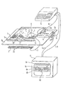
- the figure shows a schematic representation of a device with a support table, a manual densitometer, an arrangement of absolute position sensors assigned to the support table, and an evaluation unit connected to the manual densitometer and the absolute position sensors.
- the printed sheet is placed on a support table 1b; its control strip 1 is positioned exactly by means of the optical markings 1a.
- an arrangement 2 of electromagnetic sensors 2a is provided below the support table 1b; these are activated by the magnet 3a arranged on the hand-held densitometer 3 near the reading head in each measurement carried out by means of the hand-held densitometer 3 and give electronic impulses to the devices 4, 5, 6 connected to the hand-held densitometer, thereby giving a written indication of the measuring position on the printer 4 output protocol 4a, a display of the position on the screen 6 and a comparison with target measured values or previously recorded and stored in the computer 5.
- the hand densitometer 3 can be of a known type; it is provided with a connecting cable 8 and a magnet 3a. When it is in a position for optical measurement recording, the magnet 3a activates the magnetic sensors 2a connected to the printer 4 via cable 9.
- the printer is coupled to an interface (RS 232 C) and connected to the computer 5 and the screen 6 by means of the cables 10, 11.
- the electronic devices te 2, 3, 4, 5, 6 are connected to an electrical power source 7 via cables 7a, 7b, 7c and 8, 9, respectively.
- the invention does not rule out that the manual densitometer 3 of the reflection densitometer type is replaced by a densitometer of another type, the measured values output in the form of pulses being processed by the devices 4, 5, 6 connected to it.
- the interface (RS 232 C) can also be combined with the computer 5 to form one device.
- these appear on the screen 6 with reference to a line 0 as stripes in an upper positive field and a lower negative field, the corresponding permissible tolerance ranges being indicated by the bands 6b, 6c are displayed so that the "dots" 6d which fall outside these bands 6b, 6c are immediately recognized; otherwise, the measurement location 6e appears for each measured value.
- the individual components 4, 5, 6 can also be structurally connected so that they form a single block, possibly combined with the support plate 1b, arranged in the space below it; in addition, the device according to the invention allows different connections between the electronic devices 4, 2, 5, 6 and the manual densitometer 3.
Abstract
Description
Die Erfindung betrifft eine Einrichtung der im Oberbegriff des Anspruches 1 genannten Art.The invention relates to a device of the type mentioned in the preamble of claim 1.
Der Kontrollstreifen gibt die zur Herstellung eines farbigen Bildes, beispielsweise eines Druckbogens, verwendeten Farben wieder. Die Farbdichte der einzelnen Farbfelder des Kontrollstreifens kann mit Hilfe eines Densitometers gemessen werden. Für die Auswertung jeder Messung ist es erforderlich, daß zu jedem ermittelten Wert auch das zugehörige Farbfeld, d. h. also der Meßort auf dem Kontrollstreifen, bekannt ist.The control strip reproduces the colors used to produce a colored image, for example a printed sheet. The color density of the individual color fields of the control strip can be measured using a densitometer. For the evaluation of each measurement, it is necessary that the associated color field, ie. H. the measurement location on the control strip is known.
Es ist schon eine Einrichtung der gattungsgemäßen Art bekannt, bei welcher das Densitometer für jede Messung automatisch entlang dem Kontrollstreifen verfahren wird. Dabei wird der gesamte Kontrollstreifen Feld für Feld ausgemessen. Um den Meßort bestimmen zu können, ist das Densitometer so ausgebildet, daß es die Farbfeldgrenzen erkennen und so die überfahrenen Farbfelder zählen kann. Es handelt sich dabei um ein verhältnismäßig aufwendiges System, welches im allgemeinen nur bei automatischen Densitometer-Anlagen eingebaut wird, wie sie beispielsweise in großen Druckereien zur Überwachung mehrerer Druckmaschinen verwendet werden. Als weiterer Nachteil der bekannten Einrichtung wird angesehen, daß wegen der Verwendung des Zählprinzips zur Meßortbestimmung das Densitometer bei jeder Messung von einer Anfangsstellung aus über den Kontrollstreifen bis zu dem gewünschten Meßort verfahren werden muß. Der Meßort ergibt sich demnach als Relativposition, welche auf eine ganz bestimmte Anfangsposition bezogen ist, die bei jedem Meßvorgang zuerst aufgesucht werden muß. Die bekannte Einrichtung kann deshalb insbesondere nicht in Verbindung mit einem Handdensitometer verwendet werden, dessen Vorteil es gerade ist, daß es jederzeit unmittelbar auf ein beliebiges Farbfeld aufgesetzt werden kann, dessen Farbwerte densitometrisch gemessen werden sollen.A device of the generic type is already known in which the densitometer is automatically moved along the control strip for each measurement. The entire control strip is measured field by field. In order to be able to determine the measuring location, the densitometer is designed in such a way that it can recognize the color field boundaries and thus count the color fields passed over. It is a relatively complex system which is generally only installed in automatic densitometer systems, such as those used in large printers for monitoring several printing machines. A further disadvantage of the known device is considered that, because of the use of the counting principle for determining the measuring location, the densitometer is used for each measurement from an initial position the control strip must be moved to the desired measuring location. The measuring location thus results as a relative position, which is related to a very specific starting position, which must be sought first for each measuring process. The known device can therefore in particular not be used in conjunction with a hand-held densitometer, the advantage of which is that it can be placed at any time on any color field whose color values are to be measured densitometrically.
Es ist die Aufgabe der vorliegenden Erfindung, eine Einrichtung der gattungsgemäßen Art zu schaffen, welche ohne die Verwendung aufwendiger Zähleinrichtungen auskommt und welche auch die Vermessung und Meßortbestimmung einzelner Farbfelder des Kontrollstreifens erlaubt, ohne daß das Densitometer bei jeder Messung von einem bestimmten Ausgangspunkt aus über den gesamten Kontrollstreifen geführt wird.It is the object of the present invention to provide a device of the generic type which does not require the use of complex counting devices and which also allows the measurement and determination of the measurement location of individual color fields of the control strip without the densitometer having to measure each measurement from a specific starting point entire control strip.
Diese Aufgabe ist erfindungsgemäß durch die im Kennzeichen des Anspruches 1 enthaltenen Merkmale gelöst.This object is achieved by the features contained in the characterizing part of claim 1.
Dem Auflagetisch ist eine Anordnung von Absolutpositionsgebern mit einem dem Verlauf des Kontrollstreifens entsprechenden Verlauf zugeordnet. Diese Anordnung ist so getroffen, daß bei auf den Auflagetisch aufgelegtem und auf diesem ausgerichtetem Kontrollstreifenträger den einzelnen Farbfeldern des Kontrollstreifens jeweils bestimmte Absolutpositionsgeber entsprechen. Wenn das Densitometer über ein bestimmtes Farbfeld geführt wird, gibt der entsprechende Absolutpositionsgeber ein Signal ab, welches zur Bestimmung des Meßortes in der Auswerteeinrichtung verwendet werden kann. Derartige Absolutpositionsgeber lassen sich technisch sehr einfach und preiswert darstellen. Die erfindungsgemäße Einrichtung erlaubt es, jeden Meßort absolut zu bestimmen, so daß ein zeitaufwendiges Abfahren des Kontrollstreifens von einem bestimmten Anfangspunkt bis zu dem gewünschten Meßort bei jeder Messung nicht mehr erforderlich ist. Die erfindungsgemäße Einrichtung kann insbesondere auch in Verbindung mit einfachen und billigen Handdensitometern verwendet werden, deren Vorteil gerade darin liegt, daß sie unmittelbar auf einen gewünschten Meßort aufgesetzt werden können.An arrangement of absolute position sensors with a course corresponding to the course of the control strip is assigned to the support table. This arrangement is such that when the control strip carrier is placed on the support table and aligned on it, the respective color fields of the control strip correspond to certain absolute position sensors. If the densitometer is moved over a certain color field, the corresponding absolute position sensor emits a signal which can be used to determine the measurement location in the evaluation device. Such absolute position encoders are technically very simple and inexpensive to represent. The device according to the invention makes it possible to determine each measuring location absolutely, so that a time-consuming movement of the control strip from a certain starting point to the desired measuring location is no longer necessary for each measurement. The device according to the invention can in particular also be used in connection with simple and inexpensive handheld densitometers, the advantage of which is that they can be placed directly on a desired measuring location.
In einer Ausgestaltung der Erfindung ist vorgesehen, daß am Densitometer nahe seinem Lesekopf ein Magnet angeordnet ist und die Absolutpositionsgeber mit der Auswerteeinrichtung elektrisch verbundene, elektromagnetische Sensoren sind. Sowohl die elektromagnetischen Sensoren als auch der Magnet stellen sehr einfache und billige handelsübliche Bauteile dar, welche zudem sehr unempfindlich und damit wartungsfreundlich sind.In one embodiment of the invention it is provided that a magnet is arranged on the densitometer near its reading head and the absolute position sensors are electromagnetic sensors which are electrically connected to the evaluation device. Both the electromagnetic sensors and the magnet are very simple and cheap commercially available components, which are also very insensitive and therefore easy to maintain.
Die Absolutspositionsgeber sind vorzugsweise unterhalb des Auflagetisches und in einer Reihe parallel zu dem Kontrollstreifen angeordnet. Durch die Anordnung unterhalb des Auflagetisches sind sie den in einem Druckereibetrieb im allgemeinen unvermeidlichen Verschmutzungen nicht ausgesetzt. Es muß dabei lediglich gewährleistet sein, daß eine Aktivierung der Absolutpositionsgeber durch den Auflagetisch hindurch möglich ist.The absolute position sensors are preferably arranged below the support table and in a row parallel to the control strip. The arrangement below the support table means that they are not exposed to the contamination that is generally unavoidable in a printing company. It only has to be ensured that an activation of the absolute position encoder is possible through the support table.
Die Marken zum Ausrichten des Kontrollstreifenträgers können erfindungsgemäß als optische Markierungen oder auch als Anschläge ausgebildet sein.According to the invention, the marks for aligning the control strip carrier can be designed as optical markings or as stops.
Die erfindungsgemäße Einrichtung kann grundsätzlich Densitometer beliebiger Bauart umfassen. In einer bevorzugten Ausgestaltung der Erfindung ist jedoch vorgesehen, daß das Densitometer ein Handdensitometer ist, welches an eine stationäre Auswerteeinrichtung angeschlossen ist. Damit bleibt der Vorteil des einfachen, leicht zu handhabenden Handdensitometers voll erhalten, während gleichzeitig die Leistungen einer im allgemeinen sehr viel teuereren automatischen Densitometeranlage erreicht werden. Der Bedienungsmann der Druckmaschine kann direkt an dieser in jedem für zweckmäßig gehaltenen Augenblick und an exakt dem Ort des Kontrollstreifens, welcher vom Bedienungsmann auf Grund seiner Erfahrung mit der zu prüfenden Maschine und mit dem für den Druckbogen verwendeten Material ausgewählt wurde, seine Messung durchführen.The device according to the invention can in principle comprise densitometers of any type. In a preferred embodiment of the invention, however, it is provided that the densitometer is a manual densitometer which is connected to a stationary evaluation device. The advantage of the simple, easy-to-use manual densitometer is thus fully retained, while at the same time the performance of an automatic densitometer system which is generally much more expensive is achieved. The operator of the printing press can carry out his measurement directly at this at any time that is deemed expedient and at precisely the location of the control strip, which the operator selected on the basis of his experience with the machine to be tested and with the material used for the printing sheet.
Die Auswerteeinrichtung umfaßt vorzugsweise einen Tischrechner, einen Drucker und einen Bildschirm. Der Tischrechner (vorzugsweise ein Basicrechner) weist einen Speicher auf, so daß er die Zeit, das Datum, technische Daten der Druckmaschine, Nummer der Meßreihe sowie andere für das vom Drucker ausgebene Protokoll wesentliche Angaben zur Verfügung stellen kann. Außerdem soll er früher erfaßte Daten oder Vergleichsdaten auf dem Bildschirm sichtbar machen, welche die Interpretation der neu gemessenen Daten erleichtern sollen. Auf dem Bildschirm erscheinen außer den "Protokoll-Daten" die sichtbar gemachten Daten des Kontrollstreifens mit Bezug auf eine horizontale Linie 0 und zwei dieser benachbarte Streifen, welche das zu beachtende, variable Toleranzfeld begrenzen, so daß die Bedienungsperson sofort eventuelle "Punkte" feststellen kann, die aus dem Toleranzband herausfallen; auf dem Bildschirm erscheint außerdem eine Referenzangabe zu den Meßorten, welche den Aufzeichnungspunkten in der Druckmaschine entsprechen.The evaluation device preferably comprises a desktop computer, a printer and a monitor. The desktop computer (preferably a basic computer) has a memory so that it can provide the time, the date, technical data of the printing press, number of the measurement series and other information essential for the log output by the printer. In addition, it should make previously acquired data or comparison data visible on the screen, which should facilitate the interpretation of the newly measured data. In addition to the "Protocol data", the view appears on the screen bar made data of the control strip with reference to a
Die Person, welche das Handdensitometer bedient, wird vorzugsweise die Bereiche des Kontrollstreifens überwachen, von denen sie nach ihrer Erfahrung und Kenntnis der Druckmaschine sowie des Materials weiß, daß eine gewisse Wahrscheinlichkeit dafür besteht, daß sie aus dem vorgegebenen, gespeicherten Toleranzband herausfallen. Die Bedienungsperson kann nach Ausführung von Änderungen oder Regulierungen die Meßwerte mit früher gespeicherten Werten vergleichen, um in möglichst kurzer Zeit auf das erwünschte Qualitätsniveau zu kommen (welches in Form von gespeicherten Soll-Daten vorliegt) und um dieses Niveau für die Zeit mehrerer Meßdurchgänge durch ständige Reguliereingriffe an der Druckmaschine erhalten zu können.The person operating the handheld densitometer will preferably monitor the areas of the control strip which, based on their experience and knowledge of the printing press and the material, they know that there is a certain probability that they will fall outside the specified, stored tolerance band. After making changes or adjustments, the operator can compare the measured values with previously stored values in order to get to the desired quality level in the shortest possible time (which is available in the form of stored target data) and to keep this level for the duration of several measurement runs through constant To be able to receive control interventions on the printing press.
Dadurch, daß der Speicher des Rechners mit Daten der Druckmaschine beliefert wird, ist die Möglichkeit der Herstellung eines Protokolls mittels des Druckers gegeben, sobald eine Meßwerterfassung durchgeführt wird, wodurch ein unwiderlegbares Dokument bereitgestellt wird, welches zur Bestimmung der Qualität eines bestimmten Loses von Druckbogen und zum Nachweis der durchgeführten Arbeit dienen kann.The fact that the memory of the computer is supplied with data from the printing machine gives the possibility of producing a protocol by means of the printer as soon as a measured value acquisition is carried out, whereby an irrefutable document is provided which is used to determine the quality of a particular lot of printed sheets and can serve as proof of the work performed.
In einem Ausführungsbeispiel ist die erfindungsgemäße Einrichtung in Verbindung mit einem Handdensitometer dargestellt und beschrieben. Die Figur zeigt eine schematische Darstellung einer Einrichtung mit einem Auflagetisch, einem Handdensitometer, einer dem Auflagetisch zugeordneten Anordnung von Absolutpositionsgebern sowie einer an das Handdensitometer und die Absolutpositionsgeber angeschlossenen Auswerteeinheit.In one embodiment, the device according to the invention is shown and described in connection with a manual densitometer. The figure shows a schematic representation of a device with a support table, a manual densitometer, an arrangement of absolute position sensors assigned to the support table, and an evaluation unit connected to the manual densitometer and the absolute position sensors.
Der Druckbogen wird auf einen Auflagetisch 1b aufgelegt; sein Kontrollstreifen 1 wird mittels der optischen Markierungen 1a exakt positioniert. In Übereinstimmung mit der Position des Kontrollstreifens 1 ist unterhalb des Auflagetisches 1b eine Anordnung 2 von elektromagnetischen Sensoren 2a vorgesehen; diese werden durch den am Handdensitometer 3 nahe dem Lesekopf angeordneten Magneten 3a bei jeder mittels des Handdensitometers 3 ausgeführten Messung aktiviert und geben elektronische Impulse an die mit dem Handdensitometer verbundenen Geräte 4, 5, 6, wodurch man eine geschriebene Anzeige der Meßposition auf dem vom Drucker 4 ausgegebenen Protokoll 4a, eine Anzeige der Position auf dem Bildschirm 6 und einen Vergleich mit Sollmeßwerten oder früher aufgenommenen und im Rechner 5 gespeicherten Meßwerten erhält. Das Handdensitometer 3 kann von bekannter Art sein; es ist mit einem Verbindungskabel 8 und einem Magneten 3a versehen. Wenn es sich in einer Position für eine optische Meßwertaufnahme befindet,aktiviert der Magnet 3a die mit dem Drucker 4 über Kabel 9 verbundenen Magnetsensoren 2a. Der Drucker ist mit einer Schnittstelle (RS 232 C) gekoppelt und mittels der Kabel 10, 11 mit dem Rechner 5 und dem Bildschirm 6 verbunden. Die elektronischen Geräte 2, 3, 4, 5, 6 sind über die Kabel 7a, 7b, 7c bzw. 8, 9 mit einer elektrischen Stromquelle 7 verbunden. Die Erfindung schließt nicht aus, daß das Handdensitometer 3 vom Typ des Reflexions-Densitometers durch ein Densitometer anderer Art ersetzt wird, dessen in Form von Impulsen ausgegebene Meßwerte von den mit diesem verbundenen Geräten 4, 5, 6 verarbeitet werden. Anstatt die Schnittstelle (RS 232 C) mit dem Drucker 4 zu verbinden, kann der letztere auch mit dem Rechner 5 zu einem Gerät zusammengefaßt sein.The printed sheet is placed on a support table 1b; its control strip 1 is positioned exactly by means of the
Um eine praktisch sofortige Interpretaiton der aufgenommenen Meßwerte zu ermöglichen, erscheinen diese gemäß der Erfindung auf dem Bildschirm 6 mit Bezug auf eine Linie 0 als Streifen in einem oberen positiven Feld und einem unteren negativen Feld, wobei die entsprechenden zulässigen Toleranzbereiche durch die Bänder 6b, 6c angezeigt werden, so daß die "Punkte" 6d, welche außerhalb dieser Bänder 6b, 6c fallen, sofort erkannt werden; im übrigen erscheint für jeden Meßwert der Meßort 6e.In order to enable a practically immediate interpretation of the recorded measured values, according to the invention, these appear on the screen 6 with reference to a
Die einzelnen Komponenten 4, 5, 6 können erfindungsgemäß auch konstruktiv so verbunden sein, daß sie einen einzigen, eventuell mit der Auflageplatte 1b zusammengefaßten, in dem Raum unterhalb derselben angeordneten Block bilden; außerdem erlaubt die erfindungsgemäße Einrichtung unterschiedliche Verbindungen zwischen den elektronischen Geräten 4, 2, 5, 6 und dem Handdensitometer 3.According to the invention, the
Claims (6)
Applications Claiming Priority (2)
| Application Number | Priority Date | Filing Date | Title |
|---|---|---|---|
| IT04835/83A IT1172552B (en) | 1983-08-25 | 1983-08-25 | DENSITOMETRIC SURVEYING SYSTEM ON PRINT CONTROL STRIPS |
| IT483583 | 1983-08-25 |
Publications (3)
| Publication Number | Publication Date |
|---|---|
| EP0136520A2 true EP0136520A2 (en) | 1985-04-10 |
| EP0136520A3 EP0136520A3 (en) | 1986-02-05 |
| EP0136520B1 EP0136520B1 (en) | 1989-10-25 |
Family
ID=11114670
Family Applications (1)
| Application Number | Title | Priority Date | Filing Date |
|---|---|---|---|
| EP84110087A Expired EP0136520B1 (en) | 1983-08-25 | 1984-08-23 | Apparatus for recording densitometric values of a control strip |
Country Status (3)
| Country | Link |
|---|---|
| EP (1) | EP0136520B1 (en) |
| DE (1) | DE3480300D1 (en) |
| IT (1) | IT1172552B (en) |
Cited By (4)
| Publication number | Priority date | Publication date | Assignee | Title |
|---|---|---|---|---|
| EP0353624A2 (en) * | 1988-08-03 | 1990-02-07 | M.A.N.-ROLAND Druckmaschinen Aktiengesellschaft | Device for evaluating copies |
| EP0356705A2 (en) * | 1988-08-30 | 1990-03-07 | M.A.N.-ROLAND Druckmaschinen Aktiengesellschaft | Data reading unit for an ink control devices |
| EP0410253A2 (en) * | 1989-07-28 | 1991-01-30 | MAN Roland Druckmaschinen AG | Device for carrying out a comprehensive quality control on printed sheets |
| AT413681B (en) * | 2003-02-05 | 2006-05-15 | Roland Man Druckmasch | COLOR REMOTE CONTROL |
Citations (6)
| Publication number | Priority date | Publication date | Assignee | Title |
|---|---|---|---|---|
| FR1200742A (en) * | 1956-09-05 | 1959-12-23 | Crosfield J F Ltd | Improvements to printing processes |
| US3141727A (en) * | 1962-12-14 | 1964-07-21 | Jr Harry L Devereaux | Film-strip density curve plotting device |
| US3367230A (en) * | 1963-12-04 | 1968-02-06 | Welch Scient Company | Light density scanning device |
| FR1529112A (en) * | 1967-06-22 | 1968-06-14 | Gl Upravlenie Energetiki I Ele | Relative object movement parameter sensor |
| US3995958A (en) * | 1975-07-21 | 1976-12-07 | Hallmark Cards, Incorporated | Automatic densitometer and method of color control in multi-color printing |
| US4110610A (en) * | 1975-12-17 | 1978-08-29 | Candid Logic, Inc. | Digital electrical position transducer |
Family Cites Families (1)
| Publication number | Priority date | Publication date | Assignee | Title |
|---|---|---|---|---|
| BE849338A (en) * | 1976-12-13 | 1977-04-01 | DEVICE TO DISPLAY THE MOVEMENTS OF THE CLUTCH PEDAL |
-
1983
- 1983-08-25 IT IT04835/83A patent/IT1172552B/en active
-
1984
- 1984-08-23 DE DE8484110087T patent/DE3480300D1/en not_active Expired
- 1984-08-23 EP EP84110087A patent/EP0136520B1/en not_active Expired
Patent Citations (6)
| Publication number | Priority date | Publication date | Assignee | Title |
|---|---|---|---|---|
| FR1200742A (en) * | 1956-09-05 | 1959-12-23 | Crosfield J F Ltd | Improvements to printing processes |
| US3141727A (en) * | 1962-12-14 | 1964-07-21 | Jr Harry L Devereaux | Film-strip density curve plotting device |
| US3367230A (en) * | 1963-12-04 | 1968-02-06 | Welch Scient Company | Light density scanning device |
| FR1529112A (en) * | 1967-06-22 | 1968-06-14 | Gl Upravlenie Energetiki I Ele | Relative object movement parameter sensor |
| US3995958A (en) * | 1975-07-21 | 1976-12-07 | Hallmark Cards, Incorporated | Automatic densitometer and method of color control in multi-color printing |
| US4110610A (en) * | 1975-12-17 | 1978-08-29 | Candid Logic, Inc. | Digital electrical position transducer |
Cited By (7)
| Publication number | Priority date | Publication date | Assignee | Title |
|---|---|---|---|---|
| EP0353624A2 (en) * | 1988-08-03 | 1990-02-07 | M.A.N.-ROLAND Druckmaschinen Aktiengesellschaft | Device for evaluating copies |
| EP0353624A3 (en) * | 1988-08-03 | 1990-09-05 | M.A.N.-Roland Druckmaschinen Aktiengesellschaft | Device for evaluating copies |
| EP0356705A2 (en) * | 1988-08-30 | 1990-03-07 | M.A.N.-ROLAND Druckmaschinen Aktiengesellschaft | Data reading unit for an ink control devices |
| EP0356705A3 (en) * | 1988-08-30 | 1991-05-08 | M.A.N.-ROLAND Druckmaschinen Aktiengesellschaft | Data reading unit for an ink control devices |
| EP0410253A2 (en) * | 1989-07-28 | 1991-01-30 | MAN Roland Druckmaschinen AG | Device for carrying out a comprehensive quality control on printed sheets |
| EP0410253A3 (en) * | 1989-07-28 | 1991-07-31 | Man Roland Druckmaschinen Ag | Device for carrying out a comprehensive quality control on printed sheets |
| AT413681B (en) * | 2003-02-05 | 2006-05-15 | Roland Man Druckmasch | COLOR REMOTE CONTROL |
Also Published As
| Publication number | Publication date |
|---|---|
| DE3480300D1 (en) | 1989-11-30 |
| EP0136520A3 (en) | 1986-02-05 |
| IT8304835A0 (en) | 1983-08-25 |
| EP0136520B1 (en) | 1989-10-25 |
| IT1172552B (en) | 1987-06-18 |
Similar Documents
| Publication | Publication Date | Title |
|---|---|---|
| EP0064024B1 (en) | Method and device for the colorimetric analysis of a printed colour test scale | |
| DE2253189C3 (en) | Method and device for the automatic control of the color density of printing inks applied to a moving web | |
| EP0410253A2 (en) | Device for carrying out a comprehensive quality control on printed sheets | |
| DE3830731A1 (en) | DEVICE FOR COLOR MEASUREMENT | |
| DE2922965A1 (en) | DEVICE USED FOR PRINTING UNITS TO DETERMINE RELATIVE SCREEN AREAS | |
| EP0356705B1 (en) | Data reading unit for an ink control devices | |
| AT394781B (en) | INCREMENTAL MEASURING SYSTEM | |
| DE2735943C2 (en) | Device for checking the print quality of multi-colored printed sheets stored in a stack | |
| EP0136520B1 (en) | Apparatus for recording densitometric values of a control strip | |
| EP0007009A1 (en) | Method for displaying the magnitude of remote control signals for a rotary press | |
| EP0860276B1 (en) | Device and method for quality control | |
| DE2023467A1 (en) | Device for measuring the color density | |
| DE2901980C2 (en) | Device for controlling the inking unit of a sheet-fed offset printing machine | |
| DE2557944C3 (en) | Arrangement for generating blanking signals for register control | |
| DE3245155C1 (en) | Device for determining the course of reinforcing steel in reinforced concrete constructions | |
| DE1499399C3 (en) | Device for the automatic determination of the recording duration of an event from bar graphs | |
| DE4107636C2 (en) | ||
| DE3736629C2 (en) | ||
| DE3219500C2 (en) | ||
| DE4334883C2 (en) | Device for monitoring writing or drawing devices, in particular in plotters, recording devices or similar automatic systems | |
| EP0833166A2 (en) | Device for functional testing of individual magnets in an electromagnetic apparatus | |
| DE2230853B2 (en) | Line recorder | |
| DE3504520C2 (en) | ||
| DE2847210C3 (en) | Device for checking at least two labeling units | |
| DE1473448B2 (en) | Device for measuring the unbalance of a rotating body |
Legal Events
| Date | Code | Title | Description |
|---|---|---|---|
| PUAI | Public reference made under article 153(3) epc to a published international application that has entered the european phase |
Free format text: ORIGINAL CODE: 0009012 |
|
| AK | Designated contracting states |
Designated state(s): AT BE CH DE FR GB IT LI LU NL SE |
|
| RBV | Designated contracting states (corrected) |
Designated state(s): CH DE FR GB IT LI NL |
|
| PUAL | Search report despatched |
Free format text: ORIGINAL CODE: 0009013 |
|
| AK | Designated contracting states |
Designated state(s): CH DE FR GB IT LI NL |
|
| 17P | Request for examination filed |
Effective date: 19860731 |
|
| 17Q | First examination report despatched |
Effective date: 19880420 |
|
| GRAA | (expected) grant |
Free format text: ORIGINAL CODE: 0009210 |
|
| AK | Designated contracting states |
Kind code of ref document: B1 Designated state(s): CH DE FR GB IT LI NL |
|
| PG25 | Lapsed in a contracting state [announced via postgrant information from national office to epo] |
Ref country code: NL Effective date: 19891025 |
|
| REF | Corresponds to: |
Ref document number: 3480300 Country of ref document: DE Date of ref document: 19891130 |
|
| GBT | Gb: translation of ep patent filed (gb section 77(6)(a)/1977) | ||
| ITF | It: translation for a ep patent filed |
Owner name: MODIANO & ASSOCIATI S.R.L. |
|
| ET | Fr: translation filed | ||
| NLV1 | Nl: lapsed or annulled due to failure to fulfill the requirements of art. 29p and 29m of the patents act | ||
| PGFP | Annual fee paid to national office [announced via postgrant information from national office to epo] |
Ref country code: GB Payment date: 19900723 Year of fee payment: 7 |
|
| PGFP | Annual fee paid to national office [announced via postgrant information from national office to epo] |
Ref country code: FR Payment date: 19900809 Year of fee payment: 7 |
|
| PGFP | Annual fee paid to national office [announced via postgrant information from national office to epo] |
Ref country code: DE Payment date: 19900816 Year of fee payment: 7 |
|
| PLBE | No opposition filed within time limit |
Free format text: ORIGINAL CODE: 0009261 |
|
| STAA | Information on the status of an ep patent application or granted ep patent |
Free format text: STATUS: NO OPPOSITION FILED WITHIN TIME LIMIT |
|
| ITTA | It: last paid annual fee | ||
| 26N | No opposition filed | ||
| PGFP | Annual fee paid to national office [announced via postgrant information from national office to epo] |
Ref country code: CH Payment date: 19901123 Year of fee payment: 7 |
|
| PG25 | Lapsed in a contracting state [announced via postgrant information from national office to epo] |
Ref country code: GB Effective date: 19910823 |
|
| PG25 | Lapsed in a contracting state [announced via postgrant information from national office to epo] |
Ref country code: LI Effective date: 19910831 Ref country code: CH Effective date: 19910831 |
|
| GBPC | Gb: european patent ceased through non-payment of renewal fee | ||
| PG25 | Lapsed in a contracting state [announced via postgrant information from national office to epo] |
Ref country code: FR Effective date: 19920430 |
|
| REG | Reference to a national code |
Ref country code: CH Ref legal event code: PL |
|
| PG25 | Lapsed in a contracting state [announced via postgrant information from national office to epo] |
Ref country code: DE Effective date: 19920501 |
|
| REG | Reference to a national code |
Ref country code: FR Ref legal event code: ST |