EP0136992A2 - A packaging method and a device therefor - Google Patents
A packaging method and a device therefor Download PDFInfo
- Publication number
- EP0136992A2 EP0136992A2 EP84850279A EP84850279A EP0136992A2 EP 0136992 A2 EP0136992 A2 EP 0136992A2 EP 84850279 A EP84850279 A EP 84850279A EP 84850279 A EP84850279 A EP 84850279A EP 0136992 A2 EP0136992 A2 EP 0136992A2
- Authority
- EP
- European Patent Office
- Prior art keywords
- tray
- web
- forming
- cavities
- mould
- Prior art date
- Legal status (The legal status is an assumption and is not a legal conclusion. Google has not performed a legal analysis and makes no representation as to the accuracy of the status listed.)
- Ceased
Links
Images


Classifications
-
- B—PERFORMING OPERATIONS; TRANSPORTING
- B65—CONVEYING; PACKING; STORING; HANDLING THIN OR FILAMENTARY MATERIAL
- B65B—MACHINES, APPARATUS OR DEVICES FOR, OR METHODS OF, PACKAGING ARTICLES OR MATERIALS; UNPACKING
- B65B9/00—Enclosing successive articles, or quantities of material, e.g. liquids or semiliquids, in flat, folded, or tubular webs of flexible sheet material; Subdividing filled flexible tubes to form packages
- B65B9/02—Enclosing successive articles, or quantities of material between opposed webs
- B65B9/04—Enclosing successive articles, or quantities of material between opposed webs one or both webs being formed with pockets for the reception of the articles, or of the quantities of material
-
- B—PERFORMING OPERATIONS; TRANSPORTING
- B65—CONVEYING; PACKING; STORING; HANDLING THIN OR FILAMENTARY MATERIAL
- B65B—MACHINES, APPARATUS OR DEVICES FOR, OR METHODS OF, PACKAGING ARTICLES OR MATERIALS; UNPACKING
- B65B31/00—Packaging articles or materials under special atmospheric or gaseous conditions; Adding propellants to aerosol containers
- B65B31/02—Filling, closing, or filling and closing, containers or wrappers in chambers maintained under vacuum or superatmospheric pressure or containing a special atmosphere, e.g. of inert gas
- B65B31/021—Filling, closing, or filling and closing, containers or wrappers in chambers maintained under vacuum or superatmospheric pressure or containing a special atmosphere, e.g. of inert gas the containers or wrappers being interconnected
Definitions
- the present invention relates to a method of packaging products in roller operated packaging machines of the thermoforming type and an arrangement in such machines for carrying out the method.
- roller operated packaging machine is meant a machine where a pair of webs, usually foils of plastics or laminates of plastics, are used for in-line filling and forming of a complete package.
- the problem behind the invention is to provide an improved packaging method in a roller operated machine.
- the problem is also related to the provision of an advantageous alternative to the fold free contour tight packaging method obtainable in packaging machines of the chamber type.
- chamber machine means a machine where a pouch with the contents thereof is loaded into a vacuum chamber for sealing and shrinking the pouch into a contour tight shape.
- the known methods give a proper end product from a chamber machine and a roller operated machine, respectively.
- forming and filling range is meant a range not restricting the forming depth and filling degree to very strict intervals, especially when a true contour tight package is desired.
- the object of the present invention is to provide a packaging method and a machinery which do not have the short-comings of known methods and machines.
- the invention provides a method of providing a sealed package from a pair of material webs in a roller operated packaging machine.
- the method comprises the steps of:
- the preferred method also includes the steps of:
- the cooling of the mould tray is such that the marginal region assumes a higher temperature than the rest of the tray.
- a preferable temperature distribution may be realized by for instance intensifying the heat radiation between the sealing tool and the mould tray in the marginal region.
- the lower web is formed to a substantially product contour tight form by creating a vacuum in the region between the webs in combination with heat, preferably contact heat and/or a hot fluid, possibly supported by an external over-pressure.
- the marginal region of the mould tray is heated by radiation and/or convection from the sealing tool.
- the arrangement according to the invention for carrying out a method of forming a sealed package from a pair of material webs in a roller operated packaging machine comprises:
- the mould tray and the sealing tool are arranged for operating on the upper web.
- a forming and vacuum unit 11 In a stand 10 there is supported a forming and vacuum unit 11. Basically the unit 11 comprises a fixed part 12 (may be movable when larger forming depth are required) and a vertically movable part 13. A thermoformable upper web 14 and lower web 15, also thermoformable, are fed to the unit 11 in the direction of the arrows 16 and 17, respectively, when the movable part 13 is in the lower position thereof (not shown).
- the upper web is of a plastics material having enough thermoforming ability and sufficient strength characteristics for acting as the product supporting part of the package after the forming operation.
- the upper web 14 for instance consists of a PVC - web or a laminate based on PVC.
- the lower web 15 is of a well heat shrinkable material, for instance a laminate of polyamide and an ionomer, having cavities formed in advance (in the machine), as schematically indicated in Figure 1.
- the upper web 14 is heated to a suitable forming temperature in a pre-heating unit 18 attached to the stand 10.
- the lower part 19 of the unit is attached to the movable part 13 and may be provided with a heat supplying arrangement, for instance heating coils, for pre-heating of the already formed cavities (in the lower web 15) in order to facilitate a "shrinking operation" of the lower web but also of the marginal portions of the cavities in the upper web (as will be discussed later on).
- mould tray 20 in the fixed part 12 and in the embodiment shown said tray is rigidly attached to the cooling plate 21 of a sealing tool 22.
- the cooling plate 21 is of the same type as plates normally found in sealing tools of roller operated machines, and the function thereof is to cool the air flow that attacks the marginal areas of the webs 14 and 15 which are heated to welding temperature by a sealing tool/welding plate 22, after the webs have been pressed together by the welding plate and the part 13, and when the forming chamber comprising the parts 12 and 13 again is arranged in communication with the atmosphere.
- the mould tray 20 is provided with a number of passages 23 which now are brought into communication with a vacuum source.
- cooling channels 24 that communicate with a source of cooling medium, in this particular case water.
- a source of cooling medium in this particular case water.
- the welding plate 22 is now hot (heating from the heating coils 25) meaning super-position of primarily radiation heat on the cooling from the water.
- the wall thickness of the tray that has been shown on the drawings and also the wall thicknes of the welding plate and the distance between the tray and the plate will create a transfer zone 26 heat/cold in the marginal region of the tray when there is a certin circulation rate of water.
- This transfer zone plays an interesting role when forming (after-forming) the cavity in the lower web and the marginal portion of the upper web into a fold free/product contour tight shape.
- thermoforming for providing such shrinking (after-forming) originates from the very fact that the heat supply returns a previously, at under-temperature, formed cavity to the original shape thereof.
- under-temperature means a temperature where the molecule orientation (memory of the material) is not lost.
- the lower part 13 supplies contact heat when the cavity (preferably formed at under-temperature at the very beginning) is sucked down (there are suction channels, not shown, in the lower part).
- a hot fluid for instance air, may be brought into contact with the web through a closed circulation system 27.
- the heat from the lower part 13 and/or the system 27 in combination with the hot marginal zone 23 of the mould tray 20 provides the heat energy necessary for the shrinkage (after-forming).
- This forming may additionally vary in the marginal region (also as to extension) as well as in the lower web.
- the type of material used for the lower web is of importance, especially when larger forming depths are required.
- a suitable material is a laminate of polyamide and an ionomen.
- packaging area means the available goods supporting area of each package comprising a "lower” shrinkable film and a form stabilized "upper" tray.
- the welding plate 22 is operated by a pressure plate 28. This plate is manipulated in a manner known per see by a membrane chamber 29 operated by pressurized fluid and provided in the cooling plate having cooling channels.
- Figure 2 there is shown in cross-section three mould trays 20 and the welding plates, etc. thereof in the particular case where the web width corresponds to the width of three mould trays.
- the manner in which the vacuum forming takes place in the unit 11 is the normal one within the field and there is no need for a detailed description. However, it may be mentioned that the pressure is reset in the chamber formed by parts 12 and 13 such that a plus pressure is obtained in the lower part before the parts are separated after welding. The upper part will be in contact with the form mould the whole time.
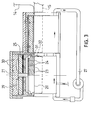
- FIG. 3 there is schematically shown a "positiv" mould tray 20'.
- the mould tray and the form (forms) for forming of cavities in the lower web may be arranged with extensions 31 and cut-outs 32.
- the mould tray is vertically movable. In connection herewith it may also be of interest to supply gas to the product that is packed.
Abstract
Description
- The present invention relates to a method of packaging products in roller operated packaging machines of the thermoforming type and an arrangement in such machines for carrying out the method. By the term roller operated packaging machine is meant a machine where a pair of webs, usually foils of plastics or laminates of plastics, are used for in-line filling and forming of a complete package.
- The problem behind the invention is to provide an improved packaging method in a roller operated machine.
- The problem is also related to the provision of an advantageous alternative to the fold free contour tight packaging method obtainable in packaging machines of the chamber type.
- The term chamber machine means a machine where a pouch with the contents thereof is loaded into a vacuum chamber for sealing and shrinking the pouch into a contour tight shape.
- Basically, it is also known to pack contour tight between webs. Goods to be packed, for instance for products such as pieces of meat, are placed between a planar heat shrinkable upper web and a lower thermoformable web having cavities formed therein. After having sealed the webs together after creating a vacuum, the upper web is'melted by heat transfer. The melting effect is such that the upper web falls down onto the product which will be enclosed contour tight between the webs without folds.
- As such, the known methods give a proper end product from a chamber machine and a roller operated machine, respectively. However, there are some short-comings. It is desirable to be able to provide a broader forming and filling range and offer a more form stable, rigid packaging construction compared to what is obtainable by the known methods. By forming and filling range is meant a range not restricting the forming depth and filling degree to very strict intervals, especially when a true contour tight package is desired.
- The object of the present invention is to provide a packaging method and a machinery which do not have the short-comings of known methods and machines.
- In the broadest sense thereof the invention provides a method of providing a sealed package from a pair of material webs in a roller operated packaging machine. The method comprises the steps of:
- thermoforming upwardly open cavities in a first web of a thermoformable material,
- filling the cavities with a product to be packed, thermoforming second cavities in a second web of a thermoformable material,
- form stabilizing said second cavities,
- bringing the product into contact with said second cavities first after said stabilization, and
- sealing the webs together such that pairs of cavities in the first and the second web, respectively, form a completed package, where the form stabilized cavity is the product supporting part of the package.
- In the preferred embodiment the method comprises the additional steps of:
- thermoforming second cavities in said second web in at least one mould tray in a tool,
- and heat-sealing each cavity around the margin thereof by said first web in the same mould tray by means of a sealing tool which at least partly surrounds the mould tray.
- Advantageously, the preferred method also includes the steps of:
- heating the second web to the forming temperature thereof before it is supplied to the mould tray, and
- cooling the mould tray to a temperature for form stabilization of the cavity,
- In one version the cooling of the mould tray is such that the marginal region assumes a higher temperature than the rest of the tray.
- A preferable temperature distribution may be realized by for instance intensifying the heat radiation between the sealing tool and the mould tray in the marginal region.
- In order to realize the desired end result the lower web is formed to a substantially product contour tight form by creating a vacuum in the region between the webs in combination with heat, preferably contact heat and/or a hot fluid, possibly supported by an external over-pressure.
- Preferably there are such arrangements that the marginal region of the mould tray is heated by radiation and/or convection from the sealing tool.
- The arrangement according to the invention for carrying out a method of forming a sealed package from a pair of material webs in a roller operated packaging machine comprises:
- a forming tool having at least one mould tray for thermoforming a cavity in one of said material webs of
- a thermoformable material,
- a sealing tool surrounding said tray for sealing of the marginal region of said pair of material webs surrounding said tray, and
- cooling channels arranged in the mould tray for providing a form stabilization environment.
-
- Figure 1 is a schematic longitudinal section through a part of a device for carrying out the method,
- Figure 2 is a cross-section through the part in Figure 1, and
- Figure 3 schematically shows another type of forming operation, positiv forming, in the upper web.
- In a preferred embodiment the mould tray and the sealing tool are arranged for operating on the upper web.
- In a
stand 10 there is supported a forming andvacuum unit 11. Basically theunit 11 comprises a fixed part 12 (may be movable when larger forming depth are required) and a verticallymovable part 13. A thermoformableupper web 14 andlower web 15, also thermoformable, are fed to theunit 11 in the direction of thearrows 16 and 17, respectively, when themovable part 13 is in the lower position thereof (not shown). The upper web is of a plastics material having enough thermoforming ability and sufficient strength characteristics for acting as the product supporting part of the package after the forming operation. - The
upper web 14 for instance consists of a PVC-web or a laminate based on PVC. - The
lower web 15 is of a well heat shrinkable material, for instance a laminate of polyamide and an ionomer, having cavities formed in advance (in the machine), as schematically indicated in Figure 1. - The
upper web 14 is heated to a suitable forming temperature in apre-heating unit 18 attached to thestand 10. Thelower part 19 of the unit is attached to themovable part 13 and may be provided with a heat supplying arrangement, for instance heating coils, for pre-heating of the already formed cavities (in the lower web 15) in order to facilitate a "shrinking operation" of the lower web but also of the marginal portions of the cavities in the upper web (as will be discussed later on). - There is a
mould tray 20 in thefixed part 12 and in the embodiment shown said tray is rigidly attached to thecooling plate 21 of asealing tool 22. Basically thecooling plate 21 is of the same type as plates normally found in sealing tools of roller operated machines, and the function thereof is to cool the air flow that attacks the marginal areas of thewebs welding plate 22, after the webs have been pressed together by the welding plate and thepart 13, and when the forming chamber comprising theparts - The cavity (shown by broken lines) pre-formed in the lower web arrives in the
movable part 13. After theparts upper web 14 starts. Themould tray 20 is provided with a number ofpassages 23 which now are brought into communication with a vacuum source. In the mould tray there are alsocooling channels 24 that communicate with a source of cooling medium, in this particular case water. When the upper web abuts the mould tray there will be a cooling effect which is controlled by a proper circulation of water. The result will be a form stable upper part. However, thewelding plate 22 is now hot (heating from the heating coils 25) meaning super-position of primarily radiation heat on the cooling from the water. The wall thickness of the tray that has been shown on the drawings and also the wall thicknes of the welding plate and the distance between the tray and the plate will create atransfer zone 26 heat/cold in the marginal region of the tray when there is a certin circulation rate of water. - This transfer zone plays an interesting role when forming (after-forming) the cavity in the lower web and the marginal portion of the upper web into a fold free/product contour tight shape.
- The effect normally used when thermoforming for providing such shrinking (after-forming) originates from the very fact that the heat supply returns a previously, at under-temperature, formed cavity to the original shape thereof. The term under-temperature means a temperature where the molecule orientation (memory of the material) is not lost.
- In the embodiment that has been shown the
lower part 13 supplies contact heat when the cavity (preferably formed at under-temperature at the very beginning) is sucked down (there are suction channels, not shown, in the lower part). However, instead of contact heat or in combination therewith, a hot fluid, for instance air, may be brought into contact with the web through aclosed circulation system 27. - The heat from the
lower part 13 and/or thesystem 27 in combination with the hotmarginal zone 23 of themould tray 20 provides the heat energy necessary for the shrinkage (after-forming). This forming may additionally vary in the marginal region (also as to extension) as well as in the lower web. However, the type of material used for the lower web is of importance, especially when larger forming depths are required. A suitable material is a laminate of polyamide and an ionomen. Also when the product to be packed does not fill the available total "packaging area" fully, a lower web having a high shrinkage characteristics is preferable. The term packaging area means the available goods supporting area of each package comprising a "lower" shrinkable film and a form stabilized "upper" tray. - The
welding plate 22 is operated by apressure plate 28. This plate is manipulated in a manner known per see by amembrane chamber 29 operated by pressurized fluid and provided in the cooling plate having cooling channels. - In Figure 2 there is shown in cross-section three
mould trays 20 and the welding plates, etc. thereof in the particular case where the web width corresponds to the width of three mould trays. - The manner in which the vacuum forming takes place in the
unit 11 is the normal one within the field and there is no need for a detailed description. However, it may be mentioned that the pressure is reset in the chamber formed byparts - In Figure 3 there is schematically shown a "positiv" mould tray 20'. The mould tray and the form (forms) for forming of cavities in the lower web may be arranged with
extensions 31 and cut-outs 32. In this particular case the mould tray is vertically movable. In connection herewith it may also be of interest to supply gas to the product that is packed.
Claims (10)
Applications Claiming Priority (2)
| Application Number | Priority Date | Filing Date | Title |
|---|---|---|---|
| SE8305356A SE455695B (en) | 1983-09-30 | 1983-09-30 | PACKAGING PROCEDURE AND PROCEDURE FOR IMPLEMENTATION OF THE PROCEDURE |
| SE8305356 | 1983-09-30 |
Publications (2)
| Publication Number | Publication Date |
|---|---|
| EP0136992A2 true EP0136992A2 (en) | 1985-04-10 |
| EP0136992A3 EP0136992A3 (en) | 1985-05-15 |
Family
ID=20352705
Family Applications (1)
| Application Number | Title | Priority Date | Filing Date |
|---|---|---|---|
| EP84850279A Ceased EP0136992A3 (en) | 1983-09-30 | 1984-09-21 | A packaging method and a device therefor |
Country Status (7)
| Country | Link |
|---|---|
| US (1) | US4676049A (en) |
| EP (1) | EP0136992A3 (en) |
| JP (1) | JPS6090106A (en) |
| DK (1) | DK430684A (en) |
| FI (1) | FI76750C (en) |
| NO (1) | NO843382L (en) |
| SE (1) | SE455695B (en) |
Cited By (1)
| Publication number | Priority date | Publication date | Assignee | Title |
|---|---|---|---|---|
| DE102014016833A1 (en) * | 2014-02-11 | 2015-08-27 | Multivac Sepp Haggenmüller Gmbh & Co. Kg | Sealing tool shell of a tray sealing machine |
Families Citing this family (4)
| Publication number | Priority date | Publication date | Assignee | Title |
|---|---|---|---|---|
| GB2197289B (en) * | 1986-11-14 | 1990-06-06 | Grace W R & Co | Method and apparatus for vacuum packaging |
| US5813193A (en) * | 1997-03-24 | 1998-09-29 | Owens-Illinois Labels Inc. | Method and apparatus for applying carriers to containers |
| DE10227610A1 (en) * | 2002-06-20 | 2004-01-15 | Multivac Sepp Haggenmüller GmbH & Co. | Packaging method and apparatus |
| DE102016123569A1 (en) * | 2016-12-06 | 2018-06-07 | Multivac Sepp Haggenmüller Se & Co. Kg | Tray sealing machine |
Citations (1)
| Publication number | Priority date | Publication date | Assignee | Title |
|---|---|---|---|---|
| US3545163A (en) * | 1969-07-30 | 1970-12-08 | Mahaffy & Harder Eng Co | Package forming methods and apparatus |
Family Cites Families (8)
| Publication number | Priority date | Publication date | Assignee | Title |
|---|---|---|---|---|
| US2958168A (en) * | 1959-05-19 | 1960-11-01 | Clarence W Vogt | Forming and filling containers |
| US3383260A (en) * | 1965-04-26 | 1968-05-14 | Mojonnier Inc Albert | Method and apparatus for heat sealing containers |
| DE2364565C2 (en) * | 1973-12-24 | 1983-01-05 | Multivac Sepp Haggenmüller KG, 8941 Wolfertschwenden | Method and vacuum packaging device for producing a package |
| US4034536A (en) * | 1976-06-11 | 1977-07-12 | Mahaffy & Harder Engineering Company | Packaging apparatus and techniques |
| US4294056A (en) * | 1978-10-04 | 1981-10-13 | Ralf Paulsen | Vacuum packaging machine |
| DE2930963C2 (en) * | 1979-07-31 | 1984-01-12 | Krämer & Grebe GmbH & Co KG Maschinen- und Modellfabrik, 3560 Biedenkopf | Packaging device |
| JPS5741122U (en) * | 1980-08-21 | 1982-03-05 | ||
| JPS5830927A (en) * | 1981-08-06 | 1983-02-23 | 住友ベークライト株式会社 | Method of sealing or externally packing bread-like body |
-
1983
- 1983-09-30 SE SE8305356A patent/SE455695B/en not_active IP Right Cessation
-
1984
- 1984-08-24 NO NO843382A patent/NO843382L/en unknown
- 1984-08-31 FI FI843432A patent/FI76750C/en not_active IP Right Cessation
- 1984-09-07 DK DK430684A patent/DK430684A/en not_active Application Discontinuation
- 1984-09-18 US US06/651,797 patent/US4676049A/en not_active Expired - Fee Related
- 1984-09-21 EP EP84850279A patent/EP0136992A3/en not_active Ceased
- 1984-09-28 JP JP59202170A patent/JPS6090106A/en active Pending
Patent Citations (1)
| Publication number | Priority date | Publication date | Assignee | Title |
|---|---|---|---|---|
| US3545163A (en) * | 1969-07-30 | 1970-12-08 | Mahaffy & Harder Eng Co | Package forming methods and apparatus |
Cited By (1)
| Publication number | Priority date | Publication date | Assignee | Title |
|---|---|---|---|---|
| DE102014016833A1 (en) * | 2014-02-11 | 2015-08-27 | Multivac Sepp Haggenmüller Gmbh & Co. Kg | Sealing tool shell of a tray sealing machine |
Also Published As
| Publication number | Publication date |
|---|---|
| NO843382L (en) | 1985-04-01 |
| FI76750B (en) | 1988-08-31 |
| FI76750C (en) | 1988-12-12 |
| SE8305356L (en) | 1985-03-31 |
| DK430684D0 (en) | 1984-09-07 |
| EP0136992A3 (en) | 1985-05-15 |
| SE455695B (en) | 1988-08-01 |
| FI843432A (en) | 1985-04-01 |
| JPS6090106A (en) | 1985-05-21 |
| FI843432A0 (en) | 1984-08-31 |
| DK430684A (en) | 1985-03-31 |
| US4676049A (en) | 1987-06-30 |
| SE8305356D0 (en) | 1983-09-30 |
Similar Documents
| Publication | Publication Date | Title |
|---|---|---|
| US20090007524A1 (en) | Device for Producing Deep Packaging Trays Comprising a Cooled Lower Mould Section | |
| US4229927A (en) | Process and apparatus for vacuum packing | |
| US3956867A (en) | Method of producing a package | |
| US3545163A (en) | Package forming methods and apparatus | |
| US4201030A (en) | Packaging apparatus and techniques for forming closure tops | |
| US5105603A (en) | Packaging machine for producing a reclosable package for a product | |
| US3695900A (en) | Evacuated hermetically sealed package with semirigid shell and stretchable closure | |
| US20030196412A1 (en) | Top formed packaging | |
| US20140331611A1 (en) | Packaging machine with a combined shaping and sealing tool | |
| KR960014545B1 (en) | Method and apparatus for pip pocket formation | |
| US4676049A (en) | Packaging method and a device therefore | |
| KR920002115B1 (en) | Casting method | |
| EP0055082A2 (en) | Thermoformed articles | |
| US3358900A (en) | Packaging | |
| US3933563A (en) | Method of severing and edge-sealing thermoplastic sets of films | |
| EP0321495B1 (en) | Food packaging with gas between tensioned film and lid | |
| EP0176514A1 (en) | Packaging foodstuffs. | |
| CA1086206A (en) | Process and apparatus for vacuum packing | |
| JP2006069548A (en) | High-speed vacuum individual packaging method for portion of meat | |
| AU572175B2 (en) | Improved packaging | |
| ITMO990288A1 (en) | CONTAINER FORMING SYSTEM FOR INJECTION OF A FORMING FLUID BETWEEN PARTS OF SHEET MATERIAL | |
| RU2406665C2 (en) | Packing machine for production of shrink packages and method of producing packages by thermal sealing of package container by top film | |
| CA1095396A (en) | Packaging apparatus and techniques for forming closure tops | |
| JPH0615730A (en) | Molding device | |
| GB1315126A (en) | Method of and means for the wrapping and packaging of books |
Legal Events
| Date | Code | Title | Description |
|---|---|---|---|
| PUAI | Public reference made under article 153(3) epc to a published international application that has entered the european phase |
Free format text: ORIGINAL CODE: 0009012 |
|
| PUAL | Search report despatched |
Free format text: ORIGINAL CODE: 0009013 |
|
| AK | Designated contracting states |
Designated state(s): AT BE CH DE FR GB IT LI LU NL |
|
| AK | Designated contracting states |
Designated state(s): AT BE CH DE FR GB IT LI LU NL |
|
| 17P | Request for examination filed |
Effective date: 19851108 |
|
| 17Q | First examination report despatched |
Effective date: 19860611 |
|
| STAA | Information on the status of an ep patent application or granted ep patent |
Free format text: STATUS: THE APPLICATION HAS BEEN REFUSED |
|
| 18R | Application refused |
Effective date: 19870925 |
|
| RIN1 | Information on inventor provided before grant (corrected) |
Inventor name: LINDSTAM, GOERAN Inventor name: WALLTER, GOETE |