EP0137975A2 - Blood lancet assembly - Google Patents
Blood lancet assembly Download PDFInfo
- Publication number
- EP0137975A2 EP0137975A2 EP84109934A EP84109934A EP0137975A2 EP 0137975 A2 EP0137975 A2 EP 0137975A2 EP 84109934 A EP84109934 A EP 84109934A EP 84109934 A EP84109934 A EP 84109934A EP 0137975 A2 EP0137975 A2 EP 0137975A2
- Authority
- EP
- European Patent Office
- Prior art keywords
- lancet
- shield
- handle
- receptacle
- assembly
- Prior art date
- Legal status (The legal status is an assumption and is not a legal conclusion. Google has not performed a legal analysis and makes no representation as to the accuracy of the status listed.)
- Granted
Links
Images


Classifications
-
- A—HUMAN NECESSITIES
- A61—MEDICAL OR VETERINARY SCIENCE; HYGIENE
- A61B—DIAGNOSIS; SURGERY; IDENTIFICATION
- A61B5/00—Measuring for diagnostic purposes; Identification of persons
- A61B5/15—Devices for taking samples of blood
- A61B5/151—Devices specially adapted for taking samples of capillary blood, e.g. by lancets, needles or blades
- A61B5/15142—Devices intended for single use, i.e. disposable
-
- A—HUMAN NECESSITIES
- A61—MEDICAL OR VETERINARY SCIENCE; HYGIENE
- A61B—DIAGNOSIS; SURGERY; IDENTIFICATION
- A61B5/00—Measuring for diagnostic purposes; Identification of persons
- A61B5/15—Devices for taking samples of blood
- A61B5/150007—Details
- A61B5/150015—Source of blood
- A61B5/150022—Source of blood for capillary blood or interstitial fluid
-
- A—HUMAN NECESSITIES
- A61—MEDICAL OR VETERINARY SCIENCE; HYGIENE
- A61B—DIAGNOSIS; SURGERY; IDENTIFICATION
- A61B5/00—Measuring for diagnostic purposes; Identification of persons
- A61B5/15—Devices for taking samples of blood
- A61B5/150007—Details
- A61B5/150374—Details of piercing elements or protective means for preventing accidental injuries by such piercing elements
- A61B5/150381—Design of piercing elements
- A61B5/150412—Pointed piercing elements, e.g. needles, lancets for piercing the skin
- A61B5/150427—Specific tip design, e.g. for improved penetration characteristics
-
- A—HUMAN NECESSITIES
- A61—MEDICAL OR VETERINARY SCIENCE; HYGIENE
- A61B—DIAGNOSIS; SURGERY; IDENTIFICATION
- A61B5/00—Measuring for diagnostic purposes; Identification of persons
- A61B5/15—Devices for taking samples of blood
- A61B5/151—Devices specially adapted for taking samples of capillary blood, e.g. by lancets, needles or blades
- A61B5/15101—Details
- A61B5/15103—Piercing procedure
- A61B5/15105—Purely manual piercing, i.e. the user pierces the skin without the assistance of any driving means or driving devices
Definitions
- the present invention relates to a blood lancet assembly and more particularly relates to a blood lancet assembly for penetrating living flesh to provide capillary blood for testing.
- a hypodermic needle has ground surfaces that cut and slice through the flesh while the typical planar lancet point has more of a tendency to puncture, stretch and tear the skin surrounding the puncture area. Also, most hypodermic needles are lubricated to reduce pain and insertion forces. Hypodermic needles are usually produced as an assembly with a rigid needle shield which engages the needle hub and protects the needle point from potential damage during shipping storage and final delivery to the user.
- hypodermic needle has a lumen for the delivery of medication. At the areas where the surface of the lumen intersects the planes of the ground point, there are formed sharp edges that can actually cut pieces of flesh away as the needle penetrates the flesh. This is undesirable in a lancet application since the removal of flesh will probably increase the amount of time needed for the puncture site to heal.
- Higgins teaches an integral lancet and package wherein a retainer section and a cap are integrally molded around the lancet covering all surfaces of the lancet point.
- the integral retainer and cap contains a reduced cross-sectional area portion at the intersection of the retainer and the cap so that rotation of the cap will sever the cap from the retainer section and allow exposure of the lancet point for use.
- a sterilization process, according to Higgins, is unnecessary since the elevated temperature of the molten plastic, during the molding process, completely sterilizes the point and adjacent surfaces of the lancet.
- Higgins' improvement lies in a rigid cover for the lancet point to protect it during handling. Also, when a flexible package containing a sterile lancet is torn or damaged, the lancet may become contaminated before use. Higgins' rigid package would appear to be more resistant to damage before use and therefore, offers improved protection. Also, with Higgins' integral lancet and package, it is not necessary to pull the lancet out of the package and to risk contamination of the point while doing so.
- the integral lancet and package of Higgins has numerous deficiencies. Most noteworthy is that the cap is molded around the lancet point. With this structure, unless the lancet point is symmetric around the longitudinal axis of the lancet, rotation of the cap relative to the lancet point could cause the lancet point to be deflected or damaged by the plastic cap or cause the lancet to cut through the adjacent cap material. The sharper the lancet cutting edges are, the more fragile they are, and the more likely they will be damaged by cap removal. In addition to apparently precluding 'the use of very sharp edges on the lancet, the Higgins lancet is not readily lubricated because the point is subsequently placed in contact with molten plastic.
- the Higgins' lancet point cannot be inspected after assembly into the retainer section. Therefore, any point damage that occurs during the molding procedure will go unnoticed and a potentially defective product will be transmitted to the user. Further, after using a lancet, it is desirable that the point of the lancet be re - covered in order to prevent contamination and/or infection that may result from someone being accidentally cut with the used lancet point. Higgins does not rely on this feature, and the fact that material is destroyed in order to remove the cap suggests that the cap may not stay on the lancet tip if it is repositioned thereon. Finally, the exterior surface of the reduced cross-sectional area in the Higgins device is not sterile and may contact the user's skin during use. This contact by a non-sterile surface can potentially deposit bacteria on the user's skin adjacent to the point of lancet penetration.
- the blood lancet assembly of the present invention comprises a handle having a distal end and a proximal end to be held by the user.
- a lancet extends outwardly from the distal end of the handle and terminates in a forward end adapted to cut living animal or human flesh.
- a shield having a open end, a closed end and a receptacle therein. This shield is removably engaged with the handle so that the forward end of the lancet is positioned within the receptacle of the shield.
- the receptacle is larger than the forward end of the lancet so that the lancet is maintained out of contact with the shield.
- a disposable blood lancet assembly comprises a lancet having a rearward end and a forward end shaped to form a point.
- the lancet point is formed by the intersection of three planes with each of said planes intersecting each other to form three cutting edges. These cutting edges originate at the outside surface of the lancet and terminate at the point.
- a handle has a proximal end adapted to be held by the user and a distal end connected to the rear end of the lancet so that the forward end of the lancet projects outwardly therefrom. Further, the distal end of the handle includes a raised portion having a side wall. This side wall surrounds the lancet and extends substantially parallel to the longitudinal axis of the lancet.
- a shield having an open end, a closed end and a preferably oblong receptacle therein.
- This receptacle is longer along its longitudinal axis than the portion of the lancet projecting outwardly from the handle.
- the shield is held in removable engagement with the handle by an interference fit between the side wall of the raised portion and the receptacle, wherein the forward end of the lancet is positioned within the receptacle.
- the shield is removable from the handle without touching the lancet and is replaceable on the handle after use of the lancet.
- the present invention provides a simple, straightforward, easily fabricated disposable blood lancet assembly.
- a sharp cutting point is provided which may be lubricated and inspected during the assembly process.
- the present lancet assembly includes a rigid package to protect the cutting point before use, wherein the removal of the rigid package should not damage or compromise the cutting point.
- a disposable blood lancet assembly 20 includes a cylindrically shaped lancet 21 having a rearward end 22 and a forward end 24 shaped to form a point 25. Also included is a handle 26 having a planar proximal end 27 and distal end 29. Projecting inwardly into the handle from the distal end toward the proximal end is tubular recess 30 terminating at end 31. Lancet 21 is contained within the tubular recess so that its rearward end is adjacent to the end of the tubular recess. The lancet is held in place in the tubular recess preferably by epoxy 32.
- the distance between point 25 of the lancet and the distal end of raised portion 46 and/or epoxy 32 is the depth which the lancet can penetrate the user's flesh. Accordingly, the desired depth of penetration of the lancet can be controlled by controlling the above-mentioned distance in the design and manufacture of the lancet assembly.
- the handle is planar in configuration in order to provide adequate surface areas for the user to grasp the handle between his finger tips and to control the handle which in turn controls the position of the lancet tip.
- the desirability of this feature will become apparent hereinafter.
- the planar proximal end of the handle consists preferably of crossed ribs 34 and 35, perimeter ribs 36, 37 and 39, reduced thickness sections 40, 41, 42 and 44, and distal rib 45.
- the variations in thicknesses between the ribs and the reduced thickness sections provide an improved gripping surface over a smooth surface which may tend to become slippery.
- planar portion of the handle in the preferred embodiment may be compact in structure with a typical handle measuring approximately 0.3 inch (7.6 mm) wide, by 0.75 inch (19.1 mm) long by 0.1 inch (2.5 mm) thick at the perimeter ribs. Also, the reduced thickness sections lessen the amount of material required to form the handle and therefore the cost.
- cylindrically shaped raised portion 46 Projecting outwardly from distal rib 45 is cylindrically shaped raised portion 46 which includes circular side wall 49 which surrounds the lancet and is substantially parallel to the longitudinal axis of the lancet.
- Assembly 20 further comprises a shield 50 having an open end 51, a closed end 52 and a receptacle 54 having a circularly shaped cross section.
- the shield is positioned over raised portion 46 and is held in removable engagement thereon.
- an interference fit is created at interface F between the receptacle surface and side wall 49, so that force must be applied to the shield to disengage it from the handle.
- the interference fit should be tight enough to keep the shield securely engaged to the handle and to protect the lancet from outside contamination without damaging the parts but must be loose enough to allow easy removal of the shield at the time of use. It should be noted that portions of raised portion 46 will touch the user's skin during use of the lancet assembly.
- annular end flange 55 has circumferencially oriented scallops 56.
- receptacle 54 is preferably longer along its longitudinal axis than the portion of the lancet projecting outwardly from the handle and that the receptacle has a larger inside diameter than the outside diameter of the lancet. This clearance between the lancet at the shield allows the shield to be removed and replaced without touching and possibly damaging the lancet point.
- Figs. 6 through 9 depict preferred lancet point 25, as part of the lancet of the present invention.
- This point is formed by the intersection of planes 59, 60 and 61.
- the lines of intersection between the planes form cutting edges 64, 65 and 66.
- Each cutting edge originates at the lancet outside diameter 57 and terminates at leading edge 62 of the point.
- planes 59,60 and 61 are all at the same angle, angle A, with respect to the longitudinal axis of lancet 21. In the preferred embodiment, angle A is approximately 12°.
- the planes are oriented so that cutting edges 64,65 and 66 intersect and form a point having leading edge 62 approximately at longitudinal axis 63 of the lancet. This point, with its leading edge approximately at the longitudinal axis, is called an axial point.
- the cutting edges act as sharp flesh cutting surfaces which cut as the lancet penetrates the skin.
- a circular point without cutting edges and a sheet metal lancet without ground edges would have a tendency to puncture, stretch and tear the skin as it penetrates producing what is believed to be a more painful incision.
- a three cutting edge point makes three cuts which can sever capillaries to produce blood while the well-known planar lancet only makes two cuts. Therefore, a two cutting edge lancet would have to make a larger incision to sever the same area of flesh, and produce the same amount of blood, as the preferred point. Accordingly, the preferred axial point is believed to reduce pain and trauma by producing the same amount of blood with a smaller incision.
- the preferred lancet does not include a lumen with surfaces which can intersect with the planes of the point to form interior cutting edges which can potentially cut away pieces of flesh during penetration.
- the present invention also allows the use of a medical grade silicone lubricant on the lancet point. It is known that this lubricant aids in reducing the forces required for the lancet to penetrate the skin and also the pain perceived by the user. Because shield 50 does not touch the lancet, the lubricant will not be removed or compromised by the act of removing the shield. Along the same lines, the fact that the shield does not touch the lancet allows the edges on the point to be extremely sharp and delicate since they will not be damaged by the removal of the shield.
- the shield is not installed until the handle and lancet are assembled.
- This sequence provides a further advantage in that the point of the lancet may be inspected for any damage that might have occurred during assembly before the shield is installed. Accordingly, a defective product may be eliminated before shipment from the manufacturer.
- the user firmly grasps handle 26 with the fingers of one hand and shield 50 in the area of the scallops with the fingers of the other hand. Then the user applies a rotational force to the shield, along with a pulling force, to remove the shield from the raised portion of the handle in order to expose the sharp lancet.
- the lancet is then quickly thrust toward and into the area of the body where the blood sample is to be taken and promptly removed to allow the blood to flow from the severed capillaries.
- the shield may then be reinstalled on the handle to cover the lancet and to prevent accidental cuts or infection which may result from inadvertent contact with the exposed lancet.
- the used lancet assembly is then discarded.
- thermoplastic materials such as polypropylene and polyethylene are preferred.
- the choice of epoxy formulation is dictated by the materials and processing conditions chosen for handle and lancet. It is preferred that the lancet be made of medical grade stainless steel unless the handle and the lancet are made in one piece. In the latter case, thermoplastic materials such as ABS, polypropylene and polystyrene are preferred. It is also desirable to apply a medical grade lubricant, such as medical grade silicone lubricant, to the portion of the lancet projecting outwardly from the handle. It is preferred that the lancet should be sterile when used. Accordingly, the materials for all components should be selected for compatability with the sterilization process.
- the present invention provides a simple, straight-forward, easily fabricated disposable blood lancet assembly which provides a sharp cutting point which may be lubricated and inspected during the assembly process. Also provided is a rigid shield to protect the cutting point, the lubricant thereon and a portion of the structure surrounding the lancet, before use.
- the present invention futher allows the removal of the shield without damaging or compromising the cutting point, and allows the subsequent reinstallation of the shield to protect against contamination and accidental cutting.
Abstract
Description
- 1. Field of the Invention. The present invention relates to a blood lancet assembly and more particularly relates to a blood lancet assembly for penetrating living flesh to provide capillary blood for testing.
- 2. Description of the Prior Art. It is common procedure in hospitals, clinics and doctor's offices to perform tests on blood provided by cutting or puncturing the skin and causing the capillaries of the patient to bleed. The instrument used to cut the capillaries is called a lancet. Lancets are commonly manufactured by stamping and forming the lancet from a sheet metal strip and then sealing it in a flexible package befored sterilizing. The lancet typically includes a shank portion which is formed to produce corregations or ribs, to facilitate holding the lancet, and a planar V-shaped cutting portion. A lancet of this type is shown in U.S. Patent No. 3,046,987 to Ehrlich.
- Although efficient for producing capillary blood, the lancet at times causes the user pain and produces more blood than is necessary for some tests. Lay people who have experienced both a hypodermic injection and a lancet puncture for a blood test will usually recite that the lancet is more painful. There are several reasons accounting for the increased pain produced by a lancet. First, a hypodermic needle has ground surfaces that cut and slice through the flesh while the typical planar lancet point has more of a tendency to puncture, stretch and tear the skin surrounding the puncture area. Also, most hypodermic needles are lubricated to reduce pain and insertion forces. Hypodermic needles are usually produced as an assembly with a rigid needle shield which engages the needle hub and protects the needle point from potential damage during shipping storage and final delivery to the user.
- One disadvantage to the hypodermic needle is that it has a lumen for the delivery of medication. At the areas where the surface of the lumen intersects the planes of the ground point, there are formed sharp edges that can actually cut pieces of flesh away as the needle penetrates the flesh. This is undesirable in a lancet application since the removal of flesh will probably increase the amount of time needed for the puncture site to heal.
- An improved lancet design is described in U.S. Patent No. 3,358,689 to Higgins. Higgins teaches an integral lancet and package wherein a retainer section and a cap are integrally molded around the lancet covering all surfaces of the lancet point. The integral retainer and cap contains a reduced cross-sectional area portion at the intersection of the retainer and the cap so that rotation of the cap will sever the cap from the retainer section and allow exposure of the lancet point for use. A sterilization process, according to Higgins, is unnecessary since the elevated temperature of the molten plastic, during the molding process, completely sterilizes the point and adjacent surfaces of the lancet.
- Higgins' improvement lies in a rigid cover for the lancet point to protect it during handling. Also, when a flexible package containing a sterile lancet is torn or damaged, the lancet may become contaminated before use. Higgins' rigid package would appear to be more resistant to damage before use and therefore, offers improved protection. Also, with Higgins' integral lancet and package, it is not necessary to pull the lancet out of the package and to risk contamination of the point while doing so.
- Nevertheless the integral lancet and package of Higgins has numerous deficiencies. Most noteworthy is that the cap is molded around the lancet point. With this structure, unless the lancet point is symmetric around the longitudinal axis of the lancet, rotation of the cap relative to the lancet point could cause the lancet point to be deflected or damaged by the plastic cap or cause the lancet to cut through the adjacent cap material. The sharper the lancet cutting edges are, the more fragile they are, and the more likely they will be damaged by cap removal. In addition to apparently precluding 'the use of very sharp edges on the lancet, the Higgins lancet is not readily lubricated because the point is subsequently placed in contact with molten plastic. Also, the Higgins' lancet point cannot be inspected after assembly into the retainer section. Therefore, any point damage that occurs during the molding procedure will go unnoticed and a potentially defective product will be transmitted to the user. Further, after using a lancet, it is desirable that the point of the lancet be re-covered in order to prevent contamination and/or infection that may result from someone being accidentally cut with the used lancet point. Higgins does not rely on this feature, and the fact that material is destroyed in order to remove the cap suggests that the cap may not stay on the lancet tip if it is repositioned thereon. Finally, the exterior surface of the reduced cross-sectional area in the Higgins device is not sterile and may contact the user's skin during use. This contact by a non-sterile surface can potentially deposit bacteria on the user's skin adjacent to the point of lancet penetration.
- Although various forms of lancets have been addressed by the prior art, there is still a need for a simple, straight-forward, easily fabricated disposable blood lancet assembly which offers a sharp cutting point which may be lubricated and inspected during the assembly process and provides a rigid package to protect the cutting point before use wherein the removal of the rigid package will not damage or compromise the cutting point.
- The blood lancet assembly of the present invention comprises a handle having a distal end and a proximal end to be held by the user. A lancet extends outwardly from the distal end of the handle and terminates in a forward end adapted to cut living animal or human flesh. Also included is a shield having a open end, a closed end and a receptacle therein. This shield is removably engaged with the handle so that the forward end of the lancet is positioned within the receptacle of the shield. The receptacle is larger than the forward end of the lancet so that the lancet is maintained out of contact with the shield.
- In accordance with the preferred embodiment of the present invention, a disposable blood lancet assembly comprises a lancet having a rearward end and a forward end shaped to form a point. The lancet point is formed by the intersection of three planes with each of said planes intersecting each other to form three cutting edges. These cutting edges originate at the outside surface of the lancet and terminate at the point. A handle has a proximal end adapted to be held by the user and a distal end connected to the rear end of the lancet so that the forward end of the lancet projects outwardly therefrom. Further, the distal end of the handle includes a raised portion having a side wall. This side wall surrounds the lancet and extends substantially parallel to the longitudinal axis of the lancet. Also provided is a shield having an open end, a closed end and a preferably oblong receptacle therein. This receptacle is longer along its longitudinal axis than the portion of the lancet projecting outwardly from the handle. The shield is held in removable engagement with the handle by an interference fit between the side wall of the raised portion and the receptacle, wherein the forward end of the lancet is positioned within the receptacle. The shield is removable from the handle without touching the lancet and is replaceable on the handle after use of the lancet.
- In accordance with the principles of the present invention, a number of advantages and objectives are attained. Primarily, the present invention provides a simple, straightforward, easily fabricated disposable blood lancet assembly. A sharp cutting point is provided which may be lubricated and inspected during the assembly process. In addition the present lancet assembly includes a rigid package to protect the cutting point before use, wherein the removal of the rigid package should not damage or compromise the cutting point.
-
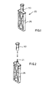
- Fig. 1 is a perspective view of the preferred disposable blood lancet assembly of the present invention;
- Fig. 2 is the blood lancet assembly of Fig. 1 illustrating the shield removed and separated from the handle;
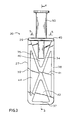
- Fig. 3 is an enlarged front elevation view of the preferred disposable blood lancet assembly;
- Fig. 4 is a cross-sectional view of the blood. lancet assembly of Fig. 3 taken along line 4-4;
- Fig. 5 is cross-sectional view of the blood lancet assembly of Fig. 3 taken along line 5-5;
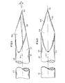
- Fig. 6 is an enlarged partial side elevation view of the lancet of the preferred disposable blood lancet assembly;
- Fig. 7 is a top plan view of the lancet of Fig. 6.
- Fig. 8 is an enlarged partial side elevation view of the lancet of the preferred disposable blood lancet assembly taken 90 degrees from the view of Fig. 6; and
- Fig. 9 is a top. plan view of the lancet of Fig. 8.
- While this invention is satisfied by embodiments in many different forms, there is shown in the drawings and will herein be described in detail preferred embodiments of the invention with the understanding that the present disclosure is to be considered as exemplary of the principles of the invention and is not intended to limit the invention to the embodiments illustrated. The scope of the invention will be measured by the appended claims and their equivalents.
- Adverting now to Figs. 1 through 5, a disposable
blood lancet assembly 20 includes a cylindrically shapedlancet 21 having arearward end 22 and aforward end 24 shaped to form apoint 25. Also included is ahandle 26 having a planarproximal end 27 anddistal end 29. Projecting inwardly into the handle from the distal end toward the proximal end istubular recess 30 terminating atend 31.Lancet 21 is contained within the tubular recess so that its rearward end is adjacent to the end of the tubular recess. The lancet is held in place in the tubular recess preferably byepoxy 32. It will be apparent to one skilled in the art that numerous constructions can be used to join the lancet and the handle and that the arrangement described above is exemplary of these many possibilities. Also, it is within the purview of this invention to include a one-piece lancet and handle assembly. - It should be noted that the distance between
point 25 of the lancet and the distal end of raisedportion 46 and/orepoxy 32 is the depth which the lancet can penetrate the user's flesh. Accordingly, the desired depth of penetration of the lancet can be controlled by controlling the above-mentioned distance in the design and manufacture of the lancet assembly. - The handle is planar in configuration in order to provide adequate surface areas for the user to grasp the handle between his finger tips and to control the handle which in turn controls the position of the lancet tip. The desirability of this feature will become apparent hereinafter. The planar proximal end of the handle consists preferably of crossed
ribs perimeter ribs thickness sections distal rib 45. The variations in thicknesses between the ribs and the reduced thickness sections provide an improved gripping surface over a smooth surface which may tend to become slippery. This is helpful since the planar portion of the handle in the preferred embodiment may be compact in structure with a typical handle measuring approximately 0.3 inch (7.6 mm) wide, by 0.75 inch (19.1 mm) long by 0.1 inch (2.5 mm) thick at the perimeter ribs. Also, the reduced thickness sections lessen the amount of material required to form the handle and therefore the cost. Projecting outwardly fromdistal rib 45 is cylindrically shaped raisedportion 46 which includescircular side wall 49 which surrounds the lancet and is substantially parallel to the longitudinal axis of the lancet. -
Assembly 20 further comprises ashield 50 having anopen end 51, aclosed end 52 and areceptacle 54 having a circularly shaped cross section. The shield is positioned over raisedportion 46 and is held in removable engagement thereon. By making the outside diameter of raisedportion 46 larger than the inside diameter ofreceptacle 54, an interference fit is created at interface F between the receptacle surface andside wall 49, so that force must be applied to the shield to disengage it from the handle. The interference fit should be tight enough to keep the shield securely engaged to the handle and to protect the lancet from outside contamination without damaging the parts but must be loose enough to allow easy removal of the shield at the time of use. It should be noted that portions of raisedportion 46 will touch the user's skin during use of the lancet assembly. However, potential for bacterial contamination of the lancet penetration site, by the raised portion, is reduced becauseshield 50 covers and protects raisedportion 46 from contamination after assembly. To facilitate the removal of the shield from the handle,annular end flange 55 has circumferencially orientedscallops 56. - It should be noted that
receptacle 54 is preferably longer along its longitudinal axis than the portion of the lancet projecting outwardly from the handle and that the receptacle has a larger inside diameter than the outside diameter of the lancet. This clearance between the lancet at the shield allows the shield to be removed and replaced without touching and possibly damaging the lancet point. - Figs. 6 through 9 depict preferred
lancet point 25, as part of the lancet of the present invention. This point is formed by the intersection ofplanes edges diameter 57 and terminates at leadingedge 62 of the point. Preferably, planes 59,60 and 61 are all at the same angle, angle A, with respect to the longitudinal axis oflancet 21. In the preferred embodiment, angle A is approximately 12°. Also, the planes are oriented so that cuttingedges edge 62 approximately atlongitudinal axis 63 of the lancet. This point, with its leading edge approximately at the longitudinal axis, is called an axial point. - The cutting edges act as sharp flesh cutting surfaces which cut as the lancet penetrates the skin. A circular point without cutting edges and a sheet metal lancet without ground edges would have a tendency to puncture, stretch and tear the skin as it penetrates producing what is believed to be a more painful incision. Further, a three cutting edge point makes three cuts which can sever capillaries to produce blood while the well-known planar lancet only makes two cuts. Therefore, a two cutting edge lancet would have to make a larger incision to sever the same area of flesh, and produce the same amount of blood, as the preferred point. Accordingly, the preferred axial point is believed to reduce pain and trauma by producing the same amount of blood with a smaller incision.
- Unlike a hypodermic needle, as discussed hereinabove, the preferred lancet does not include a lumen with surfaces which can intersect with the planes of the point to form interior cutting edges which can potentially cut away pieces of flesh during penetration.
- The present invention also allows the use of a medical grade silicone lubricant on the lancet point. It is known that this lubricant aids in reducing the forces required for the lancet to penetrate the skin and also the pain perceived by the user. Because
shield 50 does not touch the lancet, the lubricant will not be removed or compromised by the act of removing the shield. Along the same lines, the fact that the shield does not touch the lancet allows the edges on the point to be extremely sharp and delicate since they will not be damaged by the removal of the shield. - In the assembly of the instant invention, the shield is not installed until the handle and lancet are assembled. This sequence provides a further advantage in that the point of the lancet may be inspected for any damage that might have occurred during assembly before the shield is installed. Accordingly, a defective product may be eliminated before shipment from the manufacturer.
- In use, the user firmly grasps
handle 26 with the fingers of one hand andshield 50 in the area of the scallops with the fingers of the other hand. Then the user applies a rotational force to the shield, along with a pulling force, to remove the shield from the raised portion of the handle in order to expose the sharp lancet. The lancet is then quickly thrust toward and into the area of the body where the blood sample is to be taken and promptly removed to allow the blood to flow from the severed capillaries. The shield may then be reinstalled on the handle to cover the lancet and to prevent accidental cuts or infection which may result from inadvertent contact with the exposed lancet. The used lancet assembly is then discarded. - A wide variety of rigid materials is suitable for constructing the handle and shield, however, thermoplastic materials such as polypropylene and polyethylene are preferred. The choice of epoxy formulation is dictated by the materials and processing conditions chosen for handle and lancet. It is preferred that the lancet be made of medical grade stainless steel unless the handle and the lancet are made in one piece. In the latter case, thermoplastic materials such as ABS, polypropylene and polystyrene are preferred. It is also desirable to apply a medical grade lubricant, such as medical grade silicone lubricant, to the portion of the lancet projecting outwardly from the handle. It is preferred that the lancet should be sterile when used. Accordingly, the materials for all components should be selected for compatability with the sterilization process.
- Thus it can be seen that the present invention provides a simple, straight-forward, easily fabricated disposable blood lancet assembly which provides a sharp cutting point which may be lubricated and inspected during the assembly process. Also provided is a rigid shield to protect the cutting point, the lubricant thereon and a portion of the structure surrounding the lancet, before use. The present invention futher allows the removal of the shield without damaging or compromising the cutting point, and allows the subsequent reinstallation of the shield to protect against contamination and accidental cutting.
Claims (18)
Applications Claiming Priority (2)
| Application Number | Priority Date | Filing Date | Title |
|---|---|---|---|
| US53242383A | 1983-09-15 | 1983-09-15 | |
| US532423 | 1983-09-15 |
Publications (3)
| Publication Number | Publication Date |
|---|---|
| EP0137975A2 true EP0137975A2 (en) | 1985-04-24 |
| EP0137975A3 EP0137975A3 (en) | 1987-01-14 |
| EP0137975B1 EP0137975B1 (en) | 1990-10-24 |
Family
ID=24121717
Family Applications (1)
| Application Number | Title | Priority Date | Filing Date |
|---|---|---|---|
| EP84109934A Expired - Lifetime EP0137975B1 (en) | 1983-09-15 | 1984-08-21 | Blood lancet assembly |
Country Status (10)
| Country | Link |
|---|---|
| EP (1) | EP0137975B1 (en) |
| JP (1) | JPS6063040A (en) |
| AU (1) | AU564640B2 (en) |
| BR (1) | BR8402948A (en) |
| DE (1) | DE3483452D1 (en) |
| ES (1) | ES292499Y (en) |
| MX (1) | MX159428A (en) |
| MY (1) | MY100331A (en) |
| NZ (1) | NZ208203A (en) |
| ZA (1) | ZA844194B (en) |
Cited By (35)
| Publication number | Priority date | Publication date | Assignee | Title |
|---|---|---|---|---|
| EP0589186A1 (en) * | 1992-08-28 | 1994-03-30 | Apls Co., Ltd. | Lancet |
| EP0613656A2 (en) * | 1993-02-26 | 1994-09-07 | Becton, Dickinson and Company | Lancet blade designed for reduced pain |
| GB2330313A (en) * | 1997-10-14 | 1999-04-21 | Hewlett Packard Co | Blood sampling device |
| WO2007085865A1 (en) | 2006-01-27 | 2007-08-02 | Owen Mumford Limited | Lancet |
| US7311718B2 (en) | 1998-06-11 | 2007-12-25 | Stat Medical Devices Inc. | Lancet having adjustable penetration depth |
| US7621931B2 (en) | 2003-05-20 | 2009-11-24 | Stat Medical Devices, Inc. | Adjustable lancet device and method |
| US7651512B2 (en) | 1999-08-03 | 2010-01-26 | Becton, Dickinson And Company | Lancer |
| US8257380B2 (en) | 2004-06-29 | 2012-09-04 | Stat Medical Devices, Inc. | Adjustabable disposable/single-use lancet device and method |
| US8372103B2 (en) | 2006-01-12 | 2013-02-12 | Owen Mumford, Ltd. | Lancet firing device |
| US8690796B2 (en) | 2002-04-19 | 2014-04-08 | Sanofi-Aventis Deutschland Gmbh | Method and apparatus for penetrating tissue |
| US8709032B2 (en) | 2000-01-28 | 2014-04-29 | Stat Medical Devices, Inc. | Adjustable tip for a lancet device and method |
| US8845550B2 (en) | 2001-06-12 | 2014-09-30 | Sanofi-Aventis Deutschland Gmbh | Tissue penetration device |
| US8845549B2 (en) | 2002-04-19 | 2014-09-30 | Sanofi-Aventis Deutschland Gmbh | Method for penetrating tissue |
| US8905945B2 (en) | 2002-04-19 | 2014-12-09 | Dominique M. Freeman | Method and apparatus for penetrating tissue |
| US8945910B2 (en) | 2003-09-29 | 2015-02-03 | Sanofi-Aventis Deutschland Gmbh | Method and apparatus for an improved sample capture device |
| US8965476B2 (en) | 2010-04-16 | 2015-02-24 | Sanofi-Aventis Deutschland Gmbh | Tissue penetration device |
| US9089294B2 (en) | 2002-04-19 | 2015-07-28 | Sanofi-Aventis Deutschland Gmbh | Analyte measurement device with a single shot actuator |
| US9089678B2 (en) | 2002-04-19 | 2015-07-28 | Sanofi-Aventis Deutschland Gmbh | Method and apparatus for penetrating tissue |
| US9144401B2 (en) | 2003-06-11 | 2015-09-29 | Sanofi-Aventis Deutschland Gmbh | Low pain penetrating member |
| US9226699B2 (en) | 2002-04-19 | 2016-01-05 | Sanofi-Aventis Deutschland Gmbh | Body fluid sampling module with a continuous compression tissue interface surface |
| US9248267B2 (en) | 2002-04-19 | 2016-02-02 | Sanofi-Aventis Deustchland Gmbh | Tissue penetration device |
| US9261476B2 (en) | 2004-05-20 | 2016-02-16 | Sanofi Sa | Printable hydrogel for biosensors |
| US9314194B2 (en) | 2002-04-19 | 2016-04-19 | Sanofi-Aventis Deutschland Gmbh | Tissue penetration device |
| US9351680B2 (en) | 2003-10-14 | 2016-05-31 | Sanofi-Aventis Deutschland Gmbh | Method and apparatus for a variable user interface |
| US9375169B2 (en) | 2009-01-30 | 2016-06-28 | Sanofi-Aventis Deutschland Gmbh | Cam drive for managing disposable penetrating member actions with a single motor and motor and control system |
| US9386944B2 (en) | 2008-04-11 | 2016-07-12 | Sanofi-Aventis Deutschland Gmbh | Method and apparatus for analyte detecting device |
| US9427532B2 (en) | 2001-06-12 | 2016-08-30 | Sanofi-Aventis Deutschland Gmbh | Tissue penetration device |
| US9561000B2 (en) | 2003-12-31 | 2017-02-07 | Sanofi-Aventis Deutschland Gmbh | Method and apparatus for improving fluidic flow and sample capture |
| US9560993B2 (en) | 2001-11-21 | 2017-02-07 | Sanofi-Aventis Deutschland Gmbh | Blood testing apparatus having a rotatable cartridge with multiple lancing elements and testing means |
| US9775553B2 (en) | 2004-06-03 | 2017-10-03 | Sanofi-Aventis Deutschland Gmbh | Method and apparatus for a fluid sampling device |
| US9795747B2 (en) | 2010-06-02 | 2017-10-24 | Sanofi-Aventis Deutschland Gmbh | Methods and apparatus for lancet actuation |
| US9820684B2 (en) | 2004-06-03 | 2017-11-21 | Sanofi-Aventis Deutschland Gmbh | Method and apparatus for a fluid sampling device |
| US9839386B2 (en) | 2002-04-19 | 2017-12-12 | Sanofi-Aventis Deustschland Gmbh | Body fluid sampling device with capacitive sensor |
| US10070811B2 (en) | 2014-06-26 | 2018-09-11 | Stat Medical Devices, Inc. | Lancing device with depth adjustment and lancet removal system and method |
| US10307095B2 (en) | 2007-06-19 | 2019-06-04 | Stat Medical Devices, Inc. | Lancet device with depth adjustment and lancet removal system and method |
Families Citing this family (16)
| Publication number | Priority date | Publication date | Assignee | Title |
|---|---|---|---|---|
| NL8401536A (en) * | 1984-05-11 | 1985-12-02 | Medscan B V I O | BLOOD SAMPLING UNIT. |
| US4616649A (en) * | 1984-09-20 | 1986-10-14 | Becton, Dickinson And Company | Lancet |
| US5250066A (en) * | 1990-03-19 | 1993-10-05 | Becton Dickinson And Company | Plastic pointed articles and method for their preparation |
| DE19718081A1 (en) | 1997-04-29 | 1998-11-05 | Boehringer Mannheim Gmbh | Disposable blood lancet |
| JP4716475B2 (en) * | 2001-09-06 | 2011-07-06 | ヤンマー株式会社 | Agricultural machine |
| US7905898B2 (en) | 2003-08-15 | 2011-03-15 | Stat Medical Devices, Inc. | Adjustable lancet device and method |
| US7361182B2 (en) * | 2003-12-19 | 2008-04-22 | Lightnix, Inc. | Medical lancet |
| US8105347B2 (en) | 2004-11-16 | 2012-01-31 | Stat Medical Devices, Inc. | Adjustable disposable/single-use blade lancet device and method |
| US8066728B2 (en) | 2004-11-30 | 2011-11-29 | Stat Medical Devices, Inc. | Disposable or single-use lancet device and method |
| US9289161B2 (en) | 2005-01-28 | 2016-03-22 | Stat Medical Divices, Inc. | Multi-lancet unit, method and lancet device using the multi-lancet unit, and method of assembling and/or making the multi-lancet unit |
| US7704265B2 (en) | 2005-11-03 | 2010-04-27 | Stat Medical Devices, Inc. | Disposable/single-use blade lancet device and method |
| GB0524604D0 (en) | 2005-12-02 | 2006-01-11 | Owen Mumford Ltd | Injection method and apparatus |
| US8043318B2 (en) | 2007-02-08 | 2011-10-25 | Stat Medical Devices, Inc. | Push-button lance device and method |
| WO2008100818A1 (en) | 2007-02-09 | 2008-08-21 | Stat Medical Devices, Inc | Multi-lancet unit, method and lancet device using the multi-lancet unit, and method of assembling and/or making the multi-lancet unit |
| US8469986B2 (en) | 2007-03-30 | 2013-06-25 | Stat Medical Devices, Inc. | Lancet device with combined trigger and cocking mechanism and method |
| GB2465390A (en) | 2008-11-17 | 2010-05-19 | Owen Mumford Ltd | Syringe needle cover remover |
Citations (3)
| Publication number | Priority date | Publication date | Assignee | Title |
|---|---|---|---|---|
| GB1085141A (en) * | 1964-06-09 | 1967-09-27 | Roehr Products Company Inc | Integral lancet and package |
| FR2508305A1 (en) * | 1981-06-25 | 1982-12-31 | Slama Gerard | DEVICE FOR PROVOKING A SMALL SQUAD TO COLLECT A BLOOD DROP |
| EP0088257A1 (en) * | 1982-03-09 | 1983-09-14 | Werner Beiter | Blood lancet |
Family Cites Families (1)
| Publication number | Priority date | Publication date | Assignee | Title |
|---|---|---|---|---|
| JPS54106692U (en) * | 1978-06-16 | 1979-07-27 |
-
1984
- 1984-05-18 NZ NZ208203A patent/NZ208203A/en unknown
- 1984-05-21 AU AU28431/84A patent/AU564640B2/en not_active Ceased
- 1984-06-05 ZA ZA844194A patent/ZA844194B/en unknown
- 1984-06-14 ES ES1984292499U patent/ES292499Y/en not_active Expired
- 1984-06-15 BR BR8402948A patent/BR8402948A/en not_active IP Right Cessation
- 1984-07-10 JP JP59143190A patent/JPS6063040A/en active Granted
- 1984-07-23 MX MX202125A patent/MX159428A/en unknown
- 1984-08-21 DE DE8484109934T patent/DE3483452D1/en not_active Expired - Fee Related
- 1984-08-21 EP EP84109934A patent/EP0137975B1/en not_active Expired - Lifetime
-
1987
- 1987-09-29 MY MYPI87002173A patent/MY100331A/en unknown
Patent Citations (3)
| Publication number | Priority date | Publication date | Assignee | Title |
|---|---|---|---|---|
| GB1085141A (en) * | 1964-06-09 | 1967-09-27 | Roehr Products Company Inc | Integral lancet and package |
| FR2508305A1 (en) * | 1981-06-25 | 1982-12-31 | Slama Gerard | DEVICE FOR PROVOKING A SMALL SQUAD TO COLLECT A BLOOD DROP |
| EP0088257A1 (en) * | 1982-03-09 | 1983-09-14 | Werner Beiter | Blood lancet |
Cited By (51)
| Publication number | Priority date | Publication date | Assignee | Title |
|---|---|---|---|---|
| EP0589186A1 (en) * | 1992-08-28 | 1994-03-30 | Apls Co., Ltd. | Lancet |
| EP0613656A2 (en) * | 1993-02-26 | 1994-09-07 | Becton, Dickinson and Company | Lancet blade designed for reduced pain |
| EP0613656A3 (en) * | 1993-02-26 | 1998-04-01 | Becton, Dickinson and Company | Lancet blade designed for reduced pain |
| GB2330313A (en) * | 1997-10-14 | 1999-04-21 | Hewlett Packard Co | Blood sampling device |
| US5938679A (en) * | 1997-10-14 | 1999-08-17 | Hewlett-Packard Company | Apparatus and method for minimally invasive blood sampling |
| US7311718B2 (en) | 1998-06-11 | 2007-12-25 | Stat Medical Devices Inc. | Lancet having adjustable penetration depth |
| US7651512B2 (en) | 1999-08-03 | 2010-01-26 | Becton, Dickinson And Company | Lancer |
| US8777973B2 (en) | 1999-08-03 | 2014-07-15 | Becton, Dickinson And Company | Lancer |
| US8709032B2 (en) | 2000-01-28 | 2014-04-29 | Stat Medical Devices, Inc. | Adjustable tip for a lancet device and method |
| US8845550B2 (en) | 2001-06-12 | 2014-09-30 | Sanofi-Aventis Deutschland Gmbh | Tissue penetration device |
| US9802007B2 (en) | 2001-06-12 | 2017-10-31 | Sanofi-Aventis Deutschland Gmbh | Methods and apparatus for lancet actuation |
| US9694144B2 (en) | 2001-06-12 | 2017-07-04 | Sanofi-Aventis Deutschland Gmbh | Sampling module device and method |
| US9427532B2 (en) | 2001-06-12 | 2016-08-30 | Sanofi-Aventis Deutschland Gmbh | Tissue penetration device |
| US9937298B2 (en) | 2001-06-12 | 2018-04-10 | Sanofi-Aventis Deutschland Gmbh | Tissue penetration device |
| US9560993B2 (en) | 2001-11-21 | 2017-02-07 | Sanofi-Aventis Deutschland Gmbh | Blood testing apparatus having a rotatable cartridge with multiple lancing elements and testing means |
| US8690796B2 (en) | 2002-04-19 | 2014-04-08 | Sanofi-Aventis Deutschland Gmbh | Method and apparatus for penetrating tissue |
| US9186468B2 (en) | 2002-04-19 | 2015-11-17 | Sanofi-Aventis Deutschland Gmbh | Method and apparatus for penetrating tissue |
| US8905945B2 (en) | 2002-04-19 | 2014-12-09 | Dominique M. Freeman | Method and apparatus for penetrating tissue |
| US9498160B2 (en) | 2002-04-19 | 2016-11-22 | Sanofi-Aventis Deutschland Gmbh | Method for penetrating tissue |
| US9839386B2 (en) | 2002-04-19 | 2017-12-12 | Sanofi-Aventis Deustschland Gmbh | Body fluid sampling device with capacitive sensor |
| US9072842B2 (en) | 2002-04-19 | 2015-07-07 | Sanofi-Aventis Deutschland Gmbh | Method and apparatus for penetrating tissue |
| US9089294B2 (en) | 2002-04-19 | 2015-07-28 | Sanofi-Aventis Deutschland Gmbh | Analyte measurement device with a single shot actuator |
| US9089678B2 (en) | 2002-04-19 | 2015-07-28 | Sanofi-Aventis Deutschland Gmbh | Method and apparatus for penetrating tissue |
| US9795334B2 (en) | 2002-04-19 | 2017-10-24 | Sanofi-Aventis Deutschland Gmbh | Method and apparatus for penetrating tissue |
| US9724021B2 (en) | 2002-04-19 | 2017-08-08 | Sanofi-Aventis Deutschland Gmbh | Method and apparatus for penetrating tissue |
| US9226699B2 (en) | 2002-04-19 | 2016-01-05 | Sanofi-Aventis Deutschland Gmbh | Body fluid sampling module with a continuous compression tissue interface surface |
| US9248267B2 (en) | 2002-04-19 | 2016-02-02 | Sanofi-Aventis Deustchland Gmbh | Tissue penetration device |
| US8845549B2 (en) | 2002-04-19 | 2014-09-30 | Sanofi-Aventis Deutschland Gmbh | Method for penetrating tissue |
| US9314194B2 (en) | 2002-04-19 | 2016-04-19 | Sanofi-Aventis Deutschland Gmbh | Tissue penetration device |
| US9339612B2 (en) | 2002-04-19 | 2016-05-17 | Sanofi-Aventis Deutschland Gmbh | Tissue penetration device |
| US9907502B2 (en) | 2002-04-19 | 2018-03-06 | Sanofi-Aventis Deutschland Gmbh | Method and apparatus for penetrating tissue |
| US7621931B2 (en) | 2003-05-20 | 2009-11-24 | Stat Medical Devices, Inc. | Adjustable lancet device and method |
| US10034628B2 (en) | 2003-06-11 | 2018-07-31 | Sanofi-Aventis Deutschland Gmbh | Low pain penetrating member |
| US9144401B2 (en) | 2003-06-11 | 2015-09-29 | Sanofi-Aventis Deutschland Gmbh | Low pain penetrating member |
| US8945910B2 (en) | 2003-09-29 | 2015-02-03 | Sanofi-Aventis Deutschland Gmbh | Method and apparatus for an improved sample capture device |
| US9351680B2 (en) | 2003-10-14 | 2016-05-31 | Sanofi-Aventis Deutschland Gmbh | Method and apparatus for a variable user interface |
| US9561000B2 (en) | 2003-12-31 | 2017-02-07 | Sanofi-Aventis Deutschland Gmbh | Method and apparatus for improving fluidic flow and sample capture |
| US9261476B2 (en) | 2004-05-20 | 2016-02-16 | Sanofi Sa | Printable hydrogel for biosensors |
| US9775553B2 (en) | 2004-06-03 | 2017-10-03 | Sanofi-Aventis Deutschland Gmbh | Method and apparatus for a fluid sampling device |
| US9820684B2 (en) | 2004-06-03 | 2017-11-21 | Sanofi-Aventis Deutschland Gmbh | Method and apparatus for a fluid sampling device |
| US8257380B2 (en) | 2004-06-29 | 2012-09-04 | Stat Medical Devices, Inc. | Adjustabable disposable/single-use lancet device and method |
| US8372103B2 (en) | 2006-01-12 | 2013-02-12 | Owen Mumford, Ltd. | Lancet firing device |
| WO2007085865A1 (en) | 2006-01-27 | 2007-08-02 | Owen Mumford Limited | Lancet |
| US8603126B2 (en) | 2006-01-27 | 2013-12-10 | Owen Mumford Limited | Lancet |
| US10307095B2 (en) | 2007-06-19 | 2019-06-04 | Stat Medical Devices, Inc. | Lancet device with depth adjustment and lancet removal system and method |
| US9386944B2 (en) | 2008-04-11 | 2016-07-12 | Sanofi-Aventis Deutschland Gmbh | Method and apparatus for analyte detecting device |
| US9375169B2 (en) | 2009-01-30 | 2016-06-28 | Sanofi-Aventis Deutschland Gmbh | Cam drive for managing disposable penetrating member actions with a single motor and motor and control system |
| US8965476B2 (en) | 2010-04-16 | 2015-02-24 | Sanofi-Aventis Deutschland Gmbh | Tissue penetration device |
| US9795747B2 (en) | 2010-06-02 | 2017-10-24 | Sanofi-Aventis Deutschland Gmbh | Methods and apparatus for lancet actuation |
| US10070811B2 (en) | 2014-06-26 | 2018-09-11 | Stat Medical Devices, Inc. | Lancing device with depth adjustment and lancet removal system and method |
| US11071482B2 (en) | 2014-06-26 | 2021-07-27 | Stat Medical Devices, Inc. | Lancet device with depth adjustment and lancet removal system and method |
Also Published As
| Publication number | Publication date |
|---|---|
| EP0137975A3 (en) | 1987-01-14 |
| ES292499U (en) | 1986-06-01 |
| ES292499Y (en) | 1987-02-16 |
| EP0137975B1 (en) | 1990-10-24 |
| DE3483452D1 (en) | 1990-11-29 |
| JPS6063040A (en) | 1985-04-11 |
| MY100331A (en) | 1990-08-11 |
| NZ208203A (en) | 1988-03-30 |
| BR8402948A (en) | 1985-05-28 |
| JPH0236096B2 (en) | 1990-08-15 |
| AU564640B2 (en) | 1987-08-20 |
| MX159428A (en) | 1989-05-30 |
| ZA844194B (en) | 1985-01-30 |
| AU2843184A (en) | 1985-03-21 |
Similar Documents
| Publication | Publication Date | Title |
|---|---|---|
| EP0137975B1 (en) | Blood lancet assembly | |
| KR100685695B1 (en) | Lancet, set of lancets, lancet magazine, method for driving a lancet of a lancing device | |
| CA2093580C (en) | Lancet device for puncturing the skin | |
| US5980495A (en) | Needle cap device for a pre-fillable one-time injection apparatus | |
| US6887254B1 (en) | Disposable lancet device | |
| US6074380A (en) | Device and method for transcutaneous surgery | |
| US6033369A (en) | Disposable handle and needle assembly | |
| US6632201B1 (en) | Locking needle protector | |
| US7655017B2 (en) | Lancet | |
| US5607405A (en) | Surgical insertion device and method | |
| JPS5875541A (en) | Trocar needle | |
| IL37909A (en) | A subcutaneous catheter insertion device | |
| AU2003259685B2 (en) | Needle protector | |
| EP0904731A2 (en) | 30 Gauge Lancet | |
| US5782820A (en) | Disposable seal for vacutainer holder | |
| US6017327A (en) | Accessory to syringes | |
| JP2000176009A (en) | Indwelling needle puncturing hole forming tool | |
| US20210401449A1 (en) | Sheathed cutting device | |
| JPH01500084A (en) | Retinal studs and their implantation methods | |
| JP2019069082A (en) | Assist tool for connecting catheter and medical kit | |
| WO2005011800A1 (en) | Intravenous cannula system | |
| JPH03234264A (en) | Shell cap with display cock for injection needle | |
| AU5054600A (en) | Disposable lancet device |
Legal Events
| Date | Code | Title | Description |
|---|---|---|---|
| PUAI | Public reference made under article 153(3) epc to a published international application that has entered the european phase |
Free format text: ORIGINAL CODE: 0009012 |
|
| AK | Designated contracting states |
Designated state(s): BE DE FR GB IT NL SE |
|
| PUAL | Search report despatched |
Free format text: ORIGINAL CODE: 0009013 |
|
| AK | Designated contracting states |
Kind code of ref document: A3 Designated state(s): BE DE FR GB IT NL SE |
|
| 17P | Request for examination filed |
Effective date: 19870305 |
|
| 17Q | First examination report despatched |
Effective date: 19890131 |
|
| GRAA | (expected) grant |
Free format text: ORIGINAL CODE: 0009210 |
|
| AK | Designated contracting states |
Kind code of ref document: B1 Designated state(s): BE DE FR GB IT NL SE |
|
| ITF | It: translation for a ep patent filed |
Owner name: ING. C. GREGORJ S.P.A. |
|
| REF | Corresponds to: |
Ref document number: 3483452 Country of ref document: DE Date of ref document: 19901129 |
|
| ET | Fr: translation filed | ||
| PLBE | No opposition filed within time limit |
Free format text: ORIGINAL CODE: 0009261 |
|
| STAA | Information on the status of an ep patent application or granted ep patent |
Free format text: STATUS: NO OPPOSITION FILED WITHIN TIME LIMIT |
|
| ITTA | It: last paid annual fee | ||
| 26N | No opposition filed | ||
| EAL | Se: european patent in force in sweden |
Ref document number: 84109934.4 |
|
| PGFP | Annual fee paid to national office [announced via postgrant information from national office to epo] |
Ref country code: FR Payment date: 20000801 Year of fee payment: 17 |
|
| PGFP | Annual fee paid to national office [announced via postgrant information from national office to epo] |
Ref country code: SE Payment date: 20000802 Year of fee payment: 17 Ref country code: DE Payment date: 20000802 Year of fee payment: 17 |
|
| PGFP | Annual fee paid to national office [announced via postgrant information from national office to epo] |
Ref country code: GB Payment date: 20000803 Year of fee payment: 17 |
|
| PGFP | Annual fee paid to national office [announced via postgrant information from national office to epo] |
Ref country code: NL Payment date: 20000808 Year of fee payment: 17 |
|
| PGFP | Annual fee paid to national office [announced via postgrant information from national office to epo] |
Ref country code: BE Payment date: 20000830 Year of fee payment: 17 |
|
| PG25 | Lapsed in a contracting state [announced via postgrant information from national office to epo] |
Ref country code: GB Free format text: LAPSE BECAUSE OF NON-PAYMENT OF DUE FEES Effective date: 20010821 |
|
| PG25 | Lapsed in a contracting state [announced via postgrant information from national office to epo] |
Ref country code: SE Free format text: LAPSE BECAUSE OF NON-PAYMENT OF DUE FEES Effective date: 20010822 |
|
| PG25 | Lapsed in a contracting state [announced via postgrant information from national office to epo] |
Ref country code: BE Free format text: LAPSE BECAUSE OF NON-PAYMENT OF DUE FEES Effective date: 20010831 |
|
| BERE | Be: lapsed |
Owner name: BECTON DICKINSON AND CY Effective date: 20010831 |
|
| PG25 | Lapsed in a contracting state [announced via postgrant information from national office to epo] |
Ref country code: NL Free format text: LAPSE BECAUSE OF NON-PAYMENT OF DUE FEES Effective date: 20020301 |
|
| EUG | Se: european patent has lapsed |
Ref document number: 84109934.4 |
|
| GBPC | Gb: european patent ceased through non-payment of renewal fee |
Effective date: 20010821 |
|
| PG25 | Lapsed in a contracting state [announced via postgrant information from national office to epo] |
Ref country code: FR Free format text: LAPSE BECAUSE OF NON-PAYMENT OF DUE FEES Effective date: 20020430 |
|
| NLV4 | Nl: lapsed or anulled due to non-payment of the annual fee |
Effective date: 20020301 |
|
| PG25 | Lapsed in a contracting state [announced via postgrant information from national office to epo] |
Ref country code: DE Free format text: LAPSE BECAUSE OF NON-PAYMENT OF DUE FEES Effective date: 20020501 |
|
| REG | Reference to a national code |
Ref country code: FR Ref legal event code: ST |