EP0138245B1 - Apparatus for reading a disc-shaped record carrier - Google Patents
Apparatus for reading a disc-shaped record carrier Download PDFInfo
- Publication number
- EP0138245B1 EP0138245B1 EP84201240A EP84201240A EP0138245B1 EP 0138245 B1 EP0138245 B1 EP 0138245B1 EP 84201240 A EP84201240 A EP 84201240A EP 84201240 A EP84201240 A EP 84201240A EP 0138245 B1 EP0138245 B1 EP 0138245B1
- Authority
- EP
- European Patent Office
- Prior art keywords
- signal
- jump
- address code
- light beam
- record carrier
- Prior art date
- Legal status (The legal status is an assumption and is not a legal conclusion. Google has not performed a legal analysis and makes no representation as to the accuracy of the status listed.)
- Expired
Links
Images


Classifications
-
- G—PHYSICS
- G11—INFORMATION STORAGE
- G11B—INFORMATION STORAGE BASED ON RELATIVE MOVEMENT BETWEEN RECORD CARRIER AND TRANSDUCER
- G11B7/00—Recording or reproducing by optical means, e.g. recording using a thermal beam of optical radiation by modifying optical properties or the physical structure, reproducing using an optical beam at lower power by sensing optical properties; Record carriers therefor
- G11B7/08—Disposition or mounting of heads or light sources relatively to record carriers
- G11B7/085—Disposition or mounting of heads or light sources relatively to record carriers with provision for moving the light beam into, or out of, its operative position or across tracks, otherwise than during the transducing operation, e.g. for adjustment or preliminary positioning or track change or selection
- G11B7/08505—Methods for track change, selection or preliminary positioning by moving the head
- G11B7/08517—Methods for track change, selection or preliminary positioning by moving the head with tracking pull-in only
-
- G—PHYSICS
- G11—INFORMATION STORAGE
- G11B—INFORMATION STORAGE BASED ON RELATIVE MOVEMENT BETWEEN RECORD CARRIER AND TRANSDUCER
- G11B7/00—Recording or reproducing by optical means, e.g. recording using a thermal beam of optical radiation by modifying optical properties or the physical structure, reproducing using an optical beam at lower power by sensing optical properties; Record carriers therefor
- G11B7/08—Disposition or mounting of heads or light sources relatively to record carriers
- G11B7/085—Disposition or mounting of heads or light sources relatively to record carriers with provision for moving the light beam into, or out of, its operative position or across tracks, otherwise than during the transducing operation, e.g. for adjustment or preliminary positioning or track change or selection
- G11B7/08505—Methods for track change, selection or preliminary positioning by moving the head
- G11B7/08529—Methods and circuits to control the velocity of the head as it traverses the tracks
- G11B7/08535—Methods and circuits to control the velocity of the head as it traverses the tracks to maintain constant velocity during the traverse
-
- G—PHYSICS
- G11—INFORMATION STORAGE
- G11B—INFORMATION STORAGE BASED ON RELATIVE MOVEMENT BETWEEN RECORD CARRIER AND TRANSDUCER
- G11B7/00—Recording or reproducing by optical means, e.g. recording using a thermal beam of optical radiation by modifying optical properties or the physical structure, reproducing using an optical beam at lower power by sensing optical properties; Record carriers therefor
- G11B7/08—Disposition or mounting of heads or light sources relatively to record carriers
- G11B7/085—Disposition or mounting of heads or light sources relatively to record carriers with provision for moving the light beam into, or out of, its operative position or across tracks, otherwise than during the transducing operation, e.g. for adjustment or preliminary positioning or track change or selection
- G11B7/08547—Arrangements for positioning the light beam only without moving the head, e.g. using static electro-optical elements
- G11B7/08564—Arrangements for positioning the light beam only without moving the head, e.g. using static electro-optical elements using galvanomirrors
-
- H—ELECTRICITY
- H04—ELECTRIC COMMUNICATION TECHNIQUE
- H04N—PICTORIAL COMMUNICATION, e.g. TELEVISION
- H04N5/00—Details of television systems
- H04N5/76—Television signal recording
- H04N5/7605—Television signal recording on discs or drums
-
- Y—GENERAL TAGGING OF NEW TECHNOLOGICAL DEVELOPMENTS; GENERAL TAGGING OF CROSS-SECTIONAL TECHNOLOGIES SPANNING OVER SEVERAL SECTIONS OF THE IPC; TECHNICAL SUBJECTS COVERED BY FORMER USPC CROSS-REFERENCE ART COLLECTIONS [XRACs] AND DIGESTS
- Y10—TECHNICAL SUBJECTS COVERED BY FORMER USPC
- Y10S—TECHNICAL SUBJECTS COVERED BY FORMER USPC CROSS-REFERENCE ART COLLECTIONS [XRACs] AND DIGESTS
- Y10S358/00—Facsimile and static presentation processing
- Y10S358/907—Track skippers, i.e. "groove skippers"
Definitions
- the invention relates to an apparatus for reading a disc-shaped record carrier in which video signals are recorded in substantially spiral tracks in such a way that corresponding picture elements of consecutive video pictures are situated at substantially the same circumferential position on said record carrier, an address code being contained in at least one of the two fields of the video signal representing a video picture at a predetermined position in the field blanking interval after the field-synchronizing pulse, which apparatus comprises:
- Such apparatus is inter alia the video-disc player which is commercially available from N. V. Philips' Gloeilampenfabrieken under the designation "Laservision” and which is described inter alia in the magazine “Philips Technical Review", Vol. 33, 1973, No. 7, pages 177-193 and United States Patent Specification No. RE 29,963.
- a jump of one or a few tracks is made in order to obtain still picture, slow motion etc.
- a predetermined signal is applied via the field synchronizing pulse during the field-blanking interval in order to obtain a jump of the positioning means over a specific distance.
- the steps in accordance with the invention ensure that the jumps always terminate prior to the read-out of the address code.
- Maximum jumps longer than the field blanking interval are permissible without the picture being disturbed significantly because the video signal of the preceding field is disturbed only and not to more than the necessary extent if the jumps are longer than the field blanking intervals, said disturbance then appearing in the lower lines of the picture in only one field during a change of scene.
- the apparatus may further be characterized in that said means for generating the first signal comprise counting means which are started each time that an address code appears.
- Fig. 1 shows an apparatus in accordance with the invention for reading a rotating optically readable record carrier 1.
- a light beam emitted by a laser 2 is projected on the record carrier via a pivotal mirror 3 and an objective 4, the beam which is reflected by this record carrier being projected on a detector 6 via a semi-transparent mirror 5.
- the laser beam comprises one main beam two sub-beams and the detector comprises 3 sub-detectors, so that by means of one tracking-error signal generator 15 a signal can be obtained which is a measure of the position of the landing spot of the laser beam relative to information tracks on the record carrier 1.
- the position of said spot is controlled in that the entire optical system 16 can be moved in a radial direction by means of a mechanism 22, shown symbolically, and in that the mirror 3 can be tilted by means of a motor 7, enabling the landing spot of the beam to be moved over a limited number of tracks in a rapid and accurate manner.
- Fig. 2a schematically represents the structure of a video signal which has been read from the record carrier 1.
- said signal comprises two field synchronizing pulses S 1 and S 2 , which after 16 picture lines are each followed by two picture lines (17 and 18) containing an address code (in principle it is also possible to use only one address code per picture).
- the visible part of the picture extends from line 21 up to line 262.5 (NTSC).
- the maximum number of tracks to be jumped can be selected in such a way that the maximum jump starts a specific number of lines before the last line of the visible video picture and terminates just before line 17 of the next field.
- the instant at which the jump begins is always selected so that a minimal number of lines of the visible video picture is disturbed, jumping being effected in such a way that, if possible, a jump is made before the next address code after receipt of a jump command. This is possible by continuously measuring the time still available until the next address code appears.
- a detection circuit 8 derives a signal, for example shown in Fig. 2b, which is synchronous with the address code, or with line 17, from the video signal recovered by means of the detector 6. This signal each time starts a counter 9, which counts a counting signal supplied by a clock-signal generator 10. This counter 9 then supplies a signal which is a continuous measure of the time which has elapsed after the read-out of the last address code and consequently of the time available until the appearance of the next address code.
- the jump command is applied to an input 11 as a signal which is a measure of the number of tracks to be jumped, for example in the form of a digital signal.
- this signal is converted into a signal which is a measure of the time required for this jump.
- a comparator 13 the time required is compared with the running time and a signal is generated when the time available until the appearance of the next address code corresponds to the time required.
- Fig. 2c shows an example of such a signal.
- This signal a jump-signal generator 14 is started.
- This jump-signal generator 14 controls a swittch 23 which interrupts the connection between the tracking-error signal generator 15 and the motor 7, so that the motor 7 is controlled by this jump-signal generator 14 until a jump of the desired number of tracks is obtained.
- the jump-signal generator 14 receives a signal indicating the number of tracks to be jumped from input 11 and a signal which indicates the passage of the tracks and which is supplied by a tracking-signal generator 15, of which examples are described in the publications referred to.
- the circuit 12 for generating a signal which is a measure of the time required for the jump can establish a linear relationship between the time required and the number of tracks to be jumped. If a more accurate relationship is required, the circuit 12 may perform an algorithm which defines said relationship or may contain a conversion table based on this relationship. For example, allowance can be made for the non-linearity of this relationship as a result of starting and braking the movement of the pivotal mirror 3.
- the tracking-signal generator 15 in known manner, supplies a control signal to the drive motor via the switch 23, in order to keep the laser beam aimed at the track to be followed when no jump is performed.
- Fig. 3 shows a version of the jump-signal generator 14. It comprises a control-signal generator 24 on whose input 25 a signal appears which via input 11 indicates the number of tracks to be jumped and on whose input 26 a starting signal from a comparator 13 (Fig. 1) appears. On an output 28 a signal appears which sets the switch 23 to the position shown in Fig. 1 for the duration of the jump. On an output 29 a signal appears which indicates the direction of the jump.
- the radial tracking-error signal generator 15 is applied to an input 27.
- the signal is converted into a squarewave signal which when the laser beam moves over the tracks in the radial direction exhibits a period corresponding to the time interval between the consecutive track passages and has edges appearing in the centre of the tracks and midway between the tracks.
- an exclusive-OR-circuit 33 the signal is logically combined with the direction signal on output 29, so that a signal is obtained which is independent of the direction of the jump. This signal is applied to input 34 of the control-signal generator 24 which counts the number of tracks passed by means of this signal.
- control-signal generator 24 supplies a logic signal from an instant which appears a fixed time, for example 350 psecs after the start of the jump until the end of the jump, and on output 31 the control-signal generator supplies a logic signal from the beginning of the jump until an instant at which the number of tracks to be jumped (n) minus a predetermined number of tracks (x) has been passed.
- the jump-signal generator further comprises a first monostable multivibrator circuit 35 which receives a trigger signal T s on an inverted trigger input T, and a second monostable multivibrator circuit 36 which receives the trigger signal T s on the trigger input T. Via an exclusive-or-gate 37 this trigger signal T s is supplied by the output of the exclusive-or-gate 33, the gate 37 transferring this signal when a logic "1" appears on the other input of this gate 37.
- the monostable multivibrator circuits 35 and 36 are triggered by the signal on output 30 of the control-signal generator 24 and their time constant, i.e. the length of the pulse supplied, is changed over by the signal on the output 31 of the control circuit.
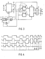
- the monostable multivibrators 35 and 36 supply signals T 1 and T 2 , respectively, which are combined with the trigger signal T s in the logic circuit 48 to form the signals T h and T l in conformity with the relationships:
- the two multivibrators 35 and 36 and the circuit 48 will be described with reference to Fig. 4, which shows the signals T s , T 1 , T 2 , T l and T h .
- the signal T s is the limited tracking signal whose period is inversely proportional to the jumping speed.
- the multivibrator 35 supplies pulses of a fixed duration each starting at the trailing edges of the signal T s , whilst the multivibrator 36 supplies the same pulses starting at the leading edges.
- the resulting signal T then has a relative pulse width which is proportional to the positive difference between the pulse width of the signal T s and the pulse width of the signals T 1 and T 2 , determined by the time constant of the multivibrators, or a relative pulse width which is a measure of the extent to which the jumping speed deviates in a negative sense from a nominal speed defined by the time constant of the multivibrators.
- the relative pulse width of the signal T h is a measure of the extent to which the jumping speed deviates from said nominal speed in a positive sense.
- the signals T h and T are applied to a commutator 38, which exchanges these signals depending on the jump direction indicated by the signal on output 29.
- Said signals Th and T, control switches 33 and 40 which supply a positive or a negative supply voltage to output 29 or which makes the output floating, so that the motor 7 accelerates, decelerates and freewheels, respectively.
- Fig. 5a represents the jumping speed v as a function of time.
- Figs. 5b, 5c and 5d represent the signals on outputs 28, 30 and 31 of the control-signal generator 24,
- Fig. 5e shows the limited radial tracking-error signal,
- Fig. 5f shows a control signal for the motor 7 on output 29.
- the comparator 13 supplies the starting command to input 26. Via output 28 (signal shown in Fig. 5b) switch 23 is changed over. Via output 31 (signal shown in Fig. 5d) the time constant of the multivibrators 35 and 36 is set to a small value corresponding to a high nominal jumping speed. Until an instant t 1 the signal on output 30 (signal shown in Fig. 5c) remains low, so that the two multivibrators are inoperative, the signals T, and T 2 are low, the signal T h is high and the signal T, is low. During the period to to t 1 the motor 7 is then accelerated continuously (see Fig. 5a).
- the two multivibrators are started and the signals T h and T, corresponding to the diagram shown in Fig. 4 are generated.
- the jump is then performed with a substantially constant speed.
- the signal on output 31 (Fig. 5d) switches the time constant of the multivibrators to a high value corresponding to a low nominal speed.
- the circuit then also generates a train of braking pulses T, until at instant t 3 this lower nominal speed is reached.
- the jump continues with said constant lower speed until at the instant t 4 the number of tracks to be jumped minus half a track is reached.
- the signal on output 28 resets the switch 23 (Fig. 1) and locking- in to the desired track is effected via the tracking mechanism.
- a signal on an input 42 is combined with the output signal of the exclusive-or-gate 33 by means of the signal on output 31 via an or-gate 41 and an exclusive-or-gate 37.
- a signal which is 90° phase-shifted relative to the limited radial error signal is applied to this input 42.
- the signal on output 31 is low, which is the case at the lower nominal speed, this signal is added to the limited radial tracking-error signal in the exclusive-or-gate 37, yielding a signal of twice the repetition frequency.
- the device shown in Fig. 3 may be designed so that for a jump of less than a predetermined number of tracks (for example 25) the signal on output 31 (Fig. 5d) is kept low throughout jumping period, so that the mirror is controlled directly towards the lower of the two speeds.
- the apparatus described herein may be formed partly, in particularly parts 9, 12, 13 and 24, by a microprocessor.
Abstract
Description
- The invention relates to an apparatus for reading a disc-shaped record carrier in which video signals are recorded in substantially spiral tracks in such a way that corresponding picture elements of consecutive video pictures are situated at substantially the same circumferential position on said record carrier, an address code being contained in at least one of the two fields of the video signal representing a video picture at a predetermined position in the field blanking interval after the field-synchronizing pulse, which apparatus comprises:
- an optical system for aiming a light beam at the record carrier, said light beam being modulated by the record carrier, and for converting said modulated light beam into an electric signal,
- a converter for converting said electric signal into a radial tracking-error signal which corresponds to the radial position of the landing spot of the light beam relative to a desired track,
- positioning means for controlling the position of the landing spot of the light beam as a function of the radial tracking-error signal,
- a jump-signal generator for generating a control signal for causing the landing spot of the light beam to be shifted over a predetermined distance in response to a jump signal, and
- means for applying said control signal to the positioning means during said jump.
- Such apparatus is inter alia the video-disc player which is commercially available from N. V. Philips' Gloeilampenfabrieken under the designation "Laservision" and which is described inter alia in the magazine "Philips Technical Review", Vol. 33, 1973, No. 7, pages 177-193 and United States Patent Specification No. RE 29,963. In this known apparatus a jump of one or a few tracks is made in order to obtain still picture, slow motion etc. In said apparatus a predetermined signal is applied via the field synchronizing pulse during the field-blanking interval in order to obtain a jump of the positioning means over a specific distance.
- For some use, such as in interactive video disc players which cooperate with a game computer, it is desirable to have the possibility of changing the scene being reproduced, for which purpose the landing spot of the laser beam must be changed very rapidly over a large number of tracks in a radial direction by the positioning means, for example a pivotal mirror, though it is also possible to use other actuators such as linearly moving actuators. In particular because in such a case a plurality of scenes may have been recorded in parallel and may change from track to track, it is essential that such a jump in a radial direction ends at the desired track, because otherwise a scene other than the desired scene is reached. In order to be able to ascertain immediately whether a jump is correct, it is therefore necessary that the address code can be read after the jump and that consequently the jump is always terminated before said address code is read.
- It is the object of the invention to provide an apparatus of the type specified in the opening paragraph by means of which said jumps can be effected in such a manner that they always terminate before said address code and in such a manner that the disturbance of the picture is minimal.
- To this end the invention is characterized by
- means for generating a first signal which is a continuous measure of the duration of the period of time up to a reference point in the next field blanking interval, which point precedes the address code in said field blanking interval,
- means for generating a second signal under command of the jump signal, which second signal is a measure of the anticipated duration of the jump to be performed in response to said command, and
- means for continuously comparing said first and said second signal and, in relation to the instant at which the two durations correspond, generating a start signal for the jump-signal generator at least if said instant appears prior to the field-synchronizing pulse preceding said address code.
- The steps in accordance with the invention ensure that the jumps always terminate prior to the read-out of the address code. Maximum jumps longer than the field blanking interval are permissible without the picture being disturbed significantly because the video signal of the preceding field is disturbed only and not to more than the necessary extent if the jumps are longer than the field blanking intervals, said disturbance then appearing in the lower lines of the picture in only one field during a change of scene.
- With respect to the means for generating the first signal the apparatus may further be characterized in that said means for generating the first signal comprise counting means which are started each time that an address code appears.
- The invention will now be described in more detail, by way of example, with reference to the drawings in which:
- Fig. 1 shows an apparatus in accordance with the invention,
- Fig. 2 shows some diagrams to explain the operation of the apparatus shown in Fig. 1,
- Fig. 3 shows a version of the jump-
signal generator 14 in the apparatus shown in Fig. 1, - Fig. 4 shows some diagrams to explain the operation of a part of the generator shown in Fig. 3, and
- Fig. 5 shows some diagrams representing the various signals which appear when a jump is performed by means of the jump-signal generator shown in Fig. 3.
- Fig. 1 shows an apparatus in accordance with the invention for reading a rotating optically
readable record carrier 1. For the purpose of reading a light beam emitted by a laser 2 is projected on the record carrier via apivotal mirror 3 and an objective 4, the beam which is reflected by this record carrier being projected on a detector 6 via asemi-transparent mirror 5. Specifically in the case of VLP the laser beam comprises one main beam two sub-beams and the detector comprises 3 sub-detectors, so that by means of one tracking-error signal generator 15 a signal can be obtained which is a measure of the position of the landing spot of the laser beam relative to information tracks on therecord carrier 1. By means of this signal the position of said spot is controlled in that the entireoptical system 16 can be moved in a radial direction by means of amechanism 22, shown symbolically, and in that themirror 3 can be tilted by means of amotor 7, enabling the landing spot of the beam to be moved over a limited number of tracks in a rapid and accurate manner. This is described comprehensively in inter alia the magazine Philips Technical Review, Vol. 33,1973, No. 7, pages 186, 189, United States Patent Specification 4,037,252, and German Patent Application No. 31.21.013, which has been laid open to public inspection, which publications are herewith incorporated by reference. - Fig. 2a schematically represents the structure of a video signal which has been read from the
record carrier 1. For each picture said signal comprises two field synchronizing pulses S1 and S2, which after 16 picture lines are each followed by two picture lines (17 and 18) containing an address code (in principle it is also possible to use only one address code per picture). The visible part of the picture extends from line 21 up to line 262.5 (NTSC). - For some uses such as interactive players which cooperate with a game computer, it is desirable to be able to change the scene being reproduced without disturbing the field sequence, for which purpose the landing spot of the laser beam must be shifted radially over a plurality of tracks by means of the
pivotal mirror 3. In particular since for such a use a plurality of scenes may have been recorded in parallel and may change from track to track, it is essential that such a radial jump ends on the desired track because otherwise a scene other than the desired scene may be reached. In order to be able to ascertain directly whether such a jump is correct, it is therefore necessary that the address code contained in lines 17 and 18 is read after the jump and that the jump therefore always terminates before line 17 of the next field. - Since a picture disturbance of a few lines in the lower part of the picture during one field just before a change of scene is not very annoying, the maximum number of tracks to be jumped can be selected in such a way that the maximum jump starts a specific number of lines before the last line of the visible video picture and terminates just before line 17 of the next field. In order to minimize the picture disturbance the instant at which the jump begins is always selected so that a minimal number of lines of the visible video picture is disturbed, jumping being effected in such a way that, if possible, a jump is made before the next address code after receipt of a jump command. This is possible by continuously measuring the time still available until the next address code appears.
- In the embodiment shown in Fig. 1 this is achieved as follows. A detection circuit 8 derives a signal, for example shown in Fig. 2b, which is synchronous with the address code, or with line 17, from the video signal recovered by means of the detector 6. This signal each time starts a
counter 9, which counts a counting signal supplied by a clock-signal generator 10. Thiscounter 9 then supplies a signal which is a continuous measure of the time which has elapsed after the read-out of the last address code and consequently of the time available until the appearance of the next address code. The jump command is applied to aninput 11 as a signal which is a measure of the number of tracks to be jumped, for example in the form of a digital signal. In acircuit 12 this signal is converted into a signal which is a measure of the time required for this jump. By means of acomparator 13 the time required is compared with the running time and a signal is generated when the time available until the appearance of the next address code corresponds to the time required. Fig. 2c shows an example of such a signal. By means of this signal a jump-signal generator 14 is started. This jump-signal generator 14 controls a swittch 23 which interrupts the connection between the tracking-error signal generator 15 and themotor 7, so that themotor 7 is controlled by this jump-signal generator 14 until a jump of the desired number of tracks is obtained. For this purpose the jump-signal generator 14 receives a signal indicating the number of tracks to be jumped frominput 11 and a signal which indicates the passage of the tracks and which is supplied by a tracking-signal generator 15, of which examples are described in the publications referred to. - In its simplest form the
circuit 12 for generating a signal which is a measure of the time required for the jump can establish a linear relationship between the time required and the number of tracks to be jumped. If a more accurate relationship is required, thecircuit 12 may perform an algorithm which defines said relationship or may contain a conversion table based on this relationship. For example, allowance can be made for the non-linearity of this relationship as a result of starting and braking the movement of thepivotal mirror 3. It is also possible to select a fixed jumping instant by starting those jumps which require a time shorter than a specific time, for example all jumps requiring time which is shorter than the time between the last visible picture line of the relevant field and the next address code, at the end of said last visible picture line, an extreme jumping instant being defined only for longer jumps. - The tracking-
signal generator 15, in known manner, supplies a control signal to the drive motor via theswitch 23, in order to keep the laser beam aimed at the track to be followed when no jump is performed. - Fig. 3 shows a version of the jump-
signal generator 14. It comprises a control-signal generator 24 on whose input 25 a signal appears which viainput 11 indicates the number of tracks to be jumped and on whose input 26 a starting signal from a comparator 13 (Fig. 1) appears. On an output 28 a signal appears which sets theswitch 23 to the position shown in Fig. 1 for the duration of the jump. On an output 29 a signal appears which indicates the direction of the jump. The radial tracking-error signal generator 15 is applied to aninput 27. By means of alimiter 32 the signal is converted into a squarewave signal which when the laser beam moves over the tracks in the radial direction exhibits a period corresponding to the time interval between the consecutive track passages and has edges appearing in the centre of the tracks and midway between the tracks. By means of an exclusive-OR-circuit 33 the signal is logically combined with the direction signal onoutput 29, so that a signal is obtained which is independent of the direction of the jump. This signal is applied to input 34 of the control-signal generator 24 which counts the number of tracks passed by means of this signal. Onoutput 30 the control-signal generator 24 supplies a logic signal from an instant which appears a fixed time, for example 350 psecs after the start of the jump until the end of the jump, and onoutput 31 the control-signal generator supplies a logic signal from the beginning of the jump until an instant at which the number of tracks to be jumped (n) minus a predetermined number of tracks (x) has been passed. - The jump-signal generator further comprises a first
monostable multivibrator circuit 35 which receives a trigger signal Ts on an inverted trigger input T, and a secondmonostable multivibrator circuit 36 which receives the trigger signal Ts on the trigger input T. Via an exclusive-or-gate 37 this trigger signal Ts is supplied by the output of the exclusive-or-gate 33, thegate 37 transferring this signal when a logic "1" appears on the other input of thisgate 37. Themonostable multivibrator circuits output 30 of the control-signal generator 24 and their time constant, i.e. the length of the pulse supplied, is changed over by the signal on theoutput 31 of the control circuit. Themonostable multivibrators logic circuit 48 to form the signals Th and Tl in conformity with the relationships:

- The operation of the two
multivibrators circuit 48 will be described with reference to Fig. 4, which shows the signals Ts, T1, T2, Tl and Th. When ignoring a possible inversion depending on the direction of the jump, the signal Ts is the limited tracking signal whose period is inversely proportional to the jumping speed. As it is triggered on its inverting trigger input, themultivibrator 35 supplies pulses of a fixed duration each starting at the trailing edges of the signal Ts, whilst themultivibrator 36 supplies the same pulses starting at the leading edges. The resulting signal T, then has a relative pulse width which is proportional to the positive difference between the pulse width of the signal Ts and the pulse width of the signals T1 and T2, determined by the time constant of the multivibrators, or a relative pulse width which is a measure of the extent to which the jumping speed deviates in a negative sense from a nominal speed defined by the time constant of the multivibrators. Similarly, the relative pulse width of the signal Th is a measure of the extent to which the jumping speed deviates from said nominal speed in a positive sense. - The signals Th and T are applied to a
commutator 38, which exchanges these signals depending on the jump direction indicated by the signal onoutput 29. Said signals Th and T, control switches 33 and 40 which supply a positive or a negative supply voltage tooutput 29 or which makes the output floating, so that themotor 7 accelerates, decelerates and freewheels, respectively. - The operation of the entire jump-
signal generator 14 is explained with reference to Fig. 5, in which Fig. 5a represents the jumping speed v as a function of time. Figs. 5b, 5c and 5d represent the signals onoutputs signal generator 24, Fig. 5e shows the limited radial tracking-error signal, and Fig. 5f shows a control signal for themotor 7 onoutput 29. - At an instant to the
comparator 13 supplies the starting command to input 26. Via output 28 (signal shown in Fig. 5b) switch 23 is changed over. Via output 31 (signal shown in Fig. 5d) the time constant of themultivibrators motor 7 is then accelerated continuously (see Fig. 5a). At the instant t1 the two multivibrators are started and the signals Th and T, corresponding to the diagram shown in Fig. 4 are generated. The jump is then performed with a substantially constant speed. After the passage of the number of tracks to be jumped (n) minus a predetermined number of tracks (x) at the instant t2 the signal on output 31 (Fig. 5d) switches the time constant of the multivibrators to a high value corresponding to a low nominal speed. The circuit then also generates a train of braking pulses T, until at instant t3 this lower nominal speed is reached. Subsequently, the jump continues with said constant lower speed until at the instant t4 the number of tracks to be jumped minus half a track is reached. At this instant the signal onoutput 28 resets the switch 23 (Fig. 1) and locking- in to the desired track is effected via the tracking mechanism. - Since at the lower nominal speed the repetition frequency of the limited tracking-error signal decreases substantially a signal on an
input 42 is combined with the output signal of the exclusive-or-gate 33 by means of the signal onoutput 31 via an or-gate 41 and an exclusive-or-gate 37. A signal which is 90° phase-shifted relative to the limited radial error signal is applied to thisinput 42. When the signal onoutput 31 is low, which is the case at the lower nominal speed, this signal is added to the limited radial tracking-error signal in the exclusive-or-gate 37, yielding a signal of twice the repetition frequency. - The device shown in Fig. 3 may be designed so that for a jump of less than a predetermined number of tracks (for example 25) the signal on output 31 (Fig. 5d) is kept low throughout jumping period, so that the mirror is controlled directly towards the lower of the two speeds.
- It is to be noted that the apparatus described herein may be formed partly, in particularly
parts
Claims (2)
Priority Applications (1)
| Application Number | Priority Date | Filing Date | Title |
|---|---|---|---|
| AT84201240T ATE40486T1 (en) | 1983-09-01 | 1984-08-28 | DEVICE FOR READING A DISC-FORM RECORDING CARRIER. |
Applications Claiming Priority (2)
| Application Number | Priority Date | Filing Date | Title |
|---|---|---|---|
| NL8303046A NL8303046A (en) | 1983-09-01 | 1983-09-01 | DEVICE FOR READING A DISC REGISTRATION CARRIER. |
| NL8303046 | 1983-09-01 |
Publications (2)
| Publication Number | Publication Date |
|---|---|
| EP0138245A1 EP0138245A1 (en) | 1985-04-24 |
| EP0138245B1 true EP0138245B1 (en) | 1989-01-25 |
Family
ID=19842334
Family Applications (1)
| Application Number | Title | Priority Date | Filing Date |
|---|---|---|---|
| EP84201240A Expired EP0138245B1 (en) | 1983-09-01 | 1984-08-28 | Apparatus for reading a disc-shaped record carrier |
Country Status (12)
| Country | Link |
|---|---|
| US (1) | US4567534A (en) |
| EP (1) | EP0138245B1 (en) |
| JP (1) | JPH0783461B2 (en) |
| KR (1) | KR920005261B1 (en) |
| AT (1) | ATE40486T1 (en) |
| AU (1) | AU572885B2 (en) |
| CA (1) | CA1235500A (en) |
| DE (1) | DE3476480D1 (en) |
| ES (1) | ES8505486A1 (en) |
| HK (1) | HK82991A (en) |
| NL (1) | NL8303046A (en) |
| SG (1) | SG51190G (en) |
Families Citing this family (13)
| Publication number | Priority date | Publication date | Assignee | Title |
|---|---|---|---|---|
| JPS61104337A (en) * | 1984-10-24 | 1986-05-22 | Hitachi Ltd | Optical information recording and reproducing device |
| JPS6273430A (en) * | 1985-09-26 | 1987-04-04 | Canon Inc | Optical information recording and reproducing device |
| US5166805A (en) * | 1985-06-18 | 1992-11-24 | Pioneer Electronic Corporation | Disk player with a blanking during fast scanning |
| US4819219A (en) * | 1986-03-25 | 1989-04-04 | Kabushiki Kaisha Toshiba | Track jump control system for optical disk apparatus |
| US4862291A (en) * | 1986-11-14 | 1989-08-29 | Pioneer Electronic Corporation | Scanning system in information reproducing apparatus |
| DE3887126T2 (en) * | 1987-08-29 | 1994-04-28 | Fujitsu Ltd | METHODS TO ACCESS AN OPTICAL RECORDING TRACK. |
| US4897827A (en) * | 1987-12-12 | 1990-01-30 | U.S. Philips Corporation | Video disc player with rapid track access means |
| NL9002111A (en) * | 1990-09-19 | 1992-04-16 | Koninkl Philips Electronics Nv | METHOD FOR RECORDING IMAGE INFORMATION, AND A REGISTRATION CARRIER, AND AN IMAGE SEARCH AND DISPLAY DEVICE FOR READING THE REGISTRATION CARRIER. |
| CZ289474B6 (en) * | 1990-09-19 | 2002-01-16 | Koninklijke Philips Electronics N. V. | Picture retrieval system comprising a record carrier and a read device |
| US5473584A (en) | 1992-01-29 | 1995-12-05 | Matsushita Electric Industrial Co., Ltd. | Recording and reproducing apparatus |
| USRE40957E1 (en) | 1992-01-29 | 2009-11-10 | Panasonic Corporation | Medium, apparatus, and method related to encryption resultant information |
| EP1050879A3 (en) * | 1993-07-27 | 2006-10-18 | Matsushita Electric Industrial Co., Ltd. | Recording and reproducing apparatus with means for encryption of information |
| JP3826856B2 (en) * | 2002-08-05 | 2006-09-27 | ソニー株式会社 | REPRODUCTION CONTROL DEVICE, REPRODUCTION CONTROL METHOD, AND REPRODUCTION CONTROL PROGRAM |
Family Cites Families (13)
| Publication number | Priority date | Publication date | Assignee | Title |
|---|---|---|---|---|
| FR2349191A1 (en) * | 1976-04-23 | 1977-11-18 | Thomson Brandt | OPTICAL INFORMATION DISC READER INCLUDING AN AUTOMATIC INFORMATION ACCESS DEVICE |
| FR2396379A1 (en) * | 1977-07-01 | 1979-01-26 | Thomson Brandt | OPTICAL INFORMATION DISC READER EQUIPPED WITH AN AUTOMATIC INFORMATION ACCESS DEVICE |
| JPS576443A (en) * | 1980-06-13 | 1982-01-13 | Matsushita Electric Ind Co Ltd | Recorder and reproducer |
| JPS5753880A (en) * | 1980-09-12 | 1982-03-31 | Victor Co Of Japan Ltd | Detector of periodic signal |
| JPS5765075A (en) * | 1980-10-08 | 1982-04-20 | Trio Kenwood Corp | High speed reproduction method of video disc |
| JPS57104386A (en) * | 1980-12-19 | 1982-06-29 | Trio Kenwood Corp | Video disc playback device |
| JPS57120272A (en) * | 1981-01-14 | 1982-07-27 | Victor Co Of Japan Ltd | Reproducing device for discoid information recording medium |
| JPS57150173A (en) * | 1981-03-12 | 1982-09-16 | Victor Co Of Japan Ltd | Reproducer for disc shape information recording medium |
| JPS5862868A (en) * | 1981-10-09 | 1983-04-14 | Pioneer Video Corp | High speed address information searching system of information reproducing device |
| JPS5896474A (en) * | 1981-12-04 | 1983-06-08 | Matsushita Electric Ind Co Ltd | Video disc reproducer |
| JPS58171730A (en) * | 1982-03-31 | 1983-10-08 | Sony Corp | Disc reproducing device |
| US4536863A (en) * | 1982-04-15 | 1985-08-20 | Discovision Associates | Method and apparatus for recovering information from a videodisc |
| JPS58196047U (en) * | 1982-06-18 | 1983-12-27 | 日立精機株式会社 | reduction gear |
-
1983
- 1983-09-01 NL NL8303046A patent/NL8303046A/en not_active Application Discontinuation
- 1983-12-07 US US06/559,064 patent/US4567534A/en not_active Expired - Fee Related
-
1984
- 1984-08-28 DE DE8484201240T patent/DE3476480D1/en not_active Expired
- 1984-08-28 AT AT84201240T patent/ATE40486T1/en active
- 1984-08-28 EP EP84201240A patent/EP0138245B1/en not_active Expired
- 1984-08-29 ES ES535485A patent/ES8505486A1/en not_active Expired
- 1984-08-30 CA CA000462123A patent/CA1235500A/en not_active Expired
- 1984-08-31 AU AU32585/84A patent/AU572885B2/en not_active Ceased
- 1984-08-31 JP JP59182520A patent/JPH0783461B2/en not_active Expired - Lifetime
- 1984-09-01 KR KR1019840005382A patent/KR920005261B1/en not_active IP Right Cessation
-
1990
- 1990-07-04 SG SG511/90A patent/SG51190G/en unknown
-
1991
- 1991-10-24 HK HK829/91A patent/HK82991A/en unknown
Also Published As
| Publication number | Publication date |
|---|---|
| ES535485A0 (en) | 1985-05-16 |
| KR920005261B1 (en) | 1992-06-29 |
| EP0138245A1 (en) | 1985-04-24 |
| CA1235500A (en) | 1988-04-19 |
| US4567534A (en) | 1986-01-28 |
| AU3258584A (en) | 1985-03-07 |
| NL8303046A (en) | 1985-04-01 |
| JPH0783461B2 (en) | 1995-09-06 |
| JPS6090480A (en) | 1985-05-21 |
| SG51190G (en) | 1990-08-31 |
| KR850002535A (en) | 1985-05-13 |
| HK82991A (en) | 1991-11-01 |
| ES8505486A1 (en) | 1985-05-16 |
| DE3476480D1 (en) | 1989-03-02 |
| ATE40486T1 (en) | 1989-02-15 |
| AU572885B2 (en) | 1988-05-19 |
Similar Documents
| Publication | Publication Date | Title |
|---|---|---|
| US4338682A (en) | Tracking servo system of video disc player | |
| EP0138245B1 (en) | Apparatus for reading a disc-shaped record carrier | |
| JPH0519356B2 (en) | ||
| US4397009A (en) | Device for locating a desired information track | |
| US4539664A (en) | Control system for optical information signal reproduction device | |
| EP0236944B1 (en) | Method and system for playing back information recorded on a recording disk | |
| KR920000422B1 (en) | Track-jumping apparatus for optical disk | |
| JP2781683B2 (en) | Playback device for recorded information | |
| US5097365A (en) | Automatic tracking apparatus for magnetic disk playback head | |
| US5105406A (en) | Track-jumping servo apparatus for disc-shaped optical record medium | |
| EP0152141B1 (en) | System for playing back a programme recorded on a disc-shaped record carrier | |
| US4800445A (en) | Videodisk player | |
| JP2836756B2 (en) | Track jump control device for optical information recording / reproducing device | |
| KR910006076B1 (en) | Disk player | |
| JPS6047274A (en) | High speed search method of information signal | |
| JPH0197076A (en) | Frame index magnetic recording and reproducing device | |
| JPS6214910B2 (en) | ||
| JP2725278B2 (en) | Video disc player | |
| KR900002880Y1 (en) | Track switch controlling circuit of video disk player in time of scanning | |
| KR890004244B1 (en) | Slow regeneration method | |
| JPS60160274A (en) | Slow reproducing method | |
| JP3028871B2 (en) | Optical disk recording and playback device | |
| JP2725277B2 (en) | Video disc player | |
| KR100520945B1 (en) | Track movement method of optical pickup device | |
| JP2639601B2 (en) | Speed detection device in optical disk device |
Legal Events
| Date | Code | Title | Description |
|---|---|---|---|
| PUAI | Public reference made under article 153(3) epc to a published international application that has entered the european phase |
Free format text: ORIGINAL CODE: 0009012 |
|
| AK | Designated contracting states |
Designated state(s): AT BE DE FR GB IT SE |
|
| 17P | Request for examination filed |
Effective date: 19851016 |
|
| 17Q | First examination report despatched |
Effective date: 19861218 |
|
| D17Q | First examination report despatched (deleted) | ||
| GRAA | (expected) grant |
Free format text: ORIGINAL CODE: 0009210 |
|
| AK | Designated contracting states |
Kind code of ref document: B1 Designated state(s): AT BE DE FR GB IT SE |
|
| REF | Corresponds to: |
Ref document number: 40486 Country of ref document: AT Date of ref document: 19890215 Kind code of ref document: T |
|
| REF | Corresponds to: |
Ref document number: 3476480 Country of ref document: DE Date of ref document: 19890302 |
|
| ITF | It: translation for a ep patent filed |
Owner name: ING. C. GREGORJ S.P.A. |
|
| ET | Fr: translation filed | ||
| PLBE | No opposition filed within time limit |
Free format text: ORIGINAL CODE: 0009261 |
|
| STAA | Information on the status of an ep patent application or granted ep patent |
Free format text: STATUS: NO OPPOSITION FILED WITHIN TIME LIMIT |
|
| 26N | No opposition filed | ||
| ITTA | It: last paid annual fee | ||
| PGFP | Annual fee paid to national office [announced via postgrant information from national office to epo] |
Ref country code: GB Payment date: 19940728 Year of fee payment: 11 |
|
| PGFP | Annual fee paid to national office [announced via postgrant information from national office to epo] |
Ref country code: BE Payment date: 19940808 Year of fee payment: 11 |
|
| PGFP | Annual fee paid to national office [announced via postgrant information from national office to epo] |
Ref country code: AT Payment date: 19940824 Year of fee payment: 11 |
|
| PGFP | Annual fee paid to national office [announced via postgrant information from national office to epo] |
Ref country code: FR Payment date: 19940825 Year of fee payment: 11 |
|
| PGFP | Annual fee paid to national office [announced via postgrant information from national office to epo] |
Ref country code: SE Payment date: 19940826 Year of fee payment: 11 |
|
| PGFP | Annual fee paid to national office [announced via postgrant information from national office to epo] |
Ref country code: DE Payment date: 19941026 Year of fee payment: 11 |
|
| EAL | Se: european patent in force in sweden |
Ref document number: 84201240.3 |
|
| ITPR | It: changes in ownership of a european patent |
Owner name: CAMBIO RAGIONE SOCIALE;PHILIPS ELECTRONICS N.V. |
|
| PG25 | Lapsed in a contracting state [announced via postgrant information from national office to epo] |
Ref country code: GB Effective date: 19950828 Ref country code: AT Effective date: 19950828 |
|
| PG25 | Lapsed in a contracting state [announced via postgrant information from national office to epo] |
Ref country code: SE Effective date: 19950829 |
|
| PG25 | Lapsed in a contracting state [announced via postgrant information from national office to epo] |
Ref country code: BE Effective date: 19950831 |
|
| BERE | Be: lapsed |
Owner name: PHILIPS ELECTRONICS N.V. Effective date: 19950831 |
|
| GBPC | Gb: european patent ceased through non-payment of renewal fee |
Effective date: 19950828 |
|
| PG25 | Lapsed in a contracting state [announced via postgrant information from national office to epo] |
Ref country code: FR Effective date: 19960430 |
|
| PG25 | Lapsed in a contracting state [announced via postgrant information from national office to epo] |
Ref country code: DE Effective date: 19960501 |
|
| EUG | Se: european patent has lapsed |
Ref document number: 84201240.3 |
|
| REG | Reference to a national code |
Ref country code: FR Ref legal event code: ST |