EP0138687A1 - Surgical fastener exhibiting improved hemostasis - Google Patents
Surgical fastener exhibiting improved hemostasis Download PDFInfo
- Publication number
- EP0138687A1 EP0138687A1 EP84401936A EP84401936A EP0138687A1 EP 0138687 A1 EP0138687 A1 EP 0138687A1 EP 84401936 A EP84401936 A EP 84401936A EP 84401936 A EP84401936 A EP 84401936A EP 0138687 A1 EP0138687 A1 EP 0138687A1
- Authority
- EP
- European Patent Office
- Prior art keywords
- fastener
- base
- fasteners
- retainer
- members
- Prior art date
- Legal status (The legal status is an assumption and is not a legal conclusion. Google has not performed a legal analysis and makes no representation as to the accuracy of the status listed.)
- Granted
Links
Images
Classifications
-
- A—HUMAN NECESSITIES
- A61—MEDICAL OR VETERINARY SCIENCE; HYGIENE
- A61B—DIAGNOSIS; SURGERY; IDENTIFICATION
- A61B17/00—Surgical instruments, devices or methods, e.g. tourniquets
- A61B17/064—Surgical staples, i.e. penetrating the tissue
- A61B17/0643—Surgical staples, i.e. penetrating the tissue with separate closing member, e.g. for interlocking with staple
-
- A—HUMAN NECESSITIES
- A61—MEDICAL OR VETERINARY SCIENCE; HYGIENE
- A61B—DIAGNOSIS; SURGERY; IDENTIFICATION
- A61B17/00—Surgical instruments, devices or methods, e.g. tourniquets
- A61B17/068—Surgical staplers, e.g. containing multiple staples or clamps
- A61B17/072—Surgical staplers, e.g. containing multiple staples or clamps for applying a row of staples in a single action, e.g. the staples being applied simultaneously
Definitions
- This invention relates to surgical fasteners (e.g., staples), and more particularly to a fastener comprising a fastener member and a retainer member and exhibiting improved hemostasis.
- surgical fasteners e.g., staples
- Surgical fastening devices allow a surgeon to fasten body tissue by applying surgical fasteners.
- the fasteners may be applied singly in succession or a number may be applied simultaneously.
- Surgical fasteners are often made of metals such as tantalum and stainless steel, which are inert.
- Fasteners of magnesium, which fasteners are gradually absorbed by the body, are also known.
- Non-metallic fasteners are also known and may be preferable to metal fasteners in some procedures.
- non-metallic fasteners can be made X-ray transparent so that they do not scatter X-rays and therefore do not degrade the quality of radiographs as may happen when metal fasteners are used.
- resinous materials are usually too resilient (i.e., elastic) to hold deformed shapes (assuming plastic flow does not occur).
- resinous materials means non-metallic materials, such as natural or synthetic polymers and resins, including protein-based materials, which are relatively flexible and elastic, and which may or may not be absorbable in the body.
- the greater elasticity of resinous materials generally makes it impossible to directly substitute such materials for the metal in conventional surgical fasteners.
- resinous surgical fasteners may be made of two parts: a fastener member and a retainer member.
- the legs or prongs of the fastener member are driven through one side of the tissue to be fastened and the retainer member interlocks with the prongs of the fastener member on the other side of the tissue to hold the entire fastener structure in place.
- One such fastener structure and apparatus for applying it are disclosed in Green U.S. patent 4,402,445, issued September 6, 1983, which is hereby incorporated by reference in its entirety.
- a frequent goal in fastening tissue is achieving hemostasis along the fastener line. Hemostasis is achieved by exerting pressure on the tissue from both sides. If metal staples are used, that pressure (hereinafter referred to as “hemostatic pressure") is exerted by and between the base of the staple on one side of the tissue and the crimped legs on the other side of the tissue. In typical crimped metal staples no part of the staple extends beyond the ends of the base. Therefore, a second staple can be applied very close to the first staple, so that the bases of the two staples are in a line. In that case the gap between staples can be quite small so that hemostatic pressure is applied uniformly along the entire staple line.
- One way to make up for the above-mentioned gaps in a line of resinous fasteners is to apply the fasteners in two parallel rows, with a linear offset between the rows so that the gaps in one row are opposite the bases of the fastener members of the other row.
- this doubles the number of fasteners that are required and increases the area of tissue affected by the fasteners.
- a surgical fastener that exerts hemostasic pressure along its entire length and cooperates with the applying apparatus to minimize splaying of the prongs.
- the surgical fastener comprises a fastener member and a retainer member and is applied to tissue in a row in which the lengths of the fasteners are in a line and in which adjacent fasteners are nearly touching each other.
- the fastener member comprises (1) a base and (2) a pair of substantially parallel prongs extending substantially perpendicularly from the base in substantially the same direction, each prong being spaced inward from its respective end of the base.
- the base is the same length as the retainer member.
- the prongs are substantially equidistant from the transverse centerline of the base.
- a fastener-applying apparatus for use with the fastener of this invention contains a number of pusher members corresponding to the number of fasteners to be fired.
- a plurality of retainer members and a corresponding number of fastener members are positioned within the apparatus.
- the pusher members force the fastener members through tissue into engagement with the retainer members by pushing the bases of the fastener members.
- the length of each pusher member parallel to the longitudinal axis of the associated fastener member base is substantially equal to the length of the associated fastener member base, and each pusher member exerts pressure along substantially the entire length of each fastener member base.
- the present invention finds its greatest use with surgical fasteners of resinous materials, although the invention may be used with fasteners of other materials that have separate fastener and retainer members.
- a preferred resinous material, which is absorbable in the body, is disclosed in copending, commonly-assigned Kaplan et al. U.S. patent application Serial No. 436,056, filed October 22, 1982, hereby incorporated by reference in its entirety.
- the present invention provides a surgical fastener that exerts hemostatic pressure along its entire length and cooperates with fastener-applying apparatus to reduce splaying of the prongs of the fastener while the fastener is being applied to tissue.
- Surgical fastener 100 in FIG. 1 includes retainer member 104 and fastener member 101, which has two prongs 102 depending from base 105. Prongs 102 are driven through tissue to engage apertures 103, whose sidewalls are indicated by dashed lines 103a, in retainer member 104. Both members may be made from a resinous material which may or may not be absorbable in the body.
- each area 204 in one row is opposite an area 203 in the other row. Seepage of fluids through any gaps 205 in one row is arrested at corresponding areas 203 in the other row.
- Fastener 400 reduces or eliminates the need for a second row of fasteners to provide total hemostasis.
- Fastener 400 according to the present invention is shown in FIG. 4.
- Preferred fastener member 401 can be described as "pi-shaped" because of its resemblance to the Greek letter pi.
- Base 402 of fastener member 401 has extensions 403 and 404, which extend over areas 106 and 107.
- the retainer member and the base of the fastener member have substantially the same length; the sum of the lengths of extensions 403 and 404 is substantially equal to the sum of the lengths of areas 106 and 107 of FIG. 1.
- hemostatic pressure is exerted between extensions 403 and 404 and the corresponding portions of retainer member 104 extending beyond each aperture 103.
- FIG. 5 There full hemostatic pressure is exerted in area 501 as well as in areas 203. That is in contrast to the previously known fasteners, as seen in FIG. 2, where full hemostatic pressure may not be exerted in area 204.
- apertures 103 are usually located symmetrically along the length of retainer member 104 so that areas 106 and 107 are substantially equal in length. Extensions 403 and 404 of base 402 of fastener member 401 are therefore preferably also substantially equal in length, with prongs 102 substantially equidistant from transverse centerline 405 of base 402. However, these conditions are not necessary. It is only necessary that the lengths of the fastener and retainer members be substantially the same. That will provide the desired total hemostasis.
- the fasteners shown in FIG. 5 are shown with small gaps between adjacent fasteners. These gaps are shown because it is usually necessary to have some structure in the fastener-applying apparatus (not shown) to separate the channels through which the individual fastener members are guided towards the tissue.
- the tissue is generally compressed by the fastener-applying apparatus, thereby stretching the tissue.
- the fastener-applying apparatus is removed from the tissue, the tissue tends to resume its former shape. That brings the fasteners in the tissue closer together so that they are touching or nearly touching. It is desirable that adjacent fasteners in the tissue be nearly touching to provide full hemostasis, although there should preferably be some gap because it is also desirable that the fastener line be somewhat flexible on the tissue. (As used herein, "nearly touching" means touching or separated by a gap of between 0 mm and about 0.5 mm.)
- FIGS. 6 and 7 show the beneficial effect of extensions 403 and 404, in combination with fastener-applying pushers 701 (which are longer, parallel to the longitudinal axis of the fastener member base, than would otherwise be employed), in counteracting the tendency of prongs 102 to splay.
- FIG. 6 shows known fastener member 101 as it is about to pierce tissue 201 under the downward urging of pusher 601 in known fastener-applying apparatus (not otherwise shown).
- FIG. 7 shows fastener member 401 of this invention in the same position.
- pusher 701 is longer, in the direction parallel to the base of the fastener member, than pusher member 601 for fasteners of comparable size.
- pusher member 701 is preferably substantially equal in length in the above-identified direction to base 402 of fastener member 401, including extensions 403 and 404. As a consequence, pusher member 701 contacts fastener member 401 along the entire length of base 402. Pusher member 701 should not be measurably longer in that direction than base 402; otherwise, it would prevent adjacent fastener members from being applied to the tissue as close together as possible, which is necessary to provide hemostasis.
- the fastener-applying apparatus may be conventional, as exemplified by the above-identified Green patent, although the present invention may facilitate the provision of fastener-applying apparatus as shown in that patent without the metal guide pins.
- prongs 102 may tend to bend inward or outward. If prongs 102 try to bend inward, the base of either fastener member 101 or 401 bows upward as indicated at 602 in FIGS. 6 and 7-. Such upward bowing is prevented by the presence of pusher 601 or pusher 701 in either device.
Abstract
Description
- This invention relates to surgical fasteners (e.g., staples), and more particularly to a fastener comprising a fastener member and a retainer member and exhibiting improved hemostasis.
- Surgical fastening devices allow a surgeon to fasten body tissue by applying surgical fasteners. The fasteners may be applied singly in succession or a number may be applied simultaneously. Surgical fasteners are often made of metals such as tantalum and stainless steel, which are inert. Fasteners of magnesium, which fasteners are gradually absorbed by the body, are also known.
- Non-metallic fasteners are also known and may be preferable to metal fasteners in some procedures. For example, non-metallic fasteners can be made X-ray transparent so that they do not scatter X-rays and therefore do not degrade the quality of radiographs as may happen when metal fasteners are used.
- On the other hand, objects of non-metallic resinous materials are usually too resilient (i.e., elastic) to hold deformed shapes (assuming plastic flow does not occur). (As used herein, the term "resinous materials" means non-metallic materials, such as natural or synthetic polymers and resins, including protein-based materials, which are relatively flexible and elastic, and which may or may not be absorbable in the body.) The greater elasticity of resinous materials generally makes it impossible to directly substitute such materials for the metal in conventional surgical fasteners.
- To overcome this problem, resinous surgical fasteners may be made of two parts: a fastener member and a retainer member. The legs or prongs of the fastener member are driven through one side of the tissue to be fastened and the retainer member interlocks with the prongs of the fastener member on the other side of the tissue to hold the entire fastener structure in place. One such fastener structure and apparatus for applying it are disclosed in Green U.S. patent 4,402,445, issued September 6, 1983, which is hereby incorporated by reference in its entirety.
- A frequent goal in fastening tissue is achieving hemostasis along the fastener line. Hemostasis is achieved by exerting pressure on the tissue from both sides. If metal staples are used, that pressure (hereinafter referred to as "hemostatic pressure") is exerted by and between the base of the staple on one side of the tissue and the crimped legs on the other side of the tissue. In typical crimped metal staples no part of the staple extends beyond the ends of the base. Therefore, a second staple can be applied very close to the first staple, so that the bases of the two staples are in a line. In that case the gap between staples can be quite small so that hemostatic pressure is applied uniformly along the entire staple line.
- In contrast, when two-part resinous fasteners are used, hemostatic pressure is exerted by and between the retainer member and the base of the fastener member. In known two-part resinous fasteners the prongs of the fastener member extend from the ends of the base. The retainer member is typically longer than the distance between the prongs and therefore must extend beyond the fastener member base. Accordingly, the bases of adjacent fastener members lying in a line are separated by at least the sum of the distances by which adjacent retainer members extend beyond the associated fastener member bases. Thus, there are gaps between adjacent fastener members. Full hemostatic pressure is not exerted on the tissue in these gaps.
- One way to make up for the above-mentioned gaps in a line of resinous fasteners is to apply the fasteners in two parallel rows, with a linear offset between the rows so that the gaps in one row are opposite the bases of the fastener members of the other row. However, this doubles the number of fasteners that are required and increases the area of tissue affected by the fasteners.
- Another typical characteristic of resinous materials is that they are not as strong as metals. Surgical fasteners of resinous materials may therefore tend to deform during application to tissue. In particular, the fastener member prongs may tend to splay or spread apart as the prongs are forced through the tissue. One way to overcome this tendency is to provide a metal guide pin adjacent each prong to help the prong penetrate the tissue without deformation. After the fasteners have been applied, the guide pins are withdrawn from the tissue. This guide pin structure has the disadvantage that it increases the complexity and cost of the apparatus for applying the fasteners.
- In accordance with this invention, a surgical fastener that exerts hemostasic pressure along its entire length and cooperates with the applying apparatus to minimize splaying of the prongs is provided. The surgical fastener comprises a fastener member and a retainer member and is applied to tissue in a row in which the lengths of the fasteners are in a line and in which adjacent fasteners are nearly touching each other.
- The fastener member comprises (1) a base and (2) a pair of substantially parallel prongs extending substantially perpendicularly from the base in substantially the same direction, each prong being spaced inward from its respective end of the base. Preferably, the base is the same length as the retainer member. Also preferably, the prongs are substantially equidistant from the transverse centerline of the base.
- A fastener-applying apparatus for use with the fastener of this invention contains a number of pusher members corresponding to the number of fasteners to be fired. A plurality of retainer members and a corresponding number of fastener members are positioned within the apparatus. The pusher members force the fastener members through tissue into engagement with the retainer members by pushing the bases of the fastener members. The length of each pusher member parallel to the longitudinal axis of the associated fastener member base is substantially equal to the length of the associated fastener member base, and each pusher member exerts pressure along substantially the entire length of each fastener member base.
- The present invention finds its greatest use with surgical fasteners of resinous materials, although the invention may be used with fasteners of other materials that have separate fastener and retainer members. A preferred resinous material, which is absorbable in the body, is disclosed in copending, commonly-assigned Kaplan et al. U.S. patent application Serial No. 436,056, filed October 22, 1982, hereby incorporated by reference in its entirety.
- Thus, the present invention provides a surgical fastener that exerts hemostatic pressure along its entire length and cooperates with fastener-applying apparatus to reduce splaying of the prongs of the fastener while the fastener is being applied to tissue.
- The above and other advantages of the present invention will be more apparent after consideration of the accompanying drawings in which like parts are indicated by like reference characters throughout and in which:
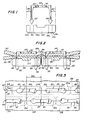
- FIG. 1 is an elevational view of a known surgical fastener;
- FIG. 2 is a cross-sectional view of tissue fastened with such fasteners;
- FIG. 3 is a fragmentary plan view of tissue fastened with such fasteners;
- FIG. 4 is an elevational view of a surgical fastener according to the present invention;
- FIG. 5 is a cross-sectional view of tissue fastened with such fasteners; and
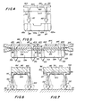
- FIGS. 6 and 7 are, respectively, fragmentary cross-sectional views of the fastener members of FIGS. 1 and 4 being applied to tissue by the pusher members of fastener-applying apparatus.
-
Surgical fastener 100 in FIG. 1 includesretainer member 104 andfastener member 101, which has twoprongs 102 depending frombase 105.Prongs 102 are driven through tissue to engageapertures 103, whose sidewalls are indicated bydashed lines 103a, inretainer member 104. Both members may be made from a resinous material which may or may not be absorbable in the body. - When
fastener 100 is applied to tissue, full hemostatic pressure may not be exerted in the areas represented byarrows fasteners 100 applied totissue layers area 203, but such pressure may not be exerted inarea 204, which includesadjacent areas gap 205 through which body fluids (e.g., blood, plasma) may seep. - Thus, when using
fasteners 100, twooffset rows offset 303 betweenrows area 204 in one row is opposite anarea 203 in the other row. Seepage of fluids through anygaps 205 in one row is arrested at correspondingareas 203 in the other row. - The present invention reduces or eliminates the need for a second row of fasteners to provide total hemostasis.
Fastener 400 according to the present invention is shown in FIG. 4.Preferred fastener member 401 can be described as "pi-shaped" because of its resemblance to the Greek letter pi.Base 402 offastener member 401 hasextensions areas extensions areas extensions retainer member 104 extending beyond eachaperture 103. By applyingfasteners 400 close together in a line, total hemostasis can be provided with only a single row of fasteners. - This is illustrated in FIG. 5. There full hemostatic pressure is exerted in
area 501 as well as inareas 203. That is in contrast to the previously known fasteners, as seen in FIG. 2, where full hemostatic pressure may not be exerted inarea 204. - Returning to FIG. 4,
apertures 103 are usually located symmetrically along the length ofretainer member 104 so thatareas Extensions base 402 offastener member 401 are therefore preferably also substantially equal in length, withprongs 102 substantially equidistant fromtransverse centerline 405 ofbase 402. However, these conditions are not necessary. It is only necessary that the lengths of the fastener and retainer members be substantially the same. That will provide the desired total hemostasis. - The fasteners shown in FIG. 5 are shown with small gaps between adjacent fasteners. These gaps are shown because it is usually necessary to have some structure in the fastener-applying apparatus (not shown) to separate the channels through which the individual fastener members are guided towards the tissue. During application of the fasteners the tissue is generally compressed by the fastener-applying apparatus, thereby stretching the tissue. When the fastener-applying apparatus is removed from the tissue, the tissue tends to resume its former shape. That brings the fasteners in the tissue closer together so that they are touching or nearly touching. It is desirable that adjacent fasteners in the tissue be nearly touching to provide full hemostasis, although there should preferably be some gap because it is also desirable that the fastener line be somewhat flexible on the tissue. (As used herein, "nearly touching" means touching or separated by a gap of between 0 mm and about 0.5 mm.)
- FIGS. 6 and 7 show the beneficial effect of
extensions prongs 102 to splay. FIG. 6 shows knownfastener member 101 as it is about to piercetissue 201 under the downward urging ofpusher 601 in known fastener-applying apparatus (not otherwise shown). FIG. 7 showsfastener member 401 of this invention in the same position. In accordance with the present invention,pusher 701 is longer, in the direction parallel to the base of the fastener member, thanpusher member 601 for fasteners of comparable size. In particular,pusher member 701 is preferably substantially equal in length in the above-identified direction to base 402 offastener member 401, includingextensions pusher member 701contacts fastener member 401 along the entire length ofbase 402.Pusher member 701 should not be measurably longer in that direction thanbase 402; otherwise, it would prevent adjacent fastener members from being applied to the tissue as close together as possible, which is necessary to provide hemostasis. In other respects the fastener-applying apparatus may be conventional, as exemplified by the above-identified Green patent, although the present invention may facilitate the provision of fastener-applying apparatus as shown in that patent without the metal guide pins. - During the application of resinous fasteners, because both the tissue and fastener member are non-rigid, prongs 102 may tend to bend inward or outward. If
prongs 102 try to bend inward, the base of eitherfastener member pusher 601 orpusher 701 in either device. - If
prongs 102 splay or spread apart, the base of eitherfastener member fastener member 101base 105 is not prevented from bowing downward as indicated at 603. In contrast, forfastener member 401 of this invention, ifbase 402 tries to bow downward,extensions extensions pusher 701, which is as long asbase 402 and exerts pressure along the entire length ofbase 402. Thus, the combination oflonger pusher 701 andextensions prongs 102 of the new fastener to splay. - One skilled in the art will recognize that the inventive principles disclosed herein can be practiced in other than the embodiments described, and the invention is not limited by those embodiments but only by the claims which follow.
Claims (10)
Priority Applications (1)
| Application Number | Priority Date | Filing Date | Title |
|---|---|---|---|
| AT84401936T ATE28122T1 (en) | 1983-10-04 | 1984-09-27 | SURGICAL SKIN CLIP WITH HAEMOSTASIS. |
Applications Claiming Priority (2)
| Application Number | Priority Date | Filing Date | Title |
|---|---|---|---|
| US53893083A | 1983-10-04 | 1983-10-04 | |
| US538930 | 1983-10-04 |
Publications (2)
| Publication Number | Publication Date |
|---|---|
| EP0138687A1 true EP0138687A1 (en) | 1985-04-24 |
| EP0138687B1 EP0138687B1 (en) | 1987-07-08 |
Family
ID=24149036
Family Applications (1)
| Application Number | Title | Priority Date | Filing Date |
|---|---|---|---|
| EP84401936A Expired EP0138687B1 (en) | 1983-10-04 | 1984-09-27 | Surgical fastener exhibiting improved hemostasis |
Country Status (9)
| Country | Link |
|---|---|
| EP (1) | EP0138687B1 (en) |
| JP (1) | JPS60502040A (en) |
| AT (1) | ATE28122T1 (en) |
| AU (1) | AU569113B2 (en) |
| BR (1) | BR8407103A (en) |
| CA (1) | CA1255178A (en) |
| DE (2) | DE3490442C2 (en) |
| GB (1) | GB2158539B (en) |
| WO (1) | WO1985001430A1 (en) |
Cited By (8)
| Publication number | Priority date | Publication date | Assignee | Title |
|---|---|---|---|---|
| EP0223391A1 (en) * | 1985-10-08 | 1987-05-27 | United States Surgical Corporation | Two-part surgical fastener for fascia wound approximation |
| FR2598905A1 (en) * | 1986-05-22 | 1987-11-27 | Chevalier Jean Michel | Device for interrupting the flow of a fluid in a duct with a flexible wall, in particular a hollow viscus and clamp assembly comprising this device |
| EP0418598A1 (en) * | 1989-09-01 | 1991-03-27 | United States Surgical Corporation | Absorbable surgical fastener |
| US7592160B2 (en) | 2001-10-18 | 2009-09-22 | Kabushiki Kaisha Hayashibara Seibutsu Kagaku Kenkyujo | Processes for producing isomaltose and isomaltitol and use thereof |
| US7992757B2 (en) | 2006-05-03 | 2011-08-09 | Raptor Ridge Llc | Systems and methods of tissue closure |
| US8647350B2 (en) | 2009-08-11 | 2014-02-11 | Raptor Ridge, Llc | Delivery device and method for compliant tissue fasteners |
| US10485545B2 (en) | 2013-11-19 | 2019-11-26 | Datascope Corp. | Fastener applicator with interlock |
| US11653928B2 (en) | 2018-03-28 | 2023-05-23 | Datascope Corp. | Device for atrial appendage exclusion |
Families Citing this family (1)
| Publication number | Priority date | Publication date | Assignee | Title |
|---|---|---|---|---|
| US4741336A (en) * | 1984-07-16 | 1988-05-03 | Ethicon, Inc. | Shaped staples and slotted receivers (case VII) |
Citations (2)
| Publication number | Priority date | Publication date | Assignee | Title |
|---|---|---|---|---|
| GB972731A (en) * | 1961-05-31 | 1964-10-14 | Mihaly Gerendas | Improvements in or relating to artery clamps |
| EP0077262A2 (en) * | 1981-10-09 | 1983-04-20 | United States Surgical Corporation | Surgical fastener and means for applying same |
Family Cites Families (5)
| Publication number | Priority date | Publication date | Assignee | Title |
|---|---|---|---|---|
| US3166072A (en) * | 1962-10-22 | 1965-01-19 | Jr John T Sullivan | Barbed clips |
| US3357296A (en) * | 1965-05-14 | 1967-12-12 | Keuneth W Lefever | Staple fastener |
| US3744495A (en) * | 1970-01-02 | 1973-07-10 | M Johnson | Method of securing prolapsed vagina in cattle |
| US3744445A (en) * | 1971-10-18 | 1973-07-10 | J Malenka | Boat fender or bumper |
| US4060089A (en) * | 1975-09-03 | 1977-11-29 | United States Surgical Corporation | Surgical fastening method and device therefor |
-
1984
- 1984-09-17 GB GB08513120A patent/GB2158539B/en not_active Expired
- 1984-09-17 DE DE19843490442 patent/DE3490442C2/en not_active Expired
- 1984-09-17 BR BR8407103A patent/BR8407103A/en unknown
- 1984-09-17 JP JP59503554A patent/JPS60502040A/en active Granted
- 1984-09-17 DE DE19843490442 patent/DE3490442T1/en active Pending
- 1984-09-17 WO PCT/US1984/001475 patent/WO1985001430A1/en active Application Filing
- 1984-09-26 AU AU33529/84A patent/AU569113B2/en not_active Ceased
- 1984-09-27 EP EP84401936A patent/EP0138687B1/en not_active Expired
- 1984-09-27 AT AT84401936T patent/ATE28122T1/en not_active IP Right Cessation
- 1984-10-03 CA CA000464670A patent/CA1255178A/en not_active Expired
Patent Citations (2)
| Publication number | Priority date | Publication date | Assignee | Title |
|---|---|---|---|---|
| GB972731A (en) * | 1961-05-31 | 1964-10-14 | Mihaly Gerendas | Improvements in or relating to artery clamps |
| EP0077262A2 (en) * | 1981-10-09 | 1983-04-20 | United States Surgical Corporation | Surgical fastener and means for applying same |
Cited By (13)
| Publication number | Priority date | Publication date | Assignee | Title |
|---|---|---|---|---|
| EP0223391A1 (en) * | 1985-10-08 | 1987-05-27 | United States Surgical Corporation | Two-part surgical fastener for fascia wound approximation |
| FR2598905A1 (en) * | 1986-05-22 | 1987-11-27 | Chevalier Jean Michel | Device for interrupting the flow of a fluid in a duct with a flexible wall, in particular a hollow viscus and clamp assembly comprising this device |
| EP0418598A1 (en) * | 1989-09-01 | 1991-03-27 | United States Surgical Corporation | Absorbable surgical fastener |
| US7592160B2 (en) | 2001-10-18 | 2009-09-22 | Kabushiki Kaisha Hayashibara Seibutsu Kagaku Kenkyujo | Processes for producing isomaltose and isomaltitol and use thereof |
| US10595861B2 (en) | 2006-05-03 | 2020-03-24 | Datascope Corp. | Systems and methods of tissue closure |
| US8561872B2 (en) | 2006-05-03 | 2013-10-22 | Raptor Ridge, Llc | Systems and methods of tissue closure |
| US9375218B2 (en) | 2006-05-03 | 2016-06-28 | Datascope Corp. | Systems and methods of tissue closure |
| US7992757B2 (en) | 2006-05-03 | 2011-08-09 | Raptor Ridge Llc | Systems and methods of tissue closure |
| US11369374B2 (en) | 2006-05-03 | 2022-06-28 | Datascope Corp. | Systems and methods of tissue closure |
| US8647350B2 (en) | 2009-08-11 | 2014-02-11 | Raptor Ridge, Llc | Delivery device and method for compliant tissue fasteners |
| US10485545B2 (en) | 2013-11-19 | 2019-11-26 | Datascope Corp. | Fastener applicator with interlock |
| US11564689B2 (en) | 2013-11-19 | 2023-01-31 | Datascope Corp. | Fastener applicator with interlock |
| US11653928B2 (en) | 2018-03-28 | 2023-05-23 | Datascope Corp. | Device for atrial appendage exclusion |
Also Published As
| Publication number | Publication date |
|---|---|
| AU3352984A (en) | 1985-04-18 |
| EP0138687B1 (en) | 1987-07-08 |
| GB8513120D0 (en) | 1985-06-26 |
| JPS60502040A (en) | 1985-11-28 |
| ATE28122T1 (en) | 1987-07-15 |
| DE3490442T1 (en) | 1985-10-03 |
| GB2158539A (en) | 1985-11-13 |
| DE3490442C2 (en) | 1988-04-28 |
| AU569113B2 (en) | 1988-01-21 |
| BR8407103A (en) | 1985-08-27 |
| JPS649013B2 (en) | 1989-02-16 |
| CA1255178A (en) | 1989-06-06 |
| GB2158539B (en) | 1987-10-14 |
| WO1985001430A1 (en) | 1985-04-11 |
Similar Documents
| Publication | Publication Date | Title |
|---|---|---|
| US4667674A (en) | Surgical fastener exhibiting improved hemostasis | |
| US4610250A (en) | Two-part surgical fastener for fascia wound approximation | |
| US4589416A (en) | Surgical fastener retainer member assembly | |
| EP0136949B2 (en) | Surgical fastener retainer member assembly | |
| CA1193938A (en) | Surgical fastener and means for applying same | |
| CA1141617A (en) | Surgical staple | |
| US5350400A (en) | Malleable, bioabsorbable, plastic staple; and method and apparatus for deforming such staple | |
| EP0129442B1 (en) | Method and apparatus for applying a fastener to tissue with a pair of hollow needles | |
| CA2024270C (en) | Absorbable surgical fastener | |
| US4627437A (en) | Method of applying a fastener to tissue with a pair of hollow needles | |
| US5445648A (en) | Staples | |
| US5258009A (en) | Malleable, bioabsorbable,plastic staple having a knotted configuration; and method and apparatus for deforming such staple | |
| US5258012A (en) | Surgical fasteners | |
| CA1082551A (en) | Surgical fastening method and device therefor | |
| CA2081654C (en) | Malleable, bioabsorbable, plastic staple and method and apparatus for deforming such staple | |
| AU6356894A (en) | Improved staples | |
| EP0138687B1 (en) | Surgical fastener exhibiting improved hemostasis | |
| US5292334A (en) | Surgical fastener |
Legal Events
| Date | Code | Title | Description |
|---|---|---|---|
| PUAI | Public reference made under article 153(3) epc to a published international application that has entered the european phase |
Free format text: ORIGINAL CODE: 0009012 |
|
| AK | Designated contracting states |
Designated state(s): AT BE CH FR IT LI NL SE |
|
| 17P | Request for examination filed |
Effective date: 19850401 |
|
| 17Q | First examination report despatched |
Effective date: 19861028 |
|
| GRAA | (expected) grant |
Free format text: ORIGINAL CODE: 0009210 |
|
| AK | Designated contracting states |
Kind code of ref document: B1 Designated state(s): AT BE CH FR IT LI NL SE |
|
| PG25 | Lapsed in a contracting state [announced via postgrant information from national office to epo] |
Ref country code: LI Effective date: 19870708 Ref country code: CH Effective date: 19870708 |
|
| REF | Corresponds to: |
Ref document number: 28122 Country of ref document: AT Date of ref document: 19870715 Kind code of ref document: T |
|
| PG25 | Lapsed in a contracting state [announced via postgrant information from national office to epo] |
Ref country code: SE Effective date: 19870731 |
|
| ITF | It: translation for a ep patent filed |
Owner name: CON LOR S.R.L. |
|
| ET | Fr: translation filed | ||
| REG | Reference to a national code |
Ref country code: CH Ref legal event code: PL |
|
| PLBE | No opposition filed within time limit |
Free format text: ORIGINAL CODE: 0009261 |
|
| STAA | Information on the status of an ep patent application or granted ep patent |
Free format text: STATUS: NO OPPOSITION FILED WITHIN TIME LIMIT |
|
| 26N | No opposition filed | ||
| ITTA | It: last paid annual fee | ||
| PGFP | Annual fee paid to national office [announced via postgrant information from national office to epo] |
Ref country code: FR Payment date: 19930808 Year of fee payment: 10 |
|
| PGFP | Annual fee paid to national office [announced via postgrant information from national office to epo] |
Ref country code: AT Payment date: 19930812 Year of fee payment: 10 |
|
| PGFP | Annual fee paid to national office [announced via postgrant information from national office to epo] |
Ref country code: BE Payment date: 19930819 Year of fee payment: 10 |
|
| PGFP | Annual fee paid to national office [announced via postgrant information from national office to epo] |
Ref country code: NL Payment date: 19930930 Year of fee payment: 10 |
|
| PG25 | Lapsed in a contracting state [announced via postgrant information from national office to epo] |
Ref country code: AT Effective date: 19940927 |
|
| PG25 | Lapsed in a contracting state [announced via postgrant information from national office to epo] |
Ref country code: BE Effective date: 19940930 |
|
| BERE | Be: lapsed |
Owner name: UNITED STATES SURGICAL CORP. Effective date: 19940930 |
|
| PG25 | Lapsed in a contracting state [announced via postgrant information from national office to epo] |
Ref country code: NL Effective date: 19950401 |
|
| NLV4 | Nl: lapsed or anulled due to non-payment of the annual fee | ||
| PG25 | Lapsed in a contracting state [announced via postgrant information from national office to epo] |
Ref country code: FR Effective date: 19950531 |
|
| REG | Reference to a national code |
Ref country code: FR Ref legal event code: ST |