EP0140406A2 - Dispositif de sécurité pour l'immobilisation d'une colonne de table à dessin - Google Patents
Dispositif de sécurité pour l'immobilisation d'une colonne de table à dessin Download PDFInfo
- Publication number
- EP0140406A2 EP0140406A2 EP84201253A EP84201253A EP0140406A2 EP 0140406 A2 EP0140406 A2 EP 0140406A2 EP 84201253 A EP84201253 A EP 84201253A EP 84201253 A EP84201253 A EP 84201253A EP 0140406 A2 EP0140406 A2 EP 0140406A2
- Authority
- EP
- European Patent Office
- Prior art keywords
- frame
- stirrup
- cable
- column
- axle
- Prior art date
- Legal status (The legal status is an assumption and is not a legal conclusion. Google has not performed a legal analysis and makes no representation as to the accuracy of the status listed.)
- Granted
Links
- 230000000903 blocking effect Effects 0.000 claims description 10
- 239000000523 sample Substances 0.000 claims description 6
- 238000003825 pressing Methods 0.000 claims description 4
- 230000003100 immobilizing effect Effects 0.000 claims description 2
- 238000010586 diagram Methods 0.000 description 2
- 230000000694 effects Effects 0.000 description 1
- 230000002265 prevention Effects 0.000 description 1
- 230000000284 resting effect Effects 0.000 description 1
- 230000000717 retained effect Effects 0.000 description 1
Images


Classifications
-
- A—HUMAN NECESSITIES
- A47—FURNITURE; DOMESTIC ARTICLES OR APPLIANCES; COFFEE MILLS; SPICE MILLS; SUCTION CLEANERS IN GENERAL
- A47B—TABLES; DESKS; OFFICE FURNITURE; CABINETS; DRAWERS; GENERAL DETAILS OF FURNITURE
- A47B27/00—Drawing desks or tables; Carriers for drawing-boards
- A47B27/04—Adjustable drawing-board carriers with balancing means for the board
- A47B27/06—Adjustable drawing-board carriers with balancing means for the board balancing by means of springs
-
- A—HUMAN NECESSITIES
- A47—FURNITURE; DOMESTIC ARTICLES OR APPLIANCES; COFFEE MILLS; SPICE MILLS; SUCTION CLEANERS IN GENERAL
- A47B—TABLES; DESKS; OFFICE FURNITURE; CABINETS; DRAWERS; GENERAL DETAILS OF FURNITURE
- A47B27/00—Drawing desks or tables; Carriers for drawing-boards
- A47B27/14—Adjustable underframes
Definitions
- the invention relates to a fall prevention device for immobilizing a drawing table column in the event of failure of the weight balancing means of the mobile assembly supporting a work surface and sliding in a frame, the means permanent locking device which can be temporarily released by applying pressure to a pedal external to the frame when adjusting the height and towards the worktop.
- Document No. 79 19256 describes a device for blocking and balancing a work surface of a drawing table, supported by a central column sliding in a support comprising guide means and resting on a base plate consisting by at least two brake pads diametrically opposite with respect to the geometrical axis of the sliding column, constantly pressed by mechanical means against the internal surface of said column and by a gas spring bearing at one end on the base plate, at the other end , provided with a pulley, on a cable, characterized in that a safety device is constituted by a rocker whose pivot is fixed approximately halfway up the support of the column.
- one of the levers of the rocker being crossed by a control rod of the brake pads and carrying one of the cable hooking points, the other cable hooking point being located on the bottom of the column, the other lever of the rocker being connected to a compensating spring having its tension point fixed on said support.
- the object of the invention is to provide a simpler safety device, therefore less expensive which meets the most stringent efficiency standards to avoid accidental fall of the board in the event of failure of the balancing means.
- the mobile assembly - column supporting the work surface - is connected to the balancing means by a cable, stretched at one end by a spring, passing over a first deflection pulley whose axle is supported in rotation by a stirrup fixed to the base of the frame, the opening of this stirrup being oriented towards the seat of the frame, then by a second deflection pulley, with helical groove, fixed to the top of the frame, the other end of the cable being hung on the column on the opposite end to that which supports the plane of job.
- a lock provides a connection between the axle of the first deflection pulley, movable in its stirrup, and the pedal for loosening the control of the permanent blocking means of the column so that said connection is instantly interrupted by loosening or breaking of the cable.
- the lock is a single-piece plate formed from two parts of unequal width from a common linear base, the recess comprising one of the spring attachment points the other being on the frame, the part the narrowest, rounded at its end constituting a feeler, the widest part comprising, opposite the feeler, two superimposed recesses, one, the furthest from the linear base, in the form of a hook, receiving the rod for controlling the permanent blocking means of the column, the other, in the form of a notch aligned on the axis of symmetry of the probe, receiving a pin for connecting the lock with the pedal for controlling the loosening of said blocking means.
- the stirrup supporting the axle of the first return pulley comprises, on its axis of symmetry, a guide located at a distance from the bottom of the stirrup less than the width of the feeler of the latch.
- a spring hooked on the one hand to the frame on the other hand to the bolt, exerts on the bolt a traction force necessary and sufficient to maintain the rounded end of the probe between the axle of the first return pulley and the guide fixed on the caliper so that in the event of loosening or breaking of the cable, the bolt is pulled by said spring until the bolt connecting the bolt comes out of its notch ordered.
- the device instantly stops the movement of the mobile assembly as soon as a break in the cable or another part forming the kinematic chain of balancing occurs.
- FIG. 1 represents an overall view of a drawing table mainly composed of a frame 1, provided with a base 2, in which slides a column 3 supporting a work surface 4 by means of a fitting orientation 5.
- Means for balancing the weight of the mobile assembly are shown in dotted lines, for the record.
- the arrows a, b, c indicate the three orientations which can be given to the work plan 4.
- a pedal 6 located outside the frame just above the base 2 makes it possible to release the blocking brakes of the column mobile in order to put the table in the chosen position. This locking device is described in document No.82 16328.
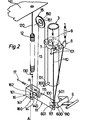
- Figure 2 shows the safety device in place in the frame 1.
- the permanent locking means of the column 3 are constituted by a brake 7 constantly applied, the release of which is controlled, by means of a plate 8 suspended by two springs 9 attached to the frame, by pressing on the pedal 6 connected to the plate 8 by two rods 10, engaged on the side of the pedal in a hook 110 of a lock 11.
- the means for balancing the weight of the mobile assembly - column 3 and work surface 4 - consist of a spring 12 hooked to the frame by an adjustable tensioner 120 fixed on a bracket 121, on the opposite, the spring 12 is attached to the end 130 of a cable 13.
- This cable 13 passes through the groove 140 of a first deflection pulley 14 and then into the helical groove 150 of a second deflection pulley 15 so as to catch on its other end 131 on a hook 300 fixed on the end of the column 3 opposite to that which supports the work surface 4.
- the axle 141 of the pulley 14 rotates freely in a stirrup 16 fixed on the frame 1 near its base 2; it is only held in the bottom of the stirrup 16 only by the tension of the cable 13. In the event of said cable breaking, the axle 141 leaves the stirrup by the effect of the weight of the pulley 14 since the axis of symmetry AA of the stirrup 16 is vertical and its opening 160 is oriented towards the base 2.
- the support 151 of the pulley 15 is fixed on the frame 1 at the point furthest from the stirrup 16 compatible with the height variation provided for positioning the worktop by sliding the column 3.
- the stirrup 16 comprises on the axis AA a guide 162 located at a distance from the bottom 161 determined by the width of the feeler 111 of the latch 11 and less than this.
- FIG. 3 represents the bolt 11 which provides the connection between the axle 141 of the first return pulley 14 and the pedal 6 for releasing the brake 7.
- This lock 11 is constituted by a single-piece plate formed by two parts 111, 112, of unequal width from a common linear base 113, the recess 114 comprising one of the attachment points 115 of a spring 17, the other being on the frame 1.
- the narrowest part 111, rounded at its free end 116, constitutes a feeler supported by the tension of the spring 17 between the guide 162 and the axle 141 of the pulley 14.
- the widest part 112 comprises, opposite the probe 111, two recesses 110, 117 superimposed, one 110, the most distant from the linear base 113, in the form of a hook, receives one of the ends 100 of the rod 10 for controlling the permanent blocking means of the column, the brake 7, the other end 101 of the rod 10 being connected to the plate 8 for releasing said brake.
- the other recess in the form of a notch 110 aligned on the axis of symmetry BB of the probe, receives a pin 600 fixed on the pedal 6, below the pivot points 601 thereof.
- FIG. 4 represents the action of the latch 11 in the event of the cable 13 breaking.
- the pulley 14 is no longer retained by the cable 13 in the stirrup 16, its axle 141 is pushed towards the opening 160 by the action of the feeler 111 pulled by the spring 17 under the guide 162.
- the latch 11 performs its recoil in the direction of the tensile force F of the spring 17 to the point where the recess 114 meets the stirrup 16.
- This movement of the lock 11 causes the pin 600 to come out of its notch 116 breaking the connection with the pedal 6.
- the release of the brake 7 cannot take place and the column 3 remains blocked in its initial position without breaking of the part.
Abstract
Description
- L'invention concerne un dispositif anti-chute pour l'immobilisation d'une colonne de table à dessin en cas de défaillance des moyens d'équilibrage du poids de l'ensemble mobile supportant un plan de travail et coulissant dans un bâti, les moyens de blocage permanent pouvant être temporairement desserrés en exerçant une pression sur une pédale extérieure au bâti lors du réglage en hauteur et en direction du plan de travail.
- Le document No.79 19256 décrit un dispositif de blocage et d'équilibrage d'un plan de travail d'une table à dessiner, supporté par une colonne centrale coulissant dans un support comportant des moyens de guidage et reposant sur une plaque de base constitué par au moins deux patins de frein diamétralement opposés par rapport à l'axe géométrique de la colonne coulissante, constamment appuyés par des moyens mécaniques contre la surface intérieure de ladite colonne et par un vérin à gaz prenant appui par une de ses extrémités sur la plaque de base, par l'autre extrémité, munie d'une poulie, sur un câble, caractérisé par le fait qu'un dispositif de sécurité est constitué par une bascule dont le pivot est fixé environ à mi-hauteur du support de la colonne. un des leviers de la bascule étant traversé par une tige de commande des patins de frein et portant un des points d'accrochage du câble, l'autre point d'accrochage du câble étant situé sur le bas de la colonne, l'autre levier de la bascule étant relié à un ressort compensateur ayant son point de tension fixé sur ledit support.
- Le but de l'invention consiste à réaliser un dispositif de sécurité plus simple, par conséquent moins onéreux qui réponde aux normes d'efficacité les plus strictes pour éviter une chute accidentelle de la planche en cas de défaillance des moyens d'équilibrage.
- A cette fin, l'ensemble mobile - colonne supportant le plan de travail - est relié aux moyens d'équilibrage par un câble, tendu à un bout par un ressort, passant sur une première poulie de renvoi dont l'essieu est supporté en rotation par un étrier fixé à la base du bâti, l'ouverture de cet étrier étant orientée vers l'assise du bâti, puis par une deuxième poulie de renvoi, à gorge hélicoïdale, fixée au sommet du bâti, l'autre bout du câble étant accroché à la colonne sur l'extrémité opposée à celle qui supporte le plan de travail.
- Un verrou assure une liaison entre l'essieu de la première poulie de renvoi, mobile dans son étrier, et la pédale de commande de desserrage des moyens de blocage permanent de la colonne de façon que ladite liaison soit instantanément interrompue par le relâchement ou la rupture du câble.
- Le verrou est une plaque d'une seule pièce formée de deux parties d'inégale largeur à partir d'une base linéaire commune, le décrochement comportant un des points d'attache d'un ressort l'autre étant sur le bâti, la partie la plus étroite, arrondie à son extrémité constituant un palpeur, la partie la plus large comportant, à l'opposé du palpeur, deux évidements superposés, l'un, le plus éloigné de la base linéaire, en forme de crochet, recevant la tringle de commande des moyens de blocage permanent de la colonne, l'autre, en forme d'encoche alignée sur l'axe de symétrie du palpeur, recevant une goupille de liaison du verrou avec la pédale de commande du desserrage desdits moyens de blocage.
- L'étrier supportant l'essieu de la première poulie de renvoi comporte, sur son axe de symétrie, un guide situé à une distance du fond de l'étrier inférieure à la largeur du palpeur du verrou.
- Un ressort, accroché d'une part au bâti d'autre part au verrou, exerce sur le verrou une force de traction nécessaire et suffisante pour maintenir l'extrémité arrondie du palpeur entre l'essieu de la première poulie de renvoi et le guide fixé sur l'étrier de façon qu'en cas de relâchement ou de rupture du câble, le verrou soit tiré par ledit ressort jusqu'à faire sortir de son encoche la goupille de liaison du verrou avec la pédale de commande.
- Le dispositif arrête instantanément le mouvement de l'ensemble mobile dès qu'intervient une rupture du câble ou d'une autre pièce formant la chaine cinématique de l'équilibrage.
- En combinaison avec des moyens de mise à hauteur du plan de travail par un desserrage temporaire des mâchoires de frein esserrant la colonne, si le câble se rompt au cours de cette manoeuvre, le verrou entrainé par un ressort met la pédale de commande, hors d'action et le frein est immédiatement resserré.
- D'autres avantages ressortiront de la description faite à titre d'exemple non limitatif d'une forme d'exécution de l'invention et du dessin dans lequel.
- La figure 1 est une vue d'ensemble de la table à dessiner;
- La figure 2 est une vue à plat du verrou;
- La figure 3 est un schéma du dispositif en position normale;
- La figure 4 est un schéma du dispositif après rupture du câble.
- La figure 1 représente une vue d'ensemble d'une table à dessin composée principalement d'un bâti 1, muni d'une embase 2, dans laquelle coulisse une colonne 3 supportant un plan de travail 4 par l'intermédiaire d'une ferrure d'orientation 5. Des moyens d'équilibrage du poids de l'ensemble mobile sont représentés en pointillés, pour mémoire. Les flèches a,b,c indiquent les trois orientations qui peuvent être données au plan de travail 4. Une pédale 6 située à l'extérieur du bâti juste au-dessus de l'embase 2 permet de desserrer les freins de blocage de la colonne mobile afin de mettre la table dans la position choisie. Ce dispositif de blocage est décrit dans le document No.82 16328.
- La figure 2 représente le dispositif de sécurité en place dans le bâti 1. Les moyens de blocage permanent de la colonne 3 sont constitués par un frein 7 constamment serré, dont le déblocage est commandé, au moyen d'une plaque 8 suspendue par deux ressorts 9 accrochés au bâti, par une pression sur la ,pédale 6 reliée à la plaque 8 par deux tringles 10, engagées du côté de la pédale dans un crochet 110 d'un verrou 11.
- Les moyens d'équilibrage du poids de l'ensemble mobile - colonne 3 et plan de travail 4 - sont constitués par un ressort 12 accroché au bâti par un tendeur 120 réglable fixé sur une équerre 121, à l'opposé, le ressort 12 est accroché au bout 130 d'un câble 13.
- Ce câble 13 passe dans la gorge 140 d'une première poulie de renvoi 14 puis dans la gorge hélicoïdale 150 d'une deuxième poulie de renvoi 15 pour venir s'accrocher par son autre bout 131 sur un crochet 300 fixé sur l'extrémité de la colonne 3 opposée à celle qui supporte le plan de travail 4.
- L'essieu 141 de la poulie 14 tourne librement dans un étrier 16 fixé sur le bâti 1 près de son embase 2; il n'est maintenu dans le fond de l'étrier 16 que par la tension du câble 13. En cas de rupture dudit câble, l'essieu 141 sort de l'étrier par l'effet du poids de la poulie 14 puisque l'axe de symétrie AA de l'étrier 16 est vertical et que son ouverture 160 est orientée vers l'embase 2. Le support 151 de la poulie 15 est fixé sur le bâti 1 au point le plus éloigné de l'étrier 16 compatible avec la variation de hauteur prévue pour le positionnement du plan de travail par le coulissement de la colonne 3.
- L'étrier 16 comporte sur l'axe AA un guide 162 situé à une distance du fond 161 déterminée par la largeur du palpeur 111 du verrou 11 et inférieure à celle-ci.
- La figure 3 représente le verrou 11 qui assure la liaison entre l'essieu 141 de la première poulie de renvoi 14 et la pédale 6 de desserrage du frein 7.
- Ce verrou 11 est constitué par une plaque d'une seule pièce formée de deux parties 111,112, d'inégale largeur à partir d'une base linéaire 113 commune, le décrochement 114 comportant un des points d'attache 115 d'un ressort 17, l'autre étant sur le bâti 1. La partie la plus étroite 111, arrondie à son extrémité libre 116, constitue un palpeur appuyé par la tension du ressort 17 entre le guide 162 et l'essieu 141 de la poulie 14.
- La partie la plus large 112 comporte à l'opposé du palpeur 111, deux évidements 110, 117 superposés, l'un 110, le plus éloigné de la base linéaire 113, en forme de crochet, reçoit une des extrémités 100 de la tringle 10 de commande des moyens de blocage permanent de la colonne, le frein 7, l'autre extrémité 101 de la tringle 10 étant reliée à la plaque 8 de desserrage dudit frein. L'autre évidement, en forme d'encoche 110 alignée sur l'axe de symétrie BB du palpeur, reçoit une goupille 600 fixée sur la pédale 6, en deçà des points de pivotement 601 de celle-ci.
- La figure 4 représente l'action du verrou 11 en cas de rupture du câble 13.
- La poulie 14 n'étant plus retenue par le câble 13 dans l'étrier 16, son essieu 141 est poussé vers l'ouverture 160 par l'action du palpeur 111 tiré par le ressort 17 sous le guide 162. Le verrou 11 effectue son recul dans le sens de la force F de traction du ressort 17 jusqu'au point de rencontre du décrochement 114 avec l'étrier 16. Ce déplacement du verrou 11 fait sortir la goupille 600 de son encoche 116 rompant la liaison avec la pédale 6. De ce fait, le desserrage du frein 7 ne peut avoir lieu et la colonne 3 reste bloquée dans sa position initiale sans rupture de pièce.
Claims (4)
Applications Claiming Priority (2)
| Application Number | Priority Date | Filing Date | Title |
|---|---|---|---|
| FR8314564 | 1983-09-07 | ||
| FR8314564A FR2551332B1 (fr) | 1983-09-07 | 1983-09-07 | Dispositif de securite pour l'immobilisation d'une colonne de table a dessin |
Publications (3)
| Publication Number | Publication Date |
|---|---|
| EP0140406A2 true EP0140406A2 (fr) | 1985-05-08 |
| EP0140406A3 EP0140406A3 (en) | 1985-06-19 |
| EP0140406B1 EP0140406B1 (fr) | 1987-05-06 |
Family
ID=9292171
Family Applications (1)
| Application Number | Title | Priority Date | Filing Date |
|---|---|---|---|
| EP84201253A Expired EP0140406B1 (fr) | 1983-09-07 | 1984-08-30 | Dispositif de sécurité pour l'immobilisation d'une colonne de table à dessin |
Country Status (6)
| Country | Link |
|---|---|
| US (1) | US4605189A (fr) |
| EP (1) | EP0140406B1 (fr) |
| JP (1) | JPS6072508A (fr) |
| AU (1) | AU559605B2 (fr) |
| DE (1) | DE3463439D1 (fr) |
| FR (1) | FR2551332B1 (fr) |
Cited By (2)
| Publication number | Priority date | Publication date | Assignee | Title |
|---|---|---|---|---|
| WO1998049921A1 (fr) * | 1997-05-06 | 1998-11-12 | Sis International A/S | Dispositif de verrouillage |
| CN114916772A (zh) * | 2022-05-27 | 2022-08-19 | 唐山师范学院 | 一种便捷式环境艺术设计用绘图辅助装置 |
Families Citing this family (30)
| Publication number | Priority date | Publication date | Assignee | Title |
|---|---|---|---|---|
| DE3511876A1 (de) * | 1985-04-01 | 1986-10-02 | Siemens AG, 1000 Berlin und 8000 München | Medizinische, insbesondere zahnmedizinische, einrichtung |
| GB8513899D0 (en) * | 1985-06-03 | 1985-07-03 | Karapita A D | Suspension system |
| US4807836A (en) * | 1988-03-15 | 1989-02-28 | Engineered Data Products, Inc. | Vertical and pivotal adjusting apparatus for drafting tables |
| DE4031105C2 (de) * | 1990-10-02 | 2000-03-09 | High Tech Geraetebau | Teleskopartig ausfahrbare Hubsäule, insbesondere zur Höhenverstellung einer Kamera |
| US5181620A (en) * | 1991-06-04 | 1993-01-26 | Weber-Knapp Company | Counterbalance mechanism |
| US5431112A (en) * | 1994-03-31 | 1995-07-11 | International Material Control Systems, Inc. | Safety locking system for air-operated tilt tables |
| US5572933A (en) * | 1994-03-31 | 1996-11-12 | International Material Control Systems Inc. | Safety locking system for air-operated tilt tables |
| US5868079A (en) * | 1996-10-16 | 1999-02-09 | Finish Group Ltd. | Stand for a monitor and a keyboard |
| US6382436B1 (en) * | 2000-09-28 | 2002-05-07 | Wen-Tsan Wang | Display rack |
| DE20019107U1 (de) * | 2000-11-12 | 2001-01-25 | Leica Microsystems | Stativ |
| US7032870B2 (en) * | 2000-11-28 | 2006-04-25 | Ergotron, Inc. | Methods and apparatus for generating force and torque |
| US6997422B2 (en) * | 2002-08-21 | 2006-02-14 | Ergotron, Inc. | Stand |
| US7252277B2 (en) | 2003-01-17 | 2007-08-07 | Ergotron, Inc. | Support arm |
| SG135015A1 (en) * | 2003-01-29 | 2007-09-28 | Inventio Ag | Device for monitoring cables of a lift |
| US20060185563A1 (en) * | 2004-07-30 | 2006-08-24 | Sweere Harry C | Lift mechanism systems and methods |
| US7825766B2 (en) | 2008-07-25 | 2010-11-02 | Cooper Technologies Company | Touch safe fuse module with ampacity rejection |
| US9267639B2 (en) | 2003-05-20 | 2016-02-23 | Ergotron, Inc | Lift mechanism systems and methods |
| US20050034547A1 (en) * | 2003-08-01 | 2005-02-17 | Sweere Harry C. | Mechanisms based on torque equalization principles |
| US20040250635A1 (en) * | 2003-05-20 | 2004-12-16 | Sweere Harry C. | Lift mechanism based on torque equalization principles |
| CN101442921B (zh) | 2004-12-17 | 2012-11-14 | 斯蒂尔凯斯发展股份有限公司 | 可调节高度的桌子 |
| US20070137535A1 (en) * | 2005-12-16 | 2007-06-21 | Steelcase Development Corporation | Load compensator for height adjustable table |
| US8228668B2 (en) | 2006-07-26 | 2012-07-24 | Ergotron, Inc. | Balanced moment lift system and method |
| CN104220801B (zh) | 2012-03-30 | 2017-07-21 | 爱格升有限公司 | 平衡提升机构及其方法 |
| KR101535672B1 (ko) * | 2012-05-01 | 2015-07-22 | 남광욱 | 발판을 구비한 클램핑 장치 |
| US20130306412A1 (en) * | 2012-05-16 | 2013-11-21 | Suspa Gmbh | Safety release |
| KR101633599B1 (ko) * | 2014-12-29 | 2016-06-30 | 남광욱 | 다리의 길이 조절장치 |
| TWM502129U (zh) * | 2015-02-16 | 2015-06-01 | Ming-Hsien Huang | 升降裝置 |
| CN106555923B (zh) * | 2015-09-24 | 2020-03-17 | 通用电气公司 | 一种显示器悬挂装置及显示器装置 |
| CN106671653B (zh) * | 2016-12-30 | 2018-05-18 | 苏州市测绘院有限责任公司 | 一种绘图用绘图板 |
| CN112178396B (zh) * | 2020-10-21 | 2022-07-22 | 上海森克电子科技有限公司 | 一种智能广告机底座对接机构 |
Citations (5)
| Publication number | Priority date | Publication date | Assignee | Title |
|---|---|---|---|---|
| DE1180103B (de) * | 1963-04-27 | 1964-10-22 | Clemens Riefler | Federausgleich fuer das Gewicht eines hoehen-verstellbaren Gegenstandes, z. B. eines Zeichenbrettes |
| DE2332225A1 (de) * | 1973-06-25 | 1975-01-09 | Kuhlmann Kg Franz | Sicherungssperre fuer einen zeichentisch |
| FR2351625A1 (fr) * | 1976-05-21 | 1977-12-16 | Oldor Sa | Perfectionnements aux tables a dessin actionnees par des mecanismes de soulevement, de blocage, d'abaissement et de reglage de l'inclinaison du plateau |
| FR2428419A1 (fr) * | 1978-06-13 | 1980-01-11 | Spoldzielnia Pracy Skala Wytwo | Verrouillage de securite d'une table a dessin industriel, avec equilibrage a ressort |
| FR2462125A2 (fr) * | 1979-07-26 | 1981-02-13 | Jeandal | Dispositif de blocage d'un plan de travail d'une table a dessiner |
Family Cites Families (9)
| Publication number | Priority date | Publication date | Assignee | Title |
|---|---|---|---|---|
| US2404949A (en) * | 1942-09-17 | 1946-07-30 | William H Murphy | Adjustable drafting stand |
| US3096059A (en) * | 1961-03-22 | 1963-07-02 | F And F Koenigkramer Company | Telescoping means having indexing, braking and interlocking means |
| US3213809A (en) * | 1964-01-13 | 1965-10-26 | Mayline Co | Adjustable table and brake mechanism therefor |
| US3358620A (en) * | 1965-08-24 | 1967-12-19 | Parigi Paolo | Drawing board or work table with raisable and inclinable working surface |
| US3370556A (en) * | 1966-10-25 | 1968-02-27 | Keuffel & Esser Co | Mechanical counterbalance system |
| FR1531447A (fr) * | 1967-04-11 | 1968-07-05 | Table à dessiner | |
| DE2646486C2 (de) * | 1976-10-14 | 1978-07-20 | Franz Kuhlmann Kg, Praezisionsmechanik Und Maschinenbau, 2940 Wilhelmshaven | Säulenzeichentisch mit Gewichtsausgleich durch eine Gasfeder |
| DE3003119C2 (de) * | 1979-02-12 | 1986-11-27 | Société Jeandal, Besancon | Vorrichtung zur Blockierung der Arbeitsfläche eines Zeichentisches |
| FR2533122B1 (fr) * | 1982-09-22 | 1986-08-29 | Alpia Sa | Dispositif de blocage d'une table a dessin |
-
1983
- 1983-09-07 FR FR8314564A patent/FR2551332B1/fr not_active Expired
-
1984
- 1984-08-16 US US06/641,499 patent/US4605189A/en not_active Expired - Fee Related
- 1984-08-22 AU AU32272/84A patent/AU559605B2/en not_active Ceased
- 1984-08-30 DE DE8484201253T patent/DE3463439D1/de not_active Expired
- 1984-08-30 EP EP84201253A patent/EP0140406B1/fr not_active Expired
- 1984-09-06 JP JP59185459A patent/JPS6072508A/ja active Granted
Patent Citations (5)
| Publication number | Priority date | Publication date | Assignee | Title |
|---|---|---|---|---|
| DE1180103B (de) * | 1963-04-27 | 1964-10-22 | Clemens Riefler | Federausgleich fuer das Gewicht eines hoehen-verstellbaren Gegenstandes, z. B. eines Zeichenbrettes |
| DE2332225A1 (de) * | 1973-06-25 | 1975-01-09 | Kuhlmann Kg Franz | Sicherungssperre fuer einen zeichentisch |
| FR2351625A1 (fr) * | 1976-05-21 | 1977-12-16 | Oldor Sa | Perfectionnements aux tables a dessin actionnees par des mecanismes de soulevement, de blocage, d'abaissement et de reglage de l'inclinaison du plateau |
| FR2428419A1 (fr) * | 1978-06-13 | 1980-01-11 | Spoldzielnia Pracy Skala Wytwo | Verrouillage de securite d'une table a dessin industriel, avec equilibrage a ressort |
| FR2462125A2 (fr) * | 1979-07-26 | 1981-02-13 | Jeandal | Dispositif de blocage d'un plan de travail d'une table a dessiner |
Cited By (2)
| Publication number | Priority date | Publication date | Assignee | Title |
|---|---|---|---|---|
| WO1998049921A1 (fr) * | 1997-05-06 | 1998-11-12 | Sis International A/S | Dispositif de verrouillage |
| CN114916772A (zh) * | 2022-05-27 | 2022-08-19 | 唐山师范学院 | 一种便捷式环境艺术设计用绘图辅助装置 |
Also Published As
| Publication number | Publication date |
|---|---|
| US4605189A (en) | 1986-08-12 |
| AU559605B2 (en) | 1987-03-12 |
| FR2551332B1 (fr) | 1987-04-17 |
| EP0140406A3 (en) | 1985-06-19 |
| JPH02922B2 (fr) | 1990-01-09 |
| JPS6072508A (ja) | 1985-04-24 |
| FR2551332A1 (fr) | 1985-03-08 |
| DE3463439D1 (en) | 1987-06-11 |
| EP0140406B1 (fr) | 1987-05-06 |
| AU3227284A (en) | 1985-05-30 |
Similar Documents
| Publication | Publication Date | Title |
|---|---|---|
| EP0140406B1 (fr) | Dispositif de sécurité pour l'immobilisation d'une colonne de table à dessin | |
| EP0561682A1 (fr) | Dispositif de sécurité pour ouvriers travaillant dans des endroits élevés | |
| FR2659861A1 (fr) | Dispositif support destine a recevoir un haltere muni de poids et pouvant etre manipule librement. | |
| WO2001061681A1 (fr) | Batte | |
| FR2758844A1 (fr) | Appareil pour la mise en place de plaques de plafond | |
| EP0090700B1 (fr) | Appareil pour le redressement de carrosseries d'automobiles ou similaires | |
| FR2715965A1 (fr) | Dispositif de sécurité contre la chute, en particulier pour portes basculantes. | |
| EP3720769A1 (fr) | Système de rappel pour crochet de charge et dispositif d'accrochage comportant un tel système | |
| CH626258A5 (fr) | ||
| BE511977A (fr) | ||
| EP0106388B1 (fr) | Dispositif de blocage d'une table à dessin | |
| FR2796344A1 (fr) | Mecanisme d'ancrage et d'articulation, notamment pour un siege arriere d'un vehicule automobile | |
| FR2653639A1 (fr) | Dispositif adaptable aux cannes a peche pour ferrage automatique. | |
| EP0081108A2 (fr) | Dispositif permettant le passage à distance d'un lien dans ou autour d'un organe d'accrochage | |
| FR2621295A1 (fr) | Dispositif d'accrochage automatique en position haute de la tete d'une voile d'un bateau a voile sur le mat de celui-ci | |
| EP0773181B1 (fr) | Dispositif de sécurité anti-chute pour un corps mobile | |
| FR2580902A1 (fr) | Dispositif d'accrochage, notamment pour la suspension de quartiers de viande. | |
| FR2462125A2 (fr) | Dispositif de blocage d'un plan de travail d'une table a dessiner | |
| FR2637505A1 (fr) | Tendeur de longes pour ceintures de travail sur des poteaux | |
| FR2520622A1 (fr) | Enrouleur de ceinture de securite a mecanisme de blocage a inertie | |
| FR2790968A1 (fr) | Bloqueur reglable pour la remontee le long d'une corde | |
| FR2685378A1 (fr) | Agencement de verrouillage notamment antipanique d'un organe mobile de fermeture d'une ouverture, tel qu'une porte. | |
| FR2522609A1 (fr) | Derailleur de pedalier pour cycle | |
| CH361646A (fr) | Dispositif automatique de sécurité destiné à coopérer avec des appareils de levage | |
| FR2503664A1 (fr) | Dispositif pour l'accrochage et le decrochage de charges placees sous des aeronefs |
Legal Events
| Date | Code | Title | Description |
|---|---|---|---|
| PUAI | Public reference made under article 153(3) epc to a published international application that has entered the european phase |
Free format text: ORIGINAL CODE: 0009012 |
|
| PUAL | Search report despatched |
Free format text: ORIGINAL CODE: 0009013 |
|
| AK | Designated contracting states |
Designated state(s): CH DE FR GB IT LI NL |
|
| AK | Designated contracting states |
Designated state(s): CH DE FR GB IT LI NL |
|
| 17P | Request for examination filed |
Effective date: 19850701 |
|
| GRAA | (expected) grant |
Free format text: ORIGINAL CODE: 0009210 |
|
| AK | Designated contracting states |
Kind code of ref document: B1 Designated state(s): CH DE FR GB IT LI NL |
|
| ITF | It: translation for a ep patent filed |
Owner name: BUGNION S.P.A. |
|
| REF | Corresponds to: |
Ref document number: 3463439 Country of ref document: DE Date of ref document: 19870611 |
|
| PLBE | No opposition filed within time limit |
Free format text: ORIGINAL CODE: 0009261 |
|
| STAA | Information on the status of an ep patent application or granted ep patent |
Free format text: STATUS: NO OPPOSITION FILED WITHIN TIME LIMIT |
|
| 26N | No opposition filed | ||
| PGFP | Annual fee paid to national office [announced via postgrant information from national office to epo] |
Ref country code: CH Payment date: 19900625 Year of fee payment: 7 |
|
| PGFP | Annual fee paid to national office [announced via postgrant information from national office to epo] |
Ref country code: DE Payment date: 19900629 Year of fee payment: 7 |
|
| PGFP | Annual fee paid to national office [announced via postgrant information from national office to epo] |
Ref country code: GB Payment date: 19900803 Year of fee payment: 7 |
|
| PGFP | Annual fee paid to national office [announced via postgrant information from national office to epo] |
Ref country code: FR Payment date: 19900827 Year of fee payment: 7 |
|
| ITTA | It: last paid annual fee | ||
| PGFP | Annual fee paid to national office [announced via postgrant information from national office to epo] |
Ref country code: NL Payment date: 19900831 Year of fee payment: 7 |
|
| PG25 | Lapsed in a contracting state [announced via postgrant information from national office to epo] |
Ref country code: GB Effective date: 19910830 |
|
| PG25 | Lapsed in a contracting state [announced via postgrant information from national office to epo] |
Ref country code: LI Effective date: 19910831 Ref country code: CH Effective date: 19910831 |
|
| PG25 | Lapsed in a contracting state [announced via postgrant information from national office to epo] |
Ref country code: NL Effective date: 19920301 |
|
| NLV4 | Nl: lapsed or anulled due to non-payment of the annual fee | ||
| GBPC | Gb: european patent ceased through non-payment of renewal fee | ||
| PG25 | Lapsed in a contracting state [announced via postgrant information from national office to epo] |
Ref country code: FR Effective date: 19920430 |
|
| REG | Reference to a national code |
Ref country code: CH Ref legal event code: PL |
|
| PG25 | Lapsed in a contracting state [announced via postgrant information from national office to epo] |
Ref country code: DE Effective date: 19920501 |
|
| REG | Reference to a national code |
Ref country code: FR Ref legal event code: ST |