EP0140633A2 - Method and apparatus for spectral transmissibility examination and analysis - Google Patents
Method and apparatus for spectral transmissibility examination and analysis Download PDFInfo
- Publication number
- EP0140633A2 EP0140633A2 EP84307038A EP84307038A EP0140633A2 EP 0140633 A2 EP0140633 A2 EP 0140633A2 EP 84307038 A EP84307038 A EP 84307038A EP 84307038 A EP84307038 A EP 84307038A EP 0140633 A2 EP0140633 A2 EP 0140633A2
- Authority
- EP
- European Patent Office
- Prior art keywords
- light
- optical
- body portion
- data
- breast
- Prior art date
- Legal status (The legal status is an assumption and is not a legal conclusion. Google has not performed a legal analysis and makes no representation as to the accuracy of the status listed.)
- Granted
Links
Images


Classifications
-
- A—HUMAN NECESSITIES
- A61—MEDICAL OR VETERINARY SCIENCE; HYGIENE
- A61B—DIAGNOSIS; SURGERY; IDENTIFICATION
- A61B5/00—Measuring for diagnostic purposes; Identification of persons
- A61B5/43—Detecting, measuring or recording for evaluating the reproductive systems
- A61B5/4306—Detecting, measuring or recording for evaluating the reproductive systems for evaluating the female reproductive systems, e.g. gynaecological evaluations
- A61B5/4312—Breast evaluation or disorder diagnosis
-
- A—HUMAN NECESSITIES
- A61—MEDICAL OR VETERINARY SCIENCE; HYGIENE
- A61B—DIAGNOSIS; SURGERY; IDENTIFICATION
- A61B5/00—Measuring for diagnostic purposes; Identification of persons
- A61B5/0059—Measuring for diagnostic purposes; Identification of persons using light, e.g. diagnosis by transillumination, diascopy, fluorescence
- A61B5/0082—Measuring for diagnostic purposes; Identification of persons using light, e.g. diagnosis by transillumination, diascopy, fluorescence adapted for particular medical purposes
- A61B5/0091—Measuring for diagnostic purposes; Identification of persons using light, e.g. diagnosis by transillumination, diascopy, fluorescence adapted for particular medical purposes for mammography
-
- A—HUMAN NECESSITIES
- A61—MEDICAL OR VETERINARY SCIENCE; HYGIENE
- A61B—DIAGNOSIS; SURGERY; IDENTIFICATION
- A61B5/00—Measuring for diagnostic purposes; Identification of persons
- A61B5/145—Measuring characteristics of blood in vivo, e.g. gas concentration, pH value; Measuring characteristics of body fluids or tissues, e.g. interstitial fluid, cerebral tissue
- A61B5/1455—Measuring characteristics of blood in vivo, e.g. gas concentration, pH value; Measuring characteristics of body fluids or tissues, e.g. interstitial fluid, cerebral tissue using optical sensors, e.g. spectral photometrical oximeters
Definitions
- This invention relates generally to the field of physiological examination and/or analysis of tissue, especially in vivo examination of human tissue, and also to the general field of optical (light) propagation and response technology, and to the application thereof; more particularly, the invention relates to methodology and apparatus involving the combination of these two such fields. Still more particularly, and in some of its more specific attributes, the invention relates to certain novel applications and methodology in examination of, and the production and presentation of clinical physiological data with respect to, human female breast anatomy by use of optical response observations, involving response measurements and characterization, and including spectral response by way of transmissibility, reflection and scatter aspects and relationships.
- light energy of particularly selected parameters is impinged upon or injected into the subject matter to be investigated and interpreted from the standpoint of the quantity or nature of the light detectable at another location, typically opposite the point of injection.
- This approach frequently includes the use of spectrometers at the point of detection, and may or may not involve the use of particularly-selected wavelengths of light for application to the subject under study.
- a typical approach would be to utilize a source of visible light coupled by a tubular shield or the like to a translucent body portion or object which is then viewed carefully from the opposite side with the human eye, often aided by various reflectors, magnifiers and the like.
- a source of visible light coupled by a tubular shield or the like to a translucent body portion or object which is then viewed carefully from the opposite side with the human eye, often aided by various reflectors, magnifiers and the like.
- One immediately-available example of such a procedure is that utilized by physicians for examination of human sinus conditions.
- An example of the more complex type of procedure would be a scientific study such as is illustrated in "Infrared Microspectrum of Living Muscle Cells", by Darwin L. Wood (Science, Vol.
- infrared oximeters have been developed and utilized in relatively recent years for non-invasive monitoring of the oxygenation of blood in humans and other specimens, most typically by contact with the ear or a finger extremity, a selected infrared wavelength being coupled to the involved body portion with detection occurring on the opposite side of such portion, variations in the light energy detected being directly indicative, after appropriate calibration, of the oxygen content of the blood flowing through the affected body portion, as a result of the known absorption references of particular infrared wavelengths by oxygenated haemoglobin.
- apparatus for obtaining clinical optical response data from selected body portions of individual subjects indicative of the intrinsic internal composition, condition and physiology of tissue within such body portions comprises: a manually-manipulatable test instrument having at least first and second component members and support means disposed therebetween for holding such members in selected mutually fixed relative positions; at least said first component member including light source means for emitting selected light from such member; said first component member being adapted to fit closely against a selected body portion from which clinical data is desired to be obtained, in a manner to project said emitted light into the interior of such body portion; light-receiving means carried by at least said second component member for receiving at least part of the light projected into said selected body portion; said support means including position-variable elements for movement of one of said component members relative to the other to change the effective optical path length between said source and said light-receiving means; and means operatively coupled between said light source means and said light-receiving means for providing a determination of the particular effective length of particular optical paths at various positions
- an optical probe for use in apparatus for obtaining physiological condition data from selected body portions of individual subjects, comprises: a generally rigid body defining a laterally-enclosed internal space and having a generally tubular nosecone at a forward end adapted to contact said selected body portions in light-sealing relation; a generally planar partition member disposed diametrically across said nosecone at a position spaced inward from the end extremity thereof, thereby walling off said internal space and providing a projecting tubularly-enclosed area; a septum extending forwardly from said partition member and dividing said tubularly-enclosed area; said nosecone, partition member and septum being substantially impervious to infrared and near infrared light; at least one light-detector means disposed at least partially within said tubularly-enclosed area and adjacent said septum; and signal-carrying cable means coupled to said light-detector means for transmitting light-reception signals therefrom, said cable means
- a method of obtaining clinical optical response data from selected body portions of living beings indicative of the intrinsic internal composition, condition and physiology of tissue within such body portions comprises: placing at least first and second optical probe members in physical contact with different areas on the surface of the selected body portion in a manner substantially precluding the escape or entry of light from between the optically-active portions of such probe members and the adjacent environment; using position-fixing support means at least in part to hold said optical probe members in their said position of physical contact, and determining the effective optical path length for said optically-active portions of said probe members while the latter are so held; sending selected light from at least one of said probe member active portions into the selected body portion which is in physical contact therewith, and receiving resulting light energy at least at the other probe member active portion; and quantifying and conditioning the said light energy received at said other probe member active portion, including using said determined effective optical path length to condition the light energy data for meaningful comparison with other such quantified and conditioned data obtained at other effective optical path lengths.
- the present invention rests upon a basic foundation of optical response characteristics, and physiological conditions and principles, generally including those expressed above but being more extensive in scope and modality as well as more expository in interpretation, and involving the effects of light scatter and transmissibility within the tissue under observation. That is, from one standpoint, the invention is broadly based upon the principle that light, and especially selected wavelengths of light (generally within the band of from 0.6 ⁇ m to 1.5j k m, by way of example, depending on the thickness of the subject) is transmissible through at least portions of the human body in varying degrees and in varying ways, involving significant variations in reflection and scatter effects.
- a given body will, when suffused with a selected light source (and particularly a sequence of selected light wavelengths), exhibit a definitive and repeatable optical response, e.g. response characteristics, which may be used to provide a "signature" or profile which demonstrates physiological condition and composition and, it is believed, shows abnormalities or anomalies, particularly when compared to other readings, e.g., profiles, taken from the same individual (i.e., person) both at other points in time and/or from other and complementary or analogous body portions (e.g., the opposite breast), as well as when compared to readings or profiles, and/or composites thereof, taken from the same body portions of other humans, especially related groupings of particular humans.
- a definitive and repeatable optical response e.g. response characteristics, which may be used to provide a "signature" or profile which demonstrates physiological condition and composition and, it is believed, shows abnormalities or anomalies, particularly when compared to other readings, e.g., profiles, taken from the same individual (i.
- the invention provides methodology and apparatus for obtaining optical response data indicative of intrinsic tissue characteristics and independent of individual and ethnic factors such as colour, degree of pigmentation, age, skin thickness, etc., which is uniquely useful in the above-noted type of approach, as well as in other and more general clinical ways.
- the invention provides methods and apparatus for obtaining spectral transmissibility data for clinical study and analysis, particularly of the human female breast, to provide a further clinical instrumentality for the study of the breast, hopefully to help bring about better understanding of its physiology, particularly with respect to the aging process, and also with respect to the occurrence and nature of anomaly, abnormality and hopefully of disease and/or other adverse conditions and states.
- the invention is directed to a new method and apparatus for obtaining optical response data profiles by examining biological tissue in vivo, and particularly the human female breast, yielding highly useful information as to the intrinsic composition, condition and physiology of an internal volume of tissue whose location and size depends upon the relative positioning and location of optical probes.
- the invention contemplates the injection of light (and particularly, sequential bursts of selected light wavelengths, or narrow bands) into the breast (or other selected body part) at a given location and the detection of the amount of resulting light which emerges and is detected, or received, at at least two locations, one relatively nearer the point of injection and one or more others located relatively farther from the injection point.
- the two detection locations are chosen to satisfy two conditions; i.e., the injected light must have similarly passed into and out of the skin at each different location, and the light must have sampled (propagated through) different areas and amounts of internal tissue.
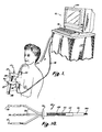
- FIG. 1 The general nature and general usage of one form of apparatus in accordance with the invention is illustrated pictorially in Figure 1. Stated in the most basic terms, optical measurements or readings are taken by use of a manually-manipulatable test instrument 10 which is coupled by cables 12 and 14 to a control unit 16 which includes an input keyboard 18 for actuation and control purposes, a CRT visual display 20 on which data may be displayed in various formats, and a housing 22 in the form of a cabinet which encloses associated light sources, electrical supply apparatus, data-handling electronics and data-processing apparatus including for example a microcomputer (which may be a small digital device of the type known as a "personal computer”, e.g., the IBM "P.C.” or generally similar device), together with interconnected data storage (e.g., floppy disk drive) and a digital plotter of a conventional nature.
- a microcomputer which may be a small digital device of the type known as a "personal computer", e.g., the IBM "P.C.” or generally
- test instrument 10 includes a first side or portion 24, referred to hereinafter as a "component member”, as well as a second such portion or component member 26, both of which are disposed in mutually-aligned opposition in this embodiment of the apparatus, and the mutual alignment (geometry) selected for the particular application is maintained by support means comprising, in this example, fixed and movable carriers 27, 27', respectively, mounted upon a rigid interconnecting alignment and positioning bar 28 which carries length-measurement indicia 29.
- support means comprising, in this example, fixed and movable carriers 27, 27', respectively, mounted upon a rigid interconnecting alignment and positioning bar 28 which carries length-measurement indicia 29.
- the movable carrier 27' to which component member 26 is attached, is slidable along the positioning bar 28, and a thumb screw or like securement means 30 is provided for fixing this carrier, and thus the component member 26 associated therewith, at a desired point of adjustment along the slide bar, at which the component members 24 and 26 have been positioned in the desired relationship relative to the subject, or patient.
- the slidable carrier 27' is maintained in a given desired geometric relationship (in this example, parallelism) with carrier 27, which may be fixed to the end of positioning bar 28, indexed at the "zero" position of the indicia 29, such that at any desired position along the length of the bar 28, the two component members 24 and 26 will be in consistent mutual alignment with one another (here involving certain axial relationships more particularly described hereinafter) and that such positioning will be retained upon tightening of the thumb screw or securement means 30.
- one relatively basic arrangement for axial relationships is that of a modified dial caliper, having the cross section of bar 28 in the form of a rectangle, and providing a complementary rectangular recess through movable carrier 27', such that the complementary shapes permit relative sliding yet maintain the desired alignment.
- a simple threaded thumb screw passing through a threaded aperture in the bottom portion of movable carrier 27' and aligned to bear against the adjacent edge of the bar 28 will serve as an entirely satisfactory indexing means, permitting the distance between the two carriers 27, 27' (and thus between the two component members 24, 26) to be fixed and easily read visually.
- optical path length information read from the indicia on the bar 28 will be explained more fully hereinafter, but it should be noted that the availability and utilization of this information is important. Thus, whatever spacial relationship or geometry is desired in a given embodiment, the support means utilized must be arranged to provide the effective optical path length, whether the component members are fixed or movable. In the embodiment just described, this information is entered into the computer via the keyboard 18 by the operator, but it may be preferred to utilize a form of the test instrument 10 having a transducer which automatically inputs this information as a coordinated part of the overall procedure.
- the test instrument 10 is utilized to place the two component members 24 and 26 on opposite sides of the breast or other body extremity which is to be examined.
- several different readings are preferably taken, for purposes discussed more fully hereinafter, at four positions: centrally of the breast and near the chest wall; on the inside edge or marginal extremity of the breast (i.e., on the side nearer the centre of the chest); along the outer marginal edge of the breast and generally across from the inside measurement just noted (both such measurements preferably being accomplished at a relative position somewhat further out from the chest wall than the first reading noted); and at a location which is generally centrally of the breast but as far outward from the chest wall as practicable, behind the nipple.
- the orientation of the test instrument, and of the two component members is preferably generally vertical in these different measurements or readings due to the interstructure of the breast, which is much more symmetrical from one vertical section to the next.
- the instrument is moved from place to place by manual manipulation, in each instance the two component members being moved apart to the extent necessary, placed over the breast in the desired positioning, and then gently moved toward one another to the extent necessary to provide full contact between the inner surface of each component member and the breast, so as to preclude the entry or exit of any light from between the breast and each of the component members.
- the component member 24 is seen in more detail in Figures 6, 7, 8 and 9.
- the structure of this member includes a cylindrical outer shell or cover 32 which is closed at one end (the rear, as referred to herein) by a circular connector deck 34, and which at its other end has a forwardly projecting cylindrical nosecone 36 whose central opening may be covered by an optical filter 38, an element primarily useful for environments having ambient lighting which would interfere with the optical responses to be obtained.
- a "safe light” may be used in combination with a complementary filter; e.g., a blue- green safe light where infrared light is most important, complemented by an orange filter as element 38.
- the outer shell or cover 32 may be a thin metal member, and the connector deck 34 may also be of metal, preferably brass or aluminium, to provide for optimum electrical grounding.
- the nosecone should be of a material which is opaque to infrared light energy, such as for example a filled epoxy, and the nosecone and outer shell should telescope snugly together and may be slightly tapered to enhance a close-fitting relationship.
- a generally flat support plate 40 which bottoms against the connector deck 34 on the one end and directly contacts a circular detector deck 42, to which it is secured in a desired manner, as by adhesive or screws, and the peripheral edge of the detector deck seats in and against the edges of an annular shoulder formed in the inside of the nosecone.
- the support plate 40 is likewise secured at its opposite end to the connector deck 34, which has a peripheral shoulder which snugly receives and seats the end of the outer cover 32, such that the entire assembly is a rigid unit, around which an annular upper portion of the carrier 27 fits, and is secured.
- an optical fibre cable or bundle 44 which enters through an appropriate aperture in the connector deck 34 and which projects forwardly, generally parallel to the support plate 40 (to which it may be secured by an appropriate clamp (not shown)), beyond which it passes through both the detector deck 42 and the filter plate 38, preferably terminating in a stainless steel or like ferrule 46.
- a pair of optical detectors 48 and 50 which seat within appropriate apertures in the detector deck 42 as well as in appropriate grooved or recessed portions in the end of the support plate 40.
- the detectors have electrical leads or conductors 52 which exit the component member through the connector deck 34, preferably through an appropriate connector 53.
- a thin plate-like septum 54 is fixed into position between the forward surface of the detector deck 42 and the rearward surface of the filter 38 to provide optical isolation of the detectors 48, 50 from the optical fibre bundle 40, and this effect is furthered by providing an arcuate reception slot 56 extending through the filter plate 38, through which light energy must pass in order to be received by either of the detectors 48 and 50.
- Arcuate slot 56 is in fact a segment of a circle which is centred upon the optical fibre 44 and the distance (radius) between the optical fibre cable and the reception slot should, in the embodiment under discussion, be in the range of about one to three centimetres, preferably not more than about two centimetres.
- the detectors 48 and 50 are "near" detectors which are intended to receive directly- returned "reflected” light energy, i.e., light which has been introduced ("injected") by the optical fibre bundle 44 into the particular body portion or extremity with respect to which clinical data is desired to be obtained, and which has in fact entered that body portion and has encountered initial reflection and "backscatter" from the internal tissue directly beneath the skin.
- the "reflected" light energy detected by "near” detectors 48 and 50 has passed through the skin of the subject to enter the internal tissue of the breast (or other body portion) but has immediately exited by passing back outward through the skin toward the source.
- This "near" detection signal is very important in accordance with the invention, as will be explained more fully hereinafter, and should not include light which has merely passed directly from the end of the fibre optic, over the end extremity of the septum 54, and directly into the detectors 48 and 50 without ever having passed into and out of the skin of the subject.
- the detected light energy should represent light reflected immediately back at the source, which has not traversed substantial distances within the breast tissue itself and emerged far away from the source; consequently, the reception slot 56 and the detectors 48 and 50 themselves should not be located more than the indicated distance from the point of light injection.
- the "direct transmission” (i.e. the "far") detector component 26 for the embodiment under discussion is illustrated in Figures 2, 3, 4 and 5.
- This member is substantially the same in basic structure as component 24 discussed above, including an outer shell 32', a circular connector deck 34' at the rear through which an electrical cable 14 enters and exits the component member, preferably via an appropriate connector 53'.
- a support plate 40' and a detector deck 42' are secured together generally in the manner discussed above with respect to component 24.
- detectors 58, 60, 62 and 64 are preferably present, i.e., detectors 58, 60, 62 and 64, all mounted generally in the manner referred to above with respect to detectors 48 and 50, i.e., protruding through the detector deck 42' and disposed within appropriate recesses in the forward end of the support plate 40'.
- component member 26 also includes a septum, designated 54', but in this case the septum separates and helps to optically isolate pairs of detectors, as best illustrated in Figure 5, detectors 58 and 64 being in one such pair and detectors 60 and 62 being in the other such pair.
- a filter plate such as that previously described (and designated by the numeral 38) may also be used if necessary, depending upon circumstances involved in the test environment, but is not included in Figures 2, 3 and 5.
- the present invention contemplates use of the overall optical response provided by comparative analysis of the "near" and “far” detection signals, which response is viewed as complex in nature and quite conceivably involving molecular (Rayleigh) scattering, particle (Mie) scattering, index (Fresnel and Christiansen Effect) scattering, fluorescence (especially infrared fluorescence), inelastic (Raman) scattering, and both spectral and non-spectral energy absorption.
- the circumstances and the methodology are considerably more complex than simple in vitro laboratory spectrophotometry, and the responses profiled in accordance herewith may well depend upon such factors as molecular structure, the types and size distributors of cells, the amount, nature and distribution of fat cells and of connective tissue, the blood supply and vascularization metabolism, the lymph system, and glandular activity.
- optical fibre cable 44 referred to above in conjunction with Figures 6, 7, 8 and 9 is seen in somewhat more detail in Figure 10, which illustrates that the aforementioned ferrule 46 terminates a brief distance inward from the actual end of the bundle of optical fibres 144, corresponding to the thickness of the filter plate 38.
- the main bundle 144 of optical fibres is preferably sheathed, as for example by a flexible helical conduit 66 extending over that portion outwardly of the cabinet 22 ( Figure 1) and an external sleeve 68 of plastic or the like may be utilized for stress relief.
- a mounting flange 70 is shown to illustrate a preferred structural attachment of the optical cable to the cabinet 22, and the portion of the cable which is to be disposed within the cabinet may simply be covered by protective cladding or lightweight tubing 72. As illustrated ( Figure 10) this latter portion may be divided into more than one branch (three being illustrated) in the event multiple light sources are to be utilized, each branch terminating in appropriate light-coupling optical terminals 73, 74 and 75, which may be physically sized differently from one another in a manner best suited to optically match the particular source to be coupled thereto.
- the component members 24 and 26 are,in the particular embodiment under discussion, held in direct alignment with one another by the carriers 27, 27' and the bar 28. More particularly, in this embodiment the alignment is such that the light-injecting fibre optic 44 is substantially aligned along the same axis with one pair of the "far" detectors, e.g., detectors 58 and 60, the other such pair of detectors thus being disposed a predetermined distance off-axis. This is for purposes of comparison and data-enhancement, as pointed out more fully below.
- one or more different light sources may be utilized to provide a relatively large number (on the order of about twenty) of different wavelength spectra (spectral groupings) within the total spectrum of about 0.5pm to perhaps 2.2 ⁇ m, and particularly within the range of about 0.6 to 1.5 ⁇ m, the wavelength resolution preferably being on the order of about 15 nanometres (nm) in the visible range and about 30 nm in the infrared range, which spectral array is conducted through the optical fibre cable 44 to the component member 24, from which the different light spectra are sequentially injected into the body portion under examination, e.g., a breast.
- each such source scans or steps through its particular different wavelength groupings one after another, with a relatively brief "dwell" for each particular different grouping.
- the various detectors will produce outputs in a corresponding sequence, each particular such output thus being correlated to and representing a measure of the intensity of the light energy received at a particular detector location as a result of a particular narrow wavelength grouping of light injected or admitted.
- use of scanning monochromators and an interference filter wheel are contemplated, for example in an arrangement where each provides a portion of the overall desired wavelength spectrum.
- An OCLI variable filter wheel may be the most preferable monochromator, at least for the "visible” light portion of the spectrum desired (and possibly for certain of the “near” infrared spectra) because of optical efficiencies provided which will increase the amount of light injected.
- the light sources themselves should be “chopped”, as by an optical shutter (rotating apertured disc), to reduce low- frequency background and “common mode” noise, and the detectors should thus be switched synchronously with the chopping of the sources.
- a tungsten filament quartz-halogen lamp may be utilized, with imaging of the filament onto the entrance apertures of the monochromators, with optical power input to the body portion under examination running from about 1.4 milliwatt at the lower end of the spectrum to about 1.9 milliwatt through the visible portion of the spectrum and perhaps on the order of about 3 to 3-1/2 milliwatts over the infrared portion of the spectrum (depending upon the thickness of the body portion being scanned).
- the optical filter selected for use should desirably augment the source over the infrared portion of the spectrum, with particular filters being cut to the various water windows and water absorption bands involved.
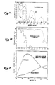
- FIG 12 An example of water content effect on a more general basis may be seen in Figure 12, in which the transmissibility of fused quartz of one metre length is illustrated for two different gradations or degrees of quartz purity, namely, two parts per thousand water (left-most curve) and three parts per million water (right curve).
- the fibre optic bundle used in accordance herewith should preferably be of the latter type, i.e., having very minimal water content.
- Figure 13 is further illustrative of conditions to be encountered, showing the general characteristics of, and marked differences between, the response of oxygenated hemoglobin on the one hand and reduced (oxygen depleted) hemoglobin on the other hand within the range of 600 nm to 850 nm, actual crossover of the response curves being present.
- a primary aim of the present invention is to obtain clinical, physiological data for selected body portions, and particularly of the female breast, by optical response methodology, and in a more particular sense, to obtain such clinical data on the basis of intrinsic, internal tissue properties; that is to say, to produce data which will be applicable from one individual to another, for widely-based comparison and classification.
- This requires that the data be free of the effects of invididual particularities such as for example, skin differences, including pigmentation, colour, thickness, etc., as well as breast thickness, and other particular physical characteristics.
- the above-disclosed method and apparatus for readily determining (reading out, or establishing in advance) the particular optical path length involved in a given measurement or scan is of surpassing importance, as is the determination and appropriate usage of both "direct” light transmission or propagation data (i.e., "far” data) as well as “reflective” (i.e., "near”) data.
- "direct" light transmission or propagation data i.e., "far” data
- reflective i.e., "near
- a significant feature of the present invention is the realization that "reflected” (i.e. "near") transmissibility data should be obtained and in effect used as a measure of the light energy actually injected into the interior of the body portion under examination, after the effects of impingement upon and passage through the skin, etc.
- optical path length is utilized in accordance with the invention to in effect further normalize or condition the data obtained and thus remove the otherwise-inherent variation of light energy propagation as a function of optical path length or thickness.
- optical path length is utilized in accordance with the invention to in effect further normalize or condition the data obtained and thus remove the otherwise-inherent variation of light energy propagation as a function of optical path length or thickness.
- optical path length the difference between such optical path lengths determined, since that difference (representing the different tissue volume sampled by the far receiver) is the essence of what is intended by the use of the term "optical path length" herein since in the particular example illustrated the close proximity of the near detector to the point of light injection may either be assumed to represent a zero path length for that detector or else the very short actual path length for it may be "built into” the scale read to determine the optical path length for the "far" detector.
- utilization of the measured or otherwise-determined effective or resultant optical path length is accomplished both by using it to compensate for inverse square reduction of propagated light intensity and also as the "thickness" parameter in application of the exponential function attributed to Beers and known as Beers' Law to develop intrinsic light propagation magnitude values for the internal tissue of the selected body portion.
- the resulting data may advantageously be displayed both by tables of magnitudes and by plotting the compensated and weighted magnitudes with respect to wavelength, not only by means of separate graphical presentations for each different location from which data is obtained, but also by taking complementary scans of complementary body portions, i.e., in the case of breast examinations, by taking a set of measurements for both breasts with similar relative positioning of the hand instrument 10, i.e., both left and right breasts along the inner (central) marginal edges, along the outer marginal edges, centrally near the chest wall, and centrally outward away from the chest wall.
- the resulting data provided in accordance with the invention may also be presented in the form of colour maps, by use of known colour-mapping programs commercially available for digital computers of the type referred to herein.
- the data obtained for particular wavelength groupings may be assigned different colours, and the colours overprinted within a map area as a function of received signal intensity after conditioning as described hereinabove.
- This will yield yet another form of data presentation which will have widely- differing colour content and distribution, according to the characteristics of the tissue sampled, which will have different evaluative effects for different persons which may be preferred by some.
- the formatted data may then be meaningfully compared to similarly formatted data for the same patient, and the records so obtained preserved for comparison with similar records taken at other points in time. Further, such results may be comparatively examined with respect to other results obtained from other particular individuals, both those who may be known to be "normal” (i.e., not known at that time to possess specific and identified abnormality or disease), as well as for those who may have diagnosed abnormality or illness.
- each of the "sets" or “pairs" of detectors at both the far transmission receiver, or component member, 26 and also at the near receiver or component member 24 are preferably comprised of two different types of detector elements, one of which is more effective over the shorter wavelength portion of the spectrum and the other of which is more effective over the longer wavelength portion, with an area of commonality or overlap in the mid-range.
- silicon photovoltaic cells are desirable for receiving the chopped "visible" light wavelengths of from about 0.5 to about 1.2/P, while lead sulphide (PbS) photoconductive cells provide some advantages in the higher, infrared wave length ranges, actually providing useful results throughout the range of from about 0.85 to about 2.2 ⁇ m, even though involving substantially higher noise production than the silicon photovoltaic cells.
- PbS lead sulphide
- a possible alternative to the lead sulphide cells (detectors), may be a zero-bias germanium photovoltaic cell, whose band gap is essentially midway between silicon and lead sulphide, and which may be cooled to lower the effective noise equivalent power.
- germanium detectors would not provide detection to the longer wavelengths over which lead sulphide is operative, but do have the advantage of having a peak response in the neighbourhood of about 1.5 ⁇ m, which may be at or near the only water transmissibility "window" beyond the 1.3 ⁇ m point.
- An alternative for the silicon photovoltaic cells is the silicon photodiode, having somewhat similar performance as the silicon photovoltaic cells, although they are presently deemed more preferred.
- the dual-detector configuration just noted not only serves to produce useful data over a greater wavelength spectrum, but also has the added feature of providing redundant data over a shared midrange.
- the absolute magnitudes of signals produced by the dissimilar types of detectors will be significantly different, but this of course may readily be balanced or compensated for by appropriate level-setting or gain-control procedures; consequently, the duplicative or redundant data produced over a certain portion of the transmitted wavelength spectrum, received at essentially the same position with respect to the light emitter or injector, is considered to be highly useful, since the data may be mutually compared to detect error sources, etc., and it may also be averaged together in order to increase accuracy and reliability.
- the four-detector set in the "far" or "direct transmission” receiver or component member 26 that is, the "on-axis" set of detectors (comprising two different types of detectors, as discussed above) samples data from a conceptually different point (i.e., coaxially with the fibre optic) than does the adjacent set of "off axis" detectors (which also comprise two different types of detectors).
- the data obtained from these two conceptually differing detection locations may also be compared and averaged or combined in the general manner discussed above with respect to the two different types of detectors, at each different detected wavelength, i.e., each different narrow wavelength band comprising a step or unit of the light injected into the body portion under examination by the fibreoptic cable.
- the output provided by each individual detector will comprise a series of magnitude or intensity readings measuring the amount of light energy received at that detector at the various points in time corresponding to the wavelength spectra produced by the light sources and injected into the body portion under examination.
- This analog-form electrical signal is conducted by the particular electrical lead or conductor within the electrical cable 14 which is associated with the particular detector involved.
- the component members 24 and 26 are, in the form illustrated, particularly sized to accommodate preamplifier circuitry, and additional processing circuitry if desired, within the enclosure or space 65 behind the detector element itself and alongside the support plate 40 in each component member.
- the resulting electrical signal which is at least initially of analog form, is coupled by the electrical cable 14 back to the control cabinet 22 noted previously, which includes signal-processing and computing electronics, as well as the display apparatus already noted hereinabove.
- the light detection may be accomplished through use of fibre optic receivers, with the received light energy conducted back through such fibre optic to the detection circuitry, where the detectors would then be located.
- Preferred signal-processing circuitry for the detector signals should include dedicated channels for each detector output, preferably of a type treating the detectors as current sources and including as entry-level components low-noise operational amplifiers such as the AD515H, to whose inverting input the detector output should be applied.
- This amplifier configuration will appear as a very low- impedance load to the detectors (essentially, a short circuit), and thus, with the operational amplifier connected in a current-feedback mode, virtually all of the signal strength will be shunted through the feedback resistor, such that the current output for the detectors will be linearly related to the input optical power.
- the detector outputs (which will, of course, reflect the chopping applied to the illumination sources) is preferably compressed by applying it to a logarithmic- function analog IC, following which it is converted to digital form by use of an A/D converter operated in a sampling mode at twice the chopping frequency and synchronized with the light source choppers.
- the logarithmic conversion before digitization although not strictly essential, serves to expand the dynamic range of the data obtained from the detectors.
- Reconversion to linear form may be accomplished by use of a digital anti-log IC, and the resulting data stream should be put through a subtraction stage in order to remove common mode (background) signal, after which the data should be averaged over a number of chopping cycles equal to one percent of the wavelength scan time.
- the final data for any given detector will consist of strings of repetitive bursts, each representing averaged detection signals from which background signal has been subtracted.
- a desirable addition, or alteration, of the signal-processing electronics described above is to demodulate the chopped signal and integrate the result over a number of the chopping cycles before the initial logarithmic conversion.
- the lead sulphide detectors it may be advisable to omit the logarithmic compression step, and go directly to the A/D conversion, due to the presence of substantial noise and the limited extent to which the total dynamic range they provide may be utilized, due to water absorption characteristics in living human tissue, particularly in actual in vivo examination of human anatomical portions.
- Table I An example of typical (if somewhat simplified) data to be obtained from actual clinical measurements done in accordance with the present invention is depicted in Table I immediately below, which should be understood as showing relative magnitudes of detector data obtained at four different examining positions, as identified, on both the right and the left breast of a human subject.
- the data in rows 2 and 6 was obtained near the chest wall at essentially the midportion of the breast, and the data in rows 4 and 8 was obtained at generally symmetrical upper and outer quadrant portions, rather than at the central and outer position identified above as now preferred for a fourth data-taking position.
- the numerical data presented may be taken as indicative of the maximum reading obtained by use of a single wavelength grouping or band under the indicated conditions, such maximal data (which is also representative of composite or weighted averaged data) having very evident significance even though being generalized or simplified when compared to the numerous individual readings at different wavelengths which the complete data scan described above would include.
- expressions such as "selected light wavelengths" are used generally in accordance herewith to designate any such procedure, regardless of how many wavelengths may actually be selected in a given application, and not merely to identify a procedure using all or a major portion of the particular wavelengths identified as making up the total useful spectrum for the methodology involved.
- Figure 14 illustrates another useful approach in presenting data obtained in accordance with the invention, providing a series of graphical "profiles" for each patient or individual on the basis of paired curves for each different position of the examination instrument, the two curves in each pair representing the data for the two breasts of the same patient obtained at the same position of examination.
- These pairs of curves may be displayed on the CRT screen 20 immediately after the corresponding scan has taken place, and/or they may be plotted out on paper in the general form here shown, for a permanent record.
- the data itself may also be stored in digital form on a suitable record, e.g., magnetic disc or tape.
- Figure 14 includes three individual sub-figures, designated 14a, 14b and 14c, each showing data readings obtained from a different subject (person) under clinical conditions, the three sets of data being generally illustrative of different physiological conditions likely to be encountered in the general population.
- each vertical column represents data obtained from a different person
- each horizontal row shows data obtained at the same general location each of the three different individuals.
- each individual graphical presentation there are separate traces or "curves" for each breast, the right breast data being shown in a darker, heavier line, and the left breast data being shown by a lighter, finer line, as indicated in the legend in the upper left-hand corner of the page (i.e., "Rt" and "Lt").
- Each individual curve or trace represents composite detector output signals obtained at a different examination wavelength or, more particularly, at a particular step in the examination scan comprising one increment of the entire examination wavelength spectrum.
- the ordinate represents detector output and wavelength is represented by the abscissa, although it is to be understood that such "detector output” comprises the intrinsic valuations referred to previously, involving compensation or conditioning based on optical path length and the "near" - “far” data resolution described above.
- the scale values for the ordinate and abscissa are not the same in the three different columns, the different curves having in effect been centred or partially centred in the available space for simplicity and uniformity in these drawings.
- the invention contemplates the presence of clinically efficacious modalities which may be useful for many purposes perhaps including diagnosis of particular conditions and/or illness
- a familiar and therefore non-threatening medium i.e., "light”
- relatively inexpensive apparatus operable by medical technicians as opposed to physicians themselves, primarily useful for indicating the need (or lack thereof) for much more intensive analytical investigation, i.e., mammography, ultrasound, biopsy, etc.
- both the tabular-type form of data presentation and the graphical-type format are considered useful and, as already indicated, the tabular format may be made much more comprehensive and diverse than that set forth for purposes of illustration hereinabove.
- Particular advantage is asserted with respect to the methodology involved in and epitomized by the graphical presentations of Figure 14, however, particularly with respect to the use of the different data-taking positions, the nature of the graphical format, and the comparative (paired) presentation.
Abstract
Description
- This invention relates generally to the field of physiological examination and/or analysis of tissue, especially in vivo examination of human tissue, and also to the general field of optical (light) propagation and response technology, and to the application thereof; more particularly, the invention relates to methodology and apparatus involving the combination of these two such fields. Still more particularly, and in some of its more specific attributes, the invention relates to certain novel applications and methodology in examination of, and the production and presentation of clinical physiological data with respect to, human female breast anatomy by use of optical response observations, involving response measurements and characterization, and including spectral response by way of transmissibility, reflection and scatter aspects and relationships.
- In academia, and particularly in biological and medical research activities, among practically innumerable studies, experiments and laboratory examinations, a relatively small but frequently recurring interest has been shown in the use of light, in various different forms, as an investigative and/or diagnostic tool or instrumentality. A relatively primitive emanation of this interest is evidenced in the various forms of transillumination which have been experimented with and used in many different ways over a great many years, probably dating back into antiquity, and in general utilizing light relatively crudely, i.e., as a visual aid, to help produce visually-perceptible shadows, shapes and images within or upon what would otherwise be substantially opaque objects or surfaces. In other more complex procedures, light energy of particularly selected parameters is impinged upon or injected into the subject matter to be investigated and interpreted from the standpoint of the quantity or nature of the light detectable at another location, typically opposite the point of injection. This approach frequently includes the use of spectrometers at the point of detection, and may or may not involve the use of particularly-selected wavelengths of light for application to the subject under study.
- Thus, in earlier efforts utilizing basic transillumination, a typical approach would be to utilize a source of visible light coupled by a tubular shield or the like to a translucent body portion or object which is then viewed carefully from the opposite side with the human eye, often aided by various reflectors, magnifiers and the like. One immediately-available example of such a procedure is that utilized by physicians for examination of human sinus conditions. An example of the more complex type of procedure would be a scientific study such as is illustrated in "Infrared Microspectrum of Living Muscle Cells", by Darwin L. Wood (Science, Vol. 1, July 13, 1951), in which different particular individual types of muscle fibres were placed between transparent plates and placed in the radiation beam of a microspectrometer, where they were subjected to various wavelengths of light up to about ten microns or micrometres (µm), with the detected transmission intensities being plotted according to wavelength. With respect to the efforts to use transillumination generally, further reference is made to the publication by M. Cutler, M.D., in the June, 1929, issue of Surgery, Gynecology and Obstetrics, entitled "Transillumination As An Aid In The Diagnosis Of Breast Lesions", and as to the more complex spectrophotometric procedures, reference is made to an article in the August 5, 1949, issue of Science (Vol. 110), by Blout and Mellors, entitled "Infrared Spectra Of Tissues".
- While the aforementioned article by Cutler discussed basic transillumination procedures for diagnosis of breast disease as early as 1929, a number of proposals for refinement and enhancement of the basic transillumination procedures have been suggested in intervening years. Thus, the use of colour film was proposed in 1972 by Gros and Hummel, and Ohlsson et al. proposed in 1980 the use of infrared film rather than ordinary colour film, both using visible yellow light as well as infrared or near infrared light as the illumination. Carlson has further proposed the use of a Vidicon system as a detector or collector, but the ultimate analysis and interpretation is nonetheless done visibly.
- In the area of spectrophotometric analytic and diagnostic efforts, infrared oximeters have been developed and utilized in relatively recent years for non-invasive monitoring of the oxygenation of blood in humans and other specimens, most typically by contact with the ear or a finger extremity, a selected infrared wavelength being coupled to the involved body portion with detection occurring on the opposite side of such portion, variations in the light energy detected being directly indicative, after appropriate calibration, of the oxygen content of the blood flowing through the affected body portion, as a result of the known absorption references of particular infrared wavelengths by oxygenated haemoglobin. Somewhat analogous observations and/or phenomena may be discerned by contemplation of the publication by Blout and Mellors, noted above, which noted a dramatic increase in the intensity of light at the 9.3JLm band in cancerous breast tissue as compared to normal breast tissue and the proposed explanation that the 9.3µm band is also one of the strong intensity bands for the enzyme ribonuclease, which rapidly increases in amount in rapidly proliferating cancer cells. Various publications of Frans Jobsis commencing in about 1977 and including US-A-4 223 680, 4 281 645, 4 321 930 and 4 380 240 are based upon a somewhat analogous although specifically different reported phenomenon, i.e., the spectrally distinctive absorption characteristics associated with the cellular enzyme cytachrome a, a31 which in turn is said to be integrally associated with, and indicative of, oxydative metabolism. On this basis, Jobsis proposed the use of a particularly-selected measuring wavelength and another carefully selected reference wavelength to produce apparent differences in detection level, which differences were said to demonstrate, and actually be indicative of, organ vitality or viability, since indicative of oxydative metabolism and therefore of oxygen sufficiency, the premise being that the chain of causation between the observed measurements and the body organ believed to be under investigation, i.e., internally subjected to the injected light, was complete and exclusive.
- The invention has various aspects, some only of which are set out in the claims now presented, others of which are set out in the Clauses appearing at the end of this description and immediately before the claims and yet others of which will be apparent from the statements of invention set out immediately below, the paragraphs following the heading "Brief Summary of the Present Invention" and from the remainder of the description following the heading "Detailed Description".
- According to one aspect of the present invention, apparatus for obtaining clinical optical response data from selected body portions of individual subjects indicative of the intrinsic internal composition, condition and physiology of tissue within such body portions, comprises: a manually-manipulatable test instrument having at least first and second component members and support means disposed therebetween for holding such members in selected mutually fixed relative positions; at least said first component member including light source means for emitting selected light from such member; said first component member being adapted to fit closely against a selected body portion from which clinical data is desired to be obtained, in a manner to project said emitted light into the interior of such body portion; light-receiving means carried by at least said second component member for receiving at least part of the light projected into said selected body portion; said support means including position-variable elements for movement of one of said component members relative to the other to change the effective optical path length between said source and said light-receiving means; and means operatively coupled between said light source means and said light-receiving means for providing a determination of the particular effective length of particular optical paths at various positions of said relative movement which effects change in such path length.
- According to a second aspect of the present invention, an optical probe for use in apparatus for obtaining physiological condition data from selected body portions of individual subjects, comprises: a generally rigid body defining a laterally-enclosed internal space and having a generally tubular nosecone at a forward end adapted to contact said selected body portions in light-sealing relation; a generally planar partition member disposed diametrically across said nosecone at a position spaced inward from the end extremity thereof, thereby walling off said internal space and providing a projecting tubularly-enclosed area; a septum extending forwardly from said partition member and dividing said tubularly-enclosed area; said nosecone, partition member and septum being substantially impervious to infrared and near infrared light; at least one light-detector means disposed at least partially within said tubularly-enclosed area and adjacent said septum; and signal-carrying cable means coupled to said light-detector means for transmitting light-reception signals therefrom, said cable means extending out of said body.
- According to a third aspect of the present invention, a method of obtaining clinical optical response data from selected body portions of living beings indicative of the intrinsic internal composition, condition and physiology of tissue within such body portions, comprises: placing at least first and second optical probe members in physical contact with different areas on the surface of the selected body portion in a manner substantially precluding the escape or entry of light from between the optically-active portions of such probe members and the adjacent environment; using position-fixing support means at least in part to hold said optical probe members in their said position of physical contact, and determining the effective optical path length for said optically-active portions of said probe members while the latter are so held; sending selected light from at least one of said probe member active portions into the selected body portion which is in physical contact therewith, and receiving resulting light energy at least at the other probe member active portion; and quantifying and conditioning the said light energy received at said other probe member active portion, including using said determined effective optical path length to condition the light energy data for meaningful comparison with other such quantified and conditioned data obtained at other effective optical path lengths.
- In a broad and underlying sense, the present invention rests upon a basic foundation of optical response characteristics, and physiological conditions and principles, generally including those expressed above but being more extensive in scope and modality as well as more expository in interpretation, and involving the effects of light scatter and transmissibility within the tissue under observation. That is, from one standpoint, the invention is broadly based upon the principle that light, and especially selected wavelengths of light (generally within the band of from 0.6µm to 1.5jkm, by way of example, depending on the thickness of the subject) is transmissible through at least portions of the human body in varying degrees and in varying ways, involving significant variations in reflection and scatter effects.
- Thus, it has been found that a given body will, when suffused with a selected light source (and particularly a sequence of selected light wavelengths), exhibit a definitive and repeatable optical response, e.g. response characteristics, which may be used to provide a "signature" or profile which demonstrates physiological condition and composition and, it is believed, shows abnormalities or anomalies, particularly when compared to other readings, e.g., profiles, taken from the same individual (i.e., person) both at other points in time and/or from other and complementary or analogous body portions (e.g., the opposite breast), as well as when compared to readings or profiles, and/or composites thereof, taken from the same body portions of other humans, especially related groupings of particular humans.
- Further, the invention provides methodology and apparatus for obtaining optical response data indicative of intrinsic tissue characteristics and independent of individual and ethnic factors such as colour, degree of pigmentation, age, skin thickness, etc., which is uniquely useful in the above-noted type of approach, as well as in other and more general clinical ways.
- More particularly, the invention provides methods and apparatus for obtaining spectral transmissibility data for clinical study and analysis, particularly of the human female breast, to provide a further clinical instrumentality for the study of the breast, hopefully to help bring about better understanding of its physiology, particularly with respect to the aging process, and also with respect to the occurrence and nature of anomaly, abnormality and hopefully of disease and/or other adverse conditions and states.
- In a broad sense, the invention is directed to a new method and apparatus for obtaining optical response data profiles by examining biological tissue in vivo, and particularly the human female breast, yielding highly useful information as to the intrinsic composition, condition and physiology of an internal volume of tissue whose location and size depends upon the relative positioning and location of optical probes.
- In a more particular sense, the invention contemplates the injection of light (and particularly, sequential bursts of selected light wavelengths, or narrow bands) into the breast (or other selected body part) at a given location and the detection of the amount of resulting light which emerges and is detected, or received, at at least two locations, one relatively nearer the point of injection and one or more others located relatively farther from the injection point. The two detection locations are chosen to satisfy two conditions; i.e., the injected light must have similarly passed into and out of the skin at each different location, and the light must have sampled (propagated through) different areas and amounts of internal tissue. By comparative analysis of the resulting light reception data, effects related to impingement and entry (as well as exiting) of the light through the skin are cancelled out, leaving only data which pertains to the internal tissue. Further, the geometrical locations and spacing of the light receivers is known and the optical path length, and particularly the optical path length difference between the location of the near receptor, or receiver, and that of the far receptor or receiver, is determined in accordance with the invention and used as a normalyzing factor in arriving at the light-reception data which is profiled. Thus, such data is appropriate for use in comparative studies of, and for averaging and compositing with respect to, different individuals regardless of whether they are of the same or different racial, ethnic or pigmentation characteristics, and regardless of particular physical differences and the like, from one subject to another.
- The invention may be carried into practice in various ways but one form of apparatus embodying the invention and various methods and procedures in which the apparatus is used will now be described by way of example with reference to the accompanying drawings, in which:
- Figure 1 is a pictorial perspective view showing the apparatus and depicting its general manner of use;
- Figure 2 is an enlarged, sectional side elevation of the direct-transmission receiver component member of the apparatus;
- Figure 3 is a sectional, side elevation of the component member shown in Figure 2, taken along the plane III-III thereof;
- Figure 4 is an end elevation of the component member shown in Figure 3, as seen along the plane IV-IV thereof;
- Figure 5 is a sectional, end elevation taken along the plane V-V of Figure 2;
- Figure 6 is an enlarged, sectional side elevation similar to Figure 2 but showing the light- transmission and reflectance-receiver component member;
- Figure 7 is a sectional, side elevation taken through the plane VII-VII of Figure 6;
- Figure 8 is an end elevational view of the structure seen in Figure 7;
- Figure 9 is a sectional, end elevation taken along the plane IX-IX of Figure 6;
- Figure 10 is a fragmentary, plan view, on a reduced scale, showing a fibre optic cable assembly for use in interconnecting portions of the apparatus;
- Figure 11 is a graphical representation showing light-transmissibility characteristics of water;
- Figure 12 is a graphical representation showing light-transmissibility characteristics of fused quartz;
- Figure 13 is a graphical representation showing light-transmissibility characteristics of hemoglobin; and
- Figure 14 is a three-part graphical representation showing preferred ways of visually presenting spectrophotometric physiological data in accordance with the present invention.
- The general nature and general usage of one form of apparatus in accordance with the invention is illustrated pictorially in Figure 1. Stated in the most basic terms, optical measurements or readings are taken by use of a manually-
manipulatable test instrument 10 which is coupled bycables control unit 16 which includes aninput keyboard 18 for actuation and control purposes, a CRTvisual display 20 on which data may be displayed in various formats, and ahousing 22 in the form of a cabinet which encloses associated light sources, electrical supply apparatus, data-handling electronics and data-processing apparatus including for example a microcomputer (which may be a small digital device of the type known as a "personal computer", e.g., the IBM "P.C." or generally similar device), together with interconnected data storage (e.g., floppy disk drive) and a digital plotter of a conventional nature. - With continuing reference to Figure 1, it will be observed that the
test instrument 10 includes a first side orportion 24, referred to hereinafter as a "component member", as well as a second such portion orcomponent member 26, both of which are disposed in mutually-aligned opposition in this embodiment of the apparatus, and the mutual alignment (geometry) selected for the particular application is maintained by support means comprising, in this example, fixed andmovable carriers 27, 27', respectively, mounted upon a rigid interconnecting alignment andpositioning bar 28 which carries length-measurement indicia 29. The movable carrier 27', to whichcomponent member 26 is attached, is slidable along thepositioning bar 28, and a thumb screw or like securement means 30 is provided for fixing this carrier, and thus thecomponent member 26 associated therewith, at a desired point of adjustment along the slide bar, at which thecomponent members carrier 27, which may be fixed to the end ofpositioning bar 28, indexed at the "zero" position of the indicia 29, such that at any desired position along the length of thebar 28, the twocomponent members - While many different particular structures or mechanisms might well be utilized for the basic purpose of maintaining a given desired geometric relationship, i.e., "alignment", of the two component members while permitting any desired relative movement, one relatively basic arrangement for axial relationships is that of a modified dial caliper, having the cross section of
bar 28 in the form of a rectangle, and providing a complementary rectangular recess through movable carrier 27', such that the complementary shapes permit relative sliding yet maintain the desired alignment. In such an arrangement, a simple threaded thumb screw passing through a threaded aperture in the bottom portion of movable carrier 27' and aligned to bear against the adjacent edge of thebar 28 will serve as an entirely satisfactory indexing means, permitting the distance between the twocarriers 27, 27' (and thus between the twocomponent members 24, 26) to be fixed and easily read visually. - The significance of the optical path length information read from the indicia on the
bar 28 will be explained more fully hereinafter, but it should be noted that the availability and utilization of this information is important. Thus, whatever spacial relationship or geometry is desired in a given embodiment, the support means utilized must be arranged to provide the effective optical path length, whether the component members are fixed or movable. In the embodiment just described, this information is entered into the computer via thekeyboard 18 by the operator, but it may be preferred to utilize a form of thetest instrument 10 having a transducer which automatically inputs this information as a coordinated part of the overall procedure. - As may further be seen in Figure 1, the
test instrument 10 is utilized to place the twocomponent members - The
component member 24 is seen in more detail in Figures 6, 7, 8 and 9. As seen there, the structure of this member includes a cylindrical outer shell or cover 32 which is closed at one end (the rear, as referred to herein) by acircular connector deck 34, and which at its other end has a forwardly projectingcylindrical nosecone 36 whose central opening may be covered by anoptical filter 38, an element primarily useful for environments having ambient lighting which would interfere with the optical responses to be obtained. For example, under such conditions a "safe light" may be used in combination with a complementary filter; e.g., a blue- green safe light where infrared light is most important, complemented by an orange filter aselement 38. The outer shell or cover 32 may be a thin metal member, and theconnector deck 34 may also be of metal, preferably brass or aluminium, to provide for optimum electrical grounding. The nosecone should be of a material which is opaque to infrared light energy, such as for example a filled epoxy, and the nosecone and outer shell should telescope snugly together and may be slightly tapered to enhance a close-fitting relationship. Inside theouter shell 32 and thenosecone 36 is a generallyflat support plate 40 which bottoms against theconnector deck 34 on the one end and directly contacts acircular detector deck 42, to which it is secured in a desired manner, as by adhesive or screws, and the peripheral edge of the detector deck seats in and against the edges of an annular shoulder formed in the inside of the nosecone. Thesupport plate 40 is likewise secured at its opposite end to theconnector deck 34, which has a peripheral shoulder which snugly receives and seats the end of theouter cover 32, such that the entire assembly is a rigid unit, around which an annular upper portion of thecarrier 27 fits, and is secured. - Inside the
component member 24 is the forward end extremity of an optical fibre cable orbundle 44, which enters through an appropriate aperture in theconnector deck 34 and which projects forwardly, generally parallel to the support plate 40 (to which it may be secured by an appropriate clamp (not shown)), beyond which it passes through both thedetector deck 42 and thefilter plate 38, preferably terminating in a stainless steel or likeferrule 46. Also, within thecomponent member 24, is a pair ofoptical detectors detector deck 42 as well as in appropriate grooved or recessed portions in the end of thesupport plate 40. The detectors have electrical leads orconductors 52 which exit the component member through theconnector deck 34, preferably through anappropriate connector 53. At the forward end of the component member, a thin plate-like septum 54 is fixed into position between the forward surface of thedetector deck 42 and the rearward surface of thefilter 38 to provide optical isolation of thedetectors optical fibre bundle 40, and this effect is furthered by providing anarcuate reception slot 56 extending through thefilter plate 38, through which light energy must pass in order to be received by either of thedetectors Arcuate slot 56 is in fact a segment of a circle which is centred upon theoptical fibre 44 and the distance (radius) between the optical fibre cable and the reception slot should, in the embodiment under discussion, be in the range of about one to three centimetres, preferably not more than about two centimetres. This distance is important, since in this embodiment thedetectors optical fibre bundle 44 into the particular body portion or extremity with respect to which clinical data is desired to be obtained, and which has in fact entered that body portion and has encountered initial reflection and "backscatter" from the internal tissue directly beneath the skin. - Thus, the "reflected" light energy detected by "near"
detectors septum 54, and directly into thedetectors reception slot 56 and thedetectors - The "direct transmission" (i.e. the "far")
detector component 26 for the embodiment under discussion is illustrated in Figures 2, 3, 4 and 5. This member is substantially the same in basic structure ascomponent 24 discussed above, including an outer shell 32', a circular connector deck 34' at the rear through which anelectrical cable 14 enters and exits the component member, preferably via an appropriate connector 53'. Withincomponent 26 is a support plate 40' and a detector deck 42', all secured together generally in the manner discussed above with respect tocomponent 24. In the case of this "far" component member, however, four detectors are preferably present, i.e.,detectors detectors component member 24,component member 26 also includes a septum, designated 54', but in this case the septum separates and helps to optically isolate pairs of detectors, as best illustrated in Figure 5,detectors detectors component member 26, a filter plate such as that previously described (and designated by the numeral 38) may also be used if necessary, depending upon circumstances involved in the test environment, but is not included in Figures 2, 3 and 5. - It should be understood that terms used herein such as "direct" or "transmitted" and "reflected" or "scatter" are adopted primarily for purposes of convenience and illustration, and not to indicate that there are fundamental differences between the light energy that emerges at any given point from the selected body portion after injection. Actually, it is believed that all injected light undergoes multiple and diverse scatter effects throughout its tortuous path of propagation within the breast or other body portion into which it has been injected. Thus, the present invention contemplates use of the overall optical response provided by comparative analysis of the "near" and "far" detection signals, which response is viewed as complex in nature and quite conceivably involving molecular (Rayleigh) scattering, particle (Mie) scattering, index (Fresnel and Christiansen Effect) scattering, fluorescence (especially infrared fluorescence), inelastic (Raman) scattering, and both spectral and non-spectral energy absorption. Thus, the circumstances and the methodology are considerably more complex than simple in vitro laboratory spectrophotometry, and the responses profiled in accordance herewith may well depend upon such factors as molecular structure, the types and size distributors of cells, the amount, nature and distribution of fat cells and of connective tissue, the blood supply and vascularization metabolism, the lymph system, and glandular activity.
- The
optical fibre cable 44 referred to above in conjunction with Figures 6, 7, 8 and 9 is seen in somewhat more detail in Figure 10, which illustrates that theaforementioned ferrule 46 terminates a brief distance inward from the actual end of the bundle ofoptical fibres 144, corresponding to the thickness of thefilter plate 38. Themain bundle 144 of optical fibres is preferably sheathed, as for example by a flexiblehelical conduit 66 extending over that portion outwardly of the cabinet 22 (Figure 1) and anexternal sleeve 68 of plastic or the like may be utilized for stress relief. A mounting flange 70 is shown to illustrate a preferred structural attachment of the optical cable to thecabinet 22, and the portion of the cable which is to be disposed within the cabinet may simply be covered by protective cladding orlightweight tubing 72. As illustrated (Figure 10) this latter portion may be divided into more than one branch (three being illustrated) in the event multiple light sources are to be utilized, each branch terminating in appropriate light-couplingoptical terminals - As indicated previously in conjunction with the discussion of Figure 1, the
component members carriers 27, 27' and thebar 28. More particularly, in this embodiment the alignment is such that the light-injectingfibre optic 44 is substantially aligned along the same axis with one pair of the "far" detectors, e.g.,detectors - In accordance with a particular aspect of the invention, one or more different light sources may be utilized to provide a relatively large number (on the order of about twenty) of different wavelength spectra (spectral groupings) within the total spectrum of about 0.5pm to perhaps 2.2µm, and particularly within the range of about 0.6 to 1.5µm, the wavelength resolution preferably being on the order of about 15 nanometres (nm) in the visible range and about 30 nm in the infrared range, which spectral array is conducted through the
optical fibre cable 44 to thecomponent member 24, from which the different light spectra are sequentially injected into the body portion under examination, e.g., a breast. That is, each such source scans or steps through its particular different wavelength groupings one after another, with a relatively brief "dwell" for each particular different grouping. Accordingly,the various detectors will produce outputs in a corresponding sequence, each particular such output thus being correlated to and representing a measure of the intensity of the light energy received at a particular detector location as a result of a particular narrow wavelength grouping of light injected or admitted. With respect to particular examples of light sources, use of scanning monochromators and an interference filter wheel are contemplated, for example in an arrangement where each provides a portion of the overall desired wavelength spectrum. An OCLI variable filter wheel may be the most preferable monochromator, at least for the "visible" light portion of the spectrum desired (and possibly for certain of the "near" infrared spectra) because of optical efficiencies provided which will increase the amount of light injected. The light sources themselves should be "chopped", as by an optical shutter (rotating apertured disc), to reduce low- frequency background and "common mode" noise, and the detectors should thus be switched synchronously with the chopping of the sources. - Somewhat more particularly, with respect to the particular source of illumination, a tungsten filament quartz-halogen lamp may be utilized, with imaging of the filament onto the entrance apertures of the monochromators, with optical power input to the body portion under examination running from about 1.4 milliwatt at the lower end of the spectrum to about 1.9 milliwatt through the visible portion of the spectrum and perhaps on the order of about 3 to 3-1/2 milliwatts over the infrared portion of the spectrum (depending upon the thickness of the body portion being scanned). The optical filter selected for use should desirably augment the source over the infrared portion of the spectrum, with particular filters being cut to the various water windows and water absorption bands involved. That is, as illustrated in Figure 11, it is known that contrary to what a lay person might expect, ordinary water has the property of varying transmissibility to light, having several very pronounced "absorption bands", i.e., strong light-absorption characteristics, at particular wavelength bands, separated by "windows" in which the transmissibility increases markedly between the preceding absorption band and the next succeeding one.
- Referring more particularly to Figure 11, considering the transmissibility of water for varying distances at wavelengths from .8µm to about 2.5µm, at distances ranging from 1 millimetre (top curve), 3 millimetres (second from top curve), 10 millimetres (second curve from bottom) and 30 millimetres (lowermost curve), strong absorption bands will be seen to exist over areas designated Al, A2 and A3, occurring at approximately .9-1.0µm, 1.4-1.5µm, and 1.9-2.1µm. Between these absorption bands, strong transmissibility "windows" may be seen at approximately 1.0-1.1µm, 1. 2-1.3µm, 1.7-1.8 and at about 2.2µm. The absorption bands and transmissibility windows will thus be seen to produce striking results, since at transmission distances of 1 millimetre and 3 millimetres, light is substantially fully absorbed at wavelengths of approximately 1.5µm and approximately 2.0µm, but a very strong (by comparison) transmissibility band exists between these wavelengths.
- These characteristics have more than casual significance to methodology such as is contemplated herein, since the human body is of course comprised of a preponderance of water, and transmissibility characteristics of human tissue must therefore be anticipated as exhibiting somewhat similar characteristics, or in any event as encompassing the same technological phenomenon. In this respect however, it should be noted that different types of tissue embody different water content; for example fatty tissue has much less water and it is less tightly bound by the molecules; thus, fat tissue exhibits much greater optical transmissibility per unit thickness than does glandular tissue, for example. That is, the type of water binding involved in the tissue of a particular body portion will significantly affect the optical response, particularly transmissibility, since tightly-bound water has a much different response than weakly-bound or free water. An example of water content effect on a more general basis may be seen in Figure 12, in which the transmissibility of fused quartz of one metre length is illustrated for two different gradations or degrees of quartz purity, namely, two parts per thousand water (left-most curve) and three parts per million water (right curve). In view of this, it should be understood that the fibre optic bundle used in accordance herewith should preferably be of the latter type, i.e., having very minimal water content. Figure 13 is further illustrative of conditions to be encountered, showing the general characteristics of, and marked differences between, the response of oxygenated hemoglobin on the one hand and reduced (oxygen depleted) hemoglobin on the other hand within the range of 600 nm to 850 nm, actual crossover of the response curves being present.
- As may well be perceived by contemplation of Figures 11, 12 and 13, attempted optical (light transmission) examination procedures in living tissue will inevitably be highly affected, even to the extent of obscuring meaningful results, if accountability of water absorption and oxyhemoglobin characteristics is not fully considered. In particular, the water absorption windows must be taken into account, preferably by eliminating the effects from the test instrumentality itself (i.e., choosing optical fibres having the least adverse response), and by the aforementioned approach of selecting the optical filters on the basis of the water absorption bands and transmissibility windows. A further and analogous consideration is the noted absorption characteristics of oxygenated and reduced hemoglobin, which is of course present in great abundance in living human tissue and which should thus be similarly taken into account, either by avoidance or by appropriate compensation in the analysis of the resulting data.
- To a substantial degree, a primary aim of the present invention is to obtain clinical, physiological data for selected body portions, and particularly of the female breast, by optical response methodology, and in a more particular sense, to obtain such clinical data on the basis of intrinsic, internal tissue properties; that is to say, to produce data which will be applicable from one individual to another, for widely-based comparison and classification. This requires that the data be free of the effects of invididual particularities such as for example, skin differences, including pigmentation, colour, thickness, etc., as well as breast thickness, and other particular physical characteristics. Such an achievement is of fundamental importance in pursuit of the particular type of methodology involved here (i.e., optical response analysis or study of living subjects, and in particular of living human subjects), since without these essential refinements, there can be no truly meaningful correlation between any two different individuals having a normal range of individual differences.
- In accomplishing the aforementioned objective, the above-disclosed method and apparatus for readily determining (reading out, or establishing in advance) the particular optical path length involved in a given measurement or scan is of surpassing importance, as is the determination and appropriate usage of both "direct" light transmission or propagation data (i.e., "far" data) as well as "reflective" (i.e., "near") data. With respect to the second such point, a significant feature of the present invention is the realization that "reflected" (i.e. "near") transmissibility data should be obtained and in effect used as a measure of the light energy actually injected into the interior of the body portion under examination, after the effects of impingement upon and passage through the skin, etc. From this "near" detection level is subtracted the "far" or "direct-transmission" data, since by so doing one may compare the amount of light energy which has passed completely through, or at least traversed a substantial portion of, the breast or other body portion to the amount of light energy actually injected into the internal tissue initially, and thus remove from consideration all of the many data-modifying characteristics arising from individual differences of skin. This in effect provides data which is truly a gauge of intrinsic, internal tissue characteristics, which may be accurately correlated with similar data taken from other different body locations and/or other individuals.
- Furthermore, the knowledge and appropriate utilization of the particular optical path length involved in each different optical scan over whatever different wavelength spectra have been selected and over whatever different body portion or path has been selected is similarly of great significance, since optical path length is utilized in accordance with the invention to in effect further normalize or condition the data obtained and thus remove the otherwise-inherent variation of light energy propagation as a function of optical path length or thickness. In this connection, it should be clearly understood that the particular arrangement illustrated, with axial alignment of the receivers and close positioning of the "near" detector to the light source, is not at all the only effective such arrangement. That is, while at least one "near" and one "far" detector are required, they need not be positioned on a straight-line basis if some other (e.g. relative angular positioning with respect to the light source) arrangement is desired, as for example to better accommodate a particular anatomical area to be studied. In any such arrangement, the effective optical paths involved for the particular positions of the receivers must be determined, and the difference between such optical path lengths determined, since that difference (representing the different tissue volume sampled by the far receiver) is the essence of what is intended by the use of the term "optical path length" herein since in the particular example illustrated the close proximity of the near detector to the point of light injection may either be assumed to represent a zero path length for that detector or else the very short actual path length for it may be "built into" the scale read to determine the optical path length for the "far" detector. In any case, utilization of the measured or otherwise-determined effective or resultant optical path length is accomplished both by using it to compensate for inverse square reduction of propagated light intensity and also as the "thickness" parameter in application of the exponential function attributed to Beers and known as Beers' Law to develop intrinsic light propagation magnitude values for the internal tissue of the selected body portion.
- While it is not the purpose of this disclosure to focus upon any particular methodology and/or apparatus for actually making this data compensation or specifically implementing the data-conditioning principles, it may be noted that data-handling procedures of this general nature are readily and indeed routinely obtained through use of known techniques and routines in the use of digital computers, and that appropriate results may also be obtained directly through electrical signal-processing approaches, in hardware (circuitry), since discrete digital components such as adders, subtracters and digital dividers are of course in widespread use and of widely diverse availability. It is the general underlying principle and methodology of such approaches which is here involved, i.e., arrival at intrinsic-type data by conditioning the signal values actually received from the "far" receivers in the "direct transmission" mode through use of the "near" receiver "reflectance transmission" data, together with use of the optical path length for each particular measurement set.
- Further aspects of the methodology involved in the present case are the aforementioned concepts of taking multiple different data scans at different predetermined positions on the same body portion (in particular, the human breast), as well as on comparable or complementary body portions on the same person (e.g. the opposite breast) and by use of similar scans taken at like positions on like portions of other persons (and including averaged or composite such scans, classified as by age or condition for example) all obtained by use of the same or substantially the same spectral transmissibility procedures, involving numerous different wavelengths of light with resulting multiple data points on a wavelength-specific basis, with subsequent presentation of the resulting data in the form of graphical or tabular profiles for study and consideration in documenting the characteristics of a given person at a given point in that person's life, together with the analysis for determination of individual characteristics and anomalies present at the time of the particular scan or set of readings.
- In this respect, the resulting data, to be commented upon more specifically herebelow, may advantageously be displayed both by tables of magnitudes and by plotting the compensated and weighted magnitudes with respect to wavelength, not only by means of separate graphical presentations for each different location from which data is obtained, but also by taking complementary scans of complementary body portions, i.e., in the case of breast examinations, by taking a set of measurements for both breasts with similar relative positioning of the
hand instrument 10, i.e., both left and right breasts along the inner (central) marginal edges, along the outer marginal edges, centrally near the chest wall, and centrally outward away from the chest wall. The resulting data provided in accordance with the invention may also be presented in the form of colour maps, by use of known colour-mapping programs commercially available for digital computers of the type referred to herein. For example, the data obtained for particular wavelength groupings may be assigned different colours, and the colours overprinted within a map area as a function of received signal intensity after conditioning as described hereinabove. This will yield yet another form of data presentation which will have widely- differing colour content and distribution, according to the characteristics of the tissue sampled, which will have different evaluative effects for different persons which may be preferred by some. Regardless of which particular form of data presentation is selected, the formatted data may then be meaningfully compared to similarly formatted data for the same patient, and the records so obtained preserved for comparison with similar records taken at other points in time. Further, such results may be comparatively examined with respect to other results obtained from other particular individuals, both those who may be known to be "normal" (i.e., not known at that time to possess specific and identified abnormality or disease), as well as for those who may have diagnosed abnormality or illness. - A further point in the foregoing connection involving the particular methodology and apparatus disclosed herein, relates to the use of duplicative or dual reception means at the different locations in the
component members component member 24 are preferably comprised of two different types of detector elements, one of which is more effective over the shorter wavelength portion of the spectrum and the other of which is more effective over the longer wavelength portion, with an area of commonality or overlap in the mid-range. For example, silicon photovoltaic cells are desirable for receiving the chopped "visible" light wavelengths of from about 0.5 to about 1.2/P, while lead sulphide (PbS) photoconductive cells provide some advantages in the higher, infrared wave length ranges, actually providing useful results throughout the range of from about 0.85 to about 2.2µm, even though involving substantially higher noise production than the silicon photovoltaic cells. A possible alternative to the lead sulphide cells (detectors), may be a zero-bias germanium photovoltaic cell, whose band gap is essentially midway between silicon and lead sulphide, and which may be cooled to lower the effective noise equivalent power. Such germanium detectors would not provide detection to the longer wavelengths over which lead sulphide is operative, but do have the advantage of having a peak response in the neighbourhood of about 1.5µm, which may be at or near the only water transmissibility "window" beyond the 1.3µm point. An alternative for the silicon photovoltaic cells is the silicon photodiode, having somewhat similar performance as the silicon photovoltaic cells, although they are presently deemed more preferred. - The dual-detector configuration just noted not only serves to produce useful data over a greater wavelength spectrum, but also has the added feature of providing redundant data over a shared midrange. To be sure, the absolute magnitudes of signals produced by the dissimilar types of detectors will be significantly different, but this of course may readily be balanced or compensated for by appropriate level-setting or gain-control procedures; consequently, the duplicative or redundant data produced over a certain portion of the transmitted wavelength spectrum, received at essentially the same position with respect to the light emitter or injector, is considered to be highly useful, since the data may be mutually compared to detect error sources, etc., and it may also be averaged together in order to increase accuracy and reliability. This same goal is served by providing the four-detector set in the "far" or "direct transmission" receiver or
component member 26; that is, the "on-axis" set of detectors (comprising two different types of detectors, as discussed above) samples data from a conceptually different point (i.e., coaxially with the fibre optic) than does the adjacent set of "off axis" detectors (which also comprise two different types of detectors). The data obtained from these two conceptually differing detection locations may also be compared and averaged or combined in the general manner discussed above with respect to the two different types of detectors, at each different detected wavelength, i.e., each different narrow wavelength band comprising a step or unit of the light injected into the body portion under examination by the fibreoptic cable. Other techniques which take further advantage of the dual-dissimilar detector configuration are for example, a sequence of blocking first one and then the other with optical filters at selected points in the wavelength transmission spectrum, to provide greater flexibility and certainty for data-comparison and evaluation techniques. Where more than one specific light source is utilized, as for example two different monochromators, such blocking and filtering techniques may be utilized to ensure transmission channel separation. It should be further noted that the silicon photovoltaic cells preferred for detection at the lower portion of the spectrum require a lower "chopping" frequency of the light source than do the lead sulphide photoconductive cells, due to the higher capacity of the silicon cells. For example, a useful frequency for use with the silicon cells is on the order of 13 Hz, whereas an optimum chopping frequency for the lead sulphide cells is on the order of about 220 Hz. - As will be understood, the output provided by each individual detector will comprise a series of magnitude or intensity readings measuring the amount of light energy received at that detector at the various points in time corresponding to the wavelength spectra produced by the light sources and injected into the body portion under examination. This analog-form electrical signal is conducted by the particular electrical lead or conductor within the
electrical cable 14 which is associated with the particular detector involved. In this connection, it is to be noted that thecomponent members space 65 behind the detector element itself and alongside thesupport plate 40 in each component member. The resulting electrical signal, which is at least initially of analog form, is coupled by theelectrical cable 14 back to thecontrol cabinet 22 noted previously, which includes signal-processing and computing electronics, as well as the display apparatus already noted hereinabove. Alternatively, it should be noted, the light detection may be accomplished through use of fibre optic receivers, with the received light energy conducted back through such fibre optic to the detection circuitry, where the detectors would then be located. - Preferred signal-processing circuitry for the detector signals should include dedicated channels for each detector output, preferably of a type treating the detectors as current sources and including as entry-level components low-noise operational amplifiers such as the AD515H, to whose inverting input the detector output should be applied. This amplifier configuration will appear as a very low- impedance load to the detectors (essentially, a short circuit), and thus, with the operational amplifier connected in a current-feedback mode, virtually all of the signal strength will be shunted through the feedback resistor, such that the current output for the detectors will be linearly related to the input optical power. After such amplification, the detector outputs (which will, of course, reflect the chopping applied to the illumination sources) is preferably compressed by applying it to a logarithmic- function analog IC, following which it is converted to digital form by use of an A/D converter operated in a sampling mode at twice the chopping frequency and synchronized with the light source choppers. The logarithmic conversion before digitization, although not strictly essential, serves to expand the dynamic range of the data obtained from the detectors. Reconversion to linear form may be accomplished by use of a digital anti-log IC, and the resulting data stream should be put through a subtraction stage in order to remove common mode (background) signal, after which the data should be averaged over a number of chopping cycles equal to one percent of the wavelength scan time. Thus, the final data for any given detector will consist of strings of repetitive bursts, each representing averaged detection signals from which background signal has been subtracted.
- A desirable addition, or alteration, of the signal-processing electronics described above is to demodulate the chopped signal and integrate the result over a number of the chopping cycles before the initial logarithmic conversion. In the case of the lead sulphide detectors, it may be advisable to omit the logarithmic compression step, and go directly to the A/D conversion, due to the presence of substantial noise and the limited extent to which the total dynamic range they provide may be utilized, due to water absorption characteristics in living human tissue, particularly in actual in vivo examination of human anatomical portions. This is particularly true with respect to the female breast, which undergoes almost constant physiological change both on a day- to-day monthly basis and, to a much greater extent, over a lifetime, there being great differences in the relative amount of water present from time to time, as well as in its form, which may be free or "bound", e.g., in protein molecules.
- An example of typical (if somewhat simplified) data to be obtained from actual clinical measurements done in accordance with the present invention is depicted in Table I immediately below, which should be understood as showing relative magnitudes of detector data obtained at four different examining positions, as identified, on both the right and the left breast of a human subject. In this instance, the data in
rows 2 and 6 was obtained near the chest wall at essentially the midportion of the breast, and the data inrows 4 and 8 was obtained at generally symmetrical upper and outer quadrant portions, rather than at the central and outer position identified above as now preferred for a fourth data-taking position. Also, instead of obtaining individual data readings at many different wavelengths, the numerical data presented may be taken as indicative of the maximum reading obtained by use of a single wavelength grouping or band under the indicated conditions, such maximal data (which is also representative of composite or weighted averaged data) having very evident significance even though being generalized or simplified when compared to the numerous individual readings at different wavelengths which the complete data scan described above would include. In either event, expressions such as "selected light wavelengths" are used generally in accordance herewith to designate any such procedure, regardless of how many wavelengths may actually be selected in a given application, and not merely to identify a procedure using all or a major portion of the particular wavelengths identified as making up the total useful spectrum for the methodology involved.
- Consideration of the data in the above Table will readily reveal the significance of the readings as a general indicator of condition. Thus, in comparing the readings in rows 1 and 5, for example, for the outer third of the right breast in comparison to the left breast, the differences in numerical magnitude shown reveal graphic differences in the underlying physiological conditions. Further significance can be drawn by comparing in a relative manner the "direct" (or "far") transmission data and the "reflection" (or "near") transmission data at each given sampling station, and for the same station on opposite breasts. The actual numerical ratio of "direct" transmission data to "reflection" transmission data is indicated in the third column of figures, and differences here are readily apparent upon casual examination; the same is certainly true with respect to the figures in the fourth column, which are the overall percentile averages of data for
rows - Figure 14 illustrates another useful approach in presenting data obtained in accordance with the invention, providing a series of graphical "profiles" for each patient or individual on the basis of paired curves for each different position of the examination instrument, the two curves in each pair representing the data for the two breasts of the same patient obtained at the same position of examination. These pairs of curves may be displayed on the
CRT screen 20 immediately after the corresponding scan has taken place, and/or they may be plotted out on paper in the general form here shown, for a permanent record. Of course, the data itself may also be stored in digital form on a suitable record, e.g., magnetic disc or tape. - Figure 14 includes three individual sub-figures, designated 14a, 14b and 14c, each showing data readings obtained from a different subject (person) under clinical conditions, the three sets of data being generally illustrative of different physiological conditions likely to be encountered in the general population. In these sub-figures, each vertical column represents data obtained from a different person, and each horizontal row shows data obtained at the same general location each of the three different individuals. In each individual graphical presentation there are separate traces or "curves" for each breast, the right breast data being shown in a darker, heavier line, and the left breast data being shown by a lighter, finer line, as indicated in the legend in the upper left-hand corner of the page (i.e., "Rt" and "Lt"). Each individual curve or trace represents composite detector output signals obtained at a different examination wavelength or, more particularly, at a particular step in the examination scan comprising one increment of the entire examination wavelength spectrum. In these graphical presentations, the ordinate represents detector output and wavelength is represented by the abscissa, although it is to be understood that such "detector output" comprises the intrinsic valuations referred to previously, involving compensation or conditioning based on optical path length and the "near" - "far" data resolution described above. Also, the scale values for the ordinate and abscissa are not the same in the three different columns, the different curves having in effect been centred or partially centred in the available space for simplicity and uniformity in these drawings. Thus, in actual practice, different curves plotted on the same continuous and consistent basis would show even greater differences for different patients since the location of the curves will be considerably different from one with respect to the field defined by the ordinate and abscissa, depending upon the physiological conditions encountered.
- Considering the graphical representations of Figure 14 in somewhat more detail, it will be noted that the two different tracings for the right and left breast, respectively, appear very symmetrical in the left column (Figure 14a); indeed, the two traces are very nearly in registration with one another in almost all areas, apart from some magnitude differences in the top reading, obtained at the "inner" position (i.e., centre of the breast and near the chest wall). Even so, the relative shape of the traces very much resemble one another, with the exception of some very slight divergence for the "outer" position (centre of the breast and away from the chest wall) at the longer wavelengths. Some of the same general observations may be made with respect to the clinical data presented in the centre column (Figure 14b), although it will be noted that the two traces do not come into such close registration, and there are more differences in the shape of one curve compared to the other. These general characterizations are much less true with respect to the data presented in the right-hand column (Figure 14c), in which some readily apparent and significant divergence in curve shape is present, portions of the two different curves actually having oppositely- directed slopes of considerable steepness. Even from considering the curves in this rather superficial manner, and making even such generalized observations, it may not be surprising to learn that the actual patients involved were, in the case represented by columns 14a and 14b, relatively "normal" women of different ages and different breast composition (e.g., different amounts of glandular and/or fibrous connective tissue as compared to fat); in the case represented by column 14c, however, the data represents an older woman diagnosed medically as having certain breast abnormality or anomaly in each breast, of which that on the right side appeared more serious.
- It is believed self-evident that consideration of the results indicated above demonstrates not only the presence of meaningful data but also the potential of a highly useful methodology. In this respect it is not the purpose of this specification to assert a complete, comprehensive and finalized description and explanation of all of the very complex physical and chemical factors involved in the propagation of light through living tissue, nor for every meaningful aspect of the data obtained by the method and apparatus disclosed; further, it is not intended to teach complete and definitive methodology for specific medical diagnosis. Instead, it is intended to show highly useful methods and apparatus for clinical examination and study of human subjects, and for presentation of the data so achieved, including comparative presentations for similar positions on different but analogous body portions of the same patient, and for a broad cross section of different patients at both the same and different ages, and also with respect to particular patients at various different points in their lifespan. Thus, while the invention contemplates the presence of clinically efficacious modalities which may be useful for many purposes perhaps including diagnosis of particular conditions and/or illness, it is presently contemplated that perhaps the most useful contribution of the invention is to provide a screening device and modality in which a familiar and therefore non- frightening medium (i.e., "light") is utilized in a harmless and noninvasive procedure made possible by relatively inexpensive apparatus operable by medical technicians as opposed to physicians themselves, primarily useful for indicating the need (or lack thereof) for much more intensive analytical investigation, i.e., mammography, ultrasound, biopsy, etc. In this respect, both the tabular-type form of data presentation and the graphical-type format are considered useful and, as already indicated, the tabular format may be made much more comprehensive and diverse than that set forth for purposes of illustration hereinabove. Particular advantage is asserted with respect to the methodology involved in and epitomized by the graphical presentations of Figure 14, however, particularly with respect to the use of the different data-taking positions, the nature of the graphical format, and the comparative (paired) presentation.
- It should be noted that the foregoing specification and appended drawings disclose concepts and methodologies principally described herein as applicable to study of the human female breast, but which are not at all limited to use for this purpose. That is, optical response and particularly spectral response data profiling in the manner described herein in definitely considered to be appropriate for, and valuable in, examination of other body portions, human or otherwise. While it may or may not be true that a given such application may call for slightly varying the specifics of the modality in actual application, the basic underlying concepts should nonetheless prove applicable and effective.
- While the invention is defined in a number of aspects in the following claims, the invention may also be defined in a number of further aspects by the following clauses.
- A. A method of appraising the condition, composition and/or physiological state of selected body portions of living beings by optical response, comprising the steps of: placing at least first and second optical probe members (24, 26) in physical contact with the surface of the selected body portion at a plurality of different mutually-spaced positions thereon, in a manner substantially precluding the escape or entry of light from between the optically-active portions of such probe members and the adjacent environment; holding said optical probe members fixed in each of their said positions of physical contact, and establishing a measure of the effective optical path length between said optically-active portions of said probe members while the latter are so held in each of said positions; sending selected light from at least one of said probe member active portions into the selected body portion which is in physical contact therewith and receiving resulting light energy at least at the other probe member active portion at each of said different positions; using the effective optical path length measure established for each such position to condition the light energy data received for each such position, and mutually comparing the conditioned light energy data obtained at the various different positions and different effective optical path lengths.
- B. A method of optically appraising according to Clause A including the steps of sending selected wavelengths of said light into the selected body portion, correlating individual component parts of the said conditioned light energy data obtained for individual instances of the said different optical probe positions with the particular selected light wavelength for which such individual data component parts are responsive and representative, and using such correlated data component parts and particular selected wavelengths as the basis for said step of mutually comparing the conditioned light energy data obtained at the various different positions and optical path lengths.
- C. A method of optically appraising according to Clause B including the step of graphically plotting coordinates representative of at least certain of said correlated data component parts and their corresponding wavelengths for different ones of said positions, and performing said step of mutually comparing by contrasting one or more such graphical plots with others thereof.
- D. A method of optically appraising according to any of Clauses A to C and applied to human female breast anatomy, wherein said first and second optical probe members are placed generally opposite one another on the top and bottom surfaces of a breast, respectively, and moved from one to another particular location on said top and bottom surfaces, said one and another particular locations on said top and bottom breast surfaces comprising said plurality of different positions on the surface of the selected body portion.
- E. A method of appraising according to Clause D wherein said particular locations include at least one at the outer side portion of the breast and at least one generally centrally of that same breast.
- F. A method of appraising according to Clause B and applied to human female breast anatomy, including the steps of sequentially placing said first and second optical probe members in a plurality of particular different mutually-spaced positions on each breast of the same human subject, with the said particular positions on one breast generally corresponding to those on the other; holding said optical probe members in fixed position at each of such positions and establishing said effective optical path length for each; carrying on said steps of sending selected wavelengths of light and receiving resulting light energy at each of said plurality of particular positions on both breasts, and using the particular effective optical path length established for each such position to condition the light energy data received at each such position; and including the step of mutually comparing the conditioned light energy data obtained for various ones of said particular different positions on one breast with the conditioned data obtained for the generally corresponding positions on the other breast.
- G. A method according to Clause F including the steps of correlating individual component parts of the said conditioned light energy data for individual ones of the said different positions and effective optical path lengths with the particular selected light wavelength for which such individual data component parts are responsive and representative, and using such correlated data component parts and particular selected wavelengths as the basis for said step of mutually comparing the conditioned light energy data obtained for the various different positions and different effective optical path lengths.
- H. A method according to Clause G including the step of graphically plotting coordinates representative of at least certain of said correlated data component parts and their respective wavelengths for selected corresponding positions on the two different breasts of the same human subject, said step of mutually comparing being carried out by contrasting such graphical plots for at least one set of corresponding positions on opposite breasts of the same subject.
- I. A method according to Clause H in which the step of graphically plotting coordinates is carried on for a plurality of sets of said selected corresponding positions on the two opposite breasts.
- J. A method according to any of Clauses A to I including the step of receiving said resulting light energy from said body portion at at least two locations for at least certain of said different positions, one such location being relatively near that at which said light is sent into said body portion at said one optical probe member and another such location being relatively farther from that where said light is sent into said body portion; and using a representation of said resulting light energy received at said relatively near location as a conditioning factor for the said resulting light energy data received at said relatively far location, to condition such data for optical effects on the received light resulting from impingement of the light upon and passage thereof through the outer perimeter of the selected body portion at the place of light entry, in addition to using the effective optical path length established for said optical probe positions to condition the data for light energy received by said other optical probe member at such positions.
- K. A method according to Clause J including the steps of sending selected wavelengths of said light into the selected body portion, correlating individual component parts of the said conditioned light energy data obtained for individual instances of the said different optical probe positions with the particular selected light wavelength for which such individual data component parts are responsive and representative, and using such correlated data component parts and particular selected wavelengths as coordinates to graphically plot the conditioned light energy data obtained at the various different positions and different effective optical path lengths.
- L. A method of appraising the physiological state of selected body portions of living beings, comprising the steps of: placing first and second optical probe members in physical contact with a plurality of relatively different mutually-spaced positions on the surface of the same selected body portion for a plurality of different such living beings, in a manner substantially precluding the escape or entry of light from between the optically-active portions of such probe members and the adjacent environment; holding said first and second optical probe members fixed in each of their said positions of physical contact, and determining the effective optical path length between said optically-active portions of said probe members while the latter are so held in each of said positions; sending selected light from at least one of said probe member active portions into the selected body portion which is in physical contact therewith, and receiving resulting light energy at the other probe member active portion at each of said different positions; using said determined effective optical path length for each such position to condition the light energy data received at each such position; receiving said resulting light energy from said body portion at a location relatively near that at which said selected light is sent into said body portion at said one optical probe member as well as receiving said resulting light energy at said other optical probe member, at least at certain of said different positions; using a representation of said resulting light energy received at said relatively near location as a conditioning factor for the said resulting light energy data received at said other optical probe member to condition such data for optical effects on the received light resulting from impingement of the light upon and passage thereof through the outer perimeter of the selected body portion at the place of light entry, in addition to using the effective optical path length determined for each of said certain optical probe positions to also condition the data for light energy received by said other optical probe member at such positions; and mutually comparing the conditioned light energy data obtained at the various different positions and different effective optical path lengths for one such living being with like conditioned data obtained at like positions on other such living individuals.
- M. A method according to Clause L in which said step of mutually comparing the conditioned optical data from different living individuals is done by graphically plotting data components from a given such individual which correspond to particular selected wavelengths of light sent into the particular body portion of that individual and to which such data components correspond, and by comparing one such plot from one such individual with other such plots from other individuals.
- N. A method according to Clause M in which said step of comparing one such plot with others thereof comprises comparing the plot of data obtained for a selected body portion of a particular one such living individual with a composite plot prepared by combining the data obtained for the same selected body portion of a plurality of different living individuals.
Claims (20)
Priority Applications (1)
| Application Number | Priority Date | Filing Date | Title |
|---|---|---|---|
| AT84307038T ATE56132T1 (en) | 1983-10-14 | 1984-10-15 | METHOD AND DEVICE FOR TESTING AND ANALYSIS OF SPECTRAL TRANSMISSION. |
Applications Claiming Priority (2)
| Application Number | Priority Date | Filing Date | Title |
|---|---|---|---|
| US542022 | 1983-10-14 | ||
| US06/542,022 US4570638A (en) | 1983-10-14 | 1983-10-14 | Method and apparatus for spectral transmissibility examination and analysis |
Publications (3)
| Publication Number | Publication Date |
|---|---|
| EP0140633A2 true EP0140633A2 (en) | 1985-05-08 |
| EP0140633A3 EP0140633A3 (en) | 1985-06-12 |
| EP0140633B1 EP0140633B1 (en) | 1990-09-05 |
Family
ID=24162033
Family Applications (1)
| Application Number | Title | Priority Date | Filing Date |
|---|---|---|---|
| EP84307038A Expired - Lifetime EP0140633B1 (en) | 1983-10-14 | 1984-10-15 | Method and apparatus for spectral transmissibility examination and analysis |
Country Status (7)
| Country | Link |
|---|---|
| US (1) | US4570638A (en) |
| EP (1) | EP0140633B1 (en) |
| JP (1) | JPS59207131A (en) |
| AT (1) | ATE56132T1 (en) |
| CA (1) | CA1222566A (en) |
| DE (1) | DE3483132D1 (en) |
| DK (1) | DK129484A (en) |
Cited By (18)
| Publication number | Priority date | Publication date | Assignee | Title |
|---|---|---|---|---|
| EP0175537A2 (en) * | 1984-09-17 | 1986-03-26 | Somanetics Corporation | Calibration method and apparatus for optical-response tissue-examination instrument |
| EP0233744A2 (en) * | 1986-02-10 | 1987-08-26 | Somanetics Corporation | Examination instrument for optical-response apparatus |
| EP0385608A1 (en) * | 1989-02-15 | 1990-09-05 | Hitachi, Ltd. | Method for optically inspecting human body and apparatus for the same |
| EP0456716A1 (en) * | 1989-01-19 | 1991-11-21 | Futrex, Inc. | Non-invasive measurement of blood glucose |
| WO1993000855A1 (en) * | 1991-07-03 | 1993-01-21 | Vivascan Corporation | Electromagnetic method and apparatus to measure constituents of human or animal tissue |
| US5204532A (en) * | 1989-01-19 | 1993-04-20 | Futrex, Inc. | Method for providing general calibration for near infrared instruments for measurement of blood glucose |
| WO1993011704A1 (en) * | 1991-12-17 | 1993-06-24 | Eduard Emmanuilovich Godik | Method and device for diagnosis of living organism |
| US5237178A (en) * | 1990-06-27 | 1993-08-17 | Rosenthal Robert D | Non-invasive near-infrared quantitative measurement instrument |
| US5324979A (en) * | 1990-09-26 | 1994-06-28 | Futrex, Inc. | Method and means for generating synthetic spectra allowing quantitative measurement in near infrared measuring instruments |
| EP0613347A1 (en) * | 1991-11-22 | 1994-09-07 | Futrex, Inc. | Using led harmonic wavelengths for near-infrared quantitative measurements |
| WO1994024927A1 (en) * | 1993-05-04 | 1994-11-10 | Tam, Paul, Y. | Method and apparatus for examining tissue by transillumination using near infrared light |
| US5419321A (en) * | 1990-05-17 | 1995-05-30 | Johnson & Johnson Professional Products Limited | Non-invasive medical sensor |
| US5574283A (en) * | 1990-06-27 | 1996-11-12 | Futrex, Inc. | Non-invasive near-infrared quantitative measurement instrument |
| US5865743A (en) * | 1994-02-23 | 1999-02-02 | Dynamics Imaging, Inc. | Method of living organism multimodal functional mapping |
| US6002958A (en) * | 1992-12-24 | 1999-12-14 | Dynamics Imaging, Inc. | Method and apparatus for diagnostics of internal organs |
| US6066847A (en) * | 1989-01-19 | 2000-05-23 | Futrex Inc. | Procedure for verifying the accuracy of non-invasive blood glucose measurement instruments |
| US6192262B1 (en) | 1994-02-23 | 2001-02-20 | Dobi Medical Systems, Llc | Method of living organism multimodal functional mapping |
| EP2133022A1 (en) * | 2008-06-10 | 2009-12-16 | Koninklijke Philips Electronics N.V. | Method of detecting problems, device for imaging the interior of turbid media and computer program product |
Families Citing this family (108)
| Publication number | Priority date | Publication date | Assignee | Title |
|---|---|---|---|---|
| US4817623A (en) | 1983-10-14 | 1989-04-04 | Somanetics Corporation | Method and apparatus for interpreting optical response data |
| US4768516A (en) * | 1983-10-14 | 1988-09-06 | Somanetics Corporation | Method and apparatus for in vivo evaluation of tissue composition |
| US5139025A (en) | 1983-10-14 | 1992-08-18 | Somanetics Corporation | Method and apparatus for in vivo optical spectroscopic examination |
| US5106387A (en) * | 1985-03-22 | 1992-04-21 | Massachusetts Institute Of Technology | Method for spectroscopic diagnosis of tissue |
| US5318024A (en) * | 1985-03-22 | 1994-06-07 | Massachusetts Institute Of Technology | Laser endoscope for spectroscopic imaging |
| US5104392A (en) * | 1985-03-22 | 1992-04-14 | Massachusetts Institute Of Technology | Laser spectro-optic imaging for diagnosis and treatment of diseased tissue |
| US5034010A (en) * | 1985-03-22 | 1991-07-23 | Massachusetts Institute Of Technology | Optical shield for a laser catheter |
| US5199431A (en) * | 1985-03-22 | 1993-04-06 | Massachusetts Institute Of Technology | Optical needle for spectroscopic diagnosis |
| US5125404A (en) * | 1985-03-22 | 1992-06-30 | Massachusetts Institute Of Technology | Apparatus and method for obtaining spectrally resolved spatial images of tissue |
| US4774961A (en) * | 1985-11-07 | 1988-10-04 | M/A Com, Inc. | Multiple antennae breast screening system |
| US5146923A (en) * | 1986-12-18 | 1992-09-15 | Dhawan Atam P | Apparatus and method for skin lesion examination |
| JPS6446439A (en) * | 1987-08-17 | 1989-02-20 | Hamamatsu Photonics Kk | Diagnostic apparatus |
| US4850365A (en) * | 1988-03-14 | 1989-07-25 | Futrex, Inc. | Near infrared apparatus and method for determining percent fat in a body |
| JP2648377B2 (en) * | 1988-03-14 | 1997-08-27 | ヒュートレックス インコーポレイテッド | Near-infrared quantitative measurement device for measuring body fat percentage |
| US4928014A (en) * | 1988-10-03 | 1990-05-22 | Futrex, Inc. | Near-infrared apparatus and method for determining percent fat in a body |
| JPH02143142A (en) * | 1988-11-24 | 1990-06-01 | Takashi Mori | Bioexperimenting device |
| US5555885A (en) * | 1988-12-21 | 1996-09-17 | Non-Invasive Technology, Inc. | Examination of breast tissue using time-resolved spectroscopy |
| US4945239A (en) * | 1989-03-29 | 1990-07-31 | Center For Innovative Technology | Early detection of breast cancer using transillumination |
| US5902235A (en) * | 1989-03-29 | 1999-05-11 | Somanetics Corporation | Optical cerebral oximeter |
| US5079698A (en) * | 1989-05-03 | 1992-01-07 | Advanced Light Imaging Technologies Ltd. | Transillumination method apparatus for the diagnosis of breast tumors and other breast lesions by normalization of an electronic image of the breast |
| US5112124A (en) * | 1990-04-19 | 1992-05-12 | Worcester Polytechnic Institute | Method and apparatus for measuring the concentration of absorbing substances |
| US5137023A (en) * | 1990-04-19 | 1992-08-11 | Worcester Polytechnic Institute | Method and apparatus for monitoring blood analytes noninvasively by pulsatile photoplethysmography |
| US5178142A (en) * | 1989-05-23 | 1993-01-12 | Vivascan Corporation | Electromagnetic method and apparatus to measure constituents of human or animal tissue |
| EP0401453B1 (en) * | 1989-05-23 | 1992-09-02 | Biosensors Technology, Inc. | Method for determining by absorption of radiations the concentration of substances in absorbing and turbid matrices |
| US5183042A (en) * | 1989-05-23 | 1993-02-02 | Vivascan Corporation | Electromagnetic method and apparatus to measure constituents of human or animal tissue |
| CA2028261C (en) * | 1989-10-28 | 1995-01-17 | Won Suck Yang | Non-invasive method and apparatus for measuring blood glucose concentration |
| US5369496A (en) * | 1989-11-13 | 1994-11-29 | Research Foundation Of City College Of New York | Noninvasive method and apparatus for characterizing biological materials |
| US5845639A (en) * | 1990-08-10 | 1998-12-08 | Board Of Regents Of The University Of Washington | Optical imaging methods |
| US6196226B1 (en) | 1990-08-10 | 2001-03-06 | University Of Washington | Methods and apparatus for optically imaging neuronal tissue and activity |
| US5277181A (en) * | 1991-12-12 | 1994-01-11 | Vivascan Corporation | Noninvasive measurement of hematocrit and hemoglobin content by differential optical analysis |
| WO1993012712A1 (en) * | 1991-12-31 | 1993-07-08 | Vivascan Corporation | Blood constituent determination based on differential spectral analysis |
| US5433197A (en) * | 1992-09-04 | 1995-07-18 | Stark; Edward W. | Non-invasive glucose measurement method and apparatus |
| US5699797A (en) * | 1992-10-05 | 1997-12-23 | Dynamics Imaging, Inc. | Method of investigation of microcirculation functional dynamics of physiological liquids in skin and apparatus for its realization |
| US5477853A (en) * | 1992-12-01 | 1995-12-26 | Somanetics Corporation | Temperature compensation method and apparatus for spectroscopic devices |
| EP0690692A4 (en) * | 1992-12-01 | 1999-02-10 | Somanetics Corp | Patient sensor for optical cerebral oximeters |
| AU7170094A (en) * | 1993-05-20 | 1994-12-20 | Somanetics Corporation | Improved electro-optical sensor for spectrophotometric medical devices |
| WO1994027493A1 (en) * | 1993-05-28 | 1994-12-08 | Somanetics Corporation | Method and apparatus for spectrophotometric cerebral oximetry |
| CA2174719C (en) * | 1993-08-24 | 2005-07-26 | Mark R. Robinson | A robust accurate non-invasive analyte monitor |
| US5747789A (en) * | 1993-12-01 | 1998-05-05 | Dynamics Imaging, Inc. | Method for investigation of distribution of physiological components in human body tissues and apparatus for its realization |
| US5730133A (en) * | 1994-05-20 | 1998-03-24 | Dynamics Imaging, Inc. | Optical functional mamoscope |
| US5697367A (en) * | 1994-10-14 | 1997-12-16 | Somanetics Corporation | Specially grounded sensor for clinical spectrophotometric procedures |
| WO1996020638A1 (en) * | 1995-01-03 | 1996-07-11 | Non-Invasive Technology, Inc. | Optical coupler for in vivo examination of biological tissue |
| US6032070A (en) * | 1995-06-07 | 2000-02-29 | University Of Arkansas | Method and apparatus for detecting electro-magnetic reflection from biological tissue |
| US5733507A (en) * | 1995-06-07 | 1998-03-31 | Inphocyte, Inc. | Biological cell sample holder for use in infrared and/or Raman spectroscopy analysis holder |
| US5833634A (en) * | 1995-11-09 | 1998-11-10 | Uromed Corporation | Tissue examination |
| US5848977A (en) * | 1996-02-16 | 1998-12-15 | Inphocyte, Inc. | Sample holder for cells |
| FR2747194B1 (en) * | 1996-04-06 | 1998-07-10 | Degreane Ets | METHOD FOR MEASURING THE OPTICAL DIFFUSION BY LOW FREQUENCY MODULATION OF A HALOGEN LAMP AND DIFFUSIOMETER FOR CARRYING OUT THIS METHOD |
| US6424852B1 (en) * | 1996-10-18 | 2002-07-23 | Lucid, Inc. | System for confocal imaging within dermal tissue |
| US6745067B1 (en) * | 1998-09-14 | 2004-06-01 | Lucid, Inc. | System for marking the locations of imaged tissue with respect to the surface of the tissue |
| US20010003800A1 (en) * | 1996-11-21 | 2001-06-14 | Steven J. Frank | Interventional photonic energy emitter system |
| JP2001505100A (en) * | 1996-11-21 | 2001-04-17 | ボストン サイエンティフィック コーポレイション | Mucosal detachment using light |
| US6119031A (en) * | 1996-11-21 | 2000-09-12 | Boston Scientific Corporation | Miniature spectrometer |
| US5989199A (en) * | 1996-11-27 | 1999-11-23 | Assurance Medical, Inc. | Tissue examination |
| US6238348B1 (en) | 1997-07-22 | 2001-05-29 | Scimed Life Systems, Inc. | Miniature spectrometer system and method |
| US6324418B1 (en) | 1997-09-29 | 2001-11-27 | Boston Scientific Corporation | Portable tissue spectroscopy apparatus and method |
| US6185443B1 (en) | 1997-09-29 | 2001-02-06 | Boston Scientific Corporation | Visible display for an interventional device |
| US5984861A (en) * | 1997-09-29 | 1999-11-16 | Boston Scientific Corporation | Endofluorescence imaging module for an endoscope |
| US6096065A (en) * | 1997-09-29 | 2000-08-01 | Boston Scientific Corporation | Sheath for tissue spectroscopy |
| US5960443A (en) * | 1997-07-25 | 1999-09-28 | Young; David E. | Quantitative visual system for comparing parameters which characterize multiple complex entities |
| US6091981A (en) * | 1997-09-16 | 2000-07-18 | Assurance Medical Inc. | Clinical tissue examination |
| US5916180A (en) * | 1997-10-03 | 1999-06-29 | Uromed Corporation | Calibrating pressure sensors |
| US6063031A (en) * | 1997-10-14 | 2000-05-16 | Assurance Medical, Inc. | Diagnosis and treatment of tissue with instruments |
| USD425980S (en) * | 1997-10-20 | 2000-05-30 | Assurance Medical, Inc. | Hand-held tissue examination device |
| US6179790B1 (en) | 1997-10-20 | 2001-01-30 | Assurance Medical, Inc. | Layer of material for use with tissue examination device |
| US6289229B1 (en) | 1998-01-20 | 2001-09-11 | Scimed Life Systems, Inc. | Readable probe array for in vivo use |
| US6332093B1 (en) * | 1998-08-06 | 2001-12-18 | Art Recherches Et Technologies Avancees Inc./Art Advanced Research Technologies, Inc. | Scanning module for imaging through scattering media |
| JP2002527134A (en) | 1998-10-13 | 2002-08-27 | ソマネティクス コーポレイション | Multi-channel non-invasive tissue oximeter |
| US7047054B2 (en) * | 1999-03-12 | 2006-05-16 | Cas Medical Systems, Inc. | Laser diode optical transducer assembly for non-invasive spectrophotometric blood oxygenation monitoring |
| JP2002172106A (en) * | 2000-12-07 | 2002-06-18 | Hitachi Ltd | Game machine using method for measuring biological light |
| ATE326183T1 (en) * | 2002-01-08 | 2006-06-15 | Bio Scan Ltd | ULTRASONIC TRANSDUCER PROBE |
| US7003337B2 (en) * | 2002-04-26 | 2006-02-21 | Vivascan Corporation | Non-invasive substance concentration measurement using and optical bridge |
| US8175666B2 (en) * | 2002-04-26 | 2012-05-08 | Grove Instruments, Inc. | Three diode optical bridge system |
| US7672713B2 (en) * | 2002-06-19 | 2010-03-02 | Infraredx, Inc. | Multi-channel catheter tip |
| AU2003254135B2 (en) | 2002-07-26 | 2006-11-16 | Cas Medical Systems, Inc. | Method for spectrophotometric blood oxygenation monitoring |
| US20040064169A1 (en) * | 2002-09-30 | 2004-04-01 | Briscoe Kathleen E. | User interface for medical device |
| US7087075B2 (en) * | 2002-09-30 | 2006-08-08 | Medtronic Emergency Response Systems, Inc. | Feedback system for rapid induction of mild hypothermia |
| US7179279B2 (en) * | 2002-09-30 | 2007-02-20 | Medtronic Physio Control Corp. | Rapid induction of mild hypothermia |
| US7810359B2 (en) | 2002-10-01 | 2010-10-12 | Nellcor Puritan Bennett Llc | Headband with tension indicator |
| US7698909B2 (en) * | 2002-10-01 | 2010-04-20 | Nellcor Puritan Bennett Llc | Headband with tension indicator |
| US7056282B2 (en) * | 2002-12-23 | 2006-06-06 | Medtronic Emergency Response Systems, Inc. | Coolant control for rapid induction of mild hypothermia |
| US7047056B2 (en) * | 2003-06-25 | 2006-05-16 | Nellcor Puritan Bennett Incorporated | Hat-based oximeter sensor |
| US20050027173A1 (en) * | 2003-07-31 | 2005-02-03 | Briscoe Kathleen E. | Brain injury protocols |
| US8412297B2 (en) | 2003-10-01 | 2013-04-02 | Covidien Lp | Forehead sensor placement |
| GB0426993D0 (en) | 2004-12-09 | 2005-01-12 | Council Cent Lab Res Councils | Apparatus for depth-selective raman spectroscopy |
| US20060239547A1 (en) * | 2005-04-20 | 2006-10-26 | Robinson M R | Use of optical skin measurements to determine cosmetic skin properties |
| EP1885235B1 (en) * | 2005-05-12 | 2013-12-18 | Cas Medical Systems, Inc. | Improved method for spectrophotometric blood oxygenation monitoring |
| GB0606891D0 (en) | 2006-04-05 | 2006-05-17 | Council Cent Lab Res Councils | Raman Analysis Of Pharmaceutical Tablets |
| US20080076977A1 (en) * | 2006-09-26 | 2008-03-27 | Nellcor Puritan Bennett Inc. | Patient monitoring device snapshot feature system and method |
| US20080269577A1 (en) * | 2007-04-25 | 2008-10-30 | Neurophysics Corporation | Instrument for measuring carbon monoxide poisoning of humans using in vivo nirs technology |
| US8257274B2 (en) * | 2008-09-25 | 2012-09-04 | Nellcor Puritan Bennett Llc | Medical sensor and technique for using the same |
| US8364220B2 (en) * | 2008-09-25 | 2013-01-29 | Covidien Lp | Medical sensor and technique for using the same |
| US20100081904A1 (en) * | 2008-09-30 | 2010-04-01 | Nellcor Puritan Bennett Llc | Device And Method For Securing A Medical Sensor to An Infant's Head |
| US8391942B2 (en) * | 2008-10-06 | 2013-03-05 | Cas Medical Systems, Inc. | Method and apparatus for determining cerebral desaturation in patients undergoing deep hypothermic circulatory arrest |
| US20100105998A1 (en) * | 2008-10-28 | 2010-04-29 | Cas Medical Systems, Inc. | Method and apparatus for spectrophotometric based oximetry of spinal tissue |
| US8515515B2 (en) | 2009-03-25 | 2013-08-20 | Covidien Lp | Medical sensor with compressible light barrier and technique for using the same |
| US8781548B2 (en) * | 2009-03-31 | 2014-07-15 | Covidien Lp | Medical sensor with flexible components and technique for using the same |
| US8475377B2 (en) * | 2009-09-28 | 2013-07-02 | First Sense Medical, Llc | Multi-modality breast cancer test system |
| JP5424933B2 (en) * | 2010-02-23 | 2014-02-26 | キヤノン株式会社 | Biological information processing device |
| US9326725B2 (en) | 2010-03-30 | 2016-05-03 | Children's National Medical Center | Apparatus and method for human algometry |
| DE102010014702A1 (en) * | 2010-04-12 | 2011-10-13 | Mbr Optikal Systems Gmbh & Co. Kg | Measuring arrangement for recording a spectrum, in particular on vital tissue |
| US7884933B1 (en) | 2010-05-05 | 2011-02-08 | Revolutionary Business Concepts, Inc. | Apparatus and method for determining analyte concentrations |
| EP2635185A4 (en) | 2010-11-03 | 2014-12-24 | Univ Washington Through Its Ct For Com Ization | Determination of tissue oxygenation in vivo |
| US9907494B2 (en) | 2012-04-18 | 2018-03-06 | Hutchinson Technology Incorporated | NIRS device with optical wavelength and path length correction |
| US9848808B2 (en) | 2013-07-18 | 2017-12-26 | Cas Medical Systems, Inc. | Method for spectrophotometric blood oxygenation monitoring |
| JP6346445B2 (en) * | 2014-01-10 | 2018-06-20 | キヤノン株式会社 | PROCESSING DEVICE, PROCESSING DEVICE CONTROL METHOD, AND PROGRAM |
| US9459201B2 (en) | 2014-09-29 | 2016-10-04 | Zyomed Corp. | Systems and methods for noninvasive blood glucose and other analyte detection and measurement using collision computing |
| US9554738B1 (en) | 2016-03-30 | 2017-01-31 | Zyomed Corp. | Spectroscopic tomography systems and methods for noninvasive detection and measurement of analytes using collision computing |
| CN111947065A (en) * | 2019-05-15 | 2020-11-17 | 鼎众股份有限公司 | Operating lamp device |
Citations (7)
| Publication number | Priority date | Publication date | Assignee | Title |
|---|---|---|---|---|
| US3704706A (en) * | 1969-10-23 | 1972-12-05 | Univ Drexel | Heart rate and respiratory monitor |
| US3769974A (en) * | 1971-06-29 | 1973-11-06 | Martin Marietta Corp | Blood pulse measuring employing reflected red light |
| DE2430788B1 (en) * | 1974-06-26 | 1975-10-02 | Siemens Ag, 1000 Berlin Und 8000 Muenchen | Warning device to indicate an impending shock |
| US3910701A (en) * | 1973-07-30 | 1975-10-07 | George R Henderson | Method and apparatus for measuring light reflectance absorption and or transmission |
| DE2517129B1 (en) * | 1975-04-18 | 1976-06-10 | Siemens Ag | Photoelectric pulse pick-up with fiber optics |
| GB2068537A (en) * | 1980-02-04 | 1981-08-12 | Energy Conversion Devices Inc | Examining biological materials |
| FR2517953A1 (en) * | 1981-12-10 | 1983-06-17 | Alvar Electronic | Diaphanometer for optical examination of breast tissue structure - measures tissue transparency using two plates and optical fibre bundle cooperating with photoelectric cells |
Family Cites Families (121)
| Publication number | Priority date | Publication date | Assignee | Title |
|---|---|---|---|---|
| US3123066A (en) * | 1964-03-03 | brumley | ||
| US738707A (en) * | 1900-11-12 | 1903-09-08 | Sterling Price Van Nort | Colored-light projector. |
| US2358992A (en) * | 1941-06-28 | 1944-09-26 | Glenn A Millikan | Oxygen meter |
| US2414747A (en) * | 1942-07-02 | 1947-01-21 | Harry M Kirschbaum | Method and apparatus for controlling the oxygen content of the blood of living animals |
| US2475132A (en) * | 1943-08-12 | 1949-07-05 | Minneapolis Heneywell Regulato | Electronic motor control apparatus |
| US2423855A (en) * | 1943-10-25 | 1947-07-15 | Smaller Bernard | Multiunit, single scale oximeter |
| US2437916A (en) * | 1943-12-11 | 1948-03-16 | Philip Morris & Company Ltd In | Apparatus for examining living tissue |
| US2442462A (en) * | 1943-12-13 | 1948-06-01 | Harry M Kirschbaum | Apparatus responsive to variations in the light transmission of blood of living animals for indicating variations in the oxygen content thereof |
| US2439857A (en) * | 1947-04-04 | 1948-04-20 | Us Sec War | Single knob oximeter having selective control means for multiple channels |
| US2706927A (en) * | 1949-08-04 | 1955-04-26 | Research Corp | Apparatus for determining percentage oxygen-saturation of blood |
| US2685815A (en) * | 1950-06-14 | 1954-08-10 | Olive S Petty | Apparatus for indicating variation in oxygen content of blood |
| US2640389A (en) * | 1950-10-31 | 1953-06-02 | Perkin Elmer Corp | Oximeter |
| US2760485A (en) * | 1952-06-06 | 1956-08-28 | George N Adelman | Process of and apparatus for electronic visual nerve-tracing |
| GB745646A (en) | 1952-12-05 | 1956-02-29 | Nat Res Dev | Improvements in or relating to apparatus for oximetric measurement |
| GB777651A (en) | 1954-10-13 | 1957-06-26 | Mini Of Nat Defence Of Canada | Improvements in or relating to devices for determining the oxygen saturation of the blood |
| US2790438A (en) * | 1956-01-13 | 1957-04-30 | Taplin Ronald Harold | Earpieces for oximeters |
| US3036568A (en) * | 1958-01-20 | 1962-05-29 | Stark Lawrence | Pupillometer |
| SU124701A2 (en) | 1958-12-18 | 1959-11-30 | Е.А. Зельдин | Instrument for measuring the degree of blood oxygen saturation (oximeter) |
| US3136310A (en) * | 1960-01-18 | 1964-06-09 | Bausch & Lomb | Optical catheter |
| US3152587A (en) * | 1960-03-31 | 1964-10-13 | Hellige & Co Gmbh F | Medical photometric apparatus |
| US3406681A (en) * | 1963-05-13 | 1968-10-22 | Vishay Intertechnology Inc | Method of determining strain condition of the eye |
| US3313290A (en) * | 1963-08-14 | 1967-04-11 | Research Corp | Spectrofluorometer |
| GB1095114A (en) * | 1963-12-09 | 1967-12-13 | Atlas Werke Ag | Apparatus for the measurement of dye dilution in blood |
| US3349762A (en) * | 1964-10-21 | 1967-10-31 | Optics Technology Inc | Blood flow indicator and process |
| US3335716A (en) * | 1965-01-18 | 1967-08-15 | Gen Electric | Diagnostic thermography method and means |
| US3412729A (en) * | 1965-08-30 | 1968-11-26 | Nasa Usa | Method and apparatus for continuously monitoring blood oxygenation, blood pressure, pulse rate and the pressure pulse curve utilizing an ear oximeter as transducer |
| US3461856A (en) * | 1965-10-23 | 1969-08-19 | American Optical Corp | Oximeters |
| US3517999A (en) * | 1966-01-07 | 1970-06-30 | Itt | Optical strain gauge |
| US3511227A (en) * | 1967-02-27 | 1970-05-12 | Univ Utah | Measurement of blood flow using coherent radiation and doppler effect |
| US3527932A (en) * | 1967-11-16 | 1970-09-08 | James J Thomas | Transilluminating flashlight |
| US3602213A (en) * | 1968-02-13 | 1971-08-31 | Prototypes Inc | Apparatus for photoelectric dermachromography |
| FR2011468A1 (en) * | 1968-06-22 | 1970-02-27 | Tokai Rika Co Ltd | |
| US3672352A (en) * | 1969-04-09 | 1972-06-27 | George D Summers | Implantable bio-data monitoring method and apparatus |
| US3628525A (en) * | 1969-06-19 | 1971-12-21 | American Optical Corp | Blood oxygenation and pulse rate monitoring apparatus |
| US3690769A (en) * | 1969-12-12 | 1972-09-12 | Olympus Optical Co | Endoscope with built-in oximeter |
| DE2023318A1 (en) | 1970-05-13 | 1971-12-02 | Hellige & Co Gmbh F | Fiber optic catheter |
| US3674013A (en) * | 1970-09-30 | 1972-07-04 | American Optical Corp | Fiberoptic catheter |
| DE2053301A1 (en) | 1970-10-30 | 1972-05-04 | Fritz Hellige & Co Gmbh, Fabrik Wissenschaftlicher Apparate, 7800 Freiburg | Fiber optic catheter |
| US3710011A (en) * | 1970-12-04 | 1973-01-09 | Computer Image Corp | System for automatically producing a color display of a scene from a black and white representation of the scene |
| FR2123875A5 (en) * | 1971-01-29 | 1972-09-15 | Rybak Boris | |
| US3814081A (en) * | 1971-04-02 | 1974-06-04 | Olympus Optical Co | Optical measuring catheter |
| US3734091A (en) * | 1971-06-22 | 1973-05-22 | Airco Inc | Oxygen control system with blood oxygen saturation sensing means and method for closed system breathing |
| US3748471A (en) * | 1971-09-24 | 1973-07-24 | Int Imaging Syst | False color radiant energy detection method and apparatus |
| JPS528632B2 (en) * | 1971-12-29 | 1977-03-10 | ||
| CA971768A (en) * | 1972-02-01 | 1975-07-29 | Robert F. Shaw | Oximeter and method |
| US3889656A (en) * | 1972-02-03 | 1975-06-17 | Sinai School Medicine | Method of determining the presence of calculi in body cavities |
| US3769963A (en) * | 1972-03-31 | 1973-11-06 | L Goldman | Instrument for performing laser micro-surgery and diagnostic transillumination of living human tissue |
| US3881481A (en) * | 1973-02-08 | 1975-05-06 | Audronics Inc | Left ventricular ejection meter |
| US3980075A (en) * | 1973-02-08 | 1976-09-14 | Audronics, Inc. | Photoelectric physiological measuring apparatus |
| US3993047A (en) * | 1974-07-10 | 1976-11-23 | Peek Sanford C | Instrumentation for monitoring blood circulation |
| US4030485A (en) * | 1974-11-12 | 1977-06-21 | Glenfield Warner | Method and apparatus for continuously monitoring systolic blood pressure |
| US3958560A (en) * | 1974-11-25 | 1976-05-25 | Wayne Front March | Non-invasive automatic glucose sensor system |
| US3963019A (en) * | 1974-11-25 | 1976-06-15 | Quandt Robert S | Ocular testing method and apparatus |
| US4014321A (en) * | 1974-11-25 | 1977-03-29 | March Wayne F | Non-invasive glucose sensor system |
| US3987303A (en) * | 1975-02-06 | 1976-10-19 | Hewlett-Packard Company | Medical-analytical gas detector |
| US4041933A (en) * | 1975-04-11 | 1977-08-16 | Siemens Aktiengesellschaft | Electrode for polarographic measurements in physiological media |
| US4015595A (en) * | 1975-09-15 | 1977-04-05 | Benjamin Jr J Malvern | Photoplethysmographs |
| RO69241A2 (en) | 1975-09-23 | 1983-02-01 | Centrul De Protectia Si Igiena Muncii,Ro | ELECTRONOGRAPHY APPARATUS FOR THE INVESTIGATION OF THE HUMAN ORGANISM |
| JPS5834129B2 (en) * | 1975-10-29 | 1983-07-25 | ミノルタ株式会社 | Guntei Miyakuhakei |
| US4029085A (en) * | 1976-03-26 | 1977-06-14 | Purdue Research Foundation | Method for determining bilirubin concentration from skin reflectance |
| GB1564315A (en) * | 1976-04-01 | 1980-04-10 | Secr Defence | Method and apparatus for measuring retinal blood flow |
| US4109643A (en) * | 1976-06-17 | 1978-08-29 | Hewlett-Packard Company | Perfusion meter |
| US4048493A (en) * | 1976-08-03 | 1977-09-13 | E. I. Du Pont De Nemours And Company | Light-sensitive control for colored light projector |
| JPS5326437A (en) * | 1976-08-24 | 1978-03-11 | Kenzou Shigiyou | Method of removing parasites from steel structure in sea |
| US4123172A (en) * | 1976-09-07 | 1978-10-31 | Sterndent Corporation | Comparison type colorimeter |
| CA1089252A (en) | 1976-10-18 | 1980-11-11 | John M. Sperinde | Optical catheter not requiring individual calibration |
| US4295470A (en) * | 1976-10-18 | 1981-10-20 | Oximetrix, Inc. | Optical catheters and method for making same |
| US4114604A (en) * | 1976-10-18 | 1978-09-19 | Shaw Robert F | Catheter oximeter apparatus and method |
| US4073292A (en) * | 1976-10-29 | 1978-02-14 | William Edelman | Control apparatus for the automatic treatment of diabetes |
| SU696378A1 (en) | 1976-11-03 | 1979-11-05 | Ордена Трудового Красного Знамени Институт Физиологии Им.И.П.Павлова Ан Ссср | Method of determining oxygen saturation of flowing blood |
| SE7613587L (en) * | 1976-12-03 | 1978-06-04 | Andersson Torsten | METHOD FOR DIAGNOSIS OF DISEASE CHANGES IN WOMEN'S BREAST |
| US4167331A (en) * | 1976-12-20 | 1979-09-11 | Hewlett-Packard Company | Multi-wavelength incremental absorbence oximeter |
| US4086616A (en) * | 1976-12-23 | 1978-04-25 | The United States Of America As Represented By The Secretary Of The Navy | All-weather multi-spectral imaging system |
| GB1555062A (en) * | 1977-02-11 | 1979-11-07 | Orr T | Heartbeat rate monitors |
| US4175545A (en) * | 1977-03-10 | 1979-11-27 | Zafmedico Corp. | Method and apparatus for fiber-optic cardiovascular endoscopy |
| US4109647A (en) * | 1977-03-16 | 1978-08-29 | The United States Of America As Represented By The Secretary Of The Department Of Health, Education And Welfare | Method of and apparatus for measurement of blood flow using coherent light |
| DE2717659C2 (en) * | 1977-04-21 | 1985-11-14 | Wirtzfeld, Alexander, Prof. Dr.med., 8195 Egling | Pacemaker |
| DE2724543C2 (en) | 1977-05-31 | 1982-05-13 | Arno Dipl.-Phys. Dr. 7900 Ulm Müller | Use of a polarimetric method for the quantitative determination of blood glucose |
| DE2726606A1 (en) | 1977-06-13 | 1978-12-21 | Max Planck Gesellschaft | MEDICAL SPECTRAL PHOTOMETER |
| JPS546387A (en) * | 1977-06-16 | 1979-01-18 | Aroozu Kk | Reflecting oximeter |
| US4281645A (en) * | 1977-06-28 | 1981-08-04 | Duke University, Inc. | Method and apparatus for monitoring metabolism in body organs |
| PL109682B1 (en) | 1977-08-11 | 1980-06-30 | Zaklady Naprawcze Sprzetu Medycznego | Encephalovolumeter |
| JPS6043134B2 (en) * | 1977-08-25 | 1985-09-26 | 信紘 佐藤 | Device for measuring reflection characteristics of biological organs and tissues |
| DE2741068A1 (en) * | 1977-09-13 | 1979-03-22 | Arnold Dipl Phys Dr Binder | METHOD AND DEVICE FOR DIAGNOSIS ON TISSUE SAMPLES |
| US4222389A (en) * | 1977-10-18 | 1980-09-16 | Institute Of Applied Biology Special Cancer Research Project | Objective determination of the rate of oxygen utilization in peripheral tissue |
| US4170987A (en) * | 1977-11-28 | 1979-10-16 | California Institute Of Technology | Medical diagnosis system and method with multispectral imaging |
| JPS5493890A (en) * | 1977-12-30 | 1979-07-25 | Minolta Camera Kk | Eyeeground oximeter |
| US4236526A (en) * | 1978-01-31 | 1980-12-02 | Richard Patricia A | Method of screening for sickle cell disease by detection of porphyrins and porphyrin metabolites in human dentition |
| DE2964775D1 (en) | 1978-03-09 | 1983-03-24 | Nat Res Dev | Measurement of small movements |
| SU704598A1 (en) | 1978-03-28 | 1979-12-25 | Первый Московский Ордена Ленина И Ордена Трудового Красного Знамени Медицинский Институт Им. И.М.Сеченова | Method of detecting trophism of the eye cornea |
| JPS608819B2 (en) * | 1978-04-24 | 1985-03-06 | 北海道大学長 | Optical measurement method for biological systems |
| JPS54147690A (en) * | 1978-05-12 | 1979-11-19 | Minolta Camera Kk | Eyeground photometry optical system |
| JPS54148586A (en) * | 1978-05-15 | 1979-11-20 | Minolta Camera Co Ltd | Jaundice meter |
| US4212306A (en) * | 1978-05-18 | 1980-07-15 | Khalid Mahmud | Breast examination device and method |
| DE2823769C2 (en) | 1978-05-31 | 1985-08-22 | Albert Prof. Dr. 3550 Marburg Huch | Measuring head with thermal stabilization |
| JPS5524004A (en) * | 1978-06-22 | 1980-02-20 | Minolta Camera Kk | Oxymeter |
| US4183360A (en) * | 1978-07-26 | 1980-01-15 | The United States Of America As Represented By The Department Of Health, Education And Welfare | Multifinger photocell plethysmography system |
| US4198988A (en) * | 1978-07-26 | 1980-04-22 | Nasa | Pulse transducer with artifact signal attenuator |
| US4344438A (en) | 1978-08-02 | 1982-08-17 | The United States Of America As Represented By The Department Of Health, Education And Welfare | Optical sensor of plasma constituents |
| US4261344A (en) * | 1979-09-24 | 1981-04-14 | Welch Allyn, Inc. | Color endoscope |
| US4253447A (en) * | 1978-10-16 | 1981-03-03 | Welch Allyn, Inc. | Color endoscope with charge coupled device and television viewing |
| US4259948A (en) * | 1978-11-13 | 1981-04-07 | Peter Urban | Endoscopic system |
| US4178917A (en) * | 1979-01-03 | 1979-12-18 | Shapiro Howard M | Method and system for non-invasive detection of zinc protoporphyrin in erythrocytes |
| SU786983A1 (en) | 1979-02-12 | 1980-12-15 | Ленинградский Институт Авиационного Приборостроения | Photoplethysmograph |
| JPS55133239A (en) * | 1979-04-05 | 1980-10-16 | Olympus Optical Co | Microscope for blood vessel |
| SU824995A1 (en) | 1979-06-06 | 1981-04-30 | Tsnii Gastroenterologii | Method of examining internal cavities and ducts for presence of calculi and concrements and device for effecting same |
| US4286602A (en) * | 1979-06-20 | 1981-09-01 | Robert Guy | Transillumination diagnostic system |
| US4259963A (en) * | 1979-07-03 | 1981-04-07 | Albert Huch | Multi-purpose transducer for transcutaneous blood measurements |
| FR2481917A1 (en) | 1979-08-14 | 1981-11-13 | Inst Nat Sante Rech Med | Arterial pulse measuring appts. - uses two IR signals reflected through artery to determine blood flow speed |
| US4290433A (en) * | 1979-08-20 | 1981-09-22 | Alfano Robert R | Method and apparatus for detecting the presence of caries in teeth using visible luminescence |
| DE2938856A1 (en) | 1979-09-26 | 1981-04-16 | Gesellschaft für Strahlen- und Umweltforschung mbH, 8000 München | METHOD AND DEVICE FOR DETERMINING THE DEPOSITION OF PARTICLES IN THE BREATHING TRACT AND / OR FOR CHECKING THE FUNCTION OF THE BREATHING AREA |
| DE2947194A1 (en) | 1979-11-23 | 1981-07-02 | Ludger 6500 Mainz Mersmann | Detector for electro-physiological medical diagnosis - used to determine characteristics of radiation emitted by biological substance of system |
| JPS56104646A (en) | 1980-01-25 | 1981-08-20 | Minolta Camera Kk | Optical analyzer for forming ratio of element contained in organism |
| DD149157A1 (en) | 1980-02-25 | 1981-07-01 | Medicor Muevek | APPARATUS FOR THE AUTOMATIC DETERMINATION OF THE OXYGEN CARRIER OF THE BLOOD IN VIVO |
| US4336809A (en) * | 1980-03-17 | 1982-06-29 | Burleigh Instruments, Inc. | Human and animal tissue photoradiation system and method |
| US4350163A (en) | 1980-05-29 | 1982-09-21 | Ford Jr Norman C | Method and apparatus for analyzing contaminants in aqueous humor |
| US4332258A (en) * | 1980-09-29 | 1982-06-01 | Asajiro Arai | Portable pulse meter |
| US4365307A (en) | 1981-02-25 | 1982-12-21 | Sumitomo Kinzoku Kogyo Kabushiki Gaisha | Temperature pattern measuring device |
| US4479499A (en) | 1982-01-29 | 1984-10-30 | Alfano Robert R | Method and apparatus for detecting the presence of caries in teeth using visible light |
| US4495949A (en) | 1982-07-19 | 1985-01-29 | Spectrascan, Inc. | Transillumination method |
| US4467812A (en) | 1982-07-19 | 1984-08-28 | Spectrascan, Inc. | Transillumination apparatus |
-
1983
- 1983-10-14 US US06/542,022 patent/US4570638A/en not_active Expired - Lifetime
-
1984
- 1984-02-29 DK DK129484A patent/DK129484A/en not_active Application Discontinuation
- 1984-05-02 JP JP59087973A patent/JPS59207131A/en active Granted
- 1984-10-15 DE DE8484307038T patent/DE3483132D1/en not_active Expired - Fee Related
- 1984-10-15 EP EP84307038A patent/EP0140633B1/en not_active Expired - Lifetime
- 1984-10-15 AT AT84307038T patent/ATE56132T1/en not_active IP Right Cessation
- 1984-10-15 CA CA000465480A patent/CA1222566A/en not_active Expired
Patent Citations (7)
| Publication number | Priority date | Publication date | Assignee | Title |
|---|---|---|---|---|
| US3704706A (en) * | 1969-10-23 | 1972-12-05 | Univ Drexel | Heart rate and respiratory monitor |
| US3769974A (en) * | 1971-06-29 | 1973-11-06 | Martin Marietta Corp | Blood pulse measuring employing reflected red light |
| US3910701A (en) * | 1973-07-30 | 1975-10-07 | George R Henderson | Method and apparatus for measuring light reflectance absorption and or transmission |
| DE2430788B1 (en) * | 1974-06-26 | 1975-10-02 | Siemens Ag, 1000 Berlin Und 8000 Muenchen | Warning device to indicate an impending shock |
| DE2517129B1 (en) * | 1975-04-18 | 1976-06-10 | Siemens Ag | Photoelectric pulse pick-up with fiber optics |
| GB2068537A (en) * | 1980-02-04 | 1981-08-12 | Energy Conversion Devices Inc | Examining biological materials |
| FR2517953A1 (en) * | 1981-12-10 | 1983-06-17 | Alvar Electronic | Diaphanometer for optical examination of breast tissue structure - measures tissue transparency using two plates and optical fibre bundle cooperating with photoelectric cells |
Cited By (25)
| Publication number | Priority date | Publication date | Assignee | Title |
|---|---|---|---|---|
| EP0175537A2 (en) * | 1984-09-17 | 1986-03-26 | Somanetics Corporation | Calibration method and apparatus for optical-response tissue-examination instrument |
| EP0175537A3 (en) * | 1984-09-17 | 1988-08-31 | Somanetics Corporation | Calibration method and apparatus for optical-response tissue-examination instrument |
| EP0233744A2 (en) * | 1986-02-10 | 1987-08-26 | Somanetics Corporation | Examination instrument for optical-response apparatus |
| EP0233744A3 (en) * | 1986-02-10 | 1988-08-03 | Somanetics Corporation | Examination instrument for optical-response apparatus |
| US5576544A (en) * | 1989-01-19 | 1996-11-19 | Futrex, Inc. | Method for providing general calibration for near infrared instruments for measurement of blood glucose |
| US6066847A (en) * | 1989-01-19 | 2000-05-23 | Futrex Inc. | Procedure for verifying the accuracy of non-invasive blood glucose measurement instruments |
| EP0456716A4 (en) * | 1989-01-19 | 1992-06-03 | Futrex, Inc. | Non-invasive measurement of blood glucose |
| US5204532A (en) * | 1989-01-19 | 1993-04-20 | Futrex, Inc. | Method for providing general calibration for near infrared instruments for measurement of blood glucose |
| EP0456716A1 (en) * | 1989-01-19 | 1991-11-21 | Futrex, Inc. | Non-invasive measurement of blood glucose |
| US5148022A (en) * | 1989-02-15 | 1992-09-15 | Hitachi, Ltd. | Method for optically inspecting human body and apparatus for the same |
| EP0385608A1 (en) * | 1989-02-15 | 1990-09-05 | Hitachi, Ltd. | Method for optically inspecting human body and apparatus for the same |
| US5419321A (en) * | 1990-05-17 | 1995-05-30 | Johnson & Johnson Professional Products Limited | Non-invasive medical sensor |
| US5237178A (en) * | 1990-06-27 | 1993-08-17 | Rosenthal Robert D | Non-invasive near-infrared quantitative measurement instrument |
| US5574283A (en) * | 1990-06-27 | 1996-11-12 | Futrex, Inc. | Non-invasive near-infrared quantitative measurement instrument |
| US5324979A (en) * | 1990-09-26 | 1994-06-28 | Futrex, Inc. | Method and means for generating synthetic spectra allowing quantitative measurement in near infrared measuring instruments |
| WO1993000855A1 (en) * | 1991-07-03 | 1993-01-21 | Vivascan Corporation | Electromagnetic method and apparatus to measure constituents of human or animal tissue |
| EP0613347A1 (en) * | 1991-11-22 | 1994-09-07 | Futrex, Inc. | Using led harmonic wavelengths for near-infrared quantitative measurements |
| EP0613347A4 (en) * | 1991-11-22 | 1995-01-04 | Futrex Inc | Using led harmonic wavelengths for near-infrared quantitative measurements. |
| WO1993011704A1 (en) * | 1991-12-17 | 1993-06-24 | Eduard Emmanuilovich Godik | Method and device for diagnosis of living organism |
| US6002958A (en) * | 1992-12-24 | 1999-12-14 | Dynamics Imaging, Inc. | Method and apparatus for diagnostics of internal organs |
| WO1994024927A1 (en) * | 1993-05-04 | 1994-11-10 | Tam, Paul, Y. | Method and apparatus for examining tissue by transillumination using near infrared light |
| US5865743A (en) * | 1994-02-23 | 1999-02-02 | Dynamics Imaging, Inc. | Method of living organism multimodal functional mapping |
| US6192262B1 (en) | 1994-02-23 | 2001-02-20 | Dobi Medical Systems, Llc | Method of living organism multimodal functional mapping |
| EP2133022A1 (en) * | 2008-06-10 | 2009-12-16 | Koninklijke Philips Electronics N.V. | Method of detecting problems, device for imaging the interior of turbid media and computer program product |
| WO2009150568A1 (en) * | 2008-06-10 | 2009-12-17 | Koninklijke Philips Electronics N.V. | Method of detecting problems, device for imaging the interior of turbid media and computer program product |
Also Published As
| Publication number | Publication date |
|---|---|
| EP0140633B1 (en) | 1990-09-05 |
| DK129484D0 (en) | 1984-02-29 |
| EP0140633A3 (en) | 1985-06-12 |
| JPH0250733B2 (en) | 1990-11-05 |
| DK129484A (en) | 1985-04-15 |
| US4570638A (en) | 1986-02-18 |
| DE3483132D1 (en) | 1990-10-11 |
| JPS59207131A (en) | 1984-11-24 |
| ATE56132T1 (en) | 1990-09-15 |
| CA1222566A (en) | 1987-06-02 |
Similar Documents
| Publication | Publication Date | Title |
|---|---|---|
| US4570638A (en) | Method and apparatus for spectral transmissibility examination and analysis | |
| US5139025A (en) | Method and apparatus for in vivo optical spectroscopic examination | |
| US4768516A (en) | Method and apparatus for in vivo evaluation of tissue composition | |
| CN100381095C (en) | Device for non-invasively detecting the oxygen metabolism in tissues | |
| US4633087A (en) | Near infrared apparatus for measurement of organic constituents of material | |
| US7697976B2 (en) | Non-evasive method and apparatus of detection of organism tissues | |
| US6564088B1 (en) | Probe for localized tissue spectroscopy | |
| CN102058393B (en) | Method for measuring kin physiology parameters and optical property parameters based on reflective spectral measurement | |
| US7304724B2 (en) | Method and apparatus for quantification of optical properties of superficial volumes | |
| EP1620002B1 (en) | Noninvasive blood analysis by optical probing of the veins under the tongue | |
| US20110105865A1 (en) | Diffuse reflectance spectroscopy device for quantifying tissue absorption and scattering | |
| JPH1073481A (en) | Method and instrument for measuring absorption information of scattering body | |
| CN111836572A (en) | Sensor for tissue measurement | |
| JPH10513088A (en) | Biological tissue spectroscopy | |
| US6928311B1 (en) | Compact device for measuring, tissue analytes | |
| JPH03274444A (en) | Method and device for quantitatively inspecting human tissue and obtaining high-resolution image | |
| Polley et al. | Development and optimization of a noncontact optical device for online monitoring of jaundice in human subjects | |
| Yu et al. | Cost-effective diffuse reflectance spectroscopy device for quantifying tissue absorption and scattering in vivo | |
| RU2510506C2 (en) | Method for determining optical and biophysical tissue parameters | |
| Chiarelli et al. | Characterization of a fiber-less, multichannel optical probe for continuous wave functional near-infrared spectroscopy based on silicon photomultipliers detectors: in-vivo assessment of primary sensorimotor response | |
| Liu et al. | Development of a miniaturized and modular probe for fNIRS instrument | |
| CN111803085A (en) | Noninvasive hemoglobin concentration level measuring device based on color characteristics | |
| Uchida et al. | Craniofacial tissue oxygen saturation is associated with blood pH using an examiner’s finger-mounted tissue oximetry in mice | |
| Kondepati et al. | Near-infrared fiber optic spectroscopy as a novel diagnostic tool for the detection of pancreatic cancer | |
| US20040001662A1 (en) | Method of and apparatus for measuring oscillatory motion |
Legal Events
| Date | Code | Title | Description |
|---|---|---|---|
| PUAI | Public reference made under article 153(3) epc to a published international application that has entered the european phase |
Free format text: ORIGINAL CODE: 0009012 |
|
| PUAL | Search report despatched |
Free format text: ORIGINAL CODE: 0009013 |
|
| AK | Designated contracting states |
Designated state(s): AT BE CH DE FR GB IT LI LU NL SE |
|
| AK | Designated contracting states |
Designated state(s): AT BE CH DE FR GB IT LI LU NL SE |
|
| 17P | Request for examination filed |
Effective date: 19851210 |
|
| 17Q | First examination report despatched |
Effective date: 19870213 |
|
| GRAA | (expected) grant |
Free format text: ORIGINAL CODE: 0009210 |
|
| AK | Designated contracting states |
Kind code of ref document: B1 Designated state(s): AT BE CH DE FR GB IT LI LU NL SE |
|
| REF | Corresponds to: |
Ref document number: 56132 Country of ref document: AT Date of ref document: 19900915 Kind code of ref document: T |
|
| REF | Corresponds to: |
Ref document number: 3483132 Country of ref document: DE Date of ref document: 19901011 |
|
| ITF | It: translation for a ep patent filed |
Owner name: BARZANO' E ZANARDO ROMA S.P.A. |
|
| ET | Fr: translation filed | ||
| PLBE | No opposition filed within time limit |
Free format text: ORIGINAL CODE: 0009261 |
|
| STAA | Information on the status of an ep patent application or granted ep patent |
Free format text: STATUS: NO OPPOSITION FILED WITHIN TIME LIMIT |
|
| 26N | No opposition filed | ||
| ITTA | It: last paid annual fee | ||
| EPTA | Lu: last paid annual fee | ||
| EAL | Se: european patent in force in sweden |
Ref document number: 84307038.4 |
|
| REG | Reference to a national code |
Ref country code: GB Ref legal event code: IF02 |
|
| PGFP | Annual fee paid to national office [announced via postgrant information from national office to epo] |
Ref country code: AT Payment date: 20020912 Year of fee payment: 19 |
|
| PGFP | Annual fee paid to national office [announced via postgrant information from national office to epo] |
Ref country code: GB Payment date: 20020913 Year of fee payment: 19 |
|
| PGFP | Annual fee paid to national office [announced via postgrant information from national office to epo] |
Ref country code: NL Payment date: 20020919 Year of fee payment: 19 |
|
| PGFP | Annual fee paid to national office [announced via postgrant information from national office to epo] |
Ref country code: FR Payment date: 20021003 Year of fee payment: 19 |
|
| PGFP | Annual fee paid to national office [announced via postgrant information from national office to epo] |
Ref country code: SE Payment date: 20021004 Year of fee payment: 19 |
|
| PGFP | Annual fee paid to national office [announced via postgrant information from national office to epo] |
Ref country code: LU Payment date: 20021024 Year of fee payment: 19 |
|
| PGFP | Annual fee paid to national office [announced via postgrant information from national office to epo] |
Ref country code: DE Payment date: 20021031 Year of fee payment: 19 |
|
| PGFP | Annual fee paid to national office [announced via postgrant information from national office to epo] |
Ref country code: BE Payment date: 20021125 Year of fee payment: 19 |
|
| PGFP | Annual fee paid to national office [announced via postgrant information from national office to epo] |
Ref country code: CH Payment date: 20021223 Year of fee payment: 19 |
|
| PG25 | Lapsed in a contracting state [announced via postgrant information from national office to epo] |
Ref country code: LU Free format text: LAPSE BECAUSE OF NON-PAYMENT OF DUE FEES Effective date: 20031015 Ref country code: GB Free format text: LAPSE BECAUSE OF NON-PAYMENT OF DUE FEES Effective date: 20031015 Ref country code: AT Free format text: LAPSE BECAUSE OF NON-PAYMENT OF DUE FEES Effective date: 20031015 |
|
| PG25 | Lapsed in a contracting state [announced via postgrant information from national office to epo] |
Ref country code: SE Free format text: LAPSE BECAUSE OF NON-PAYMENT OF DUE FEES Effective date: 20031016 |
|
| PG25 | Lapsed in a contracting state [announced via postgrant information from national office to epo] |
Ref country code: LI Free format text: LAPSE BECAUSE OF NON-PAYMENT OF DUE FEES Effective date: 20031031 Ref country code: CH Free format text: LAPSE BECAUSE OF NON-PAYMENT OF DUE FEES Effective date: 20031031 Ref country code: BE Free format text: LAPSE BECAUSE OF NON-PAYMENT OF DUE FEES Effective date: 20031031 |
|
| BERE | Be: lapsed |
Owner name: *SOMANETICS CORP. Effective date: 20031031 |
|
| PG25 | Lapsed in a contracting state [announced via postgrant information from national office to epo] |
Ref country code: NL Free format text: LAPSE BECAUSE OF NON-PAYMENT OF DUE FEES Effective date: 20040501 Ref country code: DE Free format text: LAPSE BECAUSE OF NON-PAYMENT OF DUE FEES Effective date: 20040501 |
|
| EUG | Se: european patent has lapsed | ||
| GBPC | Gb: european patent ceased through non-payment of renewal fee |
Effective date: 20031015 |
|
| REG | Reference to a national code |
Ref country code: CH Ref legal event code: PL |
|
| PG25 | Lapsed in a contracting state [announced via postgrant information from national office to epo] |
Ref country code: FR Free format text: LAPSE BECAUSE OF NON-PAYMENT OF DUE FEES Effective date: 20040630 |
|
| NLV4 | Nl: lapsed or anulled due to non-payment of the annual fee |
Effective date: 20040501 |
|
| REG | Reference to a national code |
Ref country code: FR Ref legal event code: ST |