EP0141132B1 - Monitoring and alarm system for custom applications - Google Patents
Monitoring and alarm system for custom applications Download PDFInfo
- Publication number
- EP0141132B1 EP0141132B1 EP84110265A EP84110265A EP0141132B1 EP 0141132 B1 EP0141132 B1 EP 0141132B1 EP 84110265 A EP84110265 A EP 84110265A EP 84110265 A EP84110265 A EP 84110265A EP 0141132 B1 EP0141132 B1 EP 0141132B1
- Authority
- EP
- European Patent Office
- Prior art keywords
- alarm
- user
- variables
- variable
- signals
- Prior art date
- Legal status (The legal status is an assumption and is not a legal conclusion. Google has not performed a legal analysis and makes no representation as to the accuracy of the status listed.)
- Expired
Links
Images


Classifications
-
- G—PHYSICS
- G08—SIGNALLING
- G08B—SIGNALLING OR CALLING SYSTEMS; ORDER TELEGRAPHS; ALARM SYSTEMS
- G08B19/00—Alarms responsive to two or more different undesired or abnormal conditions, e.g. burglary and fire, abnormal temperature and abnormal rate of flow
-
- G—PHYSICS
- G08—SIGNALLING
- G08B—SIGNALLING OR CALLING SYSTEMS; ORDER TELEGRAPHS; ALARM SYSTEMS
- G08B23/00—Alarms responsive to unspecified undesired or abnormal conditions
-
- G—PHYSICS
- G08—SIGNALLING
- G08B—SIGNALLING OR CALLING SYSTEMS; ORDER TELEGRAPHS; ALARM SYSTEMS
- G08B25/00—Alarm systems in which the location of the alarm condition is signalled to a central station, e.g. fire or police telegraphic systems
- G08B25/01—Alarm systems in which the location of the alarm condition is signalled to a central station, e.g. fire or police telegraphic systems characterised by the transmission medium
- G08B25/014—Alarm signalling to a central station with two-way communication, e.g. with signalling back
Definitions
- the present invention is in the field of monitoring and alarm systems, and more particularly, the invention is directed to such a system which can be customized by the end user to provide monitoring and alarm function for a variety of applications.
- Monitoring and alarm systems are required for a wide variety of applications ranging from simple mechanisms to rather complex processes.
- An example of a simple mechanism requiring a monitoring and alarm system would be a home heating system, and an example of a complex process also requiring a monitoring and alarm system would be a petroleum cracking plant.
- the monitoring and alarm systems that have been provided for such diverse applications have been quite different reflecting the differing complexity of the applications.
- a heating system might be equipped with a temperature sensor to monitor the plenum temperature of the furnace and a simple audio or visual alarm to provide an indication when a safe temperature is exceeded.
- the petroleum cracking plant incorporates many processes that are mutually interdependent. Not only are temperatures at various points in the plant monitored, but flow rates, chemical constituents and various other variables are monitored. Some of the monitored variables may have single value set points or limits which, if exceeded, would constitute an alarm condition. More often, however, the variables being monitored are interdependent meaning that an alarm condition is not indicated unless a certain combination of variable values is detected.
- the monitoring and alarm systems which have been developed for very complex applications are characterized by central processing units (CPU) connected to receive inputs from a plurality of sensors and to generate the appropriate alarms or other indications that may be required for the particular application.
- CPU central processing units
- the CPU is programmed and otherwise adapted for use in the specific environment. Since each installation is, in effect, a special purpose design, the monitoring and alarm systems for such complex applications are very expensive; however, the expense is justified by the relatively great cost of the application itself. There are on the other hand many applications which would be greatly improved by more sophisticated monitoring and alarm systems but for which the expense of such systems as presently designed cannot be justified.
- a monitoring and alarm system comprising a central processing unit and a plurality of remotely located transponder units each communicating with the central unit to provide a full array of alarm and status signals.
- the transponder units are capable, under the control of an operator-controlled keyboard, of altering a number of system parameters which relate to the area where the transponder is located, such as opening and closing time of a store, passwords etc.
- the data entry operations require trained operators because these operations are not interactive, and in addition the system does not allow the operator to define all variables and all alarm actions.
- the microcomputer may be one of the popular personal or small business computers now on the market, but in the preferred embodiment, the microcomputer is the IBM Personal Computer.
- This microcomputer is connected to receive a plurality of inputs from various sensors, the variety and type of which are the choice of the end user depending on the specific application to which the monitoring and alarm system is to be connected.
- the microcomputer may also be connected to suitable audio and/or visual alarms or instead of, or in addition, to, may be programmed to employ the built-in speaker and/or the display monitor to provide the required alarm functions.
- the microcomputer is programmed to provide the end user with a plurality of screens or menus to first allow the user to input data that defines the input variables. This is done by associating the variable names with the hardware addresses of the several sensors that provide inputs to the microcomputer. Next the end user is prompted to input data that determines the states, limits and logical groupings of the several variables being monitored. This allows a very flexible arrangement that allows the end user to customize a general purpose design to a specific end use environment. Moreover, it is possible to easily modify the system by adding or removing sensors or by changing the states, limits and logical groupings of the variables being monitored without expensive modifications or reprogramming. When a logical group has been defined, then on the basis of all the conditions defined by the logical group being true, the microcomputer is programmed to perform the alarm and control functions which are also determined by the end user by the input of data in response to screen prompts.
- the present invention relates to a monitoring and alarm system for a computer controlled equipment comprising:
- a host computer 10 is the principal monitoring and control element.
- the host computer 10 is an IBM Personal Computer or similar microcomputer, and as will become clear in the following description, the host computer 10 is programmed to permit the user to customize the monitoring and control functions of the computer for the specific application and environment.
- a furnace burner 12 is operational to generate heat
- a thermocouple 14 is responsive to the heat generated and produces an electrical signal which is amplified by amplifier 16.
- the output of amplifier 16 is connected to one input of the host computer 10 by means of an appropriate analog-to-digital interface 18.
- the signal from the amplifier 16 is referred to as an "analog in” signal because the signal may vary over a range of values.
- the "analog in” signal from amplifier 16 may represent thermocouple temperatures in the range of -85° to 50° Celsius (-120° to +120° Fahrenheit).
- a "digital in” signal would have either an on or off value.
- a "digital out” signal may be turned on or off by a software transaction initiated at the host computer 10.
- a "digital in” or a “digital out” signal represents a single bit of information which may be in either the 0 or the 1 state.
- the first operation that must be performed by the user of the subject invention is to define the variables of the system that is being monitored and controlled. This process may be characterized as creating a strategy of control and is accomplished by associating variable names with sensor hardware addresses. This is facilitated with a series of screens or menus which are generated by any well known display manager utility. The first of these is illustrated below:
- brackets indicate the locations of user inputs which are typically made by means of a keyboard that is part of the host computer 10. This convention is common to many well known programs requiring data input from the user.
- a "digital out” is defined.
- the variable's hardware address is cluster 0, port 1 and bit 1.
- the sensor type is specified as DO meaning that it is a "digital out”.
- AI stands for analog in
- DI stands for "digital in”.
- TI stands for "Timer”.
- the variable defined by the illustrated screen is in the zero state, the message "OFF" will appear or any screen for which this variable is defined.
- This particular variable is assigned the eight character name "FURNONOF". The name was chosen to reflect the ability to turn the furnace on or off.
- the second variable defined is "COOLONOF". As the name suggests, this variable is a “digital out” employed to turn the fan 22 on and off. The definition for it is found in the screen illustrated below:
- variable "COOLONOF” has a hardware address of cluster number 0, port 1 and bit 0. It is also a "digital out” as indicated by the sensor type DO.
- SETALARM The third variable to be defined is "SETALARM". As the name suggests, this variable has the purpose of turning the alarm 24 on and off. It is also a digital out, and it is defined by the screen shown below:
- the fourth variable defined is "FURNTEMP". It represents the analog in coming from the thermocouple 14.
- the limits associated with "FURNTEMP" and its addressing information are contained in the screen illustrated below:
- the fifth variable defined is "FURN1".
- This variable represents an "analog in” whose value is obtained by a conversion algorithm defined at file definition time.
- the conversion information is displayed in the ⁇ Zero in Eng. Unit> field and the ⁇ Full Scale in Eng. Unit> field.
- the values in this example are -17.777 and 37.7777. They facilitate the conversion of a value 0-100% full scale to a value in engineering units. In this specific case, a value in degrees Fahrenheit is converted to degrees Celsius.
- the addressing and limit information for the variable are shown in the screen below:
- the next step in defining the control strategy employed is to create the logical groupings of the defined variables.
- the screen shown below shows the name of the alarm/action definition (logical group) which, for this exqmple, is "BOCA":
- the first item is the ⁇ Message to Appear on User Defined Screen>.
- the message appears when the logical group becomes true and remains until the logical group becomes not true.
- the next item is the ⁇ Message to Appear on the Bottom of the Screen>. This message appears on the bottom of the display when the logical group becomes true.
- the message is also logged to the printer and time and date stamped.
- the next item defines the new display to appear when the logical group becomes true.
- the next item says that no record is to be written to the event history file.
- the next item says that the logical group is an alarmable function. That implies that any alarm area on a dynamic display that is linked to this logical group will blink red, for example, when the logical group becomes true.
- the next entry is the audible alarm entry. By putting a 1 in the blank, a short audible alarm will occur when the logical group becomes true. The next two entries are blank because no timer is involved in this strategy.
- the digital outs and their states are defined for this logical group. When the logical group becomes true, these digital outs will be set if they are not already in the specified states. The purpose of this logical group is to set an alarm on the screen and turn on the fan whenever the furnace gets too warm.
- Another alarm/action (logical) group is defined to turn on the furnace initially and turn off the fan when the furnace gets too cold. Its name is BOCA1 in this example. In the screen shown below, the name of the alarm/action (logical) group is inserted by the user:
- the next screen shows the single variable FURNTEMP and the state of interest for the control logic, which in this case is the low warning condition. This screen is shown below:
- the alarm and action definitions shown in the next two screens will appear.
- the first item is again the ⁇ Message to Appear on User Defined Screen>. The message appears when the logical group becomes not true.
- the next item is the ⁇ Message to Appear at the Bottom of the Screen>. This message appears on the bottom of the display when the logical group becomes true and is also logged to the printer and time and date stamped.
- the next item defines the new display to appear when the logical group becomes true and so forth as before:
- the user As part of the customization process, the user generates a schematic display of the process to which the monitoring and alarm system is being applied.
- the preferred method of generating the schematic display is disclosed in European application No. 84104621.2. Text is added to this display according to the technique described in that application.
- the schematic display is quite simple as shown in Figure 2.
- the symbol labeled "Alarm” corresponds to alarm 24 shown in Figure 1.
- the symbol labeled "Furnace” corresponds to the furnace including burner 12, and the symbol labeled "Cooler” corresponds to the fan 22.
- the steps involved in creating the schematic display of Figure 2 are as follows:
- the screen shown below is an example of a screen that allows the user to select the desired dynamic display:
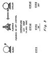
- Figure 3 shows the dynamic display initially.
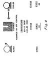
- Figure 4 shows the display after the alarm/action (logical) group BOCA becomes true and the new display "Simulate” is invoked.
- the furnace is shown in alarm.
- the logical group also turned on the fan to cool down the furnace. As the fan cools the furnace, it will cause the temperature to approach the low warning state. When this occurs, the fan is turned off as a result of the logical group BOCA1 becoming true.
- the simple example just described demonstrates the basic operation and principles of a preferred embodiment of the subject invention.
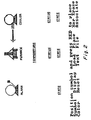
- the flow chart shown in Figure 5 illustrates the process. Briefly summarizing, the system performs the function of monitoring and comparing values to limits, changes of states, elapsed time and combinations of these.
- the limits consist of user defined low alarm limits, low warning limits, rate of change limit, high alarm limit and high warning limit.
- the states consist of a "digital in” or "digital out” being in the logical one or zero state.
- Timer variables are provided to allow the user to define strategies based on time. Monitoring consists of acquiring the value of each variable on a user defined frequency and a system defined phase.
- the values are compared to limits or states, and a bit mask is set to note the current state of each variable in the system. Users will define limits and the frequency at which the variable is scanned during variable definition.
- Alarm definition is accomplished by linking up to 16 variables and a state or limit for each variable to a specific action/alarm name. Also linked to this name is the action to be taken when the states are true.
- the actions (alarms) can include any or all of the following:
- the logical grouping function of the invention is performed by first employing a display manager to retrieve data from the user.
- the display manager is not a part of the invention and could be any commercially available product similar to the SPF or CICS programs available from IBM.
- the data items input by the user include the following:
- the old alarm/action file's first record is acquired.
- the first two bytes of the record contain the number of records in the file.
- the second two bytes contain the last entry number used in the file.
- Total records is set equal to the number of records in the file, and Oldentry is set equal to the last entry number used.
- the data items are collected interactively by the user filling in the blanks of successive screens.
- the first screen of data is a prompt for the alarm/action name.
- the user enters a name consisting of a 8 alpha-numeric characters.
- the alarm/action file is searched for the entry. If the entry exists in the file, the items previously entered are retained as the current items to be edited. If the entry does not exist, the current items are blanked out and the name is used as a new entry.
- One function key is a dedicated rotate key. This key enables the user to display each alarm/action name in the prompt field one-at-a-time.
- the second screen is displayed with the contents of the current items. If the current items are blanks, then all data fields on the second screen are blank. The user must enter at least one variable name and choose the state or alarm limit of interest.
- the user may choose up to 14 other variables and their states or limits.
- the way the user enters a variable state combination is to enter the variable name or use the rotate key to rotate through all the valid variable names from the variable file.
- the 5 limits will appear under their categories or the two digital states will appear.
- the user can use the tab key to select a state, differentiation of the selected state or limit is achieved by reverse-video display of the selected limit or state.
- the state or limit of interest is selected, the user presses the enter key to signify choice.
- the entry number in the variable file for the variable selected is then ORed with the state or limit to form the logic entry for the alarm/action entry.
- the masks are as follows: Hex 8000 for High Alarm, Hex 4000 for High Warning, Hex 2000 for rate of change, Hex 8000 for digital status of on or timer elapsed, and Hex 4000 for digital status off or timer reset.
- the user When the user has completed his/her selection of the variables and their states, the user is then prompted to save the entries.
- the user can press function keys F2 or F8 to save the entries in a memory resident data base.
- the third screen of information is presented to the user.
- the third screen first prompts the user for a message to appear on the user defined screen and a message to appear on the bottom of the screen. If entered, these are stored in the memory resident data base; otherwise, a null entry is stored. The next entry is for a new screen to appear. All new screens must have a unique file type of ".ddt"; therefore, checking can be done to assure the user's entry is a valid new screen. If a screen's name is entered, the name is stored in the memory resident data base; otherwise, a null entry is saved. The next entry is the event history entry. This field calls for a "Y" or "N" entry. A default of "N" is assumed. This entry determines whether a record is written to the event history file whenever the logical group becomes true.
- the next entry is the alarmable function entry. It is also a "Y” or a "N” field. A default of "N” is assumed. This entry determines whether alarm records should be written to the alarm history file for the logical group. If a "Y” is entered, a record will be written whenever the logical group becomes true, is acknowledged, and becomes not true. The next entry is the audible alarm field. A “1" in this field signifies a single beep whenever the logical group is true, a "2" signifies a continual beeping until acknowledgement of the alarm, and a blank entry signifies no beep is to occur. The final two entries are timer variable names.
- the reset timer allows a timer variable to be reset on the occurrence of a logical group becoming true.
- the start time allows a timer variable to be started on the basis of a logical group becoming true. Both of these entries are checked by searching the variable file to determine if the name entered is an actual timer variable. After all the entries have been filled out properly, the user is prompted to save the entries. This is accomplished by pressing either of the function keys F2 or F8. When the user presses F2 or F8, the next screen is presented.
- the fourth screen of data presents the user with 8 blank variable name slots.
- the user is prompted to "fill-in-the-blanks with "digital outs". Up to eight "digital outs" and their states may be specified for control action in the event of the logical group becoming true.
- the variable file is searched to verify the name being a "digital out”. If it is, the zero state name and the one state name are obtained from the name file through pointers contained in the variable file record for the "digital out”.
- the state names are then displayed on the screen under their titles. The user can tab between the two entries to select the state of his/her choice.
- variable file entry number is ORed with Hex 4000. If on the other hand the one state is selected, the variable file entry is ORed with Hex 8000. The modified entry number is the stored in the memory resident data base. This process continues until the user presses function key F2 to save the alarm/action entry.
- the memory resident data base When the function key F2 is pressed on the final page, the memory resident data base is transformed into a record to be entered into the alarm/action file.
- the memory resident data base consists of an 8 byte alarm/action name, a 32 byte array containing the logic entries, two 39 byte message fields, an 8 byte screen field, a two byte'event history field, a two byte alarm field, a two byte audible alarm field, a two byte reset timer field, a two byte start timer field, and an 18 byte "digital out" array. If the user entries are an update of an already existing logical group, the entries go into the existing record in the alarm/action file.
- a search of the alarm/action file is made to find a free record (designated by a-1 in the entry field). Oldentry is then incremented and the empty records entry number is set equal to Oldentry. Each logic entry is then entered into the record. Then the user defined screen message is entered into the message file and a pointer to the message file record is saved in the alarm/action file. If no message was entered by the user, a "-1" is entered as the pointer value. The Bottom of the screen message is handled the same way. The full screen name is entered into the name file and a pointer to the name record is entered into the alarm/action file.
- the alarm/action file is cleaned-up. This process consists of searching the alarm/action file for any entry numbers not equal to ''1'' and putting the entries at the front of the file starting with the second record. Then, the number of records is entered in the first two bytes of the first entry, and the last entry number used is entered in the second two bytes of the first record.
- Type 1 (Analog In) has a format as given below:
- Type 2, 3 and 4 Digital In, Digital Out and Timer have a format as given below:
- the message file has a format as given below:
- the name file has a format as given below:
- the engineering units file has a format as below:
- Event table file (event.tab):
- This file contains the background bit pattern making up the graphic screen image of the process. 10) Symbol Tables file (NAME.SYM where NAME is the symbol table name):
- This file contains the graphic images of the symbols used to create a screen.
- Each symbol table has a similar format as follows:
- This file contains the schematic names and a description for each schematic. Each record has:
Description
- The present invention is in the field of monitoring and alarm systems, and more particularly, the invention is directed to such a system which can be customized by the end user to provide monitoring and alarm function for a variety of applications.
- Monitoring and alarm systems are required for a wide variety of applications ranging from simple mechanisms to rather complex processes. An example of a simple mechanism requiring a monitoring and alarm system would be a home heating system, and an example of a complex process also requiring a monitoring and alarm system would be a petroleum cracking plant. In the past, the monitoring and alarm systems that have been provided for such diverse applications have been quite different reflecting the differing complexity of the applications. For example, a heating system might be equipped with a temperature sensor to monitor the plenum temperature of the furnace and a simple audio or visual alarm to provide an indication when a safe temperature is exceeded. In contrast, the petroleum cracking plant incorporates many processes that are mutually interdependent. Not only are temperatures at various points in the plant monitored, but flow rates, chemical constituents and various other variables are monitored. Some of the monitored variables may have single value set points or limits which, if exceeded, would constitute an alarm condition. More often, however, the variables being monitored are interdependent meaning that an alarm condition is not indicated unless a certain combination of variable values is detected.
- The monitoring and alarm systems which have been developed for very complex applications are characterized by central processing units (CPU) connected to receive inputs from a plurality of sensors and to generate the appropriate alarms or other indications that may be required for the particular application. The CPU is programmed and otherwise adapted for use in the specific environment. Since each installation is, in effect, a special purpose design, the monitoring and alarm systems for such complex applications are very expensive; however, the expense is justified by the relatively great cost of the application itself. There are on the other hand many applications which would be greatly improved by more sophisticated monitoring and alarm systems but for which the expense of such systems as presently designed cannot be justified.
- In DE-A-2941 666 is disclosed a monitoring and alarm system comprising a central processing unit and a plurality of remotely located transponder units each communicating with the central unit to provide a full array of alarm and status signals. The transponder units are capable, under the control of an operator-controlled keyboard, of altering a number of system parameters which relate to the area where the transponder is located, such as opening and closing time of a store, passwords etc. However, the data entry operations require trained operators because these operations are not interactive, and in addition the system does not allow the operator to define all variables and all alarm actions.
- It is therefore an object of the present invention to provide a monitoring and alarm system of general purpose design which can be customized for use with many different applications to provide sophisticated alarming and control functions based on logical relationships among several sensed variables.
- It is another object of the subject invention to provide a monitoring and alarm system for custom applications that uses a CPU to not only monitor a plurality of variables and test their values against predetermined values, but also allow the end user to easily and readily adapt the system to a specific environment.
- It is a further object of the invention to provide a CPU based monitoring and alarm system of general purpose design in which the end user can input the desired values and logical relationships for several sensed variables and the alarms and/or control actions to be provided for a particular application.
- The foregoing and other objects of the invention are attained in a preferred embodiment by using a microcomputer as the CPU for the monitoring and alarm system. The microcomputer may be one of the popular personal or small business computers now on the market, but in the preferred embodiment, the microcomputer is the IBM Personal Computer. This microcomputer is connected to receive a plurality of inputs from various sensors, the variety and type of which are the choice of the end user depending on the specific application to which the monitoring and alarm system is to be connected. The microcomputer may also be connected to suitable audio and/or visual alarms or instead of, or in addition, to, may be programmed to employ the built-in speaker and/or the display monitor to provide the required alarm functions.
- The microcomputer is programmed to provide the end user with a plurality of screens or menus to first allow the user to input data that defines the input variables. This is done by associating the variable names with the hardware addresses of the several sensors that provide inputs to the microcomputer. Next the end user is prompted to input data that determines the states, limits and logical groupings of the several variables being monitored. This allows a very flexible arrangement that allows the end user to customize a general purpose design to a specific end use environment. Moreover, it is possible to easily modify the system by adding or removing sensors or by changing the states, limits and logical groupings of the variables being monitored without expensive modifications or reprogramming. When a logical group has been defined, then on the basis of all the conditions defined by the logical group being true, the microcomputer is programmed to perform the alarm and control functions which are also determined by the end user by the input of data in response to screen prompts.
- More generally speaking the present invention relates to a monitoring and alarm system for a computer controlled equipment comprising:
- - a central processing unit,
- - a plurality of sensors associated with given components of said equipment, polled by said central processing unit to provide output signals representative of the states of said components,
- - a plurality of command lines for issuing alarm signals and/or control signals to change the states of at least a part of said components, said output signals, said alarm signals and said control signals being referred to as "variables", characterized in that it further comprises
- - display means for displaying prompts requesting the user to define those variables of the equipment to be monitored and controlled, and to group a plurality of said variables and the states and/or limits of each variable in a group,
- - data entry means to allow the user to enter the data required by said prompts, and
- - alarm means controlled by said central processing unit in response to all the conditions defined by the states and limits of variables entered by the user in a group being true, whereby said system may be customized by a user for any specific computer controlled equipment.
- The objects of the invention as well as other aspects and advantages thereof will be better understood from the following detailed description of the invention with reference to the accompanying drawings, in which:
- Figure 1 is a block diagram of a simple furnace control system used as a pedagogical example of the operation of the invention;
- Figure 2 is an illustration of a schematic display for the pedagogical example of Figure 1;
- Figure 3 is an illustration of the initial schematic display showing temperature and state conditions of the furnace and state condition of the cooler or fan for the pedagogical example of Figure 1;
- Figure 4 is an illustration of the schematic display showing the furnace in an alarm condition as well as the temperature and state condition of the furnace and the state condition of the cooler or fan for the pedagogical example of Figure 1; and
- Figure 5 is a flow chart summarizing the process of making the logical groupings according to the invention.
- Referring now to the drawings and more particularly to Figure 1, there is shown a simple furnace control system which illustrates the basic principal of the subject invention. A
host computer 10 is the principal monitoring and control element. In the preferred embodiment, thehost computer 10 is an IBM Personal Computer or similar microcomputer, and as will become clear in the following description, thehost computer 10 is programmed to permit the user to customize the monitoring and control functions of the computer for the specific application and environment. In this simple example, afurnace burner 12 is operational to generate heat, and athermocouple 14 is responsive to the heat generated and produces an electrical signal which is amplified byamplifier 16. The output ofamplifier 16 is connected to one input of thehost computer 10 by means of an appropriate analog-to-digital interface 18. The signal from theamplifier 16 is referred to as an "analog in" signal because the signal may vary over a range of values. For example, the "analog in" signal fromamplifier 16 may represent thermocouple temperatures in the range of -85° to 50° Celsius (-120° to +120° Fahrenheit). In contrast a "digital in" signal would have either an on or off value. Similarly, a "digital out" signal may be turned on or off by a software transaction initiated at thehost computer 10. Thus, a "digital in" or a "digital out" signal represents a single bit of information which may be in either the 0 or the 1 state. In Figure 1, there are three "digital out" signals from thehost computer 10. One is supplied to avalve 20 that is operative to turn theburner 12 either on or off. A second is supplied to thefan 22 to turn it either on or off. The third is supplied to the -alarm 24 to activate it. - The first operation that must be performed by the user of the subject invention is to define the variables of the system that is being monitored and controlled. This process may be characterized as creating a strategy of control and is accomplished by associating variable names with sensor hardware addresses. This is facilitated with a series of screens or menus which are generated by any well known display manager utility. The first of these is illustrated below:

- In the screen illustrated above, the brackets indicate the locations of user inputs which are typically made by means of a keyboard that is part of the
host computer 10. This convention is common to many well known programs requiring data input from the user. In this specific screen, a "digital out" is defined. The variable's hardware address is cluster 0, port 1 and bit 1. Note that the sensor type is specified as DO meaning that it is a "digital out". Obviously, AI stands for analog in and DI stands for "digital in". Not previously mentioned, however, is TI which stands for "Timer". This is another type of input to the host computer that allows the user flexibility in deciding whether a delay should be built into the alarm. When the variable defined by the illustrated screen is in the zero state, the message "OFF" will appear or any screen for which this variable is defined. This particular variable is assigned the eight character name "FURNONOF". The name was chosen to reflect the ability to turn the furnace on or off. - The second variable defined is "COOLONOF". As the name suggests, this variable is a "digital out" employed to turn the
fan 22 on and off. The definition for it is found in the screen illustrated below:
- The variable "COOLONOF" has a hardware address of cluster number 0, port 1 and bit 0. It is also a "digital out" as indicated by the sensor type DO.
- The third variable to be defined is "SETALARM". As the name suggests, this variable has the purpose of turning the
alarm 24 on and off. It is also a digital out, and it is defined by the screen shown below:
- The fourth variable defined is "FURNTEMP". It represents the analog in coming from the
thermocouple 14. The limits associated with "FURNTEMP" and its addressing information are contained in the screen illustrated below:
- The fifth variable defined is "FURN1". This variable represents an "analog in" whose value is obtained by a conversion algorithm defined at file definition time. The conversion information is displayed in the <Zero in Eng. Unit> field and the <Full Scale in Eng. Unit> field. The values in this example are -17.777 and 37.7777. They facilitate the conversion of a value 0-100% full scale to a value in engineering units. In this specific case, a value in degrees Fahrenheit is converted to degrees Celsius. The addressing and limit information for the variable are shown in the screen below:

- The next step in defining the control strategy employed is to create the logical groupings of the defined variables. The screen shown below shows the name of the alarm/action definition (logical group) which, for this exqmple, is "BOCA":

- The screen shown below shows the single variable "FURNTEMP" and the state of interest for the control logic:

- As shown in this screen, the state is in the high warning condition at 77° Celsius (170°F). When "FURNTEMP" is in high warning, the alarm and action definitions outlined in the following two screens will occur:


- In the first of the above two screens, the first item is the <Message to Appear on User Defined Screen>. The message appears when the logical group becomes true and remains until the logical group becomes not true. The next item is the <Message to Appear on the Bottom of the Screen>. This message appears on the bottom of the display when the logical group becomes true. The message is also logged to the printer and time and date stamped. The next item defines the new display to appear when the logical group becomes true. The next item says that no record is to be written to the event history file. The next item says that the logical group is an alarmable function. That implies that any alarm area on a dynamic display that is linked to this logical group will blink red, for example, when the logical group becomes true. It also implies that a record will be written to the alarm file when the logical group becomes true. It also implies that a record will be written to the alarm file when the logical group becomes true, when the alarm is responded to, and when the logical group is no longer true. The next entry is the audible alarm entry. By putting a 1 in the blank, a short audible alarm will occur when the logical group becomes true. The next two entries are blank because no timer is involved in this strategy. In the next screen, the digital outs and their states are defined for this logical group. When the logical group becomes true, these digital outs will be set if they are not already in the specified states. The purpose of this logical group is to set an alarm on the screen and turn on the fan whenever the furnace gets too warm.
- Another alarm/action (logical) group is defined to turn on the furnace initially and turn off the fan when the furnace gets too cold. Its name is BOCA1 in this example. In the screen shown below, the name of the alarm/action (logical) group is inserted by the user:

- The next screen shows the single variable FURNTEMP and the state of interest for the control logic, which in this case is the low warning condition. This screen is shown below:

- When FURNTEMP is in low warning, the alarm and action definitions shown in the next two screens will appear. In the first of these screens shown below, the first item is again the <Message to Appear on User Defined Screen>. The message appears when the logical group becomes not true. The next item is the <Message to Appear at the Bottom of the Screen>. This message appears on the bottom of the display when the logical group becomes true and is also logged to the printer and time and date stamped. The next item defines the new display to appear when the logical group becomes true and so forth as before:

- In the next screen, the "digital outs" and their states are defined for this logical group:

- As part of the customization process, the user generates a schematic display of the process to which the monitoring and alarm system is being applied. The preferred method of generating the schematic display is disclosed in European application No. 84104621.2. Text is added to this display according to the technique described in that application. For the specific example being described, the schematic display is quite simple as shown in Figure 2. The symbol labeled "Alarm" corresponds to alarm 24 shown in Figure 1. Similarly, the symbol labeled "Furnace" corresponds to the
furnace including burner 12, and the symbol labeled "Cooler" corresponds to thefan 22. The steps involved in creating the schematic display of Figure 2 are as follows: - 1) Place all the primary symbols on the screen in the locations desired.
- 2) Position the text strings in the appropriate locations.
- 3) Underline any locations of primary importance.
- 4) Link all alarm/action definitions and variables with the areas designated for them on the screen.
- 5) File the schematic away under a name of the user's choice. In the specific example being described, the name chosen was "Simulate".
- 6) Press function key F3 to signify the completion of the schematic generation process.
- The screen shown below is an example of a screen that allows the user to select the desired dynamic display:

- Assuming that "Whole" is selected, Figure 3 shows the dynamic display initially. Figure 4 shows the display after the alarm/action (logical) group BOCA becomes true and the new display "Simulate" is invoked. In Figure 4, the furnace is shown in alarm. The logical group also turned on the fan to cool down the furnace. As the fan cools the furnace, it will cause the temperature to approach the low warning state. When this occurs, the fan is turned off as a result of the logical group BOCA1 becoming true.
- The simple example just described demonstrates the basic operation and principles of a preferred embodiment of the subject invention. The flow chart shown in Figure 5 illustrates the process. Briefly summarizing, the system performs the function of monitoring and comparing values to limits, changes of states, elapsed time and combinations of these. The limits consist of user defined low alarm limits, low warning limits, rate of change limit, high alarm limit and high warning limit. The states consist of a "digital in" or "digital out" being in the logical one or zero state. Timer variables are provided to allow the user to define strategies based on time. Monitoring consists of acquiring the value of each variable on a user defined frequency and a system defined phase. The values are compared to limits or states, and a bit mask is set to note the current state of each variable in the system. Users will define limits and the frequency at which the variable is scanned during variable definition. Alarm definition is accomplished by linking up to 16 variables and a state or limit for each variable to a specific action/alarm name. Also linked to this name is the action to be taken when the states are true. The actions (alarms) can include any or all of the following:
- 1) Setting up to 8 "digital outs" to a user defined value.
- 2) Blinking an area on the screen in a user defined color.
- 3) Replacing the current display with a user defined display.
- 4) Putting a message on the user's display.
- 5) Displaying an alarm message.
- 6) Writing a record to the event file.
- 7) Sounding the horn on the Personal Computer.
- 8) Resetting a timer variable.
- 9) Starting a timer variable.
- The logical grouping function of the invention is performed by first employing a display manager to retrieve data from the user. The display manager is not a part of the invention and could be any commercially available product similar to the SPF or CICS programs available from IBM. The data items input by the user include the following:
- 1) At least one and up to 15 variables and their states.
- 2) A message to display on a schematic.
- 3) An alarm message.
- 4) Another display name.
- 5) Whether a record should be written to the event history file.
- 6) Whether a record should be written to the alarm history file.
- 7) Whether an audible alarm should be sounded for a short time, until acknowledged, or never.
- 8) Whether a timer variable should be reset.
- 9) Whether a timer variable should be started.
- 10) Up to 8 "digital outs".
- When logical groupings is initially invoked, the old alarm/action file's first record is acquired. The first two bytes of the record contain the number of records in the file. The second two bytes contain the last entry number used in the file. Total records is set equal to the number of records in the file, and Oldentry is set equal to the last entry number used.
- The data items are collected interactively by the user filling in the blanks of successive screens. The first screen of data is a prompt for the alarm/action name. The user enters a name consisting of a 8 alpha-numeric characters. The alarm/action file is searched for the entry. If the entry exists in the file, the items previously entered are retained as the current items to be edited. If the entry does not exist, the current items are blanked out and the name is used as a new entry. One function key is a dedicated rotate key. This key enables the user to display each alarm/action name in the prompt field one-at-a-time.
- After a name is entered, the second screen is displayed with the contents of the current items. If the current items are blanks, then all data fields on the second screen are blank. The user must enter at least one variable name and choose the state or alarm limit of interest.
- Additionally, the user may choose up to 14 other variables and their states or limits. The way the user enters a variable state combination is to enter the variable name or use the rotate key to rotate through all the valid variable names from the variable file. When a valid variable is entered, the 5 limits will appear under their categories or the two digital states will appear. The user can use the tab key to select a state, differentiation of the selected state or limit is achieved by reverse-video display of the selected limit or state. When the state or limit of interest is selected, the user presses the enter key to signify choice. The entry number in the variable file for the variable selected is then ORed with the state or limit to form the logic entry for the alarm/action entry. The masks are as follows: Hex 8000 for High Alarm, Hex 4000 for High Warning, Hex 2000 for rate of change, Hex 8000 for digital status of on or timer elapsed, and Hex 4000 for digital status off or timer reset.
- When the user has completed his/her selection of the variables and their states, the user is then prompted to save the entries. The user can press function keys F2 or F8 to save the entries in a memory resident data base. At that point, the third screen of information is presented to the user.
- The third screen first prompts the user for a message to appear on the user defined screen and a message to appear on the bottom of the screen. If entered, these are stored in the memory resident data base; otherwise, a null entry is stored. The next entry is for a new screen to appear. All new screens must have a unique file type of ".ddt"; therefore, checking can be done to assure the user's entry is a valid new screen. If a screen's name is entered, the name is stored in the memory resident data base; otherwise, a null entry is saved. The next entry is the event history entry. This field calls for a "Y" or "N" entry. A default of "N" is assumed. This entry determines whether a record is written to the event history file whenever the logical group becomes true. The next entry is the alarmable function entry. It is also a "Y" or a "N" field. A default of "N" is assumed. This entry determines whether alarm records should be written to the alarm history file for the logical group. If a "Y" is entered, a record will be written whenever the logical group becomes true, is acknowledged, and becomes not true. The next entry is the audible alarm field. A "1" in this field signifies a single beep whenever the logical group is true, a "2" signifies a continual beeping until acknowledgement of the alarm, and a blank entry signifies no beep is to occur. The final two entries are timer variable names. The reset timer allows a timer variable to be reset on the occurrence of a logical group becoming true. The start time allows a timer variable to be started on the basis of a logical group becoming true. Both of these entries are checked by searching the variable file to determine if the name entered is an actual timer variable. After all the entries have been filled out properly, the user is prompted to save the entries. This is accomplished by pressing either of the function keys F2 or F8. When the user presses F2 or F8, the next screen is presented.
- The fourth screen of data presents the user with 8 blank variable name slots. The user is prompted to "fill-in-the-blanks with "digital outs". Up to eight "digital outs" and their states may be specified for control action in the event of the logical group becoming true. When a user enters a variable name, the variable file is searched to verify the name being a "digital out". If it is, the zero state name and the one state name are obtained from the name file through pointers contained in the variable file record for the "digital out". The state names are then displayed on the screen under their titles. The user can tab between the two entries to select the state of his/her choice. After the desired choice is displayed in reverse-video, the user can press the enter key to signify selection and if the zero state name is selected, the variable file entry number is ORed with Hex 4000. If on the other hand the one state is selected, the variable file entry is ORed with Hex 8000. The modified entry number is the stored in the memory resident data base. This process continues until the user presses function key F2 to save the alarm/action entry.
- When the function key F2 is pressed on the final page, the memory resident data base is transformed into a record to be entered into the alarm/action file. The memory resident data base consists of an 8 byte alarm/action name, a 32 byte array containing the logic entries, two 39 byte message fields, an 8 byte screen field, a two byte'event history field, a two byte alarm field, a two byte audible alarm field, a two byte reset timer field, a two byte start timer field, and an 18 byte "digital out" array. If the user entries are an update of an already existing logical group, the entries go into the existing record in the alarm/action file. If not, a search of the alarm/action file is made to find a free record (designated by a-1 in the entry field). Oldentry is then incremented and the empty records entry number is set equal to Oldentry. Each logic entry is then entered into the record. Then the user defined screen message is entered into the message file and a pointer to the message file record is saved in the alarm/action file. If no message was entered by the user, a "-1" is entered as the pointer value. The Bottom of the screen message is handled the same way. The full screen name is entered into the name file and a pointer to the name record is entered into the alarm/action file. The entries for event history data field, alarm field and the audible alarm field are put into the record, then the reset timer entry and the start timer, and finally the 8 "digital out" entries are inserted into the record. Then, the record is written to the alarm/action file, the memory data base is initialized and the first screen is presented to the user.
- When the user selects the function key F3 to end the program, the alarm/action file is cleaned-up. This process consists of searching the alarm/action file for any entry numbers not equal to ''1'' and putting the entries at the front of the file starting with the second record. Then, the number of records is entered in the first two bytes of the first entry, and the last entry number used is entered in the second two bytes of the first record.
- The following is a description of the files used in the preferred embodiment of the invention:
-
- a) The first record of the variable file has two entries. The first two bytes is the number of records contained in the file. The second two bytes contain the largest entry number used.
- b) Each record after the first record have one of two formats. Differentiation of format is accomplished by the type entry which occurs in the same location of each format.
- Type 1 (Analog In) has a format as given below:

- Type 2, 3 and 4 (Digital In, Digital Out and Timer) have a format as given below:

-
- a) The first record of the Alarm/Action file has two entries. The first two bytes is the number of records contained in the file. The second two bytes contain the largest entry number used.
- b) Each record after the first record has the following:


- The message file has a format as given below:

- The name file has a format as given below:

- The engineering units file has a format as below:

-
- a) The first record of the Event table file has one entry. The first two bytes is the number of the last record written.
- b) Each record after the first record has:

-
- a) The first record of the Alarm table file has one entry. The first two bytes is the number of the last record written.
- b) Each record after the first record has:

-
- a) The first record of the Dynamic Display Table file has one entry. The first two bytes is the number of records in the file.
- b) Each record after the first record has:

- This file contains the background bit pattern making up the graphic screen image of the process. 10) Symbol Tables file (NAME.SYM where NAME is the symbol table name):
- This file contains the graphic images of the symbols used to create a screen. Each symbol table has a similar format as follows:
- 1) The first two bytes are used for the number of symbols.
- 2) The next 2$n bytes (where n=number of symbofs)-each of these locations contains the offset in bytes from the start of the symbol buffer area where the symbol is contained.
- 3) The next ??? bytes is the symbol buffer area. The symbols are all stored adjacent each other in screen-ready format. Each symbol has four bytes of x, y information and INT ((2*X+7)/8)*Y bytes of bit information.
- This file contains the schematic names and a description for each schematic. Each record has:

Claims (7)
Applications Claiming Priority (2)
| Application Number | Priority Date | Filing Date | Title |
|---|---|---|---|
| US531650 | 1983-09-13 | ||
| US06/531,650 US4644478A (en) | 1983-09-13 | 1983-09-13 | Monitoring and alarm system for custom applications |
Publications (2)
| Publication Number | Publication Date |
|---|---|
| EP0141132A1 EP0141132A1 (en) | 1985-05-15 |
| EP0141132B1 true EP0141132B1 (en) | 1988-03-30 |
Family
ID=24118486
Family Applications (1)
| Application Number | Title | Priority Date | Filing Date |
|---|---|---|---|
| EP84110265A Expired EP0141132B1 (en) | 1983-09-13 | 1984-08-29 | Monitoring and alarm system for custom applications |
Country Status (4)
| Country | Link |
|---|---|
| US (1) | US4644478A (en) |
| EP (1) | EP0141132B1 (en) |
| JP (1) | JPS6084047A (en) |
| DE (1) | DE3470239D1 (en) |
Families Citing this family (72)
| Publication number | Priority date | Publication date | Assignee | Title |
|---|---|---|---|---|
| US4703325A (en) * | 1984-10-22 | 1987-10-27 | Carrier Corp. | Remote subsystem |
| DE3672377D1 (en) * | 1985-04-24 | 1990-08-09 | Mitsubishi Electric Corp | MONITORING DATA PROCESSING SYSTEM FOR A COMPONENT ELECTRICITY POWER PLANT. |
| DE3687222T2 (en) * | 1985-09-05 | 1993-07-01 | Omron Tateisi Electronics Co | CIRCUIT FOR A TRANSMITTER. |
| US4803039A (en) * | 1986-02-03 | 1989-02-07 | Westinghouse Electric Corp. | On line interactive monitoring of the execution of process operating procedures |
| US4811247A (en) * | 1986-05-20 | 1989-03-07 | Apco Technical Services, Inc. | Random selection system |
| US4831559A (en) * | 1986-07-25 | 1989-05-16 | Phillips Petroleum Company | Method and apparatus for periodically determining the flash point of a flammable liquid |
| EP0264856B1 (en) * | 1986-10-20 | 1994-03-09 | Matsushita Electric Industrial Co., Ltd. | Gas shutoff apparatus |
| US4897798A (en) * | 1986-12-08 | 1990-01-30 | American Telephone And Telegraph Company | Adaptive environment control system |
| US4858152A (en) * | 1987-01-23 | 1989-08-15 | International Business Machines Corp. | Operator access to monitoring applications |
| US5062147A (en) * | 1987-04-27 | 1991-10-29 | Votek Systems Inc. | User programmable computer monitoring system |
| US4885694A (en) * | 1987-04-29 | 1989-12-05 | Honeywell Inc. | Automated building control design system |
| IE872812L (en) * | 1987-10-20 | 1989-04-20 | Winsju Ltd | Control unit for an alarm system |
| US4977527A (en) * | 1988-04-14 | 1990-12-11 | Fike Corporation | Threshold compensation and calibration in distributed environmental detection system for fire detection and suppression |
| US5208745A (en) * | 1988-07-25 | 1993-05-04 | Electric Power Research Institute | Multimedia interface and method for computer system |
| US4931950A (en) * | 1988-07-25 | 1990-06-05 | Electric Power Research Institute | Multimedia interface and method for computer system |
| DE69026014T2 (en) * | 1989-01-25 | 1996-10-17 | Nohmi Bosai Ltd | FIRE ALARM SYSTEM |
| USRE38640E1 (en) * | 1989-02-23 | 2004-10-26 | Fisher-Rosemount Systems, Inc. | Process control terminal |
| US5243511A (en) * | 1989-06-30 | 1993-09-07 | Icom, Inc. | Method and apparatus for block move re-addressing in ladder logic programs |
| US5267145A (en) * | 1989-06-30 | 1993-11-30 | Icom, Inc. | Method and apparatus for program navigation and editing for ladder logic programs by determining which instructions reference a selected data element address |
| US5127099A (en) * | 1989-06-30 | 1992-06-30 | Icom, Inc. | Method and apparatus for securing access to a ladder logic programming and monitoring system |
| US5276811A (en) * | 1989-06-30 | 1994-01-04 | Icom, Inc. | Method for emulating programmable logic controller by exchanging information between debug program which emulates I/O devices and ladder logic program |
| US5349518A (en) * | 1989-06-30 | 1994-09-20 | Icom, Inc. | Method and apparatus for symbolic ladder logic programming with automatic attachment of addresses |
| US4991076A (en) * | 1989-06-30 | 1991-02-05 | Icom Inc. | Method and apparatus for creating custom displays for monitoring ladder logic programs |
| US5121344A (en) * | 1989-07-03 | 1992-06-09 | The United States Of America As Represented By The Secretary Of The Interior | Method of locating underground mines fires |
| US5289381A (en) * | 1989-12-04 | 1994-02-22 | Maschinenfabrik Rieter Ag | Method and apparatus for continuously determining the fineness of fibers in slivers |
| US6009284A (en) * | 1989-12-13 | 1999-12-28 | The Weinberger Group, L.L.C. | System and method for controlling image processing devices from a remote location |
| JP2947840B2 (en) * | 1989-12-22 | 1999-09-13 | 株式会社日立製作所 | Plant operation monitoring device |
| GB2244360A (en) * | 1990-05-25 | 1991-11-27 | Microsys Consultants Limited | Security systems |
| US5061916A (en) * | 1990-05-29 | 1991-10-29 | Barber-Colman Company | Event driven remote graphical reporting of building automation system parameters |
| US5321829A (en) * | 1990-07-20 | 1994-06-14 | Icom, Inc. | Graphical interfaces for monitoring ladder logic programs |
| US5335339A (en) * | 1990-11-22 | 1994-08-02 | Hitachi, Ltd. | Equipment and method for interactive testing and simulating of a specification of a network system |
| US5392226A (en) * | 1993-06-17 | 1995-02-21 | Icom, Inc. | Computer-implemented method and apparatus for monitoring statistical process control data |
| US5444436A (en) * | 1993-12-29 | 1995-08-22 | Kennison; Ricky R. | Furnace and air conditioner failure alarm apparatus |
| US5726633A (en) * | 1995-09-29 | 1998-03-10 | Pittway Corporation | Apparatus and method for discrimination of fire types |
| US5761069A (en) * | 1995-11-09 | 1998-06-02 | Custom Ultrasonics, Inc. | Integrated system for cleaning medical instruments |
| US10011247B2 (en) | 1996-03-27 | 2018-07-03 | Gtj Ventures, Llc | Control, monitoring and/or security apparatus and method |
| US7253731B2 (en) | 2001-01-23 | 2007-08-07 | Raymond Anthony Joao | Apparatus and method for providing shipment information |
| US10152876B2 (en) | 1996-03-27 | 2018-12-11 | Gtj Ventures, Llc | Control, monitoring, and/or security apparatus and method |
| JP3211663B2 (en) * | 1996-05-20 | 2001-09-25 | 株式会社日立製作所 | Plant operation information display method and plant operation monitoring device |
| US5984502A (en) | 1996-06-14 | 1999-11-16 | The Foxboro Company | Keypad annunciator graphical user interface |
| US6067477A (en) * | 1998-01-15 | 2000-05-23 | Eutech Cybernetics Pte Ltd. | Method and apparatus for the creation of personalized supervisory and control data acquisition systems for the management and integration of real-time enterprise-wide applications and systems |
| US6571140B1 (en) * | 1998-01-15 | 2003-05-27 | Eutech Cybernetics Pte Ltd. | Service-oriented community agent |
| US9075136B1 (en) | 1998-03-04 | 2015-07-07 | Gtj Ventures, Llc | Vehicle operator and/or occupant information apparatus and method |
| EP1115430A4 (en) | 1998-10-01 | 2002-01-02 | Minntech Corp | Endoscope reprocessing and sterilization system |
| US6279097B1 (en) | 1998-11-20 | 2001-08-21 | Allied Telesyn International Corporation | Method and apparatus for adaptive address lookup table generator for networking application |
| US6774786B1 (en) * | 2000-11-07 | 2004-08-10 | Fisher-Rosemount Systems, Inc. | Integrated alarm display in a process control network |
| US8044793B2 (en) * | 2001-03-01 | 2011-10-25 | Fisher-Rosemount Systems, Inc. | Integrated device alerts in a process control system |
| US7206646B2 (en) * | 1999-02-22 | 2007-04-17 | Fisher-Rosemount Systems, Inc. | Method and apparatus for performing a function in a plant using process performance monitoring with process equipment monitoring and control |
| US7346404B2 (en) * | 2001-03-01 | 2008-03-18 | Fisher-Rosemount Systems, Inc. | Data sharing in a process plant |
| US7562135B2 (en) * | 2000-05-23 | 2009-07-14 | Fisher-Rosemount Systems, Inc. | Enhanced fieldbus device alerts in a process control system |
| US6975219B2 (en) * | 2001-03-01 | 2005-12-13 | Fisher-Rosemount Systems, Inc. | Enhanced hart device alerts in a process control system |
| US7113085B2 (en) * | 2000-11-07 | 2006-09-26 | Fisher-Rosemount Systems, Inc. | Enhanced device alarms in a process control system |
| US6721689B2 (en) | 2000-11-29 | 2004-04-13 | Icanon Associates, Inc. | System and method for hosted facilities management |
| JP4160399B2 (en) * | 2001-03-01 | 2008-10-01 | フィッシャー−ローズマウント システムズ, インコーポレイテッド | Creating and displaying indicators in the process plant |
| US7720727B2 (en) * | 2001-03-01 | 2010-05-18 | Fisher-Rosemount Systems, Inc. | Economic calculations in process control system |
| US8073967B2 (en) | 2002-04-15 | 2011-12-06 | Fisher-Rosemount Systems, Inc. | Web services-based communications for use with process control systems |
| US20020191102A1 (en) * | 2001-05-31 | 2002-12-19 | Casio Computer Co., Ltd. | Light emitting device, camera with light emitting device, and image pickup method |
| US10562492B2 (en) | 2002-05-01 | 2020-02-18 | Gtj Ventures, Llc | Control, monitoring and/or security apparatus and method |
| US8005647B2 (en) | 2005-04-08 | 2011-08-23 | Rosemount, Inc. | Method and apparatus for monitoring and performing corrective measures in a process plant using monitoring data with corrective measures data |
| US9201420B2 (en) | 2005-04-08 | 2015-12-01 | Rosemount, Inc. | Method and apparatus for performing a function in a process plant using monitoring data with criticality evaluation data |
| US7272531B2 (en) * | 2005-09-20 | 2007-09-18 | Fisher-Rosemount Systems, Inc. | Aggregation of asset use indices within a process plant |
| US7378942B2 (en) * | 2005-10-27 | 2008-05-27 | Viking Electronics Services, Llc | Method of designing, installing, and operating a fire alarm or security system |
| US8407716B2 (en) * | 2007-05-31 | 2013-03-26 | Fisher-Rosemount Systems, Inc. | Apparatus and methods to access information associated with a process control system |
| US8301676B2 (en) * | 2007-08-23 | 2012-10-30 | Fisher-Rosemount Systems, Inc. | Field device with capability of calculating digital filter coefficients |
| US7702401B2 (en) | 2007-09-05 | 2010-04-20 | Fisher-Rosemount Systems, Inc. | System for preserving and displaying process control data associated with an abnormal situation |
| US8055479B2 (en) | 2007-10-10 | 2011-11-08 | Fisher-Rosemount Systems, Inc. | Simplified algorithm for abnormal situation prevention in load following applications including plugged line diagnostics in a dynamic process |
| US20130083664A1 (en) * | 2010-09-13 | 2013-04-04 | Jeffrey T. Harris | Remote management hardware platform for site monitoring with smart block i/o device |
| US9927788B2 (en) | 2011-05-19 | 2018-03-27 | Fisher-Rosemount Systems, Inc. | Software lockout coordination between a process control system and an asset management system |
| AU2011379005B2 (en) * | 2011-10-11 | 2015-10-08 | Sandvik Mining And Construction Oy | Maintenance of work machines |
| US10546441B2 (en) | 2013-06-04 | 2020-01-28 | Raymond Anthony Joao | Control, monitoring, and/or security, apparatus and method for premises, vehicles, and/or articles |
| US9821738B2 (en) | 2014-06-30 | 2017-11-21 | Raymond Anthony Joao | Battery power management apparatus and method |
| US11760227B2 (en) | 2021-02-15 | 2023-09-19 | Raymond Anthony Joao | Battery power management apparatus and method |
Family Cites Families (9)
| Publication number | Priority date | Publication date | Assignee | Title |
|---|---|---|---|---|
| US2883651A (en) * | 1958-03-05 | 1959-04-21 | Panellit Inc | Variable monitoring system |
| DE2818211A1 (en) * | 1977-09-19 | 1979-03-22 | Fega Werk Ag Schlieren | Fire alarm evaluation device - has computer providing all information concerning nature of fire and alarm transmission to fire station |
| US4212078A (en) * | 1977-12-27 | 1980-07-08 | United Technologies Corporation | Computer controlled facility management system (FMS) |
| US4228424A (en) * | 1978-10-16 | 1980-10-14 | Baker Protective Services, Incorporated | Central station alarm |
| US4460960A (en) * | 1979-02-02 | 1984-07-17 | International Business Machines Corporation | Transaction execution system having keyboard and message customization, improved key function versatility and message segmentation |
| US4296409A (en) * | 1979-03-12 | 1981-10-20 | Dickey-John Corporation | Combine performance monitor |
| JPS5638609A (en) * | 1979-09-05 | 1981-04-13 | Toshiba Corp | Monitoring method for plant |
| GB2083258B (en) * | 1980-09-03 | 1984-07-25 | Nuclear Power Co Ltd | Alarm systems |
| US4432064A (en) * | 1980-10-27 | 1984-02-14 | Halliburton Company | Apparatus for monitoring a plurality of operations |
-
1983
- 1983-09-13 US US06/531,650 patent/US4644478A/en not_active Expired - Lifetime
-
1984
- 1984-08-29 EP EP84110265A patent/EP0141132B1/en not_active Expired
- 1984-08-29 DE DE8484110265T patent/DE3470239D1/en not_active Expired
- 1984-09-05 JP JP59184740A patent/JPS6084047A/en active Granted
Also Published As
| Publication number | Publication date |
|---|---|
| US4644478A (en) | 1987-02-17 |
| JPH0414815B2 (en) | 1992-03-16 |
| EP0141132A1 (en) | 1985-05-15 |
| DE3470239D1 (en) | 1988-05-05 |
| JPS6084047A (en) | 1985-05-13 |
Similar Documents
| Publication | Publication Date | Title |
|---|---|---|
| EP0141132B1 (en) | Monitoring and alarm system for custom applications | |
| US5896138A (en) | Process control with graphical attribute interface | |
| US4588987A (en) | Display system for monitoring and alarm system | |
| AU720822B2 (en) | Analog spectrum display for environmental control | |
| US4001807A (en) | Concurrent overview and detail display system having process control capabilities | |
| US5621905A (en) | Tree form menu display for a data processing system | |
| EP0733964B1 (en) | Elision based presentation of ordered data | |
| JPH02260099A (en) | Process control terminal equipment | |
| US5842198A (en) | Data management system, that enables a user to connect existing data to an external file and a program to process that data | |
| US3927308A (en) | Monitor and results computer system | |
| US6037938A (en) | Method and a device for displaying information about a large number of independent data elements | |
| JPH061481B2 (en) | Data retrieval method | |
| USRE38640E1 (en) | Process control terminal | |
| JP2000347731A (en) | Automatic data collecting device | |
| JP2788236B2 (en) | Plant operation support device | |
| JPH07182214A (en) | Method for displaying list of file and data processor | |
| JP2782245B2 (en) | Inference processing apparatus and method based on input operation information | |
| JP2835081B2 (en) | Process display device | |
| JP2786785B2 (en) | Plant data processing equipment | |
| JP3567291B2 (en) | Information processing apparatus and item data management method | |
| JPH02133822A (en) | Data processor | |
| JPH0767724B2 (en) | Control device of injection molding machine | |
| JPH04227528A (en) | Method for informing action on data processor and data processor | |
| JP2695529B2 (en) | Opposite modem test control method | |
| JPH07319634A (en) | External memory management system |
Legal Events
| Date | Code | Title | Description |
|---|---|---|---|
| PUAI | Public reference made under article 153(3) epc to a published international application that has entered the european phase |
Free format text: ORIGINAL CODE: 0009012 |
|
| 17P | Request for examination filed |
Effective date: 19841123 |
|
| AK | Designated contracting states |
Designated state(s): DE FR GB IT |
|
| 17Q | First examination report despatched |
Effective date: 19860502 |
|
| GRAA | (expected) grant |
Free format text: ORIGINAL CODE: 0009210 |
|
| AK | Designated contracting states |
Kind code of ref document: B1 Designated state(s): DE FR GB IT |
|
| REF | Corresponds to: |
Ref document number: 3470239 Country of ref document: DE Date of ref document: 19880505 |
|
| ET | Fr: translation filed | ||
| ITF | It: translation for a ep patent filed |
Owner name: IBM - DR. ARRABITO MICHELANGELO |
|
| PLBE | No opposition filed within time limit |
Free format text: ORIGINAL CODE: 0009261 |
|
| STAA | Information on the status of an ep patent application or granted ep patent |
Free format text: STATUS: NO OPPOSITION FILED WITHIN TIME LIMIT |
|
| 26N | No opposition filed | ||
| ITTA | It: last paid annual fee | ||
| PGFP | Annual fee paid to national office [announced via postgrant information from national office to epo] |
Ref country code: FR Payment date: 19940725 Year of fee payment: 11 |
|
| PGFP | Annual fee paid to national office [announced via postgrant information from national office to epo] |
Ref country code: DE Payment date: 19940824 Year of fee payment: 11 |
|
| PG25 | Lapsed in a contracting state [announced via postgrant information from national office to epo] |
Ref country code: FR Effective date: 19960430 |
|
| PG25 | Lapsed in a contracting state [announced via postgrant information from national office to epo] |
Ref country code: DE Effective date: 19960501 |
|
| REG | Reference to a national code |
Ref country code: FR Ref legal event code: ST |
|
| REG | Reference to a national code |
Ref country code: GB Ref legal event code: IF02 |
|
| PGFP | Annual fee paid to national office [announced via postgrant information from national office to epo] |
Ref country code: GB Payment date: 20030804 Year of fee payment: 20 |
|
| PG25 | Lapsed in a contracting state [announced via postgrant information from national office to epo] |
Ref country code: GB Free format text: LAPSE BECAUSE OF EXPIRATION OF PROTECTION Effective date: 20040828 |
|
| REG | Reference to a national code |
Ref country code: GB Ref legal event code: PE20 |