EP0142250A2 - Retroreflective sheeting and methods for making same - Google Patents
Retroreflective sheeting and methods for making same Download PDFInfo
- Publication number
- EP0142250A2 EP0142250A2 EP84306392A EP84306392A EP0142250A2 EP 0142250 A2 EP0142250 A2 EP 0142250A2 EP 84306392 A EP84306392 A EP 84306392A EP 84306392 A EP84306392 A EP 84306392A EP 0142250 A2 EP0142250 A2 EP 0142250A2
- Authority
- EP
- European Patent Office
- Prior art keywords
- percent
- construction
- granular material
- proportion
- pattern
- Prior art date
- Legal status (The legal status is an assumption and is not a legal conclusion. Google has not performed a legal analysis and makes no representation as to the accuracy of the status listed.)
- Granted
Links
Images

Classifications
-
- B—PERFORMING OPERATIONS; TRANSPORTING
- B05—SPRAYING OR ATOMISING IN GENERAL; APPLYING FLUENT MATERIALS TO SURFACES, IN GENERAL
- B05D—PROCESSES FOR APPLYING FLUENT MATERIALS TO SURFACES, IN GENERAL
- B05D5/00—Processes for applying liquids or other fluent materials to surfaces to obtain special surface effects, finishes or structures
- B05D5/06—Processes for applying liquids or other fluent materials to surfaces to obtain special surface effects, finishes or structures to obtain multicolour or other optical effects
- B05D5/061—Special surface effect
- B05D5/063—Reflective effect
-
- B—PERFORMING OPERATIONS; TRANSPORTING
- B29—WORKING OF PLASTICS; WORKING OF SUBSTANCES IN A PLASTIC STATE IN GENERAL
- B29D—PRODUCING PARTICULAR ARTICLES FROM PLASTICS OR FROM SUBSTANCES IN A PLASTIC STATE
- B29D11/00—Producing optical elements, e.g. lenses or prisms
- B29D11/00605—Production of reflex reflectors
-
- G—PHYSICS
- G02—OPTICS
- G02B—OPTICAL ELEMENTS, SYSTEMS OR APPARATUS
- G02B5/00—Optical elements other than lenses
- G02B5/12—Reflex reflectors
- G02B5/122—Reflex reflectors cube corner, trihedral or triple reflector type
- G02B5/124—Reflex reflectors cube corner, trihedral or triple reflector type plural reflecting elements forming part of a unitary plate or sheet
Definitions
- Retroreflective sheeting has particular use in making highway signs, street signs and the like, and is now employed extensively.
- the Federal government has recognized two primary types of retroreflective sheeting: glass bead and cube-corner.
- Such approved sheeting materials are found in a specification entitled "FP-79", published by the U.S. Department of Transportion Federal Highway Administration.
- Specification F P -79 presently has been adopted as a purchasing standard by many State Highway Departments, and it sets forth certain minimum specifications which must be met by retroreflective sheeting of the cube-corner type. Included among the specified characteristics are those for reflectivity, color, flexibility of material, and resistance to cracking and weathering.
- Cube-corner type reflector elements generally provide a higher specific intensity at 0.2 * observation angle and 0° entrance angle than do glass bead type reflector elements, but, to applicants' knowledge, no one successfully has furnished a sheeting material which will meet the requirements for the Class IIIB sheeting set forth in the aforementioned F P -79 specification in commercial' quantities. It therefore is a primary object of the present invention to provide a unique sheeting product which will meet such specified criteria and which can be produced in accordance with the novel methods disclosed herein in an economical fashion and in commercial quantities.
- Retroreflectivity is achieved by cube-corner type reflector elements primarily through the principle of total internal reflection. It is well known that any surface contact made by another material with the faces of the cube-corner elements generally has a deleterious effect on the reflectiveness of the reflector element.
- metallizing will provide a grayish or black coloration under certain daylight conditions and may also generally reduce reflectivity under night-time conditions vis-a-vis unmetallized cube-corner type elements.
- the present invention relates generally to methods and apparatus for producing retroreflective sheeting constructions and, more particularly, to methods and apparatus for producing a flexible laminate sheeting construction including an upper thermoplastic sheet, the reverse of which is provided with a repeating, retroreflecting pattern of fine or precise detail, a back coating to protect the formed pattern, and an intermediate layer allowing bonding of the back coating to overlay the formed pattern on the. thermoplastic sheet while preserving and enhancing the retroreflective properties of both the formed pattern and the laminated sheet. More precisely, the present invention is applicable to the production of cube-corner type retroreflective sheeting laminates.
- cube-corner or “trihedral,” or “tetrahedral” are recognized in the art as describing structure or patterns consisting of three mutually perpendicular faces, not limited to any particular size or shape of the faces, or the orientation of the optical axis of the cube-corner element.
- Each of the cube-corner faces can assume a different size and shape relative to the others, depending upon the angular reflective response characteristics desired, and the cube forming techniques employed.
- one advantageous aspect of such sheeting is in the manufacture of highway and street signs, markers and the like, where graphics are printed, painted, silk-screened or otherwise applied to a highly reflective substrate mounted to a flat, stiff, supportive surface.
- Flexible retroreflective sheeting when used as such a substrate, can be stored and shipped while wound onto rolls, and can readily be cut or otherwise formed into the desired shape and size required for a particular application.
- the reflective nature of the sheeting allows such signs, markers, and the like to reflect light from a vehicle's headlights, permitting the item to be read by the driver, without requiring a permanent light source to illuminate the sign or marker.
- Palmquist, et al., 2,407,680 teach the utilization of glass microspheres or beads included as the reflective elements in flexible sheet forms; Tung, et al., in United States Patent No. 4,367,,920, also describes a laminated sheet construction using glass microspheres as the reflective elements.
- a common problem in the construction of reflective laminate sheeting is to find means to bond the lamina firmly together in a way which preserves the required retroreflective qualities of the reflective elements selected for use.
- An example of prior efforts to solve this problem with respect to glass microspheres may be seen in United States Patent No. 3,190,178, issued to McKenzie, wherein a cover sheet or film is secured over exposed glass microspheres by use of die elements which force a portion of the material in which the glass microspheres are embedded into contact with the cover sheet.
- the die elements thus create a grid pattern on the resulting sheeting construction, with each grid forming a separate cell. Within each cell, an air space is maintained between the microspheres and the cover sheet, and incident light traverses the cover sheet and the air space to be retroreflected by the embedded microspheres.
- Holmen, et al. U.S. Patent No. 3,924,929, teach a cube-corner type upper rigid sheet having upstanding walls, or septa, integrally formed as part of the cube pattern.
- the septa extend to form a regular geometric pattern of individual cells, with the septa extending at least as far from the upper sheet as the cube-corner elements.
- a particulate packing may be used to fill each of the cells, and a backing sheet is then attached to the rear of the upper sheet, with the septa serving as the attachement sites.
- Holmen, et al. use relatively large cube-corner elements fashioned as rigid sections bound to a flexible back, and has limited flexibility in use.
- none of the foregoing teach the assembly of molded or embossed cube-corner type retroreflective sheeting into self-adhesive laminates which protect and enhance the reflective properties of the sheeting without requiring the use of dies or of integrally-molded septa or walls included as part of the cube pattern. Further, none of the foregoing permits the material to benefit from encapsulated sections of cube-corner elements while enhancing and meeting the requirements specified in the aforementioned DOT FP-79 Specification.
- thermoplastic sheet or web is provided on its reverse side with a retroreflective cube-corner type pattern.
- a thin layer of a liquid vehicle or solvent containing hydrophobic granular material (such as silica treated with silanes) is deposited on the reverse side of the web, as by screen printing, in a pattern leaving selected sites devoid of granular material.
- the web is then dried to drive off the solvent and, thereafter, a water-based back coating is applied over the granular material pattern, with portions of the back coating being in direct contact with the thermoplastic web at those sites on the web devoid of granular material. Thereafter, the back coating is dried or cured, and a layer of adhesive such as pressure-sensitive or heat-activated adhesive is applied thereto.
- a thin layer of a hydrophobic silica mixture is screened or sprayed onto an embossed reverse surface of a thermoplastic web in a diamond-like pattern, and is thereafter dried.
- a water-based back coating mixture or formulation is next deposited over the silica layer to encapsulate the silica and to contact the thermoplastic sheet where no silica was deposited.
- the back coating then is heat dried and/or cured to form a continuous film.
- a pressure-sensitive or heat-activated adhesive then is applied to the cured backcoating layer, with the adhesive protected by a release sheet which is removed when the laminate is applied to an object.
- the completed laminate is then cut, trimmed, or otherwise shaped for application to supporting surfaces, such as street or highway signs, and graphics or other indicia may thereafter be painted, printed, silk-screened, or otherwise affixed to the uppermost surface of the laminate, thus producing a readily and easily constructed highly retroreflective finished product.
- the numeral 10 indicates generally a segment of cube-corner type retroreflective thermoplastic web used in forming the laminate of the present invention.
- the figures therein depict the rear surface of a portion of flexible retroreflective sheeting 12 fashioned from transparent thermoplastic material in web form which has formed thereon, preferably by embossing, a retroreflective and repeating pattern of cube-corner reflector elements characterized by cube faces 14, 16 and 18.
- sheet 12 is formed from an impact-modified acrylic material having UV inhibitors or absorbers added thereto, and which, prior to embossing, had parallel front and back surfaces and was initially on the order of about 0.006 inches thick.
- the cube-corner pattern formed in an optically precise finely detailled pattern sheeting 12 is formed in a precise, finely-detailed pattern.
- the depth to which the cube-corner pattern is embossed onto sheet 12 may be of the order of 0.00338 inch, (dimension X).
- the cubes formed on sheet 12 may be spaced apart by a distance on the order of about 0.0072 inch, for the depth as shown at X as set forth above.
- the cube pattern shown in Fig. 1 illustrates cubes formed with their optical axes normal to the face of sheet 12, it is to be understood that other versions and patterns may also be utilized as forming the retroreflective web of the laminate of the present invention.
- the numeral 20 indicates 22 generally a roll of retroreflective laminateLmanufactured in accordance with preferred aspects of the present invention to be described hereinbelow.
- laminate 22 is rolled onto a core 24.
- a thermoplastic web 26 having a front or obverse surface 28 and a rear or reverse surface 30 upon which is embossed the cube-corner type retroreflective pattern is illustrated in Fig. 3.
- the thermoplastic web 26 may be on the order of about 6 mils in thickness (0.006 inch).
- thermoplastic web 26 Bonded to the reverse surface 30 of the thermoplastic web 26 is back coating or film 32.
- a hydrophobic granular silica material 34 is interposed between the back coat film 32 and the reverse side 30 in a manner to be described hereinbelow.
- a layer of adhesive 36 is bonded to a release sheet 38 in a presently well-known fashion, and is thereafter bonded to cured back coat film 32 in order to provide a finished laminate 22 which includes a pressure-sensitive or heat-activated adhesive layer 36 applied to sheeting 12 in a manner which preserves the retroreflective qualities and properties of the cube-corner pattern embossed thereon.
- the release sheet 38 is used to protect adhesive layer 36 until it is desired to apply laminate 22 to a given surface.
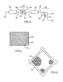
- Fig. 4 shows, in schematic form, a preferred arrangment of equipment and sequence of operations to produce a retroreflective sheeting laminate of the type shown in Fig. 3.
- a substantial portion of the cube-corner pattern either must be hermetically sealed with an air space between the back wall and the cube-corner elements, or the cube-corner elements must be backed in a way which would preserve the retroreflective properties of the formed web while providing sites for firm attachment of an adhesive layer (or other adhesive material). Without such protection, and without such attaching sites, the use of, and effectiveness of a retroreflective embossed web is seriously compromised and curtailed.
- hydrophobic granular materials have been found to afford such protection.
- xylenated glass particles powdered silicone rubber, and silane-treated silica.
- a hydrophobic silica mixture consisting principally of amorphous silica treated with silanes, when used to fill the valleys formed by the embossed pattern, preserves the retroreflective properties of the formed pattern for most practical purposes.
- the point contact of granules with the reverse face of the embossed thermoplastic web acts to preserve the retroreflective properties of the pattern, perhaps by preserving a sufficient air interface with the reverse side of the cube-corner pattern.
- the present invention obtains excellent results even where the silica particles used are significantly smaller than, for example, the particles discussed in prior art patents such as Holmen, et " al., U.S. Patent No. 3,924,929.
- silica offers advantages such as low price, availability, and ease and precision of formulation. It further provides unique color and reflective characteristics to the film which improves the appearance of the film even relative to the glass bead types heretofore commonly used.
- Formation of such septa in a relatively rigid mold pattern manufactured to as fine and precise a degree of detail as that shown in the present invention also may cause problems with respect to stripping the formed thermoplastic web from the forming tool. This may particularly be a problem where the septa or walls extend inwardly into the mold to a distance greater than the depth of the cube-corner pattern.
- a preferred embodiment of the present invention includes the mixing of a hydrophobic silica mixture using hydrophobic silica, organic solvents, and thickeners, and the application of this mixture, while in a liquid form, to the reverse side of the formed thermoplastic web in a desired pattern.
- One advantage of the present process and product is that the pattern can conveniently be changed to effect changes in reflective capability of the film, without changing the tools used in forming the embossed web.
- the partially coated or imprinted thermoplastic web is passed through a drying oven which drives off the solvents used to form the mixture, thereby drying the pattern on the thermoplastic sheet.
- the pattern in which the silica is applied to the thermoplastic web leaves selected portions or sites on the thermoplastic web devoid of silica.
- each runner or path 42 represents an area on the reverse surface of thermoplastic web 26 where no silica has been deposited.
- Each square or" diamond-shaped area 44 represents an area on the surface of thermoplastic web 26 onto which the silica mixture has been deposited.
- the actual percentage of area covered by the silica mixture is determined by the thickness or width of each runner or path 42, and the pattern selected for deposition of the silica, with the cell 44 having an area bounded by the runners, and fully available for the reception and retroreflection of incident light by the embossed retroreflective patterns shown partially at 46.
- thermoplastic web 26 may be drawn directly from an associated forming machine (not herein specifically shown) in a continuous process, or may be drawn from a separate supply reel onto which the embossed web 26 has been wound (not herein specifically shown). If desired, web 26 may be supported by a backing sheet, not herein specifically shown, coextensive with obverse face 28, leaving reverse surface 30 exposed.
- web 26 also includes reference to a laminate formed by web 26 and a backing sheet such as described hereinabove.
- Web 26 is drawn by, for example, powered rollers not herein opecifiacally ohown, to silica mixture application station 48.
- a preferred means and method of applying the silica mixture to web 26 may be accomplished through use of a screen-printing roller 50 which has mounted about the outer periphery thereof, a metal screen formed to provide the shape or pattern to which it is desired to apply the silica mixture.
- the mixture is forced under pressure from the interior of screen-printing drum onto the reverse side 30 of the thermoplastic web 26.
- the web 26 is directed by idler roller 52 to pass between the screen-printing drum 50 and a backing drum 54.
- a preferred form of the apparatus utilized to apply the silica mixture at application station 48 consists of a drum printer manufactured by Stork Brabant BV of Boxmeern, Holland, of the type having a drum with electro-formed mesh screens over which a photo-resist pattern (such as a silk screen) may be mounted, with a screen pattern providing a diamond cell size in the range of from about 0.096 inch to 0.300 inch, and a runner or cell wall thickness of from about 0.010 inch to about 0.050 inch. Variations in the shape of the cells, pattern repeat of the cells, and thickness of the runners may be accomplished by changing the printing screen used on screen-printing drum 50. Also, the constant width of the web may be of various sizes, and the printing screens used will be of a compatible width.
- the silica mixture is made from a hydrophobic silica such as that manufactured by the Pigments Division of Degussa, of Frankfurt, West Germany, under the trade designation Sipernat D10.
- a preferred composition of the mixture includes hydrophobic silica in a mixture containing approximately 98 percent silane-treated silicon dioxide (Sio 2 ); 0.8 percent sodium oxide ( N a 2 0), and 0.8 percent of sulfur trioxide (SO 3 ); a non-polar aliphatic hydrocarbon solvent carrier; a polar solvent; and, where desired or required, a thickening agent.
- One aliphatic non-polar hydrocarbon solvent successfully used is mineral spirits, and a workable mixture has been created through use of an organic alcohol, preferably butanol, as the non-polar solvent material.
- a clay-based thixotropic thickener also may be used in varying amounts to produce a well-defined screen-printed pattern of the silica slurry on the embossed thermoplastic web.
- Another important consideration is the rheology, or flow characteristics of the silica slurry as it is forced through the printing screen.
- the slurry must "relax,” or thin as it is forced through the screen apertures, and thereafter regain sufficient viscosity to retain a well-defined pattern with good leveling qualities and appearance characteristics.
- another consideration is use of a solvent vehicle which obtains the aforementioned qualities without attacking or degrading the thermoplastic web upon which the retroreflective pattern it formed.
- polar solvents such as butanol
- polar solvents such as butanol
- Non-polar solvents such as mineral spirits, preserve the embossed web, yet do not act to provide a satisfactory silica pattern. Therefore a blend of polar and non-polar solvents has been found to be useful in carrying enough solids without degrading reflectivity and degrading the web.
- the hydrophobic silica is present in proportions ranging from about 15 percent to about 35 percent by weight, the non-polar solvent carrier is present in amounts ranging from about 40 percent to about 70 percent, the polar solvent is present in amounts ranging from about 10 percent to about 30 percent, and the thickening agent may be present in amounts from about 2 percent to about 8 percent.
- One preferred formulation of the silica mixture includes 20 percent by weight Sipernat D10 hydrophobic silica, 56 percent mineral spirits, 20 percent butanol, and 4 percent thickener. It has been found that such proportions preserve the web while providing a useful silica pattern.
- web 26 is passed through a heating oven 56 where the resulting silica pattern is heated to drive off the organic solvents without heating web 26 to the point where heat distortion of the cube-corner elements of the laminate will occur.
- the silica is mechanically held to the cube-corner elements on the reverse face 30 of web 26 by, it is believed, electrostatic forces and physical inter-engagement of the silica particles themselves.
- first modified laminate 58 i.e., a web 26 having cube-corner elements with a precisly formed pattern of silica mixture screened thereon over a portion of the elements, with an uncovered portion of the cube-corner elements still exposed.
- modified laminate 58 exits drying oven 56, it takes on a second modified laminate construction 60 wherein the solvents present in the silica mixture have been driven off and the silica itself has remained cured or dried into its screened-on pattern.
- the second modified laminate 60 then enters a back coating application station 62.
- the application of a water-based back coating accomplishes several results. First, those areas onto which no silica has been screened or deposited will allow direct contact between the back coating and the reverse side 30 of the embossed or otherwise formed thermoplastic web, thus "wetting" web 26 with the liquid backcoating mixture. Second, a layer of back coating material will overlay the silica pattern formed on thermoplastic web 26 and, when applied effectively, will not disturb or disrupt the printed or screened-on silica pattern.
- the back coating may then be dried or cured to provide a firm attachment to thermoplastic web 26 to provide a flat, smooth and integral surface upon which further layers, such as a layer of pressure-sensitive or heat-activated adhesive may be effectively and conveniently applied, and to protectively cover or encapsulate the silica pattern.
- further layers such as a layer of pressure-sensitive or heat-activated adhesive may be effectively and conveniently applied, and to protectively cover or encapsulate the silica pattern.
- back coating mixture to the second modified laminate 60 may be accomplished in a number of ways, such as by spraying, roller application, squeegeeing, or the like.
- the manner in which the back coat is applied will be determined by, inter alia, the precise formulation of the back coat and the pressure, or force, which can be withstood by the silica pattern after it has been dried.
- a back coating application station 62 may be characterized as having a supply header or tank 64 communicating with an application means 66 which may be a nozzle or series of nozzles, or the like.
- An implement such as a doctor blade 68 may be used to more uniformly spread the back coating after it has been applied without damaging the silica pattern.
- a platen 70 provides support for the second modified laminate 60 during application of the back coat.
- the third modified laminate 72 enters drying oven 74 wherein the back coat material is heat-cured, resulting in back coating layer 32 as shown in Fig. 1.
- the back coating formulation meet several particularly important working parameters.
- the back coating have flow characteristics such that the relatively narrow and shallow runners formed by the silica pattern will be filled, while not disturbing the dried silica pattern itself. This means that the viscosity of the back coating must be carefully controlled to assure that the back coating can be applied without disturbing the silicone pattern.
- Another characteristic is that the back coating cannot penetrate or interact with the applied silica to reach the interface between the silica and the cube-corner pattern.
- the back coating when dried, have the required flexibility and toughness to withstand use in a laminate.
- the back coating should also be of a color which enhances daytime visibility of articles made with such laminates.
- Each may be characterized generally as including a water-borne or water-based polymeric mixture or system, a whitening agent, a defoamer, a thickener for use in adjusting the final viscosity, and a pH-adjusting component.
- Example 1 A first preferred formulation of a back coating is presented herewith as Example 1:
- the foregoing mixture is formed by adding the defoamer to the water-borne acrylic/urethane copolymer system with gentle stirring. Thereafter, the whitening agent and the ammonia, if necessary, are added as gentle stirring is continued. The thickener is thereafter added with increasing blade speed and the entire mixture is stirred for about 30 minutes at moderate speed.
- a preferred mixture for such an operation is manufactured by Meyers Engineering of Bell, Califonia under the trade or model designation "550.”
- DP-101 is a trade designation of Polyvinyl Chemical Industries, Inc. of Wilmington, Massachusetts. While the precise formulation is not known, Polyvinyl Chemical Industries has assigned the trade designation DP-101 only to the particular urethane/acrylic copolymer resin utilized in the foregoing back coat formulation.
- UCD-1060Q is a trade designation of the Universal Color Dispersion Company of Lansing, Illinois used to identify a dispersion product for water-based systems.
- Balab 3017-A is also identified by the trade designation "bubble breaker" and is a product of the Organics Division of Witco Chemical Corporation of New York, N.Y.
- CP - 15 is a trade designation of the Rohm and Haas Company and is an acrylic-based thickening agent.
- a second formulation for the back coating material is herewith presented as example 2:
- the foregoing back coating is prepared by adding the defoamer to the water-borne system with gentle mixing, then adding the water, the anti-skinning agent, the pre-dispersed whitening agent and the amine while continuing gentle mixing. Thereafter, the coalescent solvent is added. Blade speed is then increased and the thickener is added to adjust the viscosity to the desired level and the resulting mixture is then stirred at moderate speed for 30 minutes.
- Emulsion E-1829 is a trade designation of the Rohm and Haas Company of Philadelphia, Pennsylvania, for an acrylic emulsion vehicle.
- Syloid is a trade designation of the Davidson Chemical Company, a division of W.R. Grace, of Baltimore, Maryland for a silicon dioxide flatting agent.
- Texanol is a trade designation of the Eastman Chemical Products Company of Kingsport, Tennessee used to identify a coalescing agent.
- thermoplastic web 26 includes a series of valleys, indicated generally at 76.
- the valleys 76 schematically represent the cube-corner elements found in web 26 when the cube-corner pattern shown in Fig. 1 is embossed onto thermoplastic web 26.
- each such runner consists of the back coat material which extends downward to wet the floor of each valley 76 to a total depth C, as shown in Fig. 2 which, preferrably, is about 0.006 inch.
- each such runner is 0.001 inch deep and, as characterized by dimension in Figs. 2 and 6, may be on the order of 0.015 inch wide.
- each discrete element of the applied silica pattern is square in shape with the length of each side of the square characterized by dimension in Fig. 2.
- the percentage of surface area available for retroreflection may be adjusted by adjusting the dimensions D and E as shown in Figs. 2 and 6. Where, for example, dimension D is 0.015 inch and dimension E is 0.200 inch, the effective surface available for retroreflection is 84 percent. Where dimension D is 0.027 inch and dimension E is 0.138 inch, approximately 70 percent of the surface of the resulting sheet preserves retroreflective characteristics. With a dimension D of 0.029 inch and a dimension E of 0.096 inch, approximately 55 percent of the total surface of the resulting sheet retains retroreflective properties.
- the degree to which the resulting laminar sheet returns incident light towards its source may be adjusted independent of the actual cube-corner type pattern formed on thermoplastic web 26, in a manner which is much more convenient and efficacious than changing the mold dimensions or characteristics used to produce the embossed cube-corner pattern.
- a pressure-sensitive or heat-activated adhesive layer 36 may then be applied by taking the resulting laminate 84 and drawing it past a station where a backing or release sheet 38, pre-coated with adhesive 36, may be layered directly onto back coating 38, resulting in a completed laminate 22 as shown in Fig. 1. Finally, if one is used, the carrier sheet is stripped away, exposing obverse face 28 as the light-receiving surface of the finished laminate 22.
- the finished sheet will have the physical characteristics enabling it to meet specification FP-79 for reflective sheeting, and its reflective properties can easily be varied by utilizing a different screen pattern. Moreover, the whiteness achieved by the existing laminate back coating substantially enhances the daylight esthetics of the finished material.
- the heating of the laminate during the drying and curing of the silica, back coating or adhesive also may have an effect on the final reflective performance of the laminate, dependent upon the characteristics of the initial tool and the material chosen for the film.
- silica pattern herein presented is a series of squares turned to present a diamond-like pattern
- other cell sizes and shapes are also possible, wherever they appear efficacious for purposes of performance or appearance, and are within the spirit and scope of the invention as herein discussed and claimed.
Abstract
Description
- Retroreflective sheeting has particular use in making highway signs, street signs and the like, and is now employed extensively. The Federal government has recognized two primary types of retroreflective sheeting: glass bead and cube-corner. Such approved sheeting materials are found in a specification entitled "FP-79", published by the U.S. Department of Transportion Federal Highway Administration. Specification FP-79 presently has been adopted as a purchasing standard by many State Highway Departments, and it sets forth certain minimum specifications which must be met by retroreflective sheeting of the cube-corner type. Included among the specified characteristics are those for reflectivity, color, flexibility of material, and resistance to cracking and weathering.
- Cube-corner type reflector elements generally provide a higher specific intensity at 0.2* observation angle and 0° entrance angle than do glass bead type reflector elements, but, to applicants' knowledge, no one successfully has furnished a sheeting material which will meet the requirements for the Class IIIB sheeting set forth in the aforementioned FP-79 specification in commercial' quantities. It therefore is a primary object of the present invention to provide a unique sheeting product which will meet such specified criteria and which can be produced in accordance with the novel methods disclosed herein in an economical fashion and in commercial quantities.
- Retroreflectivity is achieved by cube-corner type reflector elements primarily through the principle of total internal reflection. It is well known that any surface contact made by another material with the faces of the cube-corner elements generally has a deleterious effect on the reflectiveness of the reflector element.
- However, when all of the element faces are metallized, or mirrored, then, rather than relying upon total internal reflection, retroreflection is achieved by specular reflection from the mirrored faces. Generally, metallizing will provide a grayish or black coloration under certain daylight conditions and may also generally reduce reflectivity under night-time conditions vis-a-vis unmetallized cube-corner type elements.
- The present invention relates generally to methods and apparatus for producing retroreflective sheeting constructions and, more particularly, to methods and apparatus for producing a flexible laminate sheeting construction including an upper thermoplastic sheet, the reverse of which is provided with a repeating, retroreflecting pattern of fine or precise detail, a back coating to protect the formed pattern, and an intermediate layer allowing bonding of the back coating to overlay the formed pattern on the. thermoplastic sheet while preserving and enhancing the retroreflective properties of both the formed pattern and the laminated sheet. More precisely, the present invention is applicable to the production of cube-corner type retroreflective sheeting laminates.
- Within the art of designing reflectors and retroreflective material, the terms "cube-corner" or "trihedral," or "tetrahedral" are recognized in the art as describing structure or patterns consisting of three mutually perpendicular faces, not limited to any particular size or shape of the faces, or the orientation of the optical axis of the cube-corner element. Each of the cube-corner faces can assume a different size and shape relative to the others, depending upon the angular reflective response characteristics desired, and the cube forming techniques employed.
- Examples of prior cube-corner type reflectors may be found in U.S. Patent No. 1,906,655, issued to Stimson, and U.S. Patent No. 4,073,568, issued to Heasley. Stimson shows a reflex light reflector including an obverse face and a reverse light-reflecting face consisting of a plurality of cube-corner type reflector elements with each such element having three mutually perpendicular surfaces adapted for total internal reflection of light impinging thereon from the obverse face. Heasle describes a cube-corner type reflector in the form of a rectangular parallelpiped.
- It long has been desired to obtain the benefits of cube-corner reflective properties in the form of flexible sheeting. As noted above, one advantageous aspect of such sheeting is in the manufacture of highway and street signs, markers and the like, where graphics are printed, painted, silk-screened or otherwise applied to a highly reflective substrate mounted to a flat, stiff, supportive surface. Flexible retroreflective sheeting, when used as such a substrate, can be stored and shipped while wound onto rolls, and can readily be cut or otherwise formed into the desired shape and size required for a particular application. The reflective nature of the sheeting allows such signs, markers, and the like to reflect light from a vehicle's headlights, permitting the item to be read by the driver, without requiring a permanent light source to illuminate the sign or marker.
- Production of such retroreflective sheeting has been made practicable by apparatus and methods to form precise cube-corner patterns in greatly reduced sizes on flexible thermoplastic sheeting. Desirably, such sheeting may then be assembled in the form of self-adhesive laminates.
- Others have recognized the desireability of producing retroreflective thermoplastic material in sheet form. United States Patents Nos. 2,310,790, 2,380,447, and 2,484,757, granted to Jungersen, describe and teach the shortcomings of previously-known reflectors manufactured from glass, and the advantages inherent in providing a reflective material in a less fragile and more flexible sheet form. While so suggesting, it is not known if Jungersen in fact ever commercialized any product disclosed in such patents.
- In U.S. Patents Nos. 4,244,683 and 4,332,847 issued to Rowland, the desirability of manufacturing cube-corner retroreflective sheeting in a continuous, non-stop process is presented, but the approach selected by Rowland is a "semi-continuous" process (Rowland '683,
column 2, lines 18-34; Rowland '847,column 2, lines 26-38), presumably so-called because the process requires frequent repositioning of the molding plates. - In United States Patent No. 3,187,068, issued to DeVries, et al., continuous production of reflective sheeting is disclosed, utilizing encapsulated glass microspheres as the reflecting medium. DeVries, et al. describes the application of a pressure-activated adhesive layer to such sheeting to enable attachment of sheeting segments to selected surfaces.
- In United States Patent No. 3,649,352, issued to Courneya, a beaded sheeting construction is described, portions of which become reflective when heated, and which includes a pressure-activated adhesive layer allowing attachment of the sheeting construction to other articles.
- Palmquist, et al., 2,407,680 teach the utilization of glass microspheres or beads included as the reflective elements in flexible sheet forms; Tung, et al., in United States Patent No. 4,367,,920, also describes a laminated sheet construction using glass microspheres as the reflective elements.
- !
- A common problem in the construction of reflective laminate sheeting is to find means to bond the lamina firmly together in a way which preserves the required retroreflective qualities of the reflective elements selected for use. An example of prior efforts to solve this problem with respect to glass microspheres may be seen in United States Patent No. 3,190,178, issued to McKenzie, wherein a cover sheet or film is secured over exposed glass microspheres by use of die elements which force a portion of the material in which the glass microspheres are embedded into contact with the cover sheet. The die elements thus create a grid pattern on the resulting sheeting construction, with each grid forming a separate cell. Within each cell, an air space is maintained between the microspheres and the cover sheet, and incident light traverses the cover sheet and the air space to be retroreflected by the embedded microspheres.
- Holmen, et al., U.S. Patent No. 3,924,929, teach a cube-corner type upper rigid sheet having upstanding walls, or septa, integrally formed as part of the cube pattern. The septa extend to form a regular geometric pattern of individual cells, with the septa extending at least as far from the upper sheet as the cube-corner elements. A particulate packing may be used to fill each of the cells, and a backing sheet is then attached to the rear of the upper sheet, with the septa serving as the attachement sites. Holmen, et al. use relatively large cube-corner elements fashioned as rigid sections bound to a flexible back, and has limited flexibility in use.
- In McGrath, U.S. Patent No. 4,025,159, the cellular concept is described with respect to cube-corner type retroreflective sheeting, through use of dies to force a carrier film into contact with the reverse side of the cube-corner sheeting. The carrier film must then be cured with radiation to bind it to the cube-corner sheeting and, as in McKenzie, the resulting cells include an airspace extending between the carrier film and the reverse side of the cube-corner sheet. The air cell structure apparently was intended to provide a hermetically sealed cell, avoiding the need for metalizing the cube-corner elements, and providing an air/thermoplastic interface to enhance retroreflection.
- None of the foregoing teach the assembly of molded or embossed cube-corner type retroreflective sheeting into self-adhesive laminates which protect and enhance the reflective properties of the sheeting without requiring the use of dies or of integrally-molded septa or walls included as part of the cube pattern. Further, none of the foregoing permits the material to benefit from encapsulated sections of cube-corner elements while enhancing and meeting the requirements specified in the aforementioned DOT FP-79 Specification.
- A thermoplastic sheet or web is provided on its reverse side with a retroreflective cube-corner type pattern. A thin layer of a liquid vehicle or solvent containing hydrophobic granular material (such as silica treated with silanes) is deposited on the reverse side of the web, as by screen printing, in a pattern leaving selected sites devoid of granular material. The web is then dried to drive off the solvent and, thereafter, a water-based back coating is applied over the granular material pattern, with portions of the back coating being in direct contact with the thermoplastic web at those sites on the web devoid of granular material. Thereafter, the back coating is dried or cured, and a layer of adhesive such as pressure-sensitive or heat-activated adhesive is applied thereto. This procedure thus enables the assembly of patterned web material into laminates which include an activated adhesive layer while protecting the retroreflective properties of the precisely formed cube-corner pattern.
- In a preferred embodiment of the present invention, a thin layer of a hydrophobic silica mixture is screened or sprayed onto an embossed reverse surface of a thermoplastic web in a diamond-like pattern, and is thereafter dried. A water-based back coating mixture or formulation is next deposited over the silica layer to encapsulate the silica and to contact the thermoplastic sheet where no silica was deposited. The back coating then is heat dried and/or cured to form a continuous film. A pressure-sensitive or heat-activated adhesive then is applied to the cured backcoating layer, with the adhesive protected by a release sheet which is removed when the laminate is applied to an object.
- The completed laminate is then cut, trimmed, or otherwise shaped for application to supporting surfaces, such as street or highway signs, and graphics or other indicia may thereafter be painted, printed, silk-screened, or otherwise affixed to the uppermost surface of the laminate, thus producing a readily and easily constructed highly retroreflective finished product.
- These and further aspects of the present invention will become more apparent upon consideration of the accompanying drawings, where in
-
- FIG. 1 is an enlarged perspective and somewhat schematic view of one preferred aspect of the retroreflective sheeting of the present invention as a completed construction;
- FIG. 2 is a view along line 2-2 of Fig. 1;
- FIG. 3 is a greatly enlarged plan view illustrating the formed surface of reflective sheeting comprising one aspect of the present invention;
- FIG. 4 is a somewhat schematic and symbolic view of the processes and machinery utilized in a preferred aspect of the present invention;
- FIG. 5 is a plan view of one form of screen pattern used to apply the silica layer of the present invention; and
- FIG. 6 is an enlarged view, in partial detail, of an individual cell of the sheeting of the present invention.
- Referring now to Fig. 3, the numeral 10 indicates generally a segment of cube-corner type retroreflective thermoplastic web used in forming the laminate of the present invention. As seen in Fig. 3, the figures therein depict the rear surface of a portion of flexible
retroreflective sheeting 12 fashioned from transparent thermoplastic material in web form which has formed thereon, preferably by embossing, a retroreflective and repeating pattern of cube-corner reflector elements characterized by cube faces 14, 16 and 18. In a preferred aspect of such sheeting,sheet 12 is formed from an impact-modified acrylic material having UV inhibitors or absorbers added thereto, and which, prior to embossing, had parallel front and back surfaces and was initially on the order of about 0.006 inches thick. - The cube-corner pattern formed in an optically precise finely detailled pattern sheeting 12 is formed in a precise, finely-detailed pattern. For example, as seen in Fig. 2, the depth to which the cube-corner pattern is embossed onto
sheet 12 may be of the order of 0.00338 inch, (dimension X). As shown at dimension Y in Fig. 3, the cubes formed onsheet 12 may be spaced apart by a distance on the order of about 0.0072 inch, for the depth as shown at X as set forth above. While the cube pattern shown in Fig. 1 illustrates cubes formed with their optical axes normal to the face ofsheet 12, it is to be understood that other versions and patterns may also be utilized as forming the retroreflective web of the laminate of the present invention. - Referring now to Fig. 1, the numeral 20 indicates 22 generally a roll of retroreflective laminateLmanufactured in accordance with preferred aspects of the present invention to be described hereinbelow. As herein shown,
laminate 22 is rolled onto acore 24. Athermoplastic web 26 having a front orobverse surface 28 and a rear or reversesurface 30 upon which is embossed the cube-corner type retroreflective pattern is illustrated in Fig. 3. Thethermoplastic web 26 may be on the order of about 6 mils in thickness (0.006 inch). - Bonded to the
reverse surface 30 of thethermoplastic web 26 is back coating orfilm 32. In a preferred aspect of the present invention, a hydrophobic granular silica material 34 is interposed between theback coat film 32 and thereverse side 30 in a manner to be described hereinbelow. - In accordance with a preferred embodiment of the present invention, a layer of adhesive 36 is bonded to a
release sheet 38 in a presently well-known fashion, and is thereafter bonded to cured backcoat film 32 in order to provide afinished laminate 22 which includes a pressure-sensitive or heat-activatedadhesive layer 36 applied to sheeting 12 in a manner which preserves the retroreflective qualities and properties of the cube-corner pattern embossed thereon. Therelease sheet 38 is used to protectadhesive layer 36 until it is desired to apply laminate 22 to a given surface. - Fig. 4 shows, in schematic form, a preferred arrangment of equipment and sequence of operations to produce a retroreflective sheeting laminate of the type shown in Fig. 3.
- The application of adhesive directly to the reverse side of a cube-corner embossed thermoplastic web will cause an undesirable and unacceptable loss of retroreflective capability. This arises from the contact of the adhesive material with the obverse side of embossed
thermoplastic web 26, i.e., the filling of the "valleya" formed by the embossed pattern and the subsequent interface formed between substances too close in refractive indices to produce adequate retroreflection, so the transparent film can no longer utilize the phenomenon of total internal reflection to efficiently effect retroreflection of light. To solve this problem, a substantial portion of the cube-corner pattern either must be hermetically sealed with an air space between the back wall and the cube-corner elements, or the cube-corner elements must be backed in a way which would preserve the retroreflective properties of the formed web while providing sites for firm attachment of an adhesive layer (or other adhesive material). Without such protection, and without such attaching sites, the use of, and effectiveness of a retroreflective embossed web is seriously compromised and curtailed. - Unexpectedly, use of hydrophobic granular materials has been found to afford such protection. Among such materials are xylenated glass particles, powdered silicone rubber, and silane-treated silica.
- As part of the present invention, it has been found that a hydrophobic silica mixture consisting principally of amorphous silica treated with silanes, when used to fill the valleys formed by the embossed pattern, preserves the retroreflective properties of the formed pattern for most practical purposes. Again, it is not known precisely why this effect obtains: it has been theorized that the point contact of granules with the reverse face of the embossed thermoplastic web acts to preserve the retroreflective properties of the pattern, perhaps by preserving a sufficient air interface with the reverse side of the cube-corner pattern. However, the present invention obtains excellent results even where the silica particles used are significantly smaller than, for example, the particles discussed in prior art patents such as Holmen, et"al., U.S. Patent No. 3,924,929.
- Use of such silica offers advantages such as low price, availability, and ease and precision of formulation. It further provides unique color and reflective characteristics to the film which improves the appearance of the film even relative to the glass bead types heretofore commonly used.
- As discussed hereinabove with respect to the Holmen, et al. reference, others have attempted to solve the problem of loss of reflectivity by providing upstanding walls or septa as part of the rigid molded front face pattern, with the septa forming individual pockets for the application of granular compounds having particle sizes far in excess of the silica particles used in the present invention. The disadvantages to such an approach, particularly with respect to the cube-corner type embossed pattern utilized in the present invention are manifest. Use of rigid septa limits the size and shape of the cell. A separate mold must be formed for each type of retroreflective sheeting requiring a cell size other than that formed in the original mold. What is meant by the term "cell size" is the area bounded by or closed off by the walls to form a single pocket for the granular backing material.
- Formation of such septa in a relatively rigid mold pattern manufactured to as fine and precise a degree of detail as that shown in the present invention also may cause problems with respect to stripping the formed thermoplastic web from the forming tool. This may particularly be a problem where the septa or walls extend inwardly into the mold to a distance greater than the depth of the cube-corner pattern.
- A preferred embodiment of the present invention includes the mixing of a hydrophobic silica mixture using hydrophobic silica, organic solvents, and thickeners, and the application of this mixture, while in a liquid form, to the reverse side of the formed thermoplastic web in a desired pattern. One advantage of the present process and product is that the pattern can conveniently be changed to effect changes in reflective capability of the film, without changing the tools used in forming the embossed web. Thereafter, the partially coated or imprinted thermoplastic web is passed through a drying oven which drives off the solvents used to form the mixture, thereby drying the pattern on the thermoplastic sheet. The pattern in which the silica is applied to the thermoplastic web leaves selected portions or sites on the thermoplastic web devoid of silica.
- Referring now to Fig. 5, the, numeral 40 indicates generally such a selected pattern. Each runner or
path 42 represents an area on the reverse surface ofthermoplastic web 26 where no silica has been deposited. Each square or" diamond-shapedarea 44 represents an area on the surface ofthermoplastic web 26 onto which the silica mixture has been deposited. - As seen in Fig. 6, the actual percentage of area covered by the silica mixture is determined by the thickness or width of each runner or
path 42, and the pattern selected for deposition of the silica, with thecell 44 having an area bounded by the runners, and fully available for the reception and retroreflection of incident light by the embossed retroreflective patterns shown partially at 46. - Referring now to Fig. 4, it may be seen that
thermoplastic web 26 may be drawn directly from an associated forming machine (not herein specifically shown) in a continuous process, or may be drawn from a separate supply reel onto which the embossedweb 26 has been wound (not herein specifically shown). If desired,web 26 may be supported by a backing sheet, not herein specifically shown, coextensive withobverse face 28, leavingreverse surface 30 exposed. - It should be noted that reference to
web 26 also includes reference to a laminate formed byweb 26 and a backing sheet such as described hereinabove. -
Web 26 is drawn by, for example, powered rollers not herein opecifiacally ohown, to silicamixture application station 48. As herein diagrammatically shown, a preferred means and method of applying the silica mixture toweb 26 may be accomplished through use of a screen-printing roller 50 which has mounted about the outer periphery thereof, a metal screen formed to provide the shape or pattern to which it is desired to apply the silica mixture. The mixture is forced under pressure from the interior of screen-printing drum onto thereverse side 30 of thethermoplastic web 26. As herein shown, theweb 26 is directed byidler roller 52 to pass between the screen-printing drum 50 and abacking drum 54. - A preferred form of the apparatus utilized to apply the silica mixture at
application station 48 consists of a drum printer manufactured by Stork Brabant BV of Boxmeern, Holland, of the type having a drum with electro-formed mesh screens over which a photo-resist pattern (such as a silk screen) may be mounted, with a screen pattern providing a diamond cell size in the range of from about 0.096 inch to 0.300 inch, and a runner or cell wall thickness of from about 0.010 inch to about 0.050 inch. Variations in the shape of the cells, pattern repeat of the cells, and thickness of the runners may be accomplished by changing the printing screen used on screen-printing drum 50. Also, the constant width of the web may be of various sizes, and the printing screens used will be of a compatible width. - In its preferred form, the silica mixture is made from a hydrophobic silica such as that manufactured by the Pigments Division of Degussa, of Frankfurt, West Germany, under the trade designation Sipernat D10. A preferred composition of the mixture includes hydrophobic silica in a mixture containing approximately 98 percent silane-treated silicon dioxide (Sio 2 ); 0.8 percent sodium oxide (Na 20), and 0.8 percent of sulfur trioxide (SO 3); a non-polar aliphatic hydrocarbon solvent carrier; a polar solvent; and, where desired or required, a thickening agent. One aliphatic non-polar hydrocarbon solvent successfully used is mineral spirits, and a workable mixture has been created through use of an organic alcohol, preferably butanol, as the non-polar solvent material. A clay-based thixotropic thickener also may be used in varying amounts to produce a well-defined screen-printed pattern of the silica slurry on the embossed thermoplastic web.
- The particular combination of solvents and thickeners is important to satisfactory deposition and retention of the silica in a precise and accurate pattern. Screen printing of particulate material commonly requires use of resins or other binders to hold the deposited particles in place. A resin or binder cannot however be used in this instance because of the adverse reactive effect on the thermoplastic web and reflectivity.
- Another important consideration is the rheology, or flow characteristics of the silica slurry as it is forced through the printing screen. The slurry must "relax," or thin as it is forced through the screen apertures, and thereafter regain sufficient viscosity to retain a well-defined pattern with good leveling qualities and appearance characteristics. Yet, another consideration is use of a solvent vehicle which obtains the aforementioned qualities without attacking or degrading the thermoplastic web upon which the retroreflective pattern it formed.
- Use of polar solvents, such as butanol, enables the slurry to maintain an increased concentration of solids (silica). Such solvents, however, react with the thermoplastic material used to form the web. Non-polar solvents, such as mineral spirits, preserve the embossed web, yet do not act to provide a satisfactory silica pattern. Therefore a blend of polar and non-polar solvents has been found to be useful in carrying enough solids without degrading reflectivity and degrading the web.
- Preferably, the hydrophobic silica is present in proportions ranging from about 15 percent to about 35 percent by weight, the non-polar solvent carrier is present in amounts ranging from about 40 percent to about 70 percent, the polar solvent is present in amounts ranging from about 10 percent to about 30 percent, and the thickening agent may be present in amounts from about 2 percent to about 8 percent. One preferred formulation of the silica mixture includes 20 percent by weight Sipernat D10 hydrophobic silica, 56 percent mineral spirits, 20 percent butanol, and 4 percent thickener. It has been found that such proportions preserve the web while providing a useful silica pattern.
- After application of the silica mixture,
web 26 is passed through aheating oven 56 where the resulting silica pattern is heated to drive off the organic solvents withoutheating web 26 to the point where heat distortion of the cube-corner elements of the laminate will occur. - After drying, the silica is mechanically held to the cube-corner elements on the
reverse face 30 ofweb 26 by, it is believed, electrostatic forces and physical inter-engagement of the silica particles themselves. - Thus, as
web 26 exitsmixture application station 48, it has taken on the form of a first modifiedlaminate 58, i.e., aweb 26 having cube-corner elements with a precisly formed pattern of silica mixture screened thereon over a portion of the elements, with an uncovered portion of the cube-corner elements still exposed. As modifiedlaminate 58exits drying oven 56, it takes on a second modifiedlaminate construction 60 wherein the solvents present in the silica mixture have been driven off and the silica itself has remained cured or dried into its screened-on pattern. - The second modified
laminate 60 then enters a backcoating application station 62. The application of a water-based back coating accomplishes several results. First, those areas onto which no silica has been screened or deposited will allow direct contact between the back coating and thereverse side 30 of the embossed or otherwise formed thermoplastic web, thus "wetting"web 26 with the liquid backcoating mixture. Second, a layer of back coating material will overlay the silica pattern formed onthermoplastic web 26 and, when applied effectively, will not disturb or disrupt the printed or screened-on silica pattern. Third, the back coating may then be dried or cured to provide a firm attachment tothermoplastic web 26 to provide a flat, smooth and integral surface upon which further layers, such as a layer of pressure-sensitive or heat-activated adhesive may be effectively and conveniently applied, and to protectively cover or encapsulate the silica pattern. A surprising and unexpected result is that the silica prevents permeation by the liquid back coating to the cube-corner pattern. As described above, such permeation would adversely affect the reflectivity of the final assembled laminate. - Application of the back coating mixture to the second modified
laminate 60 may be accomplished in a number of ways, such as by spraying, roller application, squeegeeing, or the like. The manner in which the back coat is applied will be determined by, inter alia, the precise formulation of the back coat and the pressure, or force, which can be withstood by the silica pattern after it has been dried. - For purposes of illustration, a back
coating application station 62 may be characterized as having a supply header ortank 64 communicating with an application means 66 which may be a nozzle or series of nozzles, or the like. An implement such as adoctor blade 68 may be used to more uniformly spread the back coating after it has been applied without damaging the silica pattern. Aplaten 70 provides support for the second modifiedlaminate 60 during application of the back coat. - After application, the third modified
laminate 72 enters dryingoven 74 wherein the back coat material is heat-cured, resulting inback coating layer 32 as shown in Fig. 1. - Successful use of a back coating requires that the back coating formulation meet several particularly important working parameters. One is that the back coating have flow characteristics such that the relatively narrow and shallow runners formed by the silica pattern will be filled, while not disturbing the dried silica pattern itself. This means that the viscosity of the back coating must be carefully controlled to assure that the back coating can be applied without disturbing the silicone pattern. Another characteristic is that the back coating cannot penetrate or interact with the applied silica to reach the interface between the silica and the cube-corner pattern. Yet another requirement is that the back coating, when dried, have the required flexibility and toughness to withstand use in a laminate. Ideally, the back coating should also be of a color which enhances daytime visibility of articles made with such laminates.
- Several preferred back coatings have been utilized. Each may be characterized generally as including a water-borne or water-based polymeric mixture or system, a whitening agent, a defoamer, a thickener for use in adjusting the final viscosity, and a pH-adjusting component.
- A first preferred formulation of a back coating is presented herewith as Example 1:
-


- The foregoing mixture is formed by adding the defoamer to the water-borne acrylic/urethane copolymer system with gentle stirring. Thereafter, the whitening agent and the ammonia, if necessary, are added as gentle stirring is continued. The thickener is thereafter added with increasing blade speed and the entire mixture is stirred for about 30 minutes at moderate speed. A preferred mixture for such an operation is manufactured by Meyers Engineering of Bell, Califonia under the trade or model designation "550."
- DP-101 is a trade designation of Polyvinyl Chemical Industries, Inc. of Wilmington, Massachusetts. While the precise formulation is not known, Polyvinyl Chemical Industries has assigned the trade designation DP-101 only to the particular urethane/acrylic copolymer resin utilized in the foregoing back coat formulation. UCD-1060Q is a trade designation of the Universal Color Dispersion Company of Lansing, Illinois used to identify a dispersion product for water-based systems. Balab 3017-A is also identified by the trade designation "bubble breaker" and is a product of the Organics Division of Witco Chemical Corporation of New York, N.Y. CP-15 is a trade designation of the Rohm and Haas Company and is an acrylic-based thickening agent.
- A second formulation for the back coating material is herewith presented as example 2:
-


- The foregoing back coating is prepared by adding the defoamer to the water-borne system with gentle mixing, then adding the water, the anti-skinning agent, the pre-dispersed whitening agent and the amine while continuing gentle mixing. Thereafter, the coalescent solvent is added. Blade speed is then increased and the thickener is added to adjust the viscosity to the desired level and the resulting mixture is then stirred at moderate speed for 30 minutes.
- Emulsion E-1829 is a trade designation of the Rohm and Haas Company of Philadelphia, Pennsylvania, for an acrylic emulsion vehicle. Syloid is a trade designation of the Davidson Chemical Company, a division of W.R. Grace, of Baltimore, Maryland for a silicon dioxide flatting agent. Texanol is a trade designation of the Eastman Chemical Products Company of Kingsport, Tennessee used to identify a coalescing agent.
- Referring now to Fig. 2, a partial sectional view of a schematic portion of embossed
thermoplastic web 26 after application of both silica 34 and back coating 32 is shown. As therein seen,reverse side 30 of thermoplastic web includes a series of valleys, indicated generally at 76. Thevalleys 76 schematically represent the cube-corner elements found inweb 26 when the cube-corner pattern shown in Fig. 1 is embossed ontothermoplastic web 26. When the silica layer 34 is applied, the valleys between adjacent cube-corner elements 76 are filled (except where the screen pattern leavesWeb 26 exposed) and, in a preferred embodiment of the invention, enough silica 34 is applied to extend a distance of about 0.0001 to about 0.003 inch above the embossed surface ofthermoplastic web 26, as characterized by dimension A of Fig. 2. In like fashion, theback coat layer 32 is applied to a thickness B of about 0.002 to about 0.004 inch above the silica layer 34. Where runners orpaths 42 are formed, each such runner consists of the back coat material which extends downward to wet the floor of eachvalley 76 to a total depth C, as shown in Fig. 2 which, preferrably, is about 0.006 inch. In a preferred embodiment of the present invention, each such runner is 0.001 inch deep and, as characterized by dimension in Figs. 2 and 6, may be on the order of 0.015 inch wide. - In the embodiment herein illustrated, each discrete element of the applied silica pattern is square in shape with the length of each side of the square characterized by dimension in Fig. 2. As hereinabove described, the percentage of surface area available for retroreflection may be adjusted by adjusting the dimensions D and E as shown in Figs. 2 and 6. Where, for example, dimension D is 0.015 inch and dimension E is 0.200 inch, the effective surface available for retroreflection is 84 percent. Where dimension D is 0.027 inch and dimension E is 0.138 inch, approximately 70 percent of the surface of the resulting sheet preserves retroreflective characteristics. With a dimension D of 0.029 inch and a dimension E of 0.096 inch, approximately 55 percent of the total surface of the resulting sheet retains retroreflective properties.
- Thus, the degree to which the resulting laminar sheet returns incident light towards its source may be adjusted independent of the actual cube-corner type pattern formed on
thermoplastic web 26, in a manner which is much more convenient and efficacious than changing the mold dimensions or characteristics used to produce the embossed cube-corner pattern. - Referring again to Fig. 4, after fourth modified
laminate 84exits drying oven 74, a pressure-sensitive or heat-activatedadhesive layer 36 may then be applied by taking the resultinglaminate 84 and drawing it past a station where a backing orrelease sheet 38, pre-coated with adhesive 36, may be layered directly ontoback coating 38, resulting in a completedlaminate 22 as shown in Fig. 1. Finally, if one is used, the carrier sheet is stripped away, exposingobverse face 28 as the light-receiving surface of thefinished laminate 22. - It should be noted that the foregoing examples and preferred embodiments have been presented with respect to a cube-corner embossed pattern having a depth characterized by dimension X in Fig. 2 of 0.004 inch. It is contemplated that patterns of varying depth and varying dimensions may be utilized, and that the dimensions herein discussed for the depth of silica applied, and the width and depth of the runners therby formed, may be varied without departing from the spirit and scope of the invention as herein discussed.
- The finished sheet will have the physical characteristics enabling it to meet specification FP-79 for reflective sheeting, and its reflective properties can easily be varied by utilizing a different screen pattern. Moreover, the whiteness achieved by the existing laminate back coating substantially enhances the daylight esthetics of the finished material. The heating of the laminate during the drying and curing of the silica, back coating or adhesive, also may have an effect on the final reflective performance of the laminate, dependent upon the characteristics of the initial tool and the material chosen for the film.
- It may also be noted that while the silica pattern herein presented is a series of squares turned to present a diamond-like pattern, other cell sizes and shapes are also possible, wherever they appear efficacious for purposes of performance or appearance, and are within the spirit and scope of the invention as herein discussed and claimed.
- While the foregoing has presented various specific preferred embodiments, it is to be understood that these embodiments have been presented by way of example only. It is expected that others will perceive differences which, while varying from the foregoing, do not depart from the spririt and scope of the invention as herein claimed and described.
Claims (52)
Applications Claiming Priority (2)
| Application Number | Priority Date | Filing Date | Title |
|---|---|---|---|
| US53306883A | 1983-09-19 | 1983-09-19 | |
| US533068 | 1983-09-19 |
Publications (3)
| Publication Number | Publication Date |
|---|---|
| EP0142250A2 true EP0142250A2 (en) | 1985-05-22 |
| EP0142250A3 EP0142250A3 (en) | 1986-11-26 |
| EP0142250B1 EP0142250B1 (en) | 1990-03-21 |
Family
ID=24124335
Family Applications (1)
| Application Number | Title | Priority Date | Filing Date |
|---|---|---|---|
| EP84306392A Expired - Lifetime EP0142250B1 (en) | 1983-09-19 | 1984-09-19 | Retroreflective sheeting and methods for making same |
Country Status (6)
| Country | Link |
|---|---|
| EP (1) | EP0142250B1 (en) |
| JP (1) | JPS6090750A (en) |
| AU (1) | AU552779B2 (en) |
| DE (1) | DE3481732D1 (en) |
| MX (1) | MX166831B (en) |
| ZA (1) | ZA847338B (en) |
Cited By (12)
| Publication number | Priority date | Publication date | Assignee | Title |
|---|---|---|---|---|
| GB2171335A (en) * | 1985-02-16 | 1986-08-28 | Swintex | Retro-reflective material |
| EP0225123A2 (en) * | 1985-11-21 | 1987-06-10 | Minnesota Mining And Manufacturing Company | A totally internally reflecting thin, flexible film |
| EP0236958A2 (en) * | 1986-03-10 | 1987-09-16 | Helmut K. Pinsch GmbH & Co. | Removable retroreflector for reflecting electromagnetic rays |
| DE4115822A1 (en) * | 1990-05-16 | 1991-11-21 | Reflexite Corp | METHOD FOR PRODUCING A FLEXIBLE REFLECTOR FLAT MATERIAL |
| DE4115823A1 (en) * | 1990-05-16 | 1991-11-21 | Reflexite Corp | COLORED, REFLECTIVE FLAT MATERIAL AND METHOD FOR THE PRODUCTION THEREOF |
| WO1996036480A1 (en) * | 1995-05-18 | 1996-11-21 | Reflexite Corporation | A method for forming a retroreflective sheeting |
| US5824023A (en) * | 1995-10-12 | 1998-10-20 | The General Hospital Corporation | Radiation-delivery device |
| USRE40227E1 (en) | 1985-11-21 | 2008-04-08 | 3M Innovative Properties Company | Totally internally reflecting thin, flexible film |
| US9618663B2 (en) | 2010-04-15 | 2017-04-11 | 3M Innovative Properties Company | Retroreflective articles including optically active areas and optically inactive areas |
| US9791604B2 (en) | 2010-04-15 | 2017-10-17 | 3M Innovative Properties Company | Retroreflective articles including optically active areas and optically inactive areas |
| US9910194B2 (en) | 2010-04-15 | 2018-03-06 | 3M Innovative Properties Company | Retroreflective articles including optically active areas and optically inactive areas |
| US10649274B2 (en) | 2009-04-15 | 2020-05-12 | 3M Innovative Properties Company | Optical construction and display system incorporating same |
Families Citing this family (4)
| Publication number | Priority date | Publication date | Assignee | Title |
|---|---|---|---|---|
| JPH01237424A (en) * | 1988-03-17 | 1989-09-21 | Matsushita Electric Ind Co Ltd | Optical temperature sensor |
| JP2012524381A (en) | 2009-04-15 | 2012-10-11 | スリーエム イノベイティブ プロパティズ カンパニー | Black light for light guide and display system with optical film containing voids |
| KR101766494B1 (en) | 2009-04-15 | 2017-08-08 | 쓰리엠 이노베이티브 프로퍼티즈 컴파니 | Optical film for preventing optical coupling |
| US9291752B2 (en) | 2013-08-19 | 2016-03-22 | 3M Innovative Properties Company | Retroreflecting optical construction |
Citations (6)
| Publication number | Priority date | Publication date | Assignee | Title |
|---|---|---|---|---|
| US2481757A (en) * | 1945-05-23 | 1949-09-13 | Thoger G Jungersen | Optical reflecting material |
| US3649352A (en) * | 1970-07-09 | 1972-03-14 | Minnesota Mining & Mfg | Heat-sensitive retroreflecting materials |
| US3894791A (en) * | 1970-04-22 | 1975-07-15 | Ludwig Eigenmann | Reflective material for road marking and signs |
| US3924929A (en) * | 1966-11-14 | 1975-12-09 | Minnesota Mining & Mfg | Retro-reflective sheet material |
| US4025159A (en) * | 1976-02-17 | 1977-05-24 | Minnesota Mining And Manufacturing Company | Cellular retroreflective sheeting |
| US4367920A (en) * | 1979-10-01 | 1983-01-11 | Minnesota Mining And Manufacturing Company | Retroflective sheeting |
-
1984
- 1984-09-18 AU AU33251/84A patent/AU552779B2/en not_active Ceased
- 1984-09-18 ZA ZA847338A patent/ZA847338B/en unknown
- 1984-09-19 MX MX202758A patent/MX166831B/en unknown
- 1984-09-19 JP JP59196482A patent/JPS6090750A/en active Granted
- 1984-09-19 DE DE8484306392T patent/DE3481732D1/en not_active Expired - Fee Related
- 1984-09-19 EP EP84306392A patent/EP0142250B1/en not_active Expired - Lifetime
Patent Citations (6)
| Publication number | Priority date | Publication date | Assignee | Title |
|---|---|---|---|---|
| US2481757A (en) * | 1945-05-23 | 1949-09-13 | Thoger G Jungersen | Optical reflecting material |
| US3924929A (en) * | 1966-11-14 | 1975-12-09 | Minnesota Mining & Mfg | Retro-reflective sheet material |
| US3894791A (en) * | 1970-04-22 | 1975-07-15 | Ludwig Eigenmann | Reflective material for road marking and signs |
| US3649352A (en) * | 1970-07-09 | 1972-03-14 | Minnesota Mining & Mfg | Heat-sensitive retroreflecting materials |
| US4025159A (en) * | 1976-02-17 | 1977-05-24 | Minnesota Mining And Manufacturing Company | Cellular retroreflective sheeting |
| US4367920A (en) * | 1979-10-01 | 1983-01-11 | Minnesota Mining And Manufacturing Company | Retroflective sheeting |
Cited By (23)
| Publication number | Priority date | Publication date | Assignee | Title |
|---|---|---|---|---|
| GB2171335A (en) * | 1985-02-16 | 1986-08-28 | Swintex | Retro-reflective material |
| EP0225123A2 (en) * | 1985-11-21 | 1987-06-10 | Minnesota Mining And Manufacturing Company | A totally internally reflecting thin, flexible film |
| EP0225123A3 (en) * | 1985-11-21 | 1989-07-19 | Minnesota Mining And Manufacturing Company | A totally internally reflecting thin, flexible film |
| USRE40227E1 (en) | 1985-11-21 | 2008-04-08 | 3M Innovative Properties Company | Totally internally reflecting thin, flexible film |
| EP0236958A2 (en) * | 1986-03-10 | 1987-09-16 | Helmut K. Pinsch GmbH & Co. | Removable retroreflector for reflecting electromagnetic rays |
| EP0236958A3 (en) * | 1986-03-10 | 1989-11-15 | Helmut K. Pinsch GmbH & Co. | Removable retroreflector for reflecting electromagnetic rays |
| DE4115822A1 (en) * | 1990-05-16 | 1991-11-21 | Reflexite Corp | METHOD FOR PRODUCING A FLEXIBLE REFLECTOR FLAT MATERIAL |
| DE4115823A1 (en) * | 1990-05-16 | 1991-11-21 | Reflexite Corp | COLORED, REFLECTIVE FLAT MATERIAL AND METHOD FOR THE PRODUCTION THEREOF |
| FR2662268A1 (en) * | 1990-05-16 | 1991-11-22 | Reflexite Corp | METHOD FOR PRODUCING REFLECTIVE AND FLEXIBLE SHEET ELEMENT |
| US6143224A (en) * | 1995-05-18 | 2000-11-07 | Reflexite Corporation | Method for forming a retroreflective sheeting |
| US6231797B1 (en) | 1995-05-18 | 2001-05-15 | Reflexite Corporation | Method for forming a retroreflective sheeting |
| CN1073926C (en) * | 1995-05-18 | 2001-10-31 | 瑞弗莱克塞特公司 | A method for forming a retroreflective sheeting |
| WO1996036480A1 (en) * | 1995-05-18 | 1996-11-21 | Reflexite Corporation | A method for forming a retroreflective sheeting |
| US5824023A (en) * | 1995-10-12 | 1998-10-20 | The General Hospital Corporation | Radiation-delivery device |
| US11435616B2 (en) | 2009-04-15 | 2022-09-06 | 3M Innovative Properties Company | Optical construction and display system incorporating same |
| US10649274B2 (en) | 2009-04-15 | 2020-05-12 | 3M Innovative Properties Company | Optical construction and display system incorporating same |
| US9910194B2 (en) | 2010-04-15 | 2018-03-06 | 3M Innovative Properties Company | Retroreflective articles including optically active areas and optically inactive areas |
| US10132969B2 (en) | 2010-04-15 | 2018-11-20 | 3M Innovative Properties Company | Retroreflective articles including optically active areas and optically inactive areas |
| US10379271B2 (en) | 2010-04-15 | 2019-08-13 | 3M Innovative Properties Company | Retroreflective articles including optically active areas and optically inactive areas |
| US10557976B2 (en) | 2010-04-15 | 2020-02-11 | 3M Innovative Properties Company | Retroreflective articles including optically active areas and optically inactive areas |
| US9791604B2 (en) | 2010-04-15 | 2017-10-17 | 3M Innovative Properties Company | Retroreflective articles including optically active areas and optically inactive areas |
| US10859738B2 (en) | 2010-04-15 | 2020-12-08 | 3M Innovative Properties Company | Retroreflective articles including optically active areas and optically inactive areas |
| US9618663B2 (en) | 2010-04-15 | 2017-04-11 | 3M Innovative Properties Company | Retroreflective articles including optically active areas and optically inactive areas |
Also Published As
| Publication number | Publication date |
|---|---|
| EP0142250B1 (en) | 1990-03-21 |
| EP0142250A3 (en) | 1986-11-26 |
| AU552779B2 (en) | 1986-06-19 |
| AU3325184A (en) | 1985-03-28 |
| JPS6090750A (en) | 1985-05-21 |
| ZA847338B (en) | 1985-05-29 |
| DE3481732D1 (en) | 1990-04-26 |
| JPH0420378B2 (en) | 1992-04-02 |
| MX166831B (en) | 1993-02-08 |
Similar Documents
| Publication | Publication Date | Title |
|---|---|---|
| US4672089A (en) | Retroreflective sheeting | |
| US4618518A (en) | Retroreflective sheeting and methods for making same | |
| EP0175031B1 (en) | Retroreflective sheeting | |
| EP0142250B1 (en) | Retroreflective sheeting and methods for making same | |
| US5227221A (en) | Patterned skid preventative sheet | |
| CN100541240C (en) | Retroreflective elements and pavement markers | |
| US4988555A (en) | Patterned pavement marking | |
| CN102858528B (en) | Comprise the retroreflective articles of optical activity region and optics non-active region | |
| TW297865B (en) | ||
| US5670227A (en) | Patterned pavement markings with upright retroreflectors | |
| KR19990028471A (en) | Wet retroreflective label material | |
| CA1286269C (en) | All-weather type pavement marking sheet material | |
| JP2816182B2 (en) | Pavement retro-reflective marking sheet | |
| KR101120275B1 (en) | retroreflective elements and articles | |
| JP2004138671A (en) | Method for manufacturing retroreflective article and retroreflective article | |
| CA1276046C (en) | Retroreflective sheeting and methods for making same | |
| JPH0860627A (en) | Reflective ability product and manufacture thereof | |
| KR100411387B1 (en) | Reflection Cloth with Microsphere and the method of Manufacturing thereof | |
| WO2002072368A2 (en) | Graphics-displaying sheet | |
| KR200330360Y1 (en) | Prism type retroreflection sheet having protective film of multi-layer structure | |
| JPS60238505A (en) | Sheet material for displaying all-weather type road surface | |
| JPH0347568A (en) | Preparation of decorative material | |
| MXPA99008652A (en) | Wide incident angle reflective plate | |
| EP1405295A1 (en) | Road sign band and manufacturing method thereof | |
| MXPA06008203A (en) | Retroreflective elements and articles |
Legal Events
| Date | Code | Title | Description |
|---|---|---|---|
| PUAI | Public reference made under article 153(3) epc to a published international application that has entered the european phase |
Free format text: ORIGINAL CODE: 0009012 |
|
| AK | Designated contracting states |
Designated state(s): BE DE FR GB IT NL SE |
|
| 17P | Request for examination filed |
Effective date: 19850815 |
|
| PUAL | Search report despatched |
Free format text: ORIGINAL CODE: 0009013 |
|
| AK | Designated contracting states |
Kind code of ref document: A3 Designated state(s): BE DE FR GB IT NL SE |
|
| 17Q | First examination report despatched |
Effective date: 19880708 |
|
| GRAA | (expected) grant |
Free format text: ORIGINAL CODE: 0009210 |
|
| AK | Designated contracting states |
Kind code of ref document: B1 Designated state(s): BE DE FR GB IT NL SE |
|
| REF | Corresponds to: |
Ref document number: 3481732 Country of ref document: DE Date of ref document: 19900426 |
|
| ET | Fr: translation filed | ||
| ITF | It: translation for a ep patent filed |
Owner name: STUDIO TORTA SOCIETA' SEMPLICE |
|
| PLBE | No opposition filed within time limit |
Free format text: ORIGINAL CODE: 0009261 |
|
| STAA | Information on the status of an ep patent application or granted ep patent |
Free format text: STATUS: NO OPPOSITION FILED WITHIN TIME LIMIT |
|
| 26N | No opposition filed | ||
| NLS | Nl: assignments of ep-patents |
Owner name: STIMSONITE CORPORATION TE NILES, ILLINOIS, VER. ST |
|
| ITTA | It: last paid annual fee | ||
| ITPR | It: changes in ownership of a european patent |
Owner name: CESSIONE;STIMSONITE CORPORATION |
|
| REG | Reference to a national code |
Ref country code: GB Ref legal event code: 732 |
|
| REG | Reference to a national code |
Ref country code: FR Ref legal event code: TP |
|
| EAL | Se: european patent in force in sweden |
Ref document number: 84306392.6 |
|
| PGFP | Annual fee paid to national office [announced via postgrant information from national office to epo] |
Ref country code: NL Payment date: 20010831 Year of fee payment: 18 Ref country code: FR Payment date: 20010831 Year of fee payment: 18 Ref country code: DE Payment date: 20010831 Year of fee payment: 18 |
|
| PGFP | Annual fee paid to national office [announced via postgrant information from national office to epo] |
Ref country code: SE Payment date: 20010903 Year of fee payment: 18 |
|
| PGFP | Annual fee paid to national office [announced via postgrant information from national office to epo] |
Ref country code: GB Payment date: 20010904 Year of fee payment: 18 |
|
| PGFP | Annual fee paid to national office [announced via postgrant information from national office to epo] |
Ref country code: BE Payment date: 20010926 Year of fee payment: 18 |
|
| REG | Reference to a national code |
Ref country code: GB Ref legal event code: IF02 |
|
| PG25 | Lapsed in a contracting state [announced via postgrant information from national office to epo] |
Ref country code: GB Free format text: LAPSE BECAUSE OF NON-PAYMENT OF DUE FEES Effective date: 20020919 |
|
| PG25 | Lapsed in a contracting state [announced via postgrant information from national office to epo] |
Ref country code: SE Free format text: LAPSE BECAUSE OF NON-PAYMENT OF DUE FEES Effective date: 20020920 |
|
| PG25 | Lapsed in a contracting state [announced via postgrant information from national office to epo] |
Ref country code: BE Free format text: LAPSE BECAUSE OF NON-PAYMENT OF DUE FEES Effective date: 20020930 |
|
| BERE | Be: lapsed |
Owner name: *AMERACE CORP. Effective date: 20020930 |
|
| PG25 | Lapsed in a contracting state [announced via postgrant information from national office to epo] |
Ref country code: NL Free format text: LAPSE BECAUSE OF NON-PAYMENT OF DUE FEES Effective date: 20030401 Ref country code: DE Free format text: LAPSE BECAUSE OF NON-PAYMENT OF DUE FEES Effective date: 20030401 |
|
| EUG | Se: european patent has lapsed | ||
| GBPC | Gb: european patent ceased through non-payment of renewal fee |
Effective date: 20020919 |
|
| PG25 | Lapsed in a contracting state [announced via postgrant information from national office to epo] |
Ref country code: FR Free format text: LAPSE BECAUSE OF NON-PAYMENT OF DUE FEES Effective date: 20030603 |
|
| REG | Reference to a national code |
Ref country code: FR Ref legal event code: ST |