EP0142593A1 - Keyboard switch with pivotal actuator lever - Google Patents
Keyboard switch with pivotal actuator lever Download PDFInfo
- Publication number
- EP0142593A1 EP0142593A1 EP84100040A EP84100040A EP0142593A1 EP 0142593 A1 EP0142593 A1 EP 0142593A1 EP 84100040 A EP84100040 A EP 84100040A EP 84100040 A EP84100040 A EP 84100040A EP 0142593 A1 EP0142593 A1 EP 0142593A1
- Authority
- EP
- European Patent Office
- Prior art keywords
- plunger
- lever
- switch
- housing
- movement
- Prior art date
- Legal status (The legal status is an assumption and is not a legal conclusion. Google has not performed a legal analysis and makes no representation as to the accuracy of the status listed.)
- Granted
Links
Images


Classifications
-
- H—ELECTRICITY
- H01—ELECTRIC ELEMENTS
- H01H—ELECTRIC SWITCHES; RELAYS; SELECTORS; EMERGENCY PROTECTIVE DEVICES
- H01H13/00—Switches having rectilinearly-movable operating part or parts adapted for pushing or pulling in one direction only, e.g. push-button switch
- H01H13/70—Switches having rectilinearly-movable operating part or parts adapted for pushing or pulling in one direction only, e.g. push-button switch having a plurality of operating members associated with different sets of contacts, e.g. keyboard
- H01H13/702—Switches having rectilinearly-movable operating part or parts adapted for pushing or pulling in one direction only, e.g. push-button switch having a plurality of operating members associated with different sets of contacts, e.g. keyboard with contacts carried by or formed from layers in a multilayer structure, e.g. membrane switches
- H01H13/705—Switches having rectilinearly-movable operating part or parts adapted for pushing or pulling in one direction only, e.g. push-button switch having a plurality of operating members associated with different sets of contacts, e.g. keyboard with contacts carried by or formed from layers in a multilayer structure, e.g. membrane switches characterised by construction, mounting or arrangement of operating parts, e.g. push-buttons or keys
-
- H—ELECTRICITY
- H01—ELECTRIC ELEMENTS
- H01H—ELECTRIC SWITCHES; RELAYS; SELECTORS; EMERGENCY PROTECTIVE DEVICES
- H01H13/00—Switches having rectilinearly-movable operating part or parts adapted for pushing or pulling in one direction only, e.g. push-button switch
- H01H13/02—Details
- H01H13/12—Movable parts; Contacts mounted thereon
- H01H13/20—Driving mechanisms
-
- H—ELECTRICITY
- H01—ELECTRIC ELEMENTS
- H01H—ELECTRIC SWITCHES; RELAYS; SELECTORS; EMERGENCY PROTECTIVE DEVICES
- H01H2215/00—Tactile feedback
- H01H2215/034—Separate snap action
Landscapes
- Push-Button Switches (AREA)
- Switches With Compound Operations (AREA)
Abstract
Description
- This is a continuation-in-part of application Serial No. 414,629, filed September 3, 1982, and assigned to the present assignee.
- The present invention relates to a keyboard switch of the type conventionally used in connection with an underlying membrane switch array. A specific purpose of the invention is to provide such a keyboard switch which has a lever pivotally mounted on the key housing and cammed away from a switch closure position until such time as the plunger or key has moved inwardly a given distance.
- A primary purpose of the invention is a keyboard switch of the type described in which the lever causing a switch closure is held away from a switch closing position until the operating plunger or key has moved inwardly a given distance, after which the switch closing lever will suddenly move to a switch closure position. This provides a tactile feel to indicate when a switch closure has in fact taken place.
- Another purpose is a keyboard switch of the type described including sloped cam surfaces which allow the actuator lever to gradually apply a switch closing force during inward movement of the plunger.
- Another purpose is a keyboard switch of the type described in which the return spring also provides the force required for switch closure movement.
- Another purpose is a simply constructed, reliably operable switch of the type described.
- Other purposes will appear in the ensuing specification, drawings and claims.
- The invention is illustrated diagrammatically in the following drawings wherein:
- Figure 1 is a top plan view of the switch assembly with the cap removed, but illustrated in broken lines,
- Figure 2 is a section along plane 2-2 of Figure 1 illustrating the plunger in an unoperated position,
- Figure 3 is a section, similar to Figure 2, but illustrating the plunger in a switch closure position,
- Figure 4 is a view of the lever and plunger taken along the line 4-4 of Figure 1,
- Figure 5 is a view similar to Figure 4, but showing the plunger in a depressed position,
- Figure 6 is a partial side view in section taken along plane 6-6 of Figure 1,
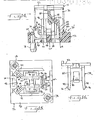
- Figure 7 is a top plan view of the housing and the lever,
- Figure 8 is a top plan view of the plunger,
- Figure 9 is a side view of the plunger,
- Figure 10 is a side view of the plunger as viewed from the right side of Figure 9,
- Figure 11 is a bottom view of the plunger,
- Figure 12 is a section along plane 12-12 of Figure 9,
- Figure 13 is a section along plane 13-13 of Figure 9,
- Figure 14 is a section, similar to Figure 2, illustrating an alternate embodiment of the invention, i.e., a linear switch,
- Figure 15 is a plan view of the housing for the linear switch of Figure 14, and
- Figure 16 is a side elevation view of the plunger for I the linear switch of Figure 14.
- The present invention relates to a keyboard switch in which the point of closure or "make point" is dependent on the geometry of the switch parts and not on the force applied to the switch. In other words, the switch will close only after the plunger has moved inwardly a given distance. Only upon such movement will the switch parts assume positions wherein the geometry of the parts allows application of a closing force to the membrane switch. The application of the closing force may be gradual or sudden. In the former case, the force applied to the membrane switch is a smooth, continuous function of the plunger travel; there are no sudden changes in the force. Since the force-deflection curve is generally a straight line, this switch is called a linear switch. In the latter case, an effectively instantaneous jump in the force-deflection curve is deliberately created so the user can feel it and know when the switch has closed. This is called a tactile switch. In both the linear and tactile switches the actuator lever is restrained from applying a switch closing force until the plunger has moved inwardly a given distance.
- The tactile switch of the present invention finds utility in keyboards, such as computer terminals, typewriters, calculators and other applications in which it is desirable that the key have a very low profile. For example, the total height of the entire key structure disclosed herein normally will not be greater than one-half inch. With a key construction of this dimension, the travel of the key actuator from the unoperated to the operated position will normally be quite small. In the present instance such travel may be on the order of slightly more than one-eighth inch. Heretofore, it has been a problem in keyboards of this size for the operator of the key to feel confident that in fact the key has been pressed in a manner as to insure a switch closure in the underlying membrane switch array. Thus, it is necessary for there to be a tactile feel in operation of the key or some indication to the user that in fact the key has been pressed to the degree necessary to cause operation of the switch. In one aspect the present invention is specifically directed to such a tactile key and to a means for providing a tactile feel in key operation. The tactile feel must not be a gradual sensation, but, rather,,there must be an abrupt or sudden movement in operation of the key so that the operator is assured and in fact completely confident that switch operation has taken place.
- Considering first Figures 1, 2 and 3, the tactile switch includes a housing indicated generally at 10 having a
central opening 12 mounting areciprocal plunger 14. The plunger may mount akeycap 16 of a conventional size and shape for keyboard operation. Pivotally mounted on the housing and in position to be in cooperative contact withplunger 14 is alever 18 which will be described in more detail hereinafter. -
Housing 12 is seated upon a membrane switch array which may consist of the conventionallower substrate 20,intermediate spacer 22 andmembrane 24. Conventionally, the membrane and substrate will have electrical contacts thereon which normally will be positioned beneathplunger 14. There will be theusual opening 26 in the spacer beneath the switch so that movement ofkeycap 16 and thus plunger 14 can effect a switch closure between the membrane and substrate. -
Housing 10 has acylindrical wall 28 which definesopening 12 and that portion ofhousing 10 beneath opening 12 may havearcuate slots 30 just inside ofwall 28, withslots 30 cooperating witharcuate projections 32 on the bottom of the plunger to maintain alignment and relative position between these two elements during switch operation. The bottom of the housing may have anopening 31 which will permitlever 18 to effect a switch closure. Further, in order to maintain the plunger within opening 12,housing 10 has oppositely-disposedhook elements 34, illustrated in Figure 6, which will ride in cooperatinggrooves 36 on the sides of the plunger. Note thatgrooves 36 have alower surface 38 forming a stop which prevents removal of the plunger from the housing opening. When the plunger is initially inserted during assembly, the plunger will be pushed pasthooks 34 which will flex to permit assembly. Once assembled, the plunger cannot be removed from the housing. -
Lever 18 has apivot portion 40 which is positioned within aslot 42 ofhousing portion 44 formed at one corner of the housing.Lever 18 is accordingly mounted for pivotal movement between the Figure 2 and 3 positions.Lever 18 has aspring support portion 46 which extends through an opening inwall 28 of the housing and provides aspring seat 48 which will seat acoil spring 50 which is captured between the spring seat and aninner surface 52 ofplunger 14. In addition,spring seat portion 46 oflever 18 includes a downwardprojecting boss 54 which is positioned, as specifically illustrated in Figure 3, to provide a closure of the underlying membrane switch by forcing a portion ofmembrane 24 through opening 26 in the spacer so that there is contact between the electrical conductive areas of the membrane and substrate. - The side of
plunger 14 which faceslever 18 has areset ramp 56 and athreshold ramp 58 with the reset ramp and threshold being separated by an open area or slot 60. To cooperate with the cam areas onplunger 14,lever 18 has anose 62 which is positioned in alignment withreset ramp 56 and anarm 64 which cooperates withthreshold 58 to hold the lever in the non-actuated position of Figures 2 and 4 until such time asarm 64 is in alignment withthreshold 58.Lever 18 further has astop 66 positioned directly behindarm 64 which restricts movement of the arm to a single plane. - The unoperated position of the switch is illustrated in Figure 2.
Coil spring 50 is seated upon thatportion 48 oflever 18 which extends intoopening 12 and the spring maintainsplunger 14 andkeycap 16 in the up or unoperated position. As the keycap, and hence the plunger, are depressed during switch operation,spring 50 will be compressed as the keycap moves toward the underlying membrane switch array. However, as illustrated in Figure 4,lever 18 will be maintained in the Figure 2 position because itsarm 64 will bear against the face ofthreshold 58. Only whenplunger 14 has been depressed a sufficient distance forarm 64 toclear threshold 58 can there be inward movement of the lever. Once the arm has cleared the threshold, the lever will suddenly move to the position of Figure 3 to effect a switch closure. The force which will drive the lever through such movement is that provided byspring 50. The spring is compressed as the keycap is moved inward. Once the lever is permitted to move to the switch closure position of Figure 3, the compressed spring will provide the necessary force to effect such sudden movement, - During reset or outward movement of the
keycap nose 62 oflever 18 will bear againstreset ramp 56. The cooperation between these two surfaces will cause the lever to pivot in a clockwise direction as the force ofspring 50 moves the keycap back to the position of Figure 2.Arm 64, as it is bearing againstthreshold 58, will to some degree retard the outward movement of the keycap, but the arm will flex in the single plane of its movement, as indicated in broken lines in Figure 5, as the plunger and keycap retract.Stop 66 will prevent the arm from moving in any direction other than in the vertical plane parallel withthreshold 58. Thus, the arm is protected bystop 66 and is permitted the flexing movement required so that the keycap and plunger can retract. Movement of the lever during the retraction of the plunger is controlled bynose 62 riding uponreset ramp 56. - Of particular importance in this aspect of the invention is the provision of a tactile feel driving switch closure. The sudden movement can be felt by the operator of the key, thereby giving the required tactile sensation to tell the operator that in fact the key has been moved to a switch closure position. The switch closure force is effected by the compression of the return spring during the downward movement of the key. The spring is compressed until such time as the plunger has moved inwardly a distance to permit the sudden movement required for a switch closure and this sudden movement is effected by the stored force in
spring 50. - We show the compound movement of the rocker member by pivotal movement in one plane and by flexing in another plane. The same type of compound movement can be derived by having the rocker mounted on a universal pivot or ball so that it can pivot in two planes.
- Figures 14-16 illustrate an alternate embodiment of the invention. This is the linear switch referred to above. Linear switch 70 has three main parts; a
housing 72, aplunger 74 and aspring 76. It will be understood that the switch is designed for use with a membrane switch array mounted on a base plate, although the membrane switch array and base plate are not shown. The switch is attached to the base plate by a pair ofexpandable rivets 78. - The
plunger 74 includes abody portion 80 to which acap 82 is connected. The cap engages thespring 76 as shown in Figure 14. An appropriate key top (not shown) would be attached to thecap 82. A pair of integrally formedlegs 84 extend from either side of thebody 80. Thelegs 84 carryhooks 86 near their ends. Acam surface 88 is formed on one side of thebody 80. As shown in Figure 14, the cam surface has a gradual, sloped configuration. - The
housing 72 includes a generallyflat base 90 having acentral opening 92 therein. A pair of upstanding walls are located in facing relation on either side of theopening 92. Each wall includes an elongatedlower portion 94 and a U-shapedupper portion 96 which extends above thelower portion 94. The bight of the U-shaped wall includes a groove orchannel 98 in which thehooks 86 of the plunger ride. Thegroove 98 extends about halfway up thewall portion 96. Its terminus forms an up stop for the plunger. Thelower portions 94 of the walls provide a base on which thespring 76 bottoms. - Other features of the housing include a
chamber 100 in which an optional cam follower may be inserted to provide an alternate action-type switch. The housing also has an upstanding spring support wall 102. Along with thewall portions 94, the spring support 102 provides a base on which thespring 76 rests. - An actuator lever is shown generally at 104. The lever is disposed above the
housing opening 92 and between thewalls actuator lever 104 includes an elongated,upright bracket 106. The bracket is pivotally attached to the base of the housing by aflexible hinge 108, commonly referred to as a living hinge. A pair ofextension pieces 110 are connected to the top of the bracket and extend downwardly therefrom. The extensions merge into a pair oflegs 112 which extend generally horizontally across the bottom of the housing. Thelegs 112 extend beyond thewall portions 96 and terminate with a pair ofupturned feet 114. Eachfoot 114 has twotabs 116 which form a slot between them for retaining thespring 76, as best seen in Figure 14. Thelegs 112 are connected by a strap 118. On the underside of the strap there is aknob 120 which is the part that actually contacts the membrane switch. - A
cam surface 122 is formed at the upper end of thebracket 106. This surface is in the nature of a cam follower as it engages thecam surface 88 on theplunger 74. - The operation of the linear switch is as follows. The
plunger body 80 andlegs 84 are disposed in the housing between theU-shaped walls 96. Thehooks 86 slide in the grooves 98 and are retained therein. Thespring 76 is compressed between theplunger cap 82 and thelower wall portions 94, the spring support 102 and thefeet 114 of theactuator lever 104. Thus, the spring urges the lever toward the membrane switch, i.e., in a counterclockwise direction (as seen in Figure 14) about thehinge 108. When the switch is in the unoperated, rest position (as in Figure 14) the lever is restrained from moving into a membrane switch closing position by the engagement of thecam follower 122 on thecam surface 88. When a user pushes the plunger inwardly, thecam surface 88 allows thelever 104 to pivot about thehinge 108 and bring theknob 120 into contact with the membrane switch. The compressed spring acts on the lever to gradually apply a membrane switch closing force through theknob 120. As can be seen in Figure 14, thecam surface 88 has a sloped configuration. This permits the gradual application of switch closing force in a smooth and continuous manner. When the user releases the plunger thespring 76 causes the plunger to move outwardly in the housing while at the same time thecam surface 88 resets theactuator lever 104 to its rest or non-operative position. It can be seen that thecam surface 88 prevents the lever from moving to a switch closing position until the plunger has moved inwardly a given distance. That distance can be regulated by the shape of the cam surface. - It will be understood that the
cam surface 88 does not have to have a smooth and continuous configuration. It could also have a sharp step or drop-off which would prevent any movement of the lever until the last possible moment. Then the lever would be released suddenly with the switch closing force being applied effectively instantaneously. This would provide a tactile feel as in the switch of Figures 1-13. - Whereas the preferred form of the invention has been shown and described herein, it should be realized that there may be many modifications, substitutions and alterations thereto.
Claims (12)
- The embodiments of the invention in which an exclusive property or privilege is claimed are defined as follows:
- 1. A low profile keyboard switch having tactile feel for use in combination with a membrane switch array, including a housing adapted to be positioned on a membrane switch array, an upright opening in said housing, a plunger reciprocal in said housing, an actuator lever pivotally mounted on said housing and positioned for engagement by said plunger, spring means seated upon said lever and urging said plunger outwardly in said opening, cooperating cam surfaces on said plunger and lever preventing movement of said lever to a membrane switch closing position until said plunger has moved inwardly a given distance, inward movement of said plunger compressing said spring means with movement of said plunger beyond the given distance causing the sudden application of a switch closing force, from said compressed spring means, by said lever on the underlying switch array.
- 2. The switch of claim 1 further characterized in that said lever has a portion aligned with said plunger and extending into said opening, said spring means being positioned between said lever portion and said plunger.
- 3. The switch of claim 2 further characterized in that said cooperating cam surfaces includes an arm on said lever and a threshold on said plunger, said threshold holding said lever in a non-membrane switch operative position until the plunger has moved inwardly the distance to permit said arm to pass said threshold, whereby said lever will suddenly move, in response to force from said spring means, to a switch closing position.
- 4. The switch of claim 3 further characterized in that said cooperating cam means includes a reset ramp, with a portion of said lever being in engagement with said reset ramp when said plunger moves outwardly of said opening to return to a non-actuated position.
- 5. The switch of claim 1 further characterized in that said lever includes an inner projecting surface located directly above a membrane switch array to cause actuation thereof.
- 6. The switch of claim 1 further characterized in that said spring means is a coil spring extending within said plunger, said lever having a portion extending into said opening, underlying said plunger and seating said coil spring, inward movement of said plunger compressing said spring whereby inward movement of said plunger through the given distance causing the sudden pivotal movement of said lever, with said spring applying a switch closing force thereto.
- 7. The switch of claim 6 further characterized by and including an arm on said lever in contact with a threshold portion of said plunger, inward movement of said plunger through the given distance permitting said arm to move past said threshold, thereby permitting pivotal movement of said lever to a switch closing position.
- 8. A keyboard switch for use in combination with a membrane switch array, including a housing adapted to be positioned on a membrane switch array, an upright opening in said housing, a plunger reciprocal in said housing, an actuator lever pivotally mounted on said housing and positioned for engagement by said plunger, spring means seated upon said lever and urging said plunger outwardly in said opening, cooperating cam surfaces on said plunger and lever preventing movement of said lever to a membrane switch closing position until said plunger has moved inwardly a given distance, inward movement of said plunger compressing said spring means with movement of said plunger beyond the given distance allowing the application of a switch closing force, from said compressed spring means, by said lever on the underlying switch array.
- 9. The switch of claim 8 wherein the cam surfaces have a sloped configuration such that the lever gradually applies a switch closing force on the membrane switch array.
- 10. The switch of claim 8 wherein the cam surfaces have a discontinuous configuration such that the lever initially is restrained in a non-operative position and then is released to apply a sudden switch closing force and provide a tactile feedback.
- 11. The switch of claim 8 wherein the actuator lever is connected to the housing by an integral hinge.
Priority Applications (1)
| Application Number | Priority Date | Filing Date | Title |
|---|---|---|---|
| AT84100040T ATE30982T1 (en) | 1983-11-21 | 1984-01-03 | KEYBOARD SWITCH WITH ROTATING ACTUATION LEVER. |
Applications Claiming Priority (2)
| Application Number | Priority Date | Filing Date | Title |
|---|---|---|---|
| US553966 | 1983-11-21 | ||
| US06/553,966 US4553009A (en) | 1982-09-03 | 1983-11-21 | Keyboard switch with pivotal actuator lever |
Publications (2)
| Publication Number | Publication Date |
|---|---|
| EP0142593A1 true EP0142593A1 (en) | 1985-05-29 |
| EP0142593B1 EP0142593B1 (en) | 1987-11-19 |
Family
ID=24211508
Family Applications (1)
| Application Number | Title | Priority Date | Filing Date |
|---|---|---|---|
| EP84100040A Expired EP0142593B1 (en) | 1983-11-21 | 1984-01-03 | Keyboard switch with pivotal actuator lever |
Country Status (5)
| Country | Link |
|---|---|
| US (1) | US4553009A (en) |
| EP (1) | EP0142593B1 (en) |
| JP (1) | JPS60131721A (en) |
| AT (1) | ATE30982T1 (en) |
| DE (1) | DE3467658D1 (en) |
Cited By (7)
| Publication number | Priority date | Publication date | Assignee | Title |
|---|---|---|---|---|
| EP0353900A1 (en) * | 1988-08-02 | 1990-02-07 | Acer Peripherals, Inc. | Keyboard switch |
| EP0464339A2 (en) * | 1990-07-05 | 1992-01-08 | GRUNDIG E.M.V. Elektro-Mechanische Versuchsanstalt Max Grundig holländ. Stiftung & Co. KG. | Push button switch installation for an electronic apparatus |
| EP0543649A2 (en) * | 1991-11-19 | 1993-05-26 | Brother Kogyo Kabushiki Kaisha | Keyswitch assembly |
| US5278374A (en) * | 1992-02-14 | 1994-01-11 | Brother Kogyo Kabushiki Kaisha | Assembly with an asymmetrical resilient spring |
| US5278372A (en) * | 1991-11-19 | 1994-01-11 | Brother Kogyo Kabushiki Kaisha | Keyboard having connecting parts with downward open recesses |
| US5278371A (en) * | 1992-02-14 | 1994-01-11 | Brother Kogyo Kabushiki Kaisha | Keyswitch assembly with support mechanism coupled to support plate beneath printed circuit board |
| EP0749136A2 (en) * | 1995-06-14 | 1996-12-18 | Elektro-Apparatebau Olten AG | Switch for opening a door |
Families Citing this family (16)
| Publication number | Priority date | Publication date | Assignee | Title |
|---|---|---|---|---|
| DE3530050A1 (en) * | 1985-08-22 | 1987-02-26 | Cherry Mikroschalter Gmbh | KEY MODULE FOR FILM KEYBOARDS |
| US4761522A (en) * | 1986-10-06 | 1988-08-02 | Allen Donald E | Finger operated switching apparatus |
| US4769516A (en) * | 1986-10-06 | 1988-09-06 | Allen Donald E | Finger operated switching apparatus |
| JPH01150337U (en) * | 1988-04-11 | 1989-10-18 | ||
| US4899244A (en) * | 1988-07-28 | 1990-02-06 | Polaroid Corporation | Disk cartridge with hub seal |
| US4939327A (en) * | 1988-10-31 | 1990-07-03 | Acer Incorporated | Keyboard switch |
| US4931606A (en) * | 1989-04-28 | 1990-06-05 | International Business Machines Corporation | Key switch mechanism and membrane actuator |
| GB2238912A (en) * | 1989-07-28 | 1991-06-12 | Acer Inc | Pushbutton switch assembly |
| US5668358A (en) * | 1994-07-05 | 1997-09-16 | Ultimate Rechnology Corporation | Reconfigurable keyboard |
| WO1997008720A1 (en) * | 1995-08-23 | 1997-03-06 | Matsushita Electric Industrial Co., Ltd. | Operation type electronic component |
| JP2018005700A (en) * | 2016-07-05 | 2018-01-11 | 富士通コンポーネント株式会社 | Keyboard |
| US10930451B2 (en) * | 2018-06-22 | 2021-02-23 | Darfon Electronics Corp. | Keyswitch with adjustable tactile feedback |
| US10937610B2 (en) | 2018-06-22 | 2021-03-02 | Darfon Electronics Corp. | Keyboard keyswitches having adjustable tactile feedback members |
| US11557444B2 (en) * | 2020-06-04 | 2023-01-17 | Hewlett-Packard Development Company, L.P. | Keyboard key switches |
| US11373822B2 (en) * | 2020-06-04 | 2022-06-28 | Hewlett-Packard Development Company, L.P. | Keyboard key switches |
| CN116798795A (en) * | 2022-03-17 | 2023-09-22 | 致伸科技股份有限公司 | Keyboard device and key structure thereof |
Citations (6)
| Publication number | Priority date | Publication date | Assignee | Title |
|---|---|---|---|---|
| US3757068A (en) * | 1971-04-15 | 1973-09-04 | Hewlett Packard Co | Sms keyboard actuating mechanism with particular feel and contact mechani |
| DE2346392A1 (en) * | 1972-09-15 | 1974-03-28 | Victor Comptometer Corp | KEYBOARD, IN PARTICULAR FOR ELECTRONIC COMPUTERS |
| US3969600A (en) * | 1975-06-11 | 1976-07-13 | Burroughs Corporation | Tactile feedback keyboard switch assembly and actuator |
| DE3111407A1 (en) * | 1981-03-24 | 1982-10-21 | Marquardt Gmbh, 7201 Rietheim-Weilheim | Push-button switch |
| US4367380A (en) * | 1980-08-27 | 1983-01-04 | Oak Industries Inc. | Keyboard assembly and components therefor |
| EP0118131A2 (en) * | 1983-03-07 | 1984-09-12 | Oak Industries Inc. | Tactile feel switch with positive switch actuation |
Family Cites Families (8)
| Publication number | Priority date | Publication date | Assignee | Title |
|---|---|---|---|---|
| US3656181A (en) * | 1970-10-20 | 1972-04-11 | Teletype Corp | Magnetically operable momentary switch assembly |
| US4314112A (en) * | 1971-08-23 | 1982-02-02 | Hewlett-Packard Company | Keyboard having switches with tactile feedback |
| US3856998A (en) * | 1973-06-01 | 1974-12-24 | Burroughs Corp | Keyboard switch assembly with improved operating means |
| US3982081A (en) * | 1974-09-04 | 1976-09-21 | Amp Incorporated | Keyboard assembly with overlapped flexible printed circuit cable switch |
| JPS6025782Y2 (en) * | 1978-05-25 | 1985-08-02 | アルプス電気株式会社 | push button switch |
| DE2838934C2 (en) * | 1978-09-07 | 1986-07-31 | J. & J. Marquardt, 7201 Rietheim-Weilheim | Electric switch |
| US4447681A (en) * | 1983-02-22 | 1984-05-08 | Amp Incorporated | Switch key assembly having improved switch actuation |
| US4450331A (en) * | 1983-06-08 | 1984-05-22 | Amp Incorporated | Key switch assembly having momentary closed interval |
-
1983
- 1983-11-21 US US06/553,966 patent/US4553009A/en not_active Expired - Fee Related
-
1984
- 1984-01-03 DE DE8484100040T patent/DE3467658D1/en not_active Expired
- 1984-01-03 EP EP84100040A patent/EP0142593B1/en not_active Expired
- 1984-01-03 AT AT84100040T patent/ATE30982T1/en not_active IP Right Cessation
- 1984-01-20 JP JP59008369A patent/JPS60131721A/en active Granted
Patent Citations (6)
| Publication number | Priority date | Publication date | Assignee | Title |
|---|---|---|---|---|
| US3757068A (en) * | 1971-04-15 | 1973-09-04 | Hewlett Packard Co | Sms keyboard actuating mechanism with particular feel and contact mechani |
| DE2346392A1 (en) * | 1972-09-15 | 1974-03-28 | Victor Comptometer Corp | KEYBOARD, IN PARTICULAR FOR ELECTRONIC COMPUTERS |
| US3969600A (en) * | 1975-06-11 | 1976-07-13 | Burroughs Corporation | Tactile feedback keyboard switch assembly and actuator |
| US4367380A (en) * | 1980-08-27 | 1983-01-04 | Oak Industries Inc. | Keyboard assembly and components therefor |
| DE3111407A1 (en) * | 1981-03-24 | 1982-10-21 | Marquardt Gmbh, 7201 Rietheim-Weilheim | Push-button switch |
| EP0118131A2 (en) * | 1983-03-07 | 1984-09-12 | Oak Industries Inc. | Tactile feel switch with positive switch actuation |
Cited By (11)
| Publication number | Priority date | Publication date | Assignee | Title |
|---|---|---|---|---|
| EP0353900A1 (en) * | 1988-08-02 | 1990-02-07 | Acer Peripherals, Inc. | Keyboard switch |
| EP0464339A2 (en) * | 1990-07-05 | 1992-01-08 | GRUNDIG E.M.V. Elektro-Mechanische Versuchsanstalt Max Grundig holländ. Stiftung & Co. KG. | Push button switch installation for an electronic apparatus |
| EP0464339A3 (en) * | 1990-07-05 | 1992-08-19 | Grundig E.M.V. Elektro-Mechanische Versuchsanstalt Max Grundig Hollaend. Stiftung & Co. Kg. | Push button switch installation for an electronic apparatus |
| EP0543649A2 (en) * | 1991-11-19 | 1993-05-26 | Brother Kogyo Kabushiki Kaisha | Keyswitch assembly |
| EP0543649A3 (en) * | 1991-11-19 | 1993-07-07 | Brother Kogyo Kabushiki Kaisha | Keyswitch assembly |
| US5278372A (en) * | 1991-11-19 | 1994-01-11 | Brother Kogyo Kabushiki Kaisha | Keyboard having connecting parts with downward open recesses |
| US5280147A (en) * | 1991-11-19 | 1994-01-18 | Brother Kogyo Kabushiki Kaisha | Keyswitch assembly with a key support limiting transverse, longitudinal and rotational movement of the key |
| US5278374A (en) * | 1992-02-14 | 1994-01-11 | Brother Kogyo Kabushiki Kaisha | Assembly with an asymmetrical resilient spring |
| US5278371A (en) * | 1992-02-14 | 1994-01-11 | Brother Kogyo Kabushiki Kaisha | Keyswitch assembly with support mechanism coupled to support plate beneath printed circuit board |
| EP0749136A2 (en) * | 1995-06-14 | 1996-12-18 | Elektro-Apparatebau Olten AG | Switch for opening a door |
| EP0749136A3 (en) * | 1995-06-14 | 1998-04-29 | Elektro-Apparatebau Olten AG | Switch for opening a door |
Also Published As
| Publication number | Publication date |
|---|---|
| EP0142593B1 (en) | 1987-11-19 |
| JPS60131721A (en) | 1985-07-13 |
| DE3467658D1 (en) | 1987-12-23 |
| ATE30982T1 (en) | 1987-12-15 |
| JPH0345497B2 (en) | 1991-07-11 |
| US4553009A (en) | 1985-11-12 |
Similar Documents
| Publication | Publication Date | Title |
|---|---|---|
| US4553009A (en) | Keyboard switch with pivotal actuator lever | |
| US4467160A (en) | Low profile switch | |
| EP0543649A2 (en) | Keyswitch assembly | |
| EP0311024A2 (en) | Microswitch | |
| US5803243A (en) | Latching rocker switch | |
| US5486669A (en) | Detented paddle blade switch assembly | |
| US6087604A (en) | Thin keyboard | |
| US5012055A (en) | Spring loaded push-button switch having predictable switching time despite varying spring characteristics | |
| CA1160269A (en) | Pushbutton key switch | |
| US20020079204A1 (en) | Foot operated switch for electrical circuits | |
| US4904832A (en) | Microswitch | |
| US4613737A (en) | Low profile pushbutton switch with tactile feedback | |
| CA1312896C (en) | Pushbutton switch, particularly key switch | |
| US6541716B2 (en) | Multidirectional switch device in which differences in tactile feel are reduced | |
| JPH0526652Y2 (en) | ||
| CA1213927A (en) | Keyboard switch with pivotal actuator lever | |
| GB2058458A (en) | Key switch | |
| US6504122B2 (en) | Control device for a push-button type switch | |
| US4361743A (en) | Lost motion keyswitch | |
| US4571467A (en) | Three position center-off electrical switch | |
| EP0138136A2 (en) | Slide switch sideways operation adapter | |
| EP0314925B1 (en) | Microswitch | |
| EP0353900B1 (en) | Keyboard switch | |
| TW420812B (en) | Pushbutton switch | |
| JPH07107817B2 (en) | Microswitch |
Legal Events
| Date | Code | Title | Description |
|---|---|---|---|
| PUAI | Public reference made under article 153(3) epc to a published international application that has entered the european phase |
Free format text: ORIGINAL CODE: 0009012 |
|
| AK | Designated contracting states |
Designated state(s): AT BE CH DE FR GB IT LI NL SE |
|
| 17P | Request for examination filed |
Effective date: 19850403 |
|
| 17Q | First examination report despatched |
Effective date: 19860528 |
|
| GRAA | (expected) grant |
Free format text: ORIGINAL CODE: 0009210 |
|
| AK | Designated contracting states |
Kind code of ref document: B1 Designated state(s): AT BE CH DE FR GB IT LI NL SE |
|
| REF | Corresponds to: |
Ref document number: 30982 Country of ref document: AT Date of ref document: 19871215 Kind code of ref document: T |
|
| ITF | It: translation for a ep patent filed |
Owner name: DE DOMINICIS & MAYER S.R.L. |
|
| REF | Corresponds to: |
Ref document number: 3467658 Country of ref document: DE Date of ref document: 19871223 |
|
| ET | Fr: translation filed | ||
| PLBE | No opposition filed within time limit |
Free format text: ORIGINAL CODE: 0009261 |
|
| STAA | Information on the status of an ep patent application or granted ep patent |
Free format text: STATUS: NO OPPOSITION FILED WITHIN TIME LIMIT |
|
| 26N | No opposition filed | ||
| ITTA | It: last paid annual fee | ||
| PGFP | Annual fee paid to national office [announced via postgrant information from national office to epo] |
Ref country code: NL Payment date: 19910131 Year of fee payment: 8 |
|
| PGFP | Annual fee paid to national office [announced via postgrant information from national office to epo] |
Ref country code: GB Payment date: 19910620 Year of fee payment: 8 Ref country code: AT Payment date: 19910620 Year of fee payment: 8 |
|
| PGFP | Annual fee paid to national office [announced via postgrant information from national office to epo] |
Ref country code: CH Payment date: 19910621 Year of fee payment: 8 |
|
| PGFP | Annual fee paid to national office [announced via postgrant information from national office to epo] |
Ref country code: FR Payment date: 19910625 Year of fee payment: 8 |
|
| PGFP | Annual fee paid to national office [announced via postgrant information from national office to epo] |
Ref country code: SE Payment date: 19910627 Year of fee payment: 8 |
|
| PGFP | Annual fee paid to national office [announced via postgrant information from national office to epo] |
Ref country code: BE Payment date: 19910705 Year of fee payment: 8 |
|
| PGFP | Annual fee paid to national office [announced via postgrant information from national office to epo] |
Ref country code: DE Payment date: 19910930 Year of fee payment: 8 |
|
| PG25 | Lapsed in a contracting state [announced via postgrant information from national office to epo] |
Ref country code: GB Effective date: 19920103 Ref country code: AT Effective date: 19920103 |
|
| PG25 | Lapsed in a contracting state [announced via postgrant information from national office to epo] |
Ref country code: SE Effective date: 19920104 |
|
| PG25 | Lapsed in a contracting state [announced via postgrant information from national office to epo] |
Ref country code: LI Effective date: 19920131 Ref country code: CH Effective date: 19920131 Ref country code: BE Effective date: 19920131 |
|
| BERE | Be: lapsed |
Owner name: OAK INDUSTRIES INC. Effective date: 19920131 |
|
| PG25 | Lapsed in a contracting state [announced via postgrant information from national office to epo] |
Ref country code: NL Effective date: 19920801 |
|
| GBPC | Gb: european patent ceased through non-payment of renewal fee | ||
| NLV4 | Nl: lapsed or anulled due to non-payment of the annual fee | ||
| PG25 | Lapsed in a contracting state [announced via postgrant information from national office to epo] |
Ref country code: FR Effective date: 19920930 |
|
| REG | Reference to a national code |
Ref country code: CH Ref legal event code: PL |
|
| PG25 | Lapsed in a contracting state [announced via postgrant information from national office to epo] |
Ref country code: DE Effective date: 19921001 |
|
| REG | Reference to a national code |
Ref country code: FR Ref legal event code: ST |
|
| EUG | Se: european patent has lapsed |
Ref document number: 84100040.9 Effective date: 19920806 |