EP0144924B1 - True-perspective texture/shading processor - Google Patents
True-perspective texture/shading processor Download PDFInfo
- Publication number
- EP0144924B1 EP0144924B1 EP84114506A EP84114506A EP0144924B1 EP 0144924 B1 EP0144924 B1 EP 0144924B1 EP 84114506 A EP84114506 A EP 84114506A EP 84114506 A EP84114506 A EP 84114506A EP 0144924 B1 EP0144924 B1 EP 0144924B1
- Authority
- EP
- European Patent Office
- Prior art keywords
- texture
- shading
- face
- data
- edge
- Prior art date
- Legal status (The legal status is an assumption and is not a legal conclusion. Google has not performed a legal analysis and makes no representation as to the accuracy of the status listed.)
- Expired - Lifetime
Links
Images


Classifications
-
- G—PHYSICS
- G09—EDUCATION; CRYPTOGRAPHY; DISPLAY; ADVERTISING; SEALS
- G09B—EDUCATIONAL OR DEMONSTRATION APPLIANCES; APPLIANCES FOR TEACHING, OR COMMUNICATING WITH, THE BLIND, DEAF OR MUTE; MODELS; PLANETARIA; GLOBES; MAPS; DIAGRAMS
- G09B9/00—Simulators for teaching or training purposes
- G09B9/02—Simulators for teaching or training purposes for teaching control of vehicles or other craft
- G09B9/08—Simulators for teaching or training purposes for teaching control of vehicles or other craft for teaching control of aircraft, e.g. Link trainer
- G09B9/30—Simulation of view from aircraft
- G09B9/301—Simulation of view from aircraft by computer-processed or -generated image
-
- G—PHYSICS
- G06—COMPUTING; CALCULATING OR COUNTING
- G06T—IMAGE DATA PROCESSING OR GENERATION, IN GENERAL
- G06T15/00—3D [Three Dimensional] image rendering
- G06T15/50—Lighting effects
-
- G—PHYSICS
- G06—COMPUTING; CALCULATING OR COUNTING
- G06T—IMAGE DATA PROCESSING OR GENERATION, IN GENERAL
- G06T15/00—3D [Three Dimensional] image rendering
- G06T15/50—Lighting effects
- G06T15/80—Shading
Definitions
- the present invention generally relates to computer image generation (CIG) systems that produce images in "real time” for visual training simulators, and more particularly to a low cost, true-perspective texture/shading processor for raster graphics.
- CCG computer image generation
- the principle application area for CIG has been that of visual training simulators which present scenes to an observer or trainee to allow the observer to practice some task, such as flying an airplane.
- a flight simulator a three-dimensional model of the desired "gaming area" is prepared and stored on magnetic disk or similar bulk storage media. This model is called the visual data base.
- the visual simulator combines an image generator with an electro-optical display system such as a cathode ray tube (CRT) or similar display.
- the image generator reads in blocks of three-dimensional data from the disk and transforms this data into two-dimensional scene descriptions.
- a single simulator may be required to provide several different scenes, as, for example, in the case of an airplane having several windows in the cockpit.
- the two-dimensional data are converted to analog video that is presented to the operator via the display.
- the generated imagery is meant to be representative of the true scenes that the operator would see if the operator were actually performing the task being simulated.
- the generation of the display images is said to be in "real time" which is normally taken to mean 30 frames per second, as in the U.S. television standard.
- CIG systems are described in detail in the book entitled Computer Image Generation edited by Bruce J. Schachter and published by Wiley-Interscience (1983). In this context reference is also made to an earlier publication of Bruce J. Schachter: "Real Time Display of Textures", Proceedings of the 5th International Conference on Pattern Recognition, Florida, 01-04 December 1980, Vol. 2, pages 789 to 291, IEEE, New York, US.
- This paper relates to an image generation system for generating textured surfaces in real time. The operations are carried out by three cycles (Frames I, II, III) which are connected serially.
- US 3 999 308 relates to an image generator including texture/shading generator means which processes the texture portion of the data to activate face areas on a CRT display.
- Absolute realism is not achieved in CIG systems, but notably the training mission can be accomplished satisfactorily despite this apparent drawback. Recent developments have, moreover, remarkably improved the degree of realism attainable.
- texture and shading Natural scenes are rich in texture, and the human eye relies heavily on texture cues to perceive the structure of a scene.
- suitable texture is required to create the visual sensations of air speed, altitude, horizon angle, and location in the environment. From a scene- processing point of view, the addition of texture to the displayed faces, i.e. planar portions of a modeled surface of the simulated scene, increases the information content without increasing the number of faces to be processed.
- the objects of the invention are attained by the development of a mathematical model which defines modulations globally over the entire simulated, visual environment yet still provides correct, true-perspective computation of the face modulations in the raster image.
- This global mathematical model is generated, stored and processed using a much smaller amount of digital hardware.
- the basic innovation which achieves this reduction in hardware, and therefore cost, is the use of texture and shading gradients defined in three-dimensional space, instead of in each face plane, to define the texture and shading modulations. Three gradients are used. For shading, one gradient is used for each axis of the coordinate system in which the visual environment is modeled. Each gradient defines the manner in which a unit vector normal to the modeled surface varies in the direction of the corresponding axis.
- One set of gradients is used for each shaded object.
- all three gradients are defined in a nominal, flat ground plane.
- Each gradient defines a parallel series of planes of equal intensity.
- a reference point and reference value are also defined.
- the gradients define the variation of the surface normal or the texture stripe number relative to the reference value.
- the basic CIG system in which the subject invention is incorporated consists of three major components termed Frame I, Frame II and Frame III.
- the "Frame i" designation refers to groupings of functions that were alloted one frame time (i.e., 1/30 seconds) for computation. The entire process therefore required three frame times from start to finish. While these conditions no longer hold true in general, the terms are still useful for identification purposes.
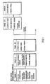
- Figure 1 shows the overall functional diagram of the CIG system. Frame I computations are normally performed in a minicomputer with a large magnetic disk storage. In this frame, the position of the viewpoint and any moving models, such as other aircraft, are determined in a common coordinate system.
- Frame I The principal function performed by Frame I is to manage the data base transferring data from disk storage to the active environment storage in Frame II to provide the subsequent processing with a description of the surrounding environment.
- Frame I also generates trigonometric coefficients required for perspective transformation and performs system executive functions such as, for example, maintenance.
- Frame II is part of a special-purpose computer.
- the function of Frame II can be thought of as reducing a three-dimensional description of the environment to a two-dimensional description for each viewing window.
- Frame II contains a rather large active-environment store that provides the data necessary to generate the scene from the viewpoint location.
- the active-environment storage is accessed by Frame II to obtain only that data that describes the scene as viewed through the view window of each display channel.
- the data undergoes a perspective correction to transform it into the coordinates of each view window.
- the data receives a channel assignment that will be used later to route it to the proper display channel.
- Frame II also assigns a priority to each surface in the scene. The priorities are assigned so that surfaces closer to the viewpoint have a higher priority than more distant surfaces. These priorities are used in subsequent processing to determine which surface should be displayed when one object is occulted by another.
- Frame III essentially has the function of reducing the two-dimensional representation of a scene to a scan line or a one-dimensional representation.
- Frame III is broken into two halves: Frame IIIA, which serves all display channels, and Frame IIIB, which is replicated for each display channel.
- Frame IIIA generates edge data from the vertex desgination used in earlier processing. This edge data locates where the edge crosses a scan line, describes the characteristics of the surface to the right of the edge, and is generated for each scan line crossing the edge. After the edge data is ordered, the priority data is used to eliminate edge data for hidden surfaces.
- Frame IIIB processes the lists of edge crossings it receives to generate video for the displays. It performs an edge smoothing to eliminate undesirable quantization effects, performs curved-surface shading, and generates texture for surfaces that are to receive a texture pattern.
- the computations required in Frame IIIB are relatively straight forward but must be performed at very high pixel rates (30 ⁇ 40 MHz) which accounts for the usually high costs of this subsystem. More specifically, the computation of face modulation in previous CIG systems has required that different patterns be stored for each face in a digital data base and that these patterns be processed separately for each face. This has required large storage and computational hardware.
- the present invention is an improvement to this subsystem that radically reduces the required storage and computation and therefore greatly reduces the costs of the subsystem.
- This reduction is accomplished by the development of a mathematical model which defines the modulations globally over the entire simulated, visual environment, yet still provides correct, true-perspective computation of the face modulations in the raster image.
- This global math model is generated, stored, and processed using a much smaller amount of digital hardware.
- the display subsystem consists of either a CRT or light valve projector to produce an image from the video.
- the display subsystem includes some optics designed to place the image at infinity relative to the viewpoint.
- FIG. 2 is functional block diagram of the CIG system of Figure 1 drawn to emphasize face modulation processing 13 and the texture/shading generator 16 of the present invention.
- a disk storage 10 contains the visual data base (VDB) that is supplied to Frames I and II.
- Frame I loads in processor 12 the environment data blocks (EDB's) of the VDB, describing the geometry of the data base to vertex, face/edge, color, and priority processing.
- Processor 12 is part of Frame II.
- Frame I also supplies to processor 12 dynamic data in the form of a viewpoint vector V relative to the environment coordinate system and a direction cosine matrix [DC] VP ENV to rotate the environment from its coordinate set (x, y, z) into that of the view point (u, v, w).
- Frame II uses this data to perform a perspective mapping of the face edges of the environment into the view plane.
- This edge data is sent to the edge generator 14 of Frame III which computes the intersections (edge-crossings) of the edges with each raster line and orders these by element number.
- the ordered edge crossings, together with face priority and color data are used by the priority resolver 15 to eliminate hidden edges.
- the priority resolver 15 supplies to the video processor 17 an ordered list of edge crossings with pixel area and color data.
- the texture/shading generator 16 generates texture, shading and fading modulation data for up to three face areas in each of four pixels during every 120 ns. logic clock interval.
- the texture modulation values are between 0.0 and 2.0 and may be different for each pixel.
- the fading modulation values F are between 0.0 and 1.0 and are identical for the four pixels.
- the video processor 17 applies the texture and fading modulations to each of the three face areas per pixel according to the followinq equation: where
- texture is a modulation of a face in the form of a series of parallel stripes of varying intensities
- a brief digression at this point should serve to place the subject invention in proper perspective.
- individual edges would have been used to model the boundaries of each stripe.
- a single gradient vector in the plane of the face can indicate the spacing and orientation of the series of stripes.
- a modeler defines texture by specifying from one to three gradients in the plane of each textured face. In addition to these gradients, a texture map number and a starting point for the map are assigned to each gradient to indicate the modulation values associated with each stripe.
- This method allows each face to be textured differently without subdividing the faces into edges; however, it still requires about 45 bytes of data to define the gradients, start values, and texture map codes for each different texture.
- the storage and processing of this data are comparable to the storage and processing for about four edges per face. For very large faces, this provides an economical reduction compared to processing every texture edge independently. Further reductions in memory. and computations are still needed to provide truly low-cost systems.
- the present invention allows a continuous texture pattern covering any number of faces to be specified by a single set of gradients, start values and map codes. This method not only reduces data storage requirements, but it also eliminates the need to project gradients independently for each face. Finally, because the texture for all faces representing the same type of surface is specified by a single set of data, it is easy to modify a texture, whether to improve its appearance, to correct a modeling error, or to simulate motion of a surface, e.g. flowing water.
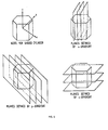
- Figure 4 shows a cross-section of such a terrain which is segmented by a series of texture planes.
- the texture planes are all orthogonal to a single gradient in a flat reference plane. These planes may cut across any number of faces. Where the intersections occur, texture stripes will be defined. These texture stripes have two important properties. First, they will match up at all face boundaries, assuring continuity of texture. Second, although their relative spacing will vary with the slope of each face, they will have a constant spacing in any x-y plane. This kind of geometry is expected for many types of features frequently represented by texture such as, for example, plowed furrows, fields, city blocks, or tree lines. Other textures, such as lines of bricks in a wall, might be defined by a series of horizontal planes. The same set of planes could be used for any wall with equally spaced bricks.
- Shading like texturing, has been defined by gradients in the face plane.
- the shading gradients define the vector normal to any point on an object surface.
- this vector normal much like the texture stripes, should match at each edge of an object in order to create the appearance of smoothness of the surface at that edge. Therefore, a single set of gradients can be defined for each shaded object of the visual environment model. This is illustrated in Figure 5.
- the present invention computes the point on each textured/shaded face onto which each pixel of the image raster falls when it is inverse perspectively mapped from the view plane into the visual environment. It then determines the location of this point relative to the parallel planes defining the texturing or shading pattern.
- the mathematics by which this mapping is computed is as follows.
- the planes defining either a texture or a shading pattern can be defined by the locus of points in the environment satisfying the following equation: wiiere
- the coordinate u is the distance along an orthogonal to the view plane from the view point to point a. From the figure, where or where and
- the present invention includes face modulation processor 13, which is added to Frame II and computes the face and pattern coefficients, and the texture/shading generator 16, which is added to Frame III and computes the texturing and/or shading modulation on a pixel-by-pixel basis. Because the operations of face modulation processor 13 are greatly simplified by the math model for textu ring/shading of the present invention, these operations are performed using the existing Frame I general purpose computer and Frame II arithmetic pipelines of the basic image generator. Therefore, the only added hardware unit is the texture/ shading generator 16.
- the texture/shading generator 16 computes, for every group of four pixels, the inverse perspective mapping of that group onto the surface of one or two incident faces. From this mapping, it computes either a shading modulation or a texture modulation for each face at each of the four pixels of the group.
- FIG. 7 is a block diagram of the texture/shading generator.
- the texture/shading generator receives data in three ping-pong memories 30, 31 and 32.
- Data describing each texture or shading model is received from face modulation processor 13 and stored in the pattern memory 30.
- Data describing the plane of each textured or shaded face is also received every field time and is stored in the face memory 31.
- data describing each edge is received from the priority resolver 15 and stored in the edge memory 32.
- the two sides of the pattern memory 30 and the face memory 31 are exchanged every field time such that data for the field currently being displayed is being read out while data for the next field is being written.
- the two sides of the edge memory 32 are alternated every raster line time such that data for the line currently being displayed is being read out while data for the next line is being written.
- Figure 8 illustrates the subdivision of a raster line into pixels and pixel groups.
- Texturing/shading is computed for four pixels at a time in order to achieve high resolution video rates (approximately 25 to 30 MHz).
- One pixel group is computed every 120 ns.
- the basic operation of the texture/shading is to map each four-pixel group into one shading modulation for one or two faces or into one, two, or three texture stripe maps for one face.
- Two shaded faces are computed if an edge between two shaded faces appears in the four-pixel group. If there are more than one textured or two shaded faces in the group, then one or more face modulations are approximated by the value 1.0 or by the Face A or Face B modulation.
- the requirement to calculate two shaded faces while only one textured face can be computed is imposed because it is more important to avoid discontinuities in a shaded surface than in a textured surface.
- edge data is read from the edge memory 32.
- This data includes the element-value J L of a new edge to be processed, the face number to be used for new texture/shading calculations for that pixel group, and a "hold flag".
- the hold flag indicates that data for the current face is to be retained for shading path "B" computations in the next pixel group.
- the face number read from the edge memory 32 is used to address face data in the face memory 31 which is stored by face number.
- the denominator coefficients C 4 , C S and C 6 are used for distance computation in calculators 35 and 36, while the texture code is used to address pattern data from the pattern memory 30 and to select the appropriate texture maps for texture computation.
- a Frame I data register 33 stores the line and element number of the pixel at the orthogonal to the view plane. These are used by edge crossing control 34 to compute a relative line number (I-lo) and element number (J-Jo) from the element-value J L and current line I.
- Calculators 35 and 36 perform distance calculations A and B by computing the distance u to the upper left, upper right and lower left corners of each pixel group for the current and previous face number, respectively.
- the formula used is The distances u " and u B calculated by the distance calculators 35 and 36 are used by base number calculators 37 and 38, respectively, to inverse perspectively transform the pixel groups into the shading modulations or texture stripe numbers.
- Base number calculator 37 maps the upper left corner of the pixel group into three texture stripe numbers or one shading modulation value for Face A. It also computes the change in stripe number over four elements (AP j ) or over four lines ( ⁇ P 1 ) for each of the three texture patterns and computes the shading modulation value at the upper right corner of the pixel group.
- Base number calculator 38 computes the shading modulation at the upper left and upper right corners of the pixel group for Face B, a previous face identified by the hold flag.
- the formulas are as follows:
- Figure 9 shows the distance calculation 35, 36 hardware configuration.
- This logic calculates the required distance terms in 22-bit floating point format.
- This format uses a 6-bit exponent and a 16-bit argument in two's complement form.
- the C 5 coefficient is multiplied in multiplier 50 by the 14-bit I-lo four pixel group line location.
- Multiplier 50 comprises 16-bit multiplier and exponent adder integrated circuits (ICs).
- the C 6 coefficient is multiplied in multiplier 52 by the 14-bit J-Jo four pixel group element location.
- Multiplier 52 is similar to multiplier 50.
- the results of these multiplications are added in adders 54 and 56 to the C 4 starting coefficient using floating point arithmetic logic unit (ALU) ICs.
- ALU floating point arithmetic logic unit
- the result is the distance term for the I,J (D,) element position of the four pixel group.
- the reciprocal of this distance term is calculated using firmware lookup and summers in a Taylor series expansion unit 58.
- the reciprocal is used to implement the hardware divide to allow a multiply operation instead of the more difficult divide operation.
- the distance calculation for the four line position is obtained by adding four times the C 5 coefficient to the D l,J result in adder 60.
- the distance calculation for the four element position is obtained by adding four times the C 6 coefficient to the D,, j result in adder 62.
- the reciprocal for these two locations is also taken in firmware units 64 and 66.
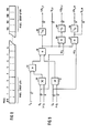
- the numerator calculation is shown in Figure 10. This is the base number calculator 37 and is repeated three times for the three independent texture stripes to be calculated.
- the base number calculator 38 comprises similar logic.
- the C 2 coefficient is multiplied in multiplier 72 by the 14-bit I-lo four pixel group line location using 16-bit multiplier and exponent adder ICs.
- the C 3 coefficient is multiplied in multiplier 74 by the 14-bit J-Jo four pixel group element location.
- the result is then added in adders 76 and 78 to the C 1 starting coefficient using floating point ALU ICs.
- the result is the numerator term for the I,J (N l,J ) element position of the four pixel group.
- the numerator calculation for the four line position is obtained by adding four times the C 2 coefficient to the N l,J result in adder 80.
- the numerator calculation for the four element position is obtained by adding four times the C 3 coefficient to the N l,J result in adder 82.
- the N/D hardware divide for the three terms is calculated by multiplying the reciprocal of the denominator obtained from firmware units 58, 64 and 66 times the numerator terms. This is accomplished using 16-bit multiplier and exponent adder ICs 84, 86 and 88, respectively.
- the fixed point conversion of the I,J pattern number is then calculated by first converting from floating to 20-bit fixed format in converter 90 and then adding the P t offset with fixed point adder 98.
- the fixed point version of the P number for the I,J4 pixel position is similarly taken with converter 94 and adder 100.
- the pattern gradient in the element direction is calculated with floating point ALU 96, and the pattern gradient in the line direction is calculated with floating point ALU 92.
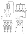
- the logic for the texture modulation calculator 39 is shown in Figure 11. This logic is also repeated three times, one for each of three independent texture stripe orientations and spacing.
- the actual texture modulation maps are contained in map memories 126, 128, 130 and 132. The maps for this configuration were chosen in the preferred embodiment of the invention to be 1024 depth with a selection of sixteen different maps total.
- the four bit texture map select code selects the one-of-sixteen map desired.
- the modulation maps are normally loaded through a test bus prior to an actual flight simulation run. Each of the three texture paths can have independent map modulations so that a large variety of patterns may be obtained in the three texture path summation. Each map is 8-bits wide so that a total of 256 modulation values may be defined for each texture stripe.
- the maps are stored with ten different levels of details (LOD) as part of an antialiasing scheme. Each successive LOD is an average of the previous more detailed level. The most detailed map of 1024 stripes is LOD 0. The next level, LOD 1, contains 512 stripes, and so forth all the way to LOD 10 which contains only one modulation value. As a simulation view point grows more distant from a textured surface, a smooth blend between a map's LOD levels is generated to prevent scintillation at the displayed pixel locations.
- LOD levels of details
- the LOD map selection and blend control is calculated from the floating point pattern gradients 110.
- the absolute value of the AP j and AP, gradients are compared to select the largest.
- One half the absolute value of the smaller gradient is then added to the absolute value of the larger gradient to obtain the ⁇ P max gradient.
- This calculation will approximate the diagonal maximum gradient which will be rotationally invariant, preventing a change in a map's LOD as the pattern's view point is rotated.
- the maximum gradient is then used to obtain the map LOD value and a 4-bit alpha (a) term which represents the relative view point position between two different map LODs.
- the 4-bit LOD number is generated by adder 112 and is defined to be the map LOD level which insures that no more than one texture modulation change occurs within a four element by four line pixel group.
- the locus of pixels at which the modulation change occurs is called a texture edge.
- each map requires storage of 1024 bytes (8-bits of word width for each location) for the highest resolution level.
- Each coarser map LOD requires a factor of two less storage as follows:
- the map storage is arranged so that the computed map LOD n and the next coarser LOD n+1 is available simultaneously so that a smooth blend between LODs may be accomplished in one system clock period. This requirement is met by having the map storage broken up into separate memories A and B as follows:
- memory A and B alternate lower and upper map portions depending on what LOD is being addressed. This alternation is controlled in the map address shift 114 by tri-stating either the LOD n or LOD n+1 output to the A or B memory boards depending upon the least significant bit (LSB) of the LOD number.
- the address shift is controlled by the LOD number.
- the address bits are shifted to select the different LOD levels within a map memory as follows:
- Texture edge smoothing is provided by calculating the area subtended to the right of the texture edge for each of the four pixels. This calculation is accomplished first by shifting the upper corner pattern address value (PI) and the two pattern gradients ( ⁇ P J , ⁇ P l ) by the 4-bit LOD number control in registers 116, 118 and 120, respectively. This information is sufficient to then determine the slope and position of the texture edge. The areas subtended by the individual pixels can then be determined based upon the geometry of the texture edge crossing. This calculation is handled by preprogrammed PROM firmware 138. The PROMs also determine the address for the right texture map by selecting either a ⁇ 1.0 addition in adders 122 and 124.
- Smooth LOD blending is provided between the first and next LOD texture map by the following calculation performed in units 134 and 136: This calculation is performed separately for the left texture map in 134 and for the right texture map in 136. Texture edge smoothing is performed in units 140, 142, 144 and 146 for the four pixels using the following formula:
- the shading computer 40 which does the three pattern texture combination and shading is shown in Figure 12.
- Three multiplexers 156,158 and 160 are used to select the particular texture pattern combination Pn which will be used on the face being processed.
- the three texture modulations are first scaled by one, two or three in dividers 150, 152 and 154 before being summed in the adders of summer 162. This prescaling of the modulations is used to prevent overflow after pattern summation.
- the modulations are then routed through translation maps 164 which can add special effects to the summed patterns. These maps have the texture modulation from summer 162 connected to the address input to the maps. Thus, any desirable pattern transformation can be applied to the modulation. If a map has the current address stored at each memory location, then no transformation will take place. Any desired deviation can be applied starting from this basis. There are a total of sixteen different transformation maps selectable using the 4-bit translation map select inputs.
- the shading modulation is obtained by the linear interpolation of the 20-bit fixed point pattern numbers P1, J and P l,J4 obtained from adders 98 and 100. This interpolation is performed in adders 166, 168 and 170 by a simple sum and divide by a two shift operation between the p ⁇ , J left side pattern value and the P l,J4 right side pattern value. Logic similar to adders 166, 168 and 170 constitutes the shading computer 41.
- the selection of shading, texture or no modulation for a display face is made by the multiplexers 172, 174, 176 and 178.
- the modulation outputs are used to vary an object's normal face color to some other value. This change is performed by multiplying the existing face color by the modulation outputs. Selection logic is included to modulate any combination of the red, green or blue component of the face color so that either monochrome or color modulation may be obtained.
Description
- The present invention generally relates to computer image generation (CIG) systems that produce images in "real time" for visual training simulators, and more particularly to a low cost, true-perspective texture/shading processor for raster graphics.
- The principle application area for CIG has been that of visual training simulators which present scenes to an observer or trainee to allow the observer to practice some task, such as flying an airplane. In a flight simulator, a three-dimensional model of the desired "gaming area" is prepared and stored on magnetic disk or similar bulk storage media. This model is called the visual data base. The visual simulator combines an image generator with an electro-optical display system such as a cathode ray tube (CRT) or similar display. The image generator reads in blocks of three-dimensional data from the disk and transforms this data into two-dimensional scene descriptions. A single simulator may be required to provide several different scenes, as, for example, in the case of an airplane having several windows in the cockpit. The two-dimensional data are converted to analog video that is presented to the operator via the display. The generated imagery is meant to be representative of the true scenes that the operator would see if the operator were actually performing the task being simulated. The generation of the display images is said to be in "real time" which is normally taken to mean 30 frames per second, as in the U.S. television standard. CIG systems are described in detail in the book entitled Computer Image Generation edited by Bruce J. Schachter and published by Wiley-Interscience (1983). In this context reference is also made to an earlier publication of Bruce J. Schachter: "Real Time Display of Textures", Proceedings of the 5th International Conference on Pattern Recognition, Florida, 01-04 December 1980, Vol. 2, pages 789 to 291, IEEE, New York, US. This paper relates to an image generation system for generating textured surfaces in real time. The operations are carried out by three cycles (Frames I, II, III) which are connected serially.
- US 3 999 308 relates to an image generator including texture/shading generator means which processes the texture portion of the data to activate face areas on a CRT display.
- Absolute realism is not achieved in CIG systems, but fortunately the training mission can be accomplished satisfactorily despite this apparent drawback. Recent developments have, moreover, remarkably improved the degree of realism attainable. Among the factors affecting the design of visual systems are texture and shading. Natural scenes are rich in texture, and the human eye relies heavily on texture cues to perceive the structure of a scene. In a flight simulator, suitable texture is required to create the visual sensations of air speed, altitude, horizon angle, and location in the environment. From a scene- processing point of view, the addition of texture to the displayed faces, i.e. planar portions of a modeled surface of the simulated scene, increases the information content without increasing the number of faces to be processed.
- When a face is illuminated by both direct sunlight and ambient light, there are in general three components of the surface illumination; ambient (such that a point has the same brightness at every angle of observation), specular reflection (such that the angle of reflection equals the angle of incidence for a perfect reflector and the amount of reflection reaching the eye if the reflector is imperfect is related to some power of the cosine of the angle between direction of reflection and the line of sight), and diffuse reflection (reflected from a given point equally in all directions but proportional to the cosine of the angle between the light source and the reflecting surface). Visual simulators do not generally display the specular component. It has been shown that the appearance of a diffuse-reflecting curved surface can be given to planar faces by performing a linear interpolation of the intensity values (or "shading values") of the vertices of the polygons that define the planar faces. The hardware required to do this in real time is extensive and, as a result, the effect is used sparingly in actual systems.
- It is therefore an object of the present invention to provide a low cost, true-perspective texture/shading processor for a raster graphics display that radically reduces the required storage and computation required both to generate and to process the digital data base.
- It is another object of the invention to provide a realistic computer-generated, three-dimensional raster graphics system but at a substantially reduced cost when compared to prior art systems.
- The objects of the invention are attained by the development of a mathematical model which defines modulations globally over the entire simulated, visual environment yet still provides correct, true-perspective computation of the face modulations in the raster image. This global mathematical model is generated, stored and processed using a much smaller amount of digital hardware. The basic innovation which achieves this reduction in hardware, and therefore cost, is the use of texture and shading gradients defined in three-dimensional space, instead of in each face plane, to define the texture and shading modulations. Three gradients are used. For shading, one gradient is used for each axis of the coordinate system in which the visual environment is modeled. Each gradient defines the manner in which a unit vector normal to the modeled surface varies in the direction of the corresponding axis. One set of gradients is used for each shaded object. For texturing, which is applied to the ground surface, all three gradients are defined in a nominal, flat ground plane. Each gradient defines a parallel series of planes of equal intensity. For each gradient, a reference point and reference value are also defined. The gradients define the variation of the surface normal or the texture stripe number relative to the reference value.
- The hardware savings of this approach is achieved by the fact that only one set of gradients and reference values is required for each shaded object and for each texture pattern on the ground surface. Previous systems have required that different gradients and reference values be defined for each shaded or textured polygon face. Each set of gradients and reference value requires proportional amount of processing to generate and to be transformed into the viewer's coordinate system. Hardware costs are generally reduced in proportion to the reduction in processing and storage.
- The foregoing and other objects, aspects and advantages of the invention will be better understood from the following detailed description of the invention with reference to the accompanying drawings, in which:
- Figure 1 is a functional block diagram showing the basic CIG system in which the subject invention is incorporated;
- Figure 2 is a more detailed block diagram of the CIG system showing the texture generator according to the invention;
- Figure 3 is a two-dimensional representation of the intersection of a terrain surface with texture planes;
- Figure 4 is a three-dimensional representation of the intersection of parallel, equally-spaced texture planes with the plane of a face to define parallel texture stripes; and
- Figure 5 is a three-dimensional representation of the intersection of parallel, equally-spaced shading planes with an object to define contours of equal shading normals;
- Figure 6 is a graphical illustration of the manner in which the mapping of the line numbers and pixel numbers is accomplished;
- Figure 7 is a block diagram of the texture/shading generator according to the invention;
- Figure 8 is a diagram illustrating the subdivision of a raster line into pixels and pixel groups;
- Figure 9 is a block diagram of the
distance calculators - Figure 10 is a block diagram of
base number calculators - Figure 11 is a block diagram of
texture computer 39 of the texture/shading generator shown in Figure 7; and - Figure 12 is a block diagram of shading
computer 40 of the texture/shading generator shown in Figure 7. - The basic CIG system in which the subject invention is incorporated consists of three major components termed Frame I, Frame II and Frame III. The "Frame i" designation refers to groupings of functions that were alloted one frame time (i.e., 1/30 seconds) for computation. The entire process therefore required three frame times from start to finish. While these conditions no longer hold true in general, the terms are still useful for identification purposes. Figure 1 shows the overall functional diagram of the CIG system. Frame I computations are normally performed in a minicomputer with a large magnetic disk storage. In this frame, the position of the viewpoint and any moving models, such as other aircraft, are determined in a common coordinate system. The principal function performed by Frame I is to manage the data base transferring data from disk storage to the active environment storage in Frame II to provide the subsequent processing with a description of the surrounding environment. Frame I also generates trigonometric coefficients required for perspective transformation and performs system executive functions such as, for example, maintenance.
- Frame II is part of a special-purpose computer. The function of Frame II can be thought of as reducing a three-dimensional description of the environment to a two-dimensional description for each viewing window. Frame II contains a rather large active-environment store that provides the data necessary to generate the scene from the viewpoint location. The active-environment storage is accessed by Frame II to obtain only that data that describes the scene as viewed through the view window of each display channel. The data undergoes a perspective correction to transform it into the coordinates of each view window. The data receives a channel assignment that will be used later to route it to the proper display channel. Frame II also assigns a priority to each surface in the scene. The priorities are assigned so that surfaces closer to the viewpoint have a higher priority than more distant surfaces. These priorities are used in subsequent processing to determine which surface should be displayed when one object is occulted by another.
- Frame III essentially has the function of reducing the two-dimensional representation of a scene to a scan line or a one-dimensional representation. Frame III is broken into two halves: Frame IIIA, which serves all display channels, and Frame IIIB, which is replicated for each display channel. Frame IIIA generates edge data from the vertex desgination used in earlier processing. This edge data locates where the edge crosses a scan line, describes the characteristics of the surface to the right of the edge, and is generated for each scan line crossing the edge. After the edge data is ordered, the priority data is used to eliminate edge data for hidden surfaces.
- Frame IIIB processes the lists of edge crossings it receives to generate video for the displays. It performs an edge smoothing to eliminate undesirable quantization effects, performs curved-surface shading, and generates texture for surfaces that are to receive a texture pattern. The computations required in Frame IIIB are relatively straight forward but must be performed at very high pixel rates (30―40 MHz) which accounts for the usually high costs of this subsystem. More specifically, the computation of face modulation in previous CIG systems has required that different patterns be stored for each face in a digital data base and that these patterns be processed separately for each face. This has required large storage and computational hardware. The present invention, however, is an improvement to this subsystem that radically reduces the required storage and computation and therefore greatly reduces the costs of the subsystem. This reduction is accomplished by the development of a mathematical model which defines the modulations globally over the entire simulated, visual environment, yet still provides correct, true-perspective computation of the face modulations in the raster image. This global math model is generated, stored, and processed using a much smaller amount of digital hardware.
- The display subsystem consists of either a CRT or light valve projector to produce an image from the video. The display subsystem includes some optics designed to place the image at infinity relative to the viewpoint.
- Figure 2 is functional block diagram of the CIG system of Figure 1 drawn to emphasize
face modulation processing 13 and the texture/shading generator 16 of the present invention. Adisk storage 10 contains the visual data base (VDB) that is supplied to Frames I and II. Frame I loads inprocessor 12 the environment data blocks (EDB's) of the VDB, describing the geometry of the data base to vertex, face/edge, color, and priority processing.Processor 12 is part of Frame II. Frame I also supplies toprocessor 12 dynamic data in the form of a viewpoint vector V relative to the environment coordinate system and a direction cosine matrix [DC]VP ENV to rotate the environment from its coordinate set (x, y, z) into that of the view point (u, v, w). Frame II uses this data to perform a perspective mapping of the face edges of the environment into the view plane. This edge data is sent to theedge generator 14 of Frame III which computes the intersections (edge-crossings) of the edges with each raster line and orders these by element number. The ordered edge crossings, together with face priority and color data are used by thepriority resolver 15 to eliminate hidden edges. Thepriority resolver 15 supplies to thevideo processor 17 an ordered list of edge crossings with pixel area and color data. The texture/shading generator 16 generates texture, shading and fading modulation data for up to three face areas in each of four pixels during every 120 ns. logic clock interval. The texture modulation values are between 0.0 and 2.0 and may be different for each pixel. The fading modulation values F are between 0.0 and 1.0 and are identical for the four pixels. Thevideo processor 17 applies the texture and fading modulations to each of the three face areas per pixel according to the followinq equation:
- C is the computed pixel color (red, green or blue),
- Ap is the point feature area,
- A are the face areas where i=1, 2 or 3,
- T is 1 or TA or TB based on the texture select code, where TA is the last face texturing or shading modulation to be updated and TB is the next-to-last face shading modulation to be updated,
- F, is 1 or FSG or FA or FB'
- FSG is sky or ground fading per pixel,
- FA is the last face fading value to be updated,
- FB is the next-to-last fading value updated,
- C is the face color associated with area i,
- CH is the haze color, and
- Cp is the point feature color.
- While it should be understood that texture is a modulation of a face in the form of a series of parallel stripes of varying intensities, a brief digression at this point should serve to place the subject invention in proper perspective. In early CIG systems, individual edges would have been used to model the boundaries of each stripe. However, if the stripes are equally spaced and parallel, they can be specified and processed in a much more economical way. A single gradient vector in the plane of the face can indicate the spacing and orientation of the series of stripes. A modeler defines texture by specifying from one to three gradients in the plane of each textured face. In addition to these gradients, a texture map number and a starting point for the map are assigned to each gradient to indicate the modulation values associated with each stripe. This method allows each face to be textured differently without subdividing the faces into edges; however, it still requires about 45 bytes of data to define the gradients, start values, and texture map codes for each different texture. The storage and processing of this data are comparable to the storage and processing for about four edges per face. For very large faces, this provides an economical reduction compared to processing every texture edge independently. Further reductions in memory. and computations are still needed to provide truly low-cost systems.
- In most applications of texture, it is desirable to extend a single texture pattern over a number of adjacent faces. For example, if a forest texture covers portions of several contiguous terrain faces, the texture should flow from one face to the next without any discontinuities, since such discontinuities would tend to accentuate the boundaries of the individual terrain faces. This is even more important for "regular" textures such as those used to represent plowed fields or orchards.
- The present invention allows a continuous texture pattern covering any number of faces to be specified by a single set of gradients, start values and map codes. This method not only reduces data storage requirements, but it also eliminates the need to project gradients independently for each face. Finally, because the texture for all faces representing the same type of surface is specified by a single set of data, it is easy to modify a texture, whether to improve its appearance, to correct a modeling error, or to simulate motion of a surface, e.g. flowing water.
- The basic innovation which achieves this reduction in cost is the use of planes defined in three-dimensional space, instead of stripes in each face plane, to define the texture or shading modulation. This concept is illustrated in Figures 3 and 4 where a face is divided into texture stripes by a series of parallel texture planes. The same stripes could be defined by planes oriented at a different angle to the plane of the face, as long as the lines of intersection are held constant. A series of parallel planes, just as a series of parallel lines, can be specified by an orthogonal gradient whose length is proportional to the spacing between the planes. The gradient need not be in the plane of the face. To show how this approach is used, consider a network of faces defining a terrain surface. Figure 4 shows a cross-section of such a terrain which is segmented by a series of texture planes. The texture planes are all orthogonal to a single gradient in a flat reference plane. These planes may cut across any number of faces. Where the intersections occur, texture stripes will be defined. These texture stripes have two important properties. First, they will match up at all face boundaries, assuring continuity of texture. Second, although their relative spacing will vary with the slope of each face, they will have a constant spacing in any x-y plane. This kind of geometry is expected for many types of features frequently represented by texture such as, for example, plowed furrows, fields, city blocks, or tree lines. Other textures, such as lines of bricks in a wall, might be defined by a series of horizontal planes. The same set of planes could be used for any wall with equally spaced bricks.
- Shading, like texturing, has been defined by gradients in the face plane. The shading gradients define the vector normal to any point on an object surface. However, this vector normal, much like the texture stripes, should match at each edge of an object in order to create the appearance of smoothness of the surface at that edge. Therefore, a single set of gradients can be defined for each shaded object of the visual environment model. This is illustrated in Figure 5.
- The present invention computes the point on each textured/shaded face onto which each pixel of the image raster falls when it is inverse perspectively mapped from the view plane into the visual environment. It then determines the location of this point relative to the parallel planes defining the texturing or shading pattern. The mathematics by which this mapping is computed is as follows. The planes defining either a texture or a shading pattern can be defined by the locus of points in the environment satisfying the following equation:

- Pa is the pattern value at point a,
- Po is the pattern value at a reference point,
- KpN is the gradient vector defining the rate of change of P, and
- V:a is the vector from the reference point to the point a.
- Because texturing and shading are applied in Frame III to each pixel of each textured/shaded face, it is necessary to compute the point in space corresponding to each pixel (I, J), where I is the line number and J is the pixel number. The manner in which this mapping is computed is illustrated in Figure 6. This figure shows a cross section of the u-w plane in viewer space. The intersection of the view plane and of the face with the u-w plane are shown with bold lines. The line number I of the viewer raster increases from top to bottom in the view plane. To find the coordinates u and w of the point a on the faces, first u and then w/u are computed.
- The coordinate u is the distance along an orthogonal to the view plane from the view point to point a. From the figure,


- The ratio w/u is just Cw(I-lo), while v/u is just Cv(J-Jo). Thus, the (u, v, w) components of point a are


- The computation can be simplified by grouping those terms which are constant for a given face or pattern:


- The computation which must then be performed on a pixel-by-pixel basis is as follows:

- The present invention includes
face modulation processor 13, which is added to Frame II and computes the face and pattern coefficients, and the texture/shading generator 16, which is added to Frame III and computes the texturing and/or shading modulation on a pixel-by-pixel basis. Because the operations offace modulation processor 13 are greatly simplified by the math model for textu ring/shading of the present invention, these operations are performed using the existing Frame I general purpose computer and Frame II arithmetic pipelines of the basic image generator. Therefore, the only added hardware unit is the texture/shading generator 16. The texture/shading generator 16 computes, for every group of four pixels, the inverse perspective mapping of that group onto the surface of one or two incident faces. From this mapping, it computes either a shading modulation or a texture modulation for each face at each of the four pixels of the group. - Figure 7 is a block diagram of the texture/shading generator. The texture/shading generator receives data in three ping-
pong memories face modulation processor 13 and stored in thepattern memory 30. Data describing the plane of each textured or shaded face is also received every field time and is stored in the face memory 31. Finally, for every raster line of the field, data describing each edge is received from thepriority resolver 15 and stored in theedge memory 32. The two sides of thepattern memory 30 and the face memory 31 are exchanged every field time such that data for the field currently being displayed is being read out while data for the next field is being written. The two sides of theedge memory 32 are alternated every raster line time such that data for the line currently being displayed is being read out while data for the next line is being written. - Figure 8 illustrates the subdivision of a raster line into pixels and pixel groups. Texturing/shading is computed for four pixels at a time in order to achieve high resolution video rates (approximately 25 to 30 MHz). One pixel group is computed every 120 ns. The basic operation of the texture/shading is to map each four-pixel group into one shading modulation for one or two faces or into one, two, or three texture stripe maps for one face. Two shaded faces are computed if an edge between two shaded faces appears in the four-pixel group. If there are more than one textured or two shaded faces in the group, then one or more face modulations are approximated by the value 1.0 or by the Face A or Face B modulation. The requirement to calculate two shaded faces while only one textured face can be computed is imposed because it is more important to avoid discontinuities in a shaded surface than in a textured surface.
- The calculations of the texture generator are performed in a pipelined manner and during any given clock time, several pixel groups may be in various stages of processing. It is convenient to consider the operations performed on one pixel group as it sequences through the stages of the pipeline. First, edge data is read from the
edge memory 32. This data includes the element-value JL of a new edge to be processed, the face number to be used for new texture/shading calculations for that pixel group, and a "hold flag". The hold flag indicates that data for the current face is to be retained for shading path "B" computations in the next pixel group. The face number read from theedge memory 32 is used to address face data in the face memory 31 which is stored by face number. The denominator coefficients C4, CS and C6 are used for distance computation incalculators pattern memory 30 and to select the appropriate texture maps for texture computation. - A Frame I data register 33 stores the line and element number of the pixel at the orthogonal to the view plane. These are used by
edge crossing control 34 to compute a relative line number (I-lo) and element number (J-Jo) from the element-value JL and current line I. -
Calculators 
distance calculators base number calculators Base number calculator 37 maps the upper left corner of the pixel group into three texture stripe numbers or one shading modulation value for Face A. It also computes the change in stripe number over four elements (APj) or over four lines (ΔP1) for each of the three texture patterns and computes the shading modulation value at the upper right corner of the pixel group.Base number calculator 38 computes the shading modulation at the upper left and upper right corners of the pixel group for Face B, a previous face identified by the hold flag. The formulas are as follows: - Upper Left: Pi,j=ui,j[C1+C2(l-lo)+C3(J-Jo)]+Pr
- Bottom Left: P14,j=U14,J[C1+C2(l+4-lo)+C3(J-Jo)]+P1
- Upper Right: Pl,J4=ul,J4[C1+C2(l-lo)+C3(J+4-Jo)]+Pr
- Four Element Change: ΔPJ=Pl,J4-Pl-J, and
- Four Line Change: ΔPl=Pl4,J-Pl,J,
where - 14=1+4 and J4=J+4.
- Figure 9 shows the
distance calculation multiplier 50 by the 14-bit I-lo four pixel group line location.Multiplier 50 comprises 16-bit multiplier and exponent adder integrated circuits (ICs). The C6 coefficient is multiplied inmultiplier 52 by the 14-bit J-Jo four pixel group element location.Multiplier 52 is similar tomultiplier 50. The results of these multiplications are added inadders series expansion unit 58. The reciprocal is used to implement the hardware divide to allow a multiply operation instead of the more difficult divide operation. - The distance calculation for the four line position is obtained by adding four times the C5 coefficient to the Dl,J result in
adder 60. Similarly, the distance calculation for the four element position is obtained by adding four times the C6 coefficient to the D,,j result inadder 62. The reciprocal for these two locations is also taken infirmware units - The numerator calculation is shown in Figure 10. This is the
base number calculator 37 and is repeated three times for the three independent texture stripes to be calculated. Thebase number calculator 38 comprises similar logic. The C2 coefficient is multiplied inmultiplier 72 by the 14-bit I-lo four pixel group line location using 16-bit multiplier and exponent adder ICs. The C3 coefficient is multiplied inmultiplier 74 by the 14-bit J-Jo four pixel group element location. The result is then added inadders 76 and 78 to the C1 starting coefficient using floating point ALU ICs. The result is the numerator term for the I,J (Nl,J) element position of the four pixel group. - The numerator calculation for the four line position is obtained by adding four times the C2 coefficient to the Nl,J result in
adder 80. Similarly, the numerator calculation for the four element position is obtained by adding four times the C3 coefficient to the Nl,J result inadder 82. The N/D hardware divide for the three terms is calculated by multiplying the reciprocal of the denominator obtained fromfirmware units exponent adder ICs converter 90 and then adding the Pt offset with fixedpoint adder 98. The fixed point version of the P number for the I,J4 pixel position is similarly taken withconverter 94 andadder 100. The pattern gradient in the element direction is calculated with floatingpoint ALU 96, and the pattern gradient in the line direction is calculated with floatingpoint ALU 92. - The logic for the
texture modulation calculator 39 is shown in Figure 11. This logic is also repeated three times, one for each of three independent texture stripe orientations and spacing. The actual texture modulation maps are contained inmap memories - The maps are stored with ten different levels of details (LOD) as part of an antialiasing scheme. Each successive LOD is an average of the previous more detailed level. The most detailed map of 1024 stripes is
LOD 0. The next level,LOD 1, contains 512 stripes, and so forth all the way toLOD 10 which contains only one modulation value. As a simulation view point grows more distant from a textured surface, a smooth blend between a map's LOD levels is generated to prevent scintillation at the displayed pixel locations. - The LOD map selection and blend control is calculated from the floating point pattern gradients 110. The absolute value of the APj and AP, gradients are compared to select the largest. One half the absolute value of the smaller gradient is then added to the absolute value of the larger gradient to obtain the ΔPmax gradient. This calculation will approximate the diagonal maximum gradient which will be rotationally invariant, preventing a change in a map's LOD as the pattern's view point is rotated. The maximum gradient is then used to obtain the map LOD value and a 4-bit alpha (a) term which represents the relative view point position between two different map LODs. The 4-bit LOD number is generated by
adder 112 and is defined to be the map LOD level which insures that no more than one texture modulation change occurs within a four element by four line pixel group. The locus of pixels at which the modulation change occurs is called a texture edge. - In the preferred embodiment, each map requires storage of 1024 bytes (8-bits of word width for each location) for the highest resolution level. Each coarser map LOD requires a factor of two less storage as follows:

- The map storage is arranged so that the computed map LOD n and the next coarser LOD n+1 is available simultaneously so that a smooth blend between LODs may be accomplished in one system clock period. This requirement is met by having the map storage broken up into separate memories A and B as follows:

- Note that memory A and B alternate lower and upper map portions depending on what LOD is being addressed. This alternation is controlled in the
map address shift 114 by tri-stating either the LOD n or LOD n+1 output to the A or B memory boards depending upon the least significant bit (LSB) of the LOD number. The address shift is controlled by the LOD number. The address bits are shifted to select the different LOD levels within a map memory as follows:
- There are two duplicate map copies provided; one for the modulation to the left side of the texture edge crossing and one for the modulation to the right side of the texture edge crossing. Texture edge smoothing is provided by calculating the area subtended to the right of the texture edge for each of the four pixels. This calculation is accomplished first by shifting the upper corner pattern address value (PI) and the two pattern gradients (ΔPJ, ΔPl) by the 4-bit LOD number control in
registers PROM firmware 138. The PROMs also determine the address for the right texture map by selecting either a ±1.0 addition inadders - Smooth LOD blending is provided between the first and next LOD texture map by the following calculation performed in
units 134 and 136:
units 
- The
shading computer 40 which does the three pattern texture combination and shading is shown in Figure 12. Three multiplexers 156,158 and 160 are used to select the particular texture pattern combination Pn which will be used on the face being processed. The three texture modulations are first scaled by one, two or three individers summer 162. This prescaling of the modulations is used to prevent overflow after pattern summation. The modulations are then routed throughtranslation maps 164 which can add special effects to the summed patterns. These maps have the texture modulation fromsummer 162 connected to the address input to the maps. Thus, any desirable pattern transformation can be applied to the modulation. If a map has the current address stored at each memory location, then no transformation will take place. Any desired deviation can be applied starting from this basis. There are a total of sixteen different transformation maps selectable using the 4-bit translation map select inputs. - The shading modulation is obtained by the linear interpolation of the 20-bit fixed point pattern numbers P1,J and Pl,J4 obtained from
adders adders adders shading computer 41. The selection of shading, texture or no modulation for a display face is made by themultiplexers - From the foregoing description of the preferred embodiment of the invention, it will be appreciated that a minimum amount of hardware is required to implement the true-perspective texture/shading processor according to the invention. This is accomplished by specifying a single set of gradients, start values and map codes to define a continuous texture pattern covering any number of faces. This eliminates the need to project gradients independently for each face thereby reducing both storage and processing requirements.
A given value of P defines a plane in space which is parallel to the plane defined by any other value of P. The terms P. and Kp
Claims (10)
Applications Claiming Priority (2)
| Application Number | Priority Date | Filing Date | Title |
|---|---|---|---|
| US560147 | 1983-12-12 | ||
| US06/560,147 US4586038A (en) | 1983-12-12 | 1983-12-12 | True-perspective texture/shading processor |
Publications (3)
| Publication Number | Publication Date |
|---|---|
| EP0144924A2 EP0144924A2 (en) | 1985-06-19 |
| EP0144924A3 EP0144924A3 (en) | 1985-08-21 |
| EP0144924B1 true EP0144924B1 (en) | 1990-09-19 |
Family
ID=24236571
Family Applications (1)
| Application Number | Title | Priority Date | Filing Date |
|---|---|---|---|
| EP84114506A Expired - Lifetime EP0144924B1 (en) | 1983-12-12 | 1984-11-29 | True-perspective texture/shading processor |
Country Status (5)
| Country | Link |
|---|---|
| US (1) | US4586038A (en) |
| EP (1) | EP0144924B1 (en) |
| JP (1) | JPS60140476A (en) |
| DE (1) | DE3483246D1 (en) |
| IL (1) | IL73789A0 (en) |
Cited By (1)
| Publication number | Priority date | Publication date | Assignee | Title |
|---|---|---|---|---|
| CN108235138A (en) * | 2016-12-15 | 2018-06-29 | 宏达国际电子股份有限公司 | Method, processing unit and its computer system of preview video |
Families Citing this family (147)
| Publication number | Priority date | Publication date | Assignee | Title |
|---|---|---|---|---|
| GB8320357D0 (en) * | 1983-07-28 | 1983-09-01 | Quantel Ltd | Video graphic simulator systems |
| US4901252A (en) * | 1984-07-13 | 1990-02-13 | International Business Machines Corporation | Method for producing planar geometric projection images |
| US4821212A (en) * | 1984-08-08 | 1989-04-11 | General Electric Company | Three dimensional texture generator for computed terrain images |
| US4715005A (en) * | 1984-08-08 | 1987-12-22 | General Electric Company | Terrain/seascape image generator with math model data base |
| JPH0746391B2 (en) * | 1984-09-14 | 1995-05-17 | 株式会社日立製作所 | Graphic seeding device |
| US4780711A (en) * | 1985-04-12 | 1988-10-25 | International Business Machines Corporation | Anti-aliasing of raster images using assumed boundary lines |
| US4737921A (en) * | 1985-06-03 | 1988-04-12 | Dynamic Digital Displays, Inc. | Three dimensional medical image display system |
| CA1283738C (en) * | 1985-11-13 | 1991-04-30 | Atsushi Hasebe | Data processor |
| US5239628A (en) * | 1985-11-13 | 1993-08-24 | Sony Corporation | System for asynchronously generating data block processing start signal upon the occurrence of processing end signal block start signal |
| US4692880A (en) * | 1985-11-15 | 1987-09-08 | General Electric Company | Memory efficient cell texturing for advanced video object generator |
| JPS62200394A (en) * | 1986-02-28 | 1987-09-04 | 横河メデイカルシステム株式会社 | Image display unit |
| FR2597227B1 (en) * | 1986-04-14 | 1992-09-11 | Pixar | METHOD FOR PRODUCING A TWO-DIMENSIONAL DISPLAY REPRESENTING A THREE-DIMENSIONAL DATA SET |
| US4805116A (en) * | 1986-04-23 | 1989-02-14 | International Business Machines Corporation | Interpolated display characteristic value generator |
| GB8613447D0 (en) * | 1986-06-03 | 1986-07-09 | Quantel Ltd | Video image processing systems |
| US4928250A (en) * | 1986-07-02 | 1990-05-22 | Hewlett-Packard Company | System for deriving radiation images |
| US5283859A (en) * | 1986-09-03 | 1994-02-01 | International Business Machines Corporation | Method of and system for generating images of object transforms |
| JPH0812705B2 (en) * | 1986-09-29 | 1996-02-07 | 株式会社東芝 | Image processing device |
| US5001651A (en) * | 1986-11-10 | 1991-03-19 | Auto-Trol Technology Corporation | Method and apparatus for interpolating groups of pixels on a scan line |
| GB2207585B (en) * | 1987-07-27 | 1992-02-12 | Sun Microsystems Inc | Method and apparatus for shading images |
| US4888712A (en) * | 1987-11-04 | 1989-12-19 | Schlumberger Systems, Inc. | Guardband clipping method and apparatus for 3-D graphics display system |
| US4901064A (en) * | 1987-11-04 | 1990-02-13 | Schlumberger Technologies, Inc. | Normal vector shading for 3-D graphics display system |
| US4945500A (en) * | 1987-11-04 | 1990-07-31 | Schlumberger Technologies, Inc. | Triangle processor for 3-D graphics display system |
| US4885703A (en) * | 1987-11-04 | 1989-12-05 | Schlumberger Systems, Inc. | 3-D graphics display system using triangle processor pipeline |
| US4974176A (en) * | 1987-12-18 | 1990-11-27 | General Electric Company | Microtexture for close-in detail |
| JP2618951B2 (en) * | 1988-02-16 | 1997-06-11 | 株式会社東芝 | 3D graphics processor |
| US5128872A (en) * | 1988-12-20 | 1992-07-07 | Sun Microsystems, Inc. | Method and apparatus for determining line positions for display and manipulation by a computer system |
| US4998214A (en) * | 1989-04-03 | 1991-03-05 | Unisys Corp. | Apparatus for line imaging |
| US5265198A (en) * | 1989-10-23 | 1993-11-23 | International Business Machines Corporation | Method and processor for drawing `polygon with edge`-type primitives in a computer graphics display system |
| KR100232931B1 (en) * | 1989-12-21 | 1999-12-01 | 이데이 노부유끼 | A shading method and shading apparatus for computer graphics |
| GB2240016A (en) * | 1990-01-15 | 1991-07-17 | Philips Electronic Associated | Texture memories store data at alternating levels of resolution |
| US5224208A (en) * | 1990-03-16 | 1993-06-29 | Hewlett-Packard Company | Gradient calculation for texture mapping |
| EP0459761A3 (en) * | 1990-05-31 | 1993-07-14 | Hewlett-Packard Company | Three dimensional computer graphics employing ray tracking to compute form factors in radiosity |
| JPH0785219B2 (en) * | 1990-11-15 | 1995-09-13 | インターナショナル・ビジネス・マシーンズ・コーポレイション | Data processing system and data control method |
| JPH087715B2 (en) * | 1990-11-15 | 1996-01-29 | インターナショナル・ビジネス・マシーンズ・コーポレイション | Data processing device and access control method |
| US5420972A (en) * | 1990-11-15 | 1995-05-30 | International Business Machines Corporation | Method and apparatus for rendering lines |
| JPH0683969A (en) * | 1990-11-15 | 1994-03-25 | Internatl Business Mach Corp <Ibm> | Graphics processor and method of graphics and data processing |
| JP2725915B2 (en) * | 1990-11-15 | 1998-03-11 | インターナショナル・ビジネス・マシーンズ・コーポレイション | Triangle drawing apparatus and method |
| US5231499A (en) * | 1991-02-11 | 1993-07-27 | Ampex Systems Corporation | Keyed, true-transparency image information combine |
| US5214512A (en) * | 1991-02-11 | 1993-05-25 | Ampex Systems Corporation | Keyed, true-transparency image information combine |
| US5415549A (en) * | 1991-03-21 | 1995-05-16 | Atari Games Corporation | Method for coloring a polygon on a video display |
| EP0627103B1 (en) * | 1992-02-18 | 1996-01-10 | EVANS & SUTHERLAND COMPUTER CORPORATION | Image texturing system having theme cells |
| DE69226512T2 (en) * | 1992-03-12 | 1999-04-22 | Ibm | Image processing method |
| US5469535A (en) * | 1992-05-04 | 1995-11-21 | Midway Manufacturing Company | Three-dimensional, texture mapping display system |
| GB2267203B (en) * | 1992-05-15 | 1997-03-19 | Fujitsu Ltd | Three-dimensional graphics drawing apparatus, and a memory apparatus to be used in texture mapping |
| GB2268292A (en) * | 1992-06-16 | 1994-01-05 | Ibm | Error handling in a state-free system |
| JP2634126B2 (en) * | 1992-07-27 | 1997-07-23 | インターナショナル・ビジネス・マシーンズ・コーポレイション | Graphics display method and apparatus |
| US5550959A (en) * | 1993-05-27 | 1996-08-27 | Novalogic, Inc. | Technique and system for the real-time generation of perspective images |
| JPH0757117A (en) * | 1993-07-09 | 1995-03-03 | Silicon Graphics Inc | Forming method of index to texture map and computer control display system |
| JPH0778267A (en) * | 1993-07-09 | 1995-03-20 | Silicon Graphics Inc | Method for display of shadow and computer-controlled display system |
| US5625374A (en) * | 1993-09-07 | 1997-04-29 | Apple Computer, Inc. | Method for parallel interpolation of images |
| US5699497A (en) * | 1994-02-17 | 1997-12-16 | Evans & Sutherland Computer Corporation | Rendering global macro texture, for producing a dynamic image, as on computer generated terrain, seen from a moving viewpoint |
| US5649173A (en) * | 1995-03-06 | 1997-07-15 | Seiko Epson Corporation | Hardware architecture for image generation and manipulation |
| EP0751486B1 (en) * | 1995-06-30 | 2003-10-08 | Matsushita Electric Industrial Co., Ltd. | Method and apparatus for rendering and mapping images |
| US5877779A (en) * | 1995-07-06 | 1999-03-02 | Sun Microsystems, Inc. | Method and apparatus for efficient rendering of three-dimensional scenes |
| US6005580A (en) * | 1995-08-22 | 1999-12-21 | Micron Technology, Inc. | Method and apparatus for performing post-process antialiasing of polygon edges |
| EP0772119A3 (en) * | 1995-10-31 | 1997-12-29 | Cirrus Logic, Inc. | Automatic graphics operation |
| US6014472A (en) * | 1995-11-14 | 2000-01-11 | Sony Corporation | Special effect device, image processing method, and shadow generating method |
| US6108460A (en) * | 1996-01-02 | 2000-08-22 | Pixelfusion Limited | Load balanced image generation |
| US5808690A (en) * | 1996-01-02 | 1998-09-15 | Integrated Device Technology, Inc. | Image generation system, methods and computer program products using distributed processing |
| US5850489A (en) * | 1996-01-02 | 1998-12-15 | Integrated Device Technology, Inc. | Linear expression evaluator |
| US5892517A (en) * | 1996-01-02 | 1999-04-06 | Integrated Device Technology, Inc. | Shared access texturing of computer graphic images |
| US5831625A (en) * | 1996-01-02 | 1998-11-03 | Integrated Device Technology, Inc. | Wavelet texturing |
| US6104842A (en) * | 1996-06-10 | 2000-08-15 | Integrated Device Technology, Inc. | Geometry processing of digital video models and images |
| US5977982A (en) * | 1996-06-28 | 1999-11-02 | Avid Technology Inc. | System and method for modification of the visual characteristics of digital 3D objects |
| US5793386A (en) * | 1996-06-28 | 1998-08-11 | S3 Incorporated | Register set reordering for a graphics processor based upon the type of primitive to be rendered |
| US5936635A (en) * | 1996-06-28 | 1999-08-10 | Cirrus Logic, Inc. | System and method of rendering polygons into a pixel grid |
| US5844562A (en) * | 1996-06-28 | 1998-12-01 | Deneb Robotics, Inc. | Method for hi-fidelity graphic rendering of three-dimensional objects |
| US5828382A (en) * | 1996-08-02 | 1998-10-27 | Cirrus Logic, Inc. | Apparatus for dynamic XY tiled texture caching |
| US5875295A (en) * | 1996-09-30 | 1999-02-23 | S3 Incorporated | Instruction format for ensuring safe execution of display list |
| US5987582A (en) * | 1996-09-30 | 1999-11-16 | Cirrus Logic, Inc. | Method of obtaining a buffer contiguous memory and building a page table that is accessible by a peripheral graphics device |
| US6348917B1 (en) | 1996-09-30 | 2002-02-19 | Cirrus Logic, Inc | Dynamic switching of texture mip-maps based on depth |
| US5845874A (en) * | 1996-10-29 | 1998-12-08 | Silicon Graphics, Inc. | System and method for creating visual images of aircraft wake vortices |
| US5898438A (en) * | 1996-11-12 | 1999-04-27 | Ford Global Technologies, Inc. | Texture mapping of photographic images to CAD surfaces |
| US5878174A (en) * | 1996-11-12 | 1999-03-02 | Ford Global Technologies, Inc. | Method for lens distortion correction of photographic images for texture mapping |
| US6088016A (en) * | 1996-12-30 | 2000-07-11 | S3 Incorporated | Dithering method and apparatus using ramp probability logic |
| US5844576A (en) * | 1996-12-30 | 1998-12-01 | Cirrus Logic, Inc. | Tiled linear host texture storage |
| US5835097A (en) * | 1996-12-30 | 1998-11-10 | Cirrus Logic, Inc. | Non-homogenous second order perspective texture mapping using linear interpolation parameters |
| US5986663A (en) * | 1997-10-10 | 1999-11-16 | Cirrus Logic, Inc. | Auto level of detail-based MIP mapping in a graphics processor |
| US6157386A (en) * | 1997-10-10 | 2000-12-05 | Cirrus Logic, Inc | MIP map blending in a graphics processor |
| US6052127A (en) * | 1996-12-30 | 2000-04-18 | Cirrus Logic, Inc. | Circuit for determining non-homogenous second order perspective texture mapping coordinates using linear interpolation |
| US6333746B1 (en) | 1996-12-30 | 2001-12-25 | Cirrus Logic, Inc. | Auto level of detail texture mapping for a software graphics engine |
| US5841442A (en) * | 1996-12-30 | 1998-11-24 | Cirrus Logic, Inc. | Method for computing parameters used in a non-homogeneous second order perspective texture mapping process using interpolation |
| US5796385A (en) * | 1997-01-28 | 1998-08-18 | Integrated Device Technology, Inc. | Luminance controlled color resolution reduction |
| US5949426A (en) * | 1997-01-28 | 1999-09-07 | Integrated Device Technology, Inc. | Non-linear texture map blending |
| US5977983A (en) * | 1997-02-20 | 1999-11-02 | S3 Incorporated | Method and apparatus for adjusting graphics processing procedures based on a selectable speed/quality gauge |
| US5929869A (en) * | 1997-03-05 | 1999-07-27 | Cirrus Logic, Inc. | Texture map storage with UV remapping |
| US6072508A (en) * | 1997-03-14 | 2000-06-06 | S3 Incorporated | Method and apparatus for shortening display list instructions |
| US6028613A (en) * | 1997-03-20 | 2000-02-22 | S3 Incorporated | Method and apparatus for programming a graphics subsystem register set |
| US5949421A (en) * | 1997-03-31 | 1999-09-07 | Cirrus Logic, Inc. | Method and system for efficient register sorting for three dimensional graphics |
| US6130674A (en) * | 1997-03-31 | 2000-10-10 | Cirrus Logic, Inc. | Dynamically selectable texture filter for computer graphics |
| US5978895A (en) * | 1997-04-04 | 1999-11-02 | Cirrus Logic, Inc. | Method for speeding mathematical operations in a processor core |
| US6020893A (en) * | 1997-04-11 | 2000-02-01 | Novalogic, Inc. | System and method for realistic terrain simulation |
| US5835104A (en) * | 1997-04-23 | 1998-11-10 | S3 Incorporated | Variable band size compositing buffer method and apparatus |
| US5940090A (en) * | 1997-05-07 | 1999-08-17 | Cirrus Logic, Inc. | Method and apparatus for internally caching the minimum and maximum XY pixel address values in a graphics subsystem |
| US6266753B1 (en) | 1997-07-10 | 2001-07-24 | Cirrus Logic, Inc. | Memory manager for multi-media apparatus and method therefor |
| US6054993A (en) * | 1997-09-17 | 2000-04-25 | Cirrus Logic, Inc. | Chroma-keyed specular texture mapping in a graphics processor |
| US6181347B1 (en) | 1997-09-17 | 2001-01-30 | Cirrus Logic, Inc. | Selectable mode smoothing texture filter for computer graphics |
| US6111583A (en) | 1997-09-29 | 2000-08-29 | Skyline Software Systems Ltd. | Apparatus and method for three-dimensional terrain rendering |
| US6002409A (en) * | 1997-10-29 | 1999-12-14 | Cirrus Logic, Inc. | Arbitration for shared graphics processing resources |
| US7136068B1 (en) | 1998-04-07 | 2006-11-14 | Nvidia Corporation | Texture cache for a computer graphics accelerator |
| US6259455B1 (en) | 1998-06-30 | 2001-07-10 | Cirrus Logic, Inc. | Method and apparatus for applying specular highlighting with specular components included with texture maps |
| US6252606B1 (en) | 1998-06-30 | 2001-06-26 | Cirrus Logic, Inc. | Error correction in a graphics processor |
| CN1159682C (en) * | 1998-11-12 | 2004-07-28 | 索尼电脑娱乐公司 | Image generation method and image generation device |
| US6362824B1 (en) | 1999-01-29 | 2002-03-26 | Hewlett-Packard Company | System-wide texture offset addressing with page residence indicators for improved performance |
| US20030158786A1 (en) * | 1999-02-26 | 2003-08-21 | Skyline Software Systems, Inc. | Sending three-dimensional images over a network |
| US6919895B1 (en) | 1999-03-22 | 2005-07-19 | Nvidia Corporation | Texture caching arrangement for a computer graphics accelerator |
| US6181352B1 (en) | 1999-03-22 | 2001-01-30 | Nvidia Corporation | Graphics pipeline selectively providing multiple pixels or multiple textures |
| US6606089B1 (en) | 1999-06-08 | 2003-08-12 | Sulzer Market And Technology Ag | Method for visualizing a spatially resolved data set |
| EP1059612A1 (en) * | 1999-06-08 | 2000-12-13 | Sulzer Markets and Technology AG | Spatially-defined data visualization method |
| US6717577B1 (en) | 1999-10-28 | 2004-04-06 | Nintendo Co., Ltd. | Vertex cache for 3D computer graphics |
| US6618048B1 (en) | 1999-10-28 | 2003-09-09 | Nintendo Co., Ltd. | 3D graphics rendering system for performing Z value clamping in near-Z range to maximize scene resolution of visually important Z components |
| US7119813B1 (en) | 2000-06-02 | 2006-10-10 | Nintendo Co., Ltd. | Variable bit field encoding |
| US7538772B1 (en) | 2000-08-23 | 2009-05-26 | Nintendo Co., Ltd. | Graphics processing system with enhanced memory controller |
| US6980218B1 (en) | 2000-08-23 | 2005-12-27 | Nintendo Co., Ltd. | Method and apparatus for efficient generation of texture coordinate displacements for implementing emboss-style bump mapping in a graphics rendering system |
| US7184059B1 (en) | 2000-08-23 | 2007-02-27 | Nintendo Co., Ltd. | Graphics system with copy out conversions between embedded frame buffer and main memory |
| US6707458B1 (en) | 2000-08-23 | 2004-03-16 | Nintendo Co., Ltd. | Method and apparatus for texture tiling in a graphics system |
| US6937245B1 (en) * | 2000-08-23 | 2005-08-30 | Nintendo Co., Ltd. | Graphics system with embedded frame buffer having reconfigurable pixel formats |
| US7061502B1 (en) | 2000-08-23 | 2006-06-13 | Nintendo Co., Ltd. | Method and apparatus for providing logical combination of N alpha operations within a graphics system |
| US6867781B1 (en) | 2000-08-23 | 2005-03-15 | Nintendo Co., Ltd. | Graphics pipeline token synchronization |
| US6825851B1 (en) | 2000-08-23 | 2004-11-30 | Nintendo Co., Ltd. | Method and apparatus for environment-mapped bump-mapping in a graphics system |
| US6811489B1 (en) | 2000-08-23 | 2004-11-02 | Nintendo Co., Ltd. | Controller interface for a graphics system |
| US6636214B1 (en) | 2000-08-23 | 2003-10-21 | Nintendo Co., Ltd. | Method and apparatus for dynamically reconfiguring the order of hidden surface processing based on rendering mode |
| US7002591B1 (en) | 2000-08-23 | 2006-02-21 | Nintendo Co., Ltd. | Method and apparatus for interleaved processing of direct and indirect texture coordinates in a graphics system |
| US7196710B1 (en) | 2000-08-23 | 2007-03-27 | Nintendo Co., Ltd. | Method and apparatus for buffering graphics data in a graphics system |
| US6700586B1 (en) | 2000-08-23 | 2004-03-02 | Nintendo Co., Ltd. | Low cost graphics with stitching processing hardware support for skeletal animation |
| US7576748B2 (en) * | 2000-11-28 | 2009-08-18 | Nintendo Co. Ltd. | Graphics system with embedded frame butter having reconfigurable pixel formats |
| US7034828B1 (en) | 2000-08-23 | 2006-04-25 | Nintendo Co., Ltd. | Recirculating shade tree blender for a graphics system |
| GB2370709A (en) * | 2000-12-28 | 2002-07-03 | Nokia Mobile Phones Ltd | Displaying an image and associated visual effect |
| US6792131B2 (en) * | 2001-02-06 | 2004-09-14 | Microsoft Corporation | System and method for performing sparse transformed template matching using 3D rasterization |
| US7003175B2 (en) * | 2001-03-28 | 2006-02-21 | Siemens Corporate Research, Inc. | Object-order multi-planar reformatting |
| US6700573B2 (en) | 2001-11-07 | 2004-03-02 | Novalogic, Inc. | Method for rendering realistic terrain simulation |
| JP2004213641A (en) * | 2002-12-20 | 2004-07-29 | Sony Computer Entertainment Inc | Image processor, image processing method, information processor, information processing system, semiconductor device and computer program |
| JP4193979B2 (en) * | 2003-03-17 | 2008-12-10 | 任天堂株式会社 | Shadow volume generation program and game device |
| US8078656B1 (en) | 2004-11-16 | 2011-12-13 | Nvidia Corporation | Data decompression with extra precision |
| US7916149B1 (en) * | 2005-01-04 | 2011-03-29 | Nvidia Corporation | Block linear memory ordering of texture data |
| US8125480B2 (en) * | 2005-04-12 | 2012-02-28 | Siemens Medical Solutions Usa, Inc. | Flat texture volume rendering |
| US7646389B1 (en) * | 2005-05-18 | 2010-01-12 | Nvidia Corporation | Divergent and non-divergent texture fetches |
| US20070097106A1 (en) * | 2005-11-03 | 2007-05-03 | Honeywell International Inc. | Constant point in space lateral map lighting |
| US7891818B2 (en) | 2006-12-12 | 2011-02-22 | Evans & Sutherland Computer Corporation | System and method for aligning RGB light in a single modulator projector |
| US8358317B2 (en) | 2008-05-23 | 2013-01-22 | Evans & Sutherland Computer Corporation | System and method for displaying a planar image on a curved surface |
| US8702248B1 (en) | 2008-06-11 | 2014-04-22 | Evans & Sutherland Computer Corporation | Projection method for reducing interpixel gaps on a viewing surface |
| US8077378B1 (en) | 2008-11-12 | 2011-12-13 | Evans & Sutherland Computer Corporation | Calibration system and method for light modulation device |
| US8355541B2 (en) * | 2009-07-14 | 2013-01-15 | Empire Technology Development Llc | Texture sensing |
| US9641826B1 (en) | 2011-10-06 | 2017-05-02 | Evans & Sutherland Computer Corporation | System and method for displaying distant 3-D stereo on a dome surface |
| DE102012006371A1 (en) * | 2012-03-29 | 2012-07-05 | Heidelberger Druckmaschinen Aktiengesellschaft | Method for printing image on body i.e. tank of e.g. passenger car, involves generating three or higher-dimension raster matrix data to control inkjet printhead, and printing image with inkjet printhead using raster data |
| US8867831B2 (en) * | 2012-05-09 | 2014-10-21 | University Of Southern California | Image enhancement using modulation strength map and modulation kernel |
| US9230364B2 (en) * | 2013-02-01 | 2016-01-05 | Autodesk, Inc. | Zebra lights |
Family Cites Families (8)
| Publication number | Priority date | Publication date | Assignee | Title |
|---|---|---|---|---|
| US3747087A (en) * | 1971-06-25 | 1973-07-17 | Computer Image Corp | Digitally controlled computer animation generating system |
| US3999308A (en) * | 1975-03-12 | 1976-12-28 | The Singer Company | Real-time simulation of a point system having textured areas as viewed by a moving observer |
| US4053740A (en) * | 1975-12-22 | 1977-10-11 | Lawrence David Rosenthal | Video game system |
| US4263726A (en) * | 1978-04-22 | 1981-04-28 | Redifon Simulation Limited | Visual display apparatus |
| CA1141468A (en) * | 1979-06-15 | 1983-02-15 | Martin J.P. Bolton | Visual display apparatus |
| US4384338A (en) * | 1980-12-24 | 1983-05-17 | The Singer Company | Methods and apparatus for blending computer image generated features |
| US4489389A (en) * | 1981-10-02 | 1984-12-18 | Harris Corporation | Real time video perspective digital map display |
| US4475104A (en) * | 1983-01-17 | 1984-10-02 | Lexidata Corporation | Three-dimensional display system |
-
1983
- 1983-12-12 US US06/560,147 patent/US4586038A/en not_active Expired - Lifetime
-
1984
- 1984-11-29 EP EP84114506A patent/EP0144924B1/en not_active Expired - Lifetime
- 1984-11-29 DE DE8484114506T patent/DE3483246D1/en not_active Expired - Fee Related
- 1984-12-11 IL IL73789A patent/IL73789A0/en unknown
- 1984-12-12 JP JP59260963A patent/JPS60140476A/en active Pending
Cited By (2)
| Publication number | Priority date | Publication date | Assignee | Title |
|---|---|---|---|---|
| CN108235138A (en) * | 2016-12-15 | 2018-06-29 | 宏达国际电子股份有限公司 | Method, processing unit and its computer system of preview video |
| CN108235138B (en) * | 2016-12-15 | 2020-10-27 | 宏达国际电子股份有限公司 | Method for previewing video, processing device and computer system thereof |
Also Published As
| Publication number | Publication date |
|---|---|
| EP0144924A3 (en) | 1985-08-21 |
| IL73789A0 (en) | 1985-03-31 |
| EP0144924A2 (en) | 1985-06-19 |
| DE3483246D1 (en) | 1990-10-25 |
| US4586038A (en) | 1986-04-29 |
| JPS60140476A (en) | 1985-07-25 |
Similar Documents
| Publication | Publication Date | Title |
|---|---|---|
| EP0144924B1 (en) | True-perspective texture/shading processor | |
| US4811245A (en) | Method of edge smoothing for a computer image generation system | |
| US6018350A (en) | Illumination and shadow simulation in a computer graphics/imaging system | |
| US5535374A (en) | Method and apparatus for generating images simulating non-homogeneous fog effects | |
| US5841441A (en) | High-speed three-dimensional texture mapping systems and methods | |
| CA1254655A (en) | Method of comprehensive distortion correction for a computer image generation system | |
| US4855934A (en) | System for texturing computer graphics images | |
| US4825391A (en) | Depth buffer priority processing for real time computer image generating systems | |
| US4343037A (en) | Visual display systems of the computer generated image type | |
| US4727365A (en) | Advanced video object generator | |
| EP0454129B1 (en) | System for generating a texture mapped perspective view | |
| US6600489B2 (en) | System and method of processing digital terrain information | |
| EP0284619A1 (en) | Method and apparatus for sampling images to simulate movement within a multidimensional space | |
| US5854632A (en) | Apparatus and method for simulating specular reflection in a computer graphics/imaging system | |
| WO1999067748A2 (en) | An improved method and apparatus for per pixel mip mapping and trilinear filtering | |
| US5420940A (en) | CGSI pipeline performance improvement | |
| GB2051525A (en) | C.G.I.-Surface textures | |
| EP0450978A2 (en) | Apparatus for generating a visual display | |
| Feibush et al. | Geo-spatial visualization for situational awareness | |
| Zyda et al. | An Inexpensive Real-Time Interactive Three-Dimensional Flight Simulation System. | |
| McGhee et al. | THREE-DIMENSIONAL FLIGHT SIMULATION SYSTEM | |
| McGhee | An Inexpensive real-time interactive three-dimensional flight simulation system/McGhee, Robert B., Michael J. Zyda, Douglas B. Smith, Dale G. Streyle. | |
| GB2242810A (en) | Addressing a texture memory |
Legal Events
| Date | Code | Title | Description |
|---|---|---|---|
| PUAI | Public reference made under article 153(3) epc to a published international application that has entered the european phase |
Free format text: ORIGINAL CODE: 0009012 |
|
| AK | Designated contracting states |
Designated state(s): CH DE FR GB IT LI |
|
| PUAL | Search report despatched |
Free format text: ORIGINAL CODE: 0009013 |
|
| AK | Designated contracting states |
Designated state(s): CH DE FR GB IT LI |
|
| 17P | Request for examination filed |
Effective date: 19860212 |
|
| 17Q | First examination report despatched |
Effective date: 19881123 |
|
| GRAA | (expected) grant |
Free format text: ORIGINAL CODE: 0009210 |
|
| AK | Designated contracting states |
Kind code of ref document: B1 Designated state(s): CH DE FR GB IT LI |
|
| ET | Fr: translation filed | ||
| REF | Corresponds to: |
Ref document number: 3483246 Country of ref document: DE Date of ref document: 19901025 |
|
| ITF | It: translation for a ep patent filed |
Owner name: SAIC BREVETTI S.R.L. |
|
| PLBE | No opposition filed within time limit |
Free format text: ORIGINAL CODE: 0009261 |
|
| STAA | Information on the status of an ep patent application or granted ep patent |
Free format text: STATUS: NO OPPOSITION FILED WITHIN TIME LIMIT |
|
| 26N | No opposition filed | ||
| PGFP | Annual fee paid to national office [announced via postgrant information from national office to epo] |
Ref country code: CH Payment date: 19911015 Year of fee payment: 8 |
|
| PGFP | Annual fee paid to national office [announced via postgrant information from national office to epo] |
Ref country code: GB Payment date: 19911028 Year of fee payment: 8 |
|
| PGFP | Annual fee paid to national office [announced via postgrant information from national office to epo] |
Ref country code: FR Payment date: 19911107 Year of fee payment: 8 |
|
| ITTA | It: last paid annual fee | ||
| PGFP | Annual fee paid to national office [announced via postgrant information from national office to epo] |
Ref country code: DE Payment date: 19911130 Year of fee payment: 8 |
|
| PG25 | Lapsed in a contracting state [announced via postgrant information from national office to epo] |
Ref country code: GB Effective date: 19921129 |
|
| PG25 | Lapsed in a contracting state [announced via postgrant information from national office to epo] |
Ref country code: LI Effective date: 19921130 Ref country code: CH Effective date: 19921130 |
|
| GBPC | Gb: european patent ceased through non-payment of renewal fee |
Effective date: 19921129 |
|
| PG25 | Lapsed in a contracting state [announced via postgrant information from national office to epo] |
Ref country code: FR Effective date: 19930730 |
|
| REG | Reference to a national code |
Ref country code: CH Ref legal event code: PL |
|
| PG25 | Lapsed in a contracting state [announced via postgrant information from national office to epo] |
Ref country code: DE Effective date: 19930803 |
|
| REG | Reference to a national code |
Ref country code: FR Ref legal event code: ST |