EP0145603A2 - Strip fastener to be fixed on a moulded article during the moulding process, and method of attaching it - Google Patents
Strip fastener to be fixed on a moulded article during the moulding process, and method of attaching it Download PDFInfo
- Publication number
- EP0145603A2 EP0145603A2 EP84402547A EP84402547A EP0145603A2 EP 0145603 A2 EP0145603 A2 EP 0145603A2 EP 84402547 A EP84402547 A EP 84402547A EP 84402547 A EP84402547 A EP 84402547A EP 0145603 A2 EP0145603 A2 EP 0145603A2
- Authority
- EP
- European Patent Office
- Prior art keywords
- strip
- film
- mold
- molding
- elements
- Prior art date
- Legal status (The legal status is an assumption and is not a legal conclusion. Google has not performed a legal analysis and makes no representation as to the accuracy of the status listed.)
- Granted
Links
Images

Classifications
-
- B—PERFORMING OPERATIONS; TRANSPORTING
- B29—WORKING OF PLASTICS; WORKING OF SUBSTANCES IN A PLASTIC STATE IN GENERAL
- B29C—SHAPING OR JOINING OF PLASTICS; SHAPING OF MATERIAL IN A PLASTIC STATE, NOT OTHERWISE PROVIDED FOR; AFTER-TREATMENT OF THE SHAPED PRODUCTS, e.g. REPAIRING
- B29C33/00—Moulds or cores; Details thereof or accessories therefor
- B29C33/12—Moulds or cores; Details thereof or accessories therefor with incorporated means for positioning inserts, e.g. labels
- B29C33/14—Moulds or cores; Details thereof or accessories therefor with incorporated means for positioning inserts, e.g. labels against the mould wall
-
- A—HUMAN NECESSITIES
- A44—HABERDASHERY; JEWELLERY
- A44B—BUTTONS, PINS, BUCKLES, SLIDE FASTENERS, OR THE LIKE
- A44B18/00—Fasteners of the touch-and-close type; Making such fasteners
- A44B18/0069—Details
- A44B18/0076—Adaptations for being fixed to a moulded article during moulding
-
- B—PERFORMING OPERATIONS; TRANSPORTING
- B29—WORKING OF PLASTICS; WORKING OF SUBSTANCES IN A PLASTIC STATE IN GENERAL
- B29C—SHAPING OR JOINING OF PLASTICS; SHAPING OF MATERIAL IN A PLASTIC STATE, NOT OTHERWISE PROVIDED FOR; AFTER-TREATMENT OF THE SHAPED PRODUCTS, e.g. REPAIRING
- B29C33/00—Moulds or cores; Details thereof or accessories therefor
- B29C33/0038—Moulds or cores; Details thereof or accessories therefor with sealing means or the like
- B29C33/0044—Moulds or cores; Details thereof or accessories therefor with sealing means or the like for sealing off parts of inserts projecting into the mould cavity
-
- B—PERFORMING OPERATIONS; TRANSPORTING
- B29—WORKING OF PLASTICS; WORKING OF SUBSTANCES IN A PLASTIC STATE IN GENERAL
- B29C—SHAPING OR JOINING OF PLASTICS; SHAPING OF MATERIAL IN A PLASTIC STATE, NOT OTHERWISE PROVIDED FOR; AFTER-TREATMENT OF THE SHAPED PRODUCTS, e.g. REPAIRING
- B29C37/00—Component parts, details, accessories or auxiliary operations, not covered by group B29C33/00 or B29C35/00
- B29C37/0078—Measures or configurations for obtaining anchoring effects in the contact areas between layers
- B29C37/0082—Mechanical anchoring
-
- B—PERFORMING OPERATIONS; TRANSPORTING
- B60—VEHICLES IN GENERAL
- B60N—SEATS SPECIALLY ADAPTED FOR VEHICLES; VEHICLE PASSENGER ACCOMMODATION NOT OTHERWISE PROVIDED FOR
- B60N2/00—Seats specially adapted for vehicles; Arrangement or mounting of seats in vehicles
- B60N2/58—Seat coverings
- B60N2/5816—Seat coverings attachments thereof
- B60N2/5825—Seat coverings attachments thereof by hooks, staples, clips, snap fasteners or the like
-
- B—PERFORMING OPERATIONS; TRANSPORTING
- B29—WORKING OF PLASTICS; WORKING OF SUBSTANCES IN A PLASTIC STATE IN GENERAL
- B29C—SHAPING OR JOINING OF PLASTICS; SHAPING OF MATERIAL IN A PLASTIC STATE, NOT OTHERWISE PROVIDED FOR; AFTER-TREATMENT OF THE SHAPED PRODUCTS, e.g. REPAIRING
- B29C70/00—Shaping composites, i.e. plastics material comprising reinforcements, fillers or preformed parts, e.g. inserts
- B29C70/68—Shaping composites, i.e. plastics material comprising reinforcements, fillers or preformed parts, e.g. inserts by incorporating or moulding on preformed parts, e.g. inserts or layers, e.g. foam blocks
-
- B—PERFORMING OPERATIONS; TRANSPORTING
- B29—WORKING OF PLASTICS; WORKING OF SUBSTANCES IN A PLASTIC STATE IN GENERAL
- B29K—INDEXING SCHEME ASSOCIATED WITH SUBCLASSES B29B, B29C OR B29D, RELATING TO MOULDING MATERIALS OR TO MATERIALS FOR MOULDS, REINFORCEMENTS, FILLERS OR PREFORMED PARTS, e.g. INSERTS
- B29K2105/00—Condition, form or state of moulded material or of the material to be shaped
- B29K2105/04—Condition, form or state of moulded material or of the material to be shaped cellular or porous
-
- Y—GENERAL TAGGING OF NEW TECHNOLOGICAL DEVELOPMENTS; GENERAL TAGGING OF CROSS-SECTIONAL TECHNOLOGIES SPANNING OVER SEVERAL SECTIONS OF THE IPC; TECHNICAL SUBJECTS COVERED BY FORMER USPC CROSS-REFERENCE ART COLLECTIONS [XRACs] AND DIGESTS
- Y10—TECHNICAL SUBJECTS COVERED BY FORMER USPC
- Y10S—TECHNICAL SUBJECTS COVERED BY FORMER USPC CROSS-REFERENCE ART COLLECTIONS [XRACs] AND DIGESTS
- Y10S428/00—Stock material or miscellaneous articles
- Y10S428/90—Magnetic feature
-
- Y—GENERAL TAGGING OF NEW TECHNOLOGICAL DEVELOPMENTS; GENERAL TAGGING OF CROSS-SECTIONAL TECHNOLOGIES SPANNING OVER SEVERAL SECTIONS OF THE IPC; TECHNICAL SUBJECTS COVERED BY FORMER USPC CROSS-REFERENCE ART COLLECTIONS [XRACs] AND DIGESTS
- Y10—TECHNICAL SUBJECTS COVERED BY FORMER USPC
- Y10T—TECHNICAL SUBJECTS COVERED BY FORMER US CLASSIFICATION
- Y10T24/00—Buckles, buttons, clasps, etc.
- Y10T24/27—Buckles, buttons, clasps, etc. including readily dissociable fastener having numerous, protruding, unitary filaments randomly interlocking with, and simultaneously moving towards, mating structure [e.g., hook-loop type fastener]
- Y10T24/2708—Combined with diverse fastener
-
- Y—GENERAL TAGGING OF NEW TECHNOLOGICAL DEVELOPMENTS; GENERAL TAGGING OF CROSS-SECTIONAL TECHNOLOGIES SPANNING OVER SEVERAL SECTIONS OF THE IPC; TECHNICAL SUBJECTS COVERED BY FORMER USPC CROSS-REFERENCE ART COLLECTIONS [XRACs] AND DIGESTS
- Y10—TECHNICAL SUBJECTS COVERED BY FORMER USPC
- Y10T—TECHNICAL SUBJECTS COVERED BY FORMER US CLASSIFICATION
- Y10T24/00—Buckles, buttons, clasps, etc.
- Y10T24/27—Buckles, buttons, clasps, etc. including readily dissociable fastener having numerous, protruding, unitary filaments randomly interlocking with, and simultaneously moving towards, mating structure [e.g., hook-loop type fastener]
- Y10T24/2725—Buckles, buttons, clasps, etc. including readily dissociable fastener having numerous, protruding, unitary filaments randomly interlocking with, and simultaneously moving towards, mating structure [e.g., hook-loop type fastener] with feature facilitating, enhancing, or causing attachment of filament mounting surface to support therefor
-
- Y—GENERAL TAGGING OF NEW TECHNOLOGICAL DEVELOPMENTS; GENERAL TAGGING OF CROSS-SECTIONAL TECHNOLOGIES SPANNING OVER SEVERAL SECTIONS OF THE IPC; TECHNICAL SUBJECTS COVERED BY FORMER USPC CROSS-REFERENCE ART COLLECTIONS [XRACs] AND DIGESTS
- Y10—TECHNICAL SUBJECTS COVERED BY FORMER USPC
- Y10T—TECHNICAL SUBJECTS COVERED BY FORMER US CLASSIFICATION
- Y10T428/00—Stock material or miscellaneous articles
- Y10T428/24—Structurally defined web or sheet [e.g., overall dimension, etc.]
- Y10T428/24008—Structurally defined web or sheet [e.g., overall dimension, etc.] including fastener for attaching to external surface
- Y10T428/24017—Hook or barb
-
- Y—GENERAL TAGGING OF NEW TECHNOLOGICAL DEVELOPMENTS; GENERAL TAGGING OF CROSS-SECTIONAL TECHNOLOGIES SPANNING OVER SEVERAL SECTIONS OF THE IPC; TECHNICAL SUBJECTS COVERED BY FORMER USPC CROSS-REFERENCE ART COLLECTIONS [XRACs] AND DIGESTS
- Y10—TECHNICAL SUBJECTS COVERED BY FORMER USPC
- Y10T—TECHNICAL SUBJECTS COVERED BY FORMER US CLASSIFICATION
- Y10T428/00—Stock material or miscellaneous articles
- Y10T428/24—Structurally defined web or sheet [e.g., overall dimension, etc.]
- Y10T428/24174—Structurally defined web or sheet [e.g., overall dimension, etc.] including sheet or component perpendicular to plane of web or sheet
- Y10T428/24182—Inward from edge of web or sheet
Definitions
- the invention relates to the fixing of a strip, in particular a self-gripping tape, provided on one side with hooking elements, on a molding article to which it adheres, by its other side, during the operation. molding itself.
- the invention relates to the fixing of a strip of this type on a molded foam article, for example a seat or a backrest of an automobile seat, this strip being intended to retain, by its external face provided with attachment elements, an article provided with additional attachment elements, in particular a cover-like coating.
- the invention also relates to a self-gripping strip intended to be fixed during molding on an article to be molded.
- a difficulty not yet resolved in a way fully satisfactory consists in preventing the molding product, before its final physical and chemical shaping, from slipping between the internal surface of the mold and the strip itself to come to interest the hooking elements turned towards the outside of the mold and spread and fix between them, thus inhibiting their catching power.
- the main object of the invention is to solve this difficulty in a technically and economically satisfactory manner.
- the strip according to the invention intended to be fixed during molding on an article to be molded comprising a soleplate, one face of which carries hooking elements turned towards the outside of the mold, and the strip taking bearing on the internal surface of the mold along a peripheral marginal zone devoid of fastening elements, is characterized in that it carries, between the internal surface of the mold and its sole bearing said fastening elements thin provisional continuous protection film which covers the fastening elements and which extends to said marginal zone to define a closed and sealed space for protection of said elements during molding.
- the edge of the protective film is set back from the end edge of said sole of the strip, so that said sole can be glued directly to the interior surface of the mold.
- the strip is elongated and, on its two small end sides, it receives and retains the corresponding edge of the protective film by gluing, in particular by ultrasonic welding, the fastening elements being, in this zone, crushed between said face and said film.
- a particular method for fixing such a strip, during molding, on the article to be molded is characterized by the fact that it consists in placing in the molding cavity the strip equipped with the film. protective, to carry out the molding operation at a temperature which does not affect the protective film, and to remove the latter after the molding product has stabilized chemically and physically.
- the protective film is made of a material which degrades at a temperature higher than that from which the molding product stabilizes, and by the fact that it is gradually heated during molding, so that, as long as the molding product is still fluid, it cannot be inserted between said sole of the strip and the undegraded protective film and that, after the product has stabilized, the film degrades and disappears at least partially under the effect of the increase in temperature to discover said fastening elements.
- the nature of the protective film is chosen according to the characteristics of the molding product.
- the molded article is made of cold foam, that is to say a foam stabilizing from about 50 ° C, for example polyether
- a foam stabilizing from about 50 ° C for example polyether
- a polyolefin film in particular a flexible or rigid polyethylene, which degrades from 100 ° C, or alternatively cellulose acetate which degrades from 60 ° C.
- the protective film is very thin, of the order of a few hundredths of a millimeter, for example 2/100 mm, and it degrades by retraction, so that the degradation products occupy a very small volume and are incapable, even in coming to be inserted between the hooking elements, to appreciably reduce the hooking power.
- the thermal destruction of the protective film can take place either in the molding cycle, in the terminal phase thereof, or after molding, that is to say after the molded product has been removed from the mold and , possibly, has cooled, destruction taking place in this case for example by means of a brief and lively heating with a flame.
- the temporary protective film is bonded by its edges at least on the longitudinal marginal zones of the face of the sole carrying the fastening elements, these zones being free of said elements and the film can be simply detached from said face after molding to release the fastening elements.
- the detachment of the film can be done either by peeling or by dividing the film at its junction between its glued parts and the rest of the film, this division being able to be obtained by tearing off or by cutting.
- the initial bonding of the film can be done either with the aid of a filler adhesive, or by physico-chemical action, in particular by ultrasonic welding with crushing of the attachment elements in the bonding zones.
- a relatively rigid strip for example metallic, is interposed between a non-glued central part of the film and the top of the fastening elements which it covers.
- the role of this strip is, on the one hand, to stiffen the composite assembly constituted by the strip and the film for its insertion into the mold and, on the other hand, to facilitate the detachment of the film after molding by serving as element for gripping and pushing the film.
- Another role of the strip, when it is made of magnetic material, is to maintain the strip in the mold using magnets provided therein.
- the film is also glued, in the same way, to the transverse ends of the strip.
- This article is, in the mode of preferred application of the invention, a seat or a backrest of polyurethane foam, of the polyether type, for a vehicle seat.
- the article is intended to receive a covering 3, (Figs 4 and 8), for example a seat cover in the application considered.
- the molded article 2 retains the coating 3 by means of a hanging strip 4 which is fixedly secured to the molded article 2 and which, on its face facing the coating 3, carries hooking elements 5, by example in the form of hooks, intended to cooperate with the back of the covering 3 which has, for this purpose, a fibrous or fluffy structure 6, for example of the scraped jersey type forming loops.
- the strip 4 is subject to the molded article 2, on the outside of the latter, during the molding operation itself.
- the strip 4 is provisionally fixed on the fa this inner 7 of the molding cavity 8 formed in the mold 1.
- the strip 4, on its outer face carrying the fastening elements 5, has two longitudinal marginal zones devoid of attachment and carrying an adhesive coating 9 (Fig 1-4) protected by a film 10 intended to be removed during the bonding of the strip 4 on the inner face 7 of the mold.
- the strip 4 can be retained magnetically using magnets provided in the wall of the mold.
- the mold 1 For the reception of the strip 4, the mold 1 has a cavity 11 (Figs 3 and 7) for receiving the fastening elements 5 and, optionally, on either side of this cavity, two small lateral cavities (12) for the reception of the marginal zones of the strip 4, these zones, if they are glued, being released by removal of the protective films 10.
- the depth of the main cavity or groove 11 is such that the fastening elements 5 can come to bear against its bottom and that, if the lateral cavities 12 are provided, the face of the sole 13 opposite to that which carries the fastening elements is flush with the interior face of the mold 1; the lateral cavities or grooves 12 have a depth which corresponds substantially to the thickness of the sole 13.
- the face of the sole 13 opposite to that which carries the fastening elements 5 extends the interior surface 7 without solution of continuity; in addition, the strip 4 is held in abutment against the mold 1, on the one hand, by the lateral zones in abutment in the cavities 12 and, on the other hand, if necessary, in the center by the hooking elements 5 resting against the bottom of the cavity 11.
- the pressure of this product which is exerted on the strip 4 does not cause any deformation thereof.
- anchoring elements 14 which project from the sole 13, towards the inside of the mold, substantially at right angles to the sole.
- Each anchoring element comprises a rod or foot 15 whose free end, remote from the sole 13, carries an enlarged head 16.
- the head 16 may have any suitable shape.
- anchoring elements 14 could be replaced by any suitable structure, for example a jersey, mesh or the like facilitating the anchoring of the molding product.
- a thin continuous protective film 17 (Figs 1 to 3 and 5 to 8) which covers the fastening elements and which extends between the marginal zones of the strip and over the entire length thereof .
- the film 17 can be secured to the sole 13, on the longitudinal marginal zones, by any suitable means, for example by bonding using a filler adhesive or by welding, in particular ultrasound with crushing of the elements of attachment in bonding areas.
- a filler adhesive or by welding, in particular ultrasound with crushing of the elements of attachment in bonding areas.
- the latter technique will preferably be used, which makes it possible to crush one or two rows of fastening elements during the welding itself for fixing the film to the sole.
- On the short sides one can dispense with the provision of an adhesive to adhere the strip to the mold, because of the small width and the stiffness of the sole. But one could also, for example for wide strips, level the sole to remove a few rows of fastening elements 5 and fix the edge of the film 17 as on the long sides.
- the film 17 stops at a distance from the extreme longitudinal edges of the sole 13, so as to release a free border for the adhesive 9 and its protective film 10.
- the strip 4 is not glued to the mold 1 but is retained by magnetic means, as described below.
- the film 17 is made of a material which degrades physically and chemically at a temperature higher than that at which the molding product is physically and chemically stabilized.
- a polyolefin film 17 can be used , in particular a flexible or rigid polyethylene, which degrades from 100 ° C., or a cellulose acetate which degrades from 60 ° C.
- the thickness of the film 17 is very small, of the order of a few hundredths of a millimeter, for example 2/100 mm.
- the strip 4 Before its insertion into the mold 1 (Figs 1 and 2) the strip 4 carries the film 17 which encloses and protects the attachment elements 5, in the manner of an envelope or a cocoon.
- the liquid molding product is introduced into the molding cavity 8 and, as the temperature increases, under the effect of a controlled heating, it gradually stabilizes, both in its shape and in its chemical structure. As long as it is liquid or more or less viscous, that is to say at relatively low temperature, the film 17 remains intact, as does its connection with the sole 13, and prevents any penetration of the product into the closed space 19 which it defines with the sole 13 and which encloses and protects the hooking elements 5. The latter are thus protected as long as the molding product is fluid. As the temperature continues to increase, by external control, the material of the film 17 then begins to degrade.
- the film 17 is at least partially and in general totally degraded and destroyed, the degradation products having been deposited, for their solid part, on the sole 13, on the fastening elements 5 and on the surface of the cavity 11, so that, upon demoulding, the elements 5 are completely released and can subsequently receive the coating 3 without any additional cleaning and cleaning operation.
- the invention which provides the film 17 constituting a closed and sealed envelope, it protects with certainty the fastening elements 5 against fouling by the molding product; according to a particular characteristic, this film is automatically destroyed by thermal effect after the molding product has stabilized.
- the material of the protective film 17 could not be affected during molding, the destruction of this film being subsequently carried out chemically, mechanically or thermally.
- a relatively rigid strip 20 is placed in the space 19, between the top of the fastening elements 5 and the film 17.
- This strip has the same width (Fig 5) and the same length (Fig 6) as the part of the sole 13 carrying hooking elements 5.
- This strip is for example made of metal foil a few tenths of a millimeter thick.
- it is made of a magnetic material, for example of iron-based sheet, in order to be able to be attracted by magnets 21 embedded in the bottom of the cavity 11 of the mold 1.
- the band 4 is held in place for molding (Fig 7).
- the strip 20 in addition to its possible role of means for holding the strip in the cavity 11, gives the composite assembly constituted by the strip 4 proper and the film 17 a stiffness facilitating the positioning of this assembly in the mold 1. Furthermore, after the molding operation, it facilitates the detachment of the film 17 from the strip 4 anchored in the molded article 2.
- the detachment of the film 17 can be done either by detachment of the marginal zones, or by tearing off, or even by cutting the film. Peeling is used if the adhesion between the film 17 and the marginal areas of the sole 13 is not too strong; tearing is used if it matters little whether there eventually remains, on each of the longitudinal marginal zones of the sole, a tongue 17a (FIG. 8) corresponding to the residue not removed from the film; in the two above cases, after the film 17 has been cut on one of the short sides of the strip 4, the superimposed edges of the strip and the film are gripped by hand and the assembly is pulled out gradually lifting, like a peel, which causes the removal of the film, with or without the marginal parts of the film initially glued to the sole 13.
- the edges of the strip constitute edges support promoting detachment.
- the longitudinal edges of the strip constitute in a way two support or cutting edges along or near which the tearing takes place.
- a cutting blade can be passed by resting on the longitudinal edges of the strip, or else in the immediate vicinity of the glued marginal portions of the film to obtain a clear separation; after cutting, there remain the tabs 17a with sharp edges; for the short sides of the strip, the same can be done.
- the strip 4 Before its insertion into the mold 1 (Figs 1 and 2), the strip 4 carries the film 17 which encloses and protects the attachment elements 5, in the manner of an envelope or a cocoon, in the closed space 19.
- the liquid molding product is introduced into the molding cavity 8 and, as the temperature increases, under the effect of a controlled heating, it gradually stabilizes, both in its shape and in its chemical structure.
- the film 17 prevents any penetration of the product into the space 19. The fastening elements 5 are thus protected against the penetration of the molding liquid.
- the film 17 is chosen from a material resistant to molding temperatures.
- the article 2 carrying the strip 4 and the film 17 is removed from the mold 1, after which the film is removed as indicated above.
Abstract
Bande d'accrochage destinée à être fixée, en cours de moulage, sur un article 2 à mouler, cette bande 4 comportant une semelle 13 dont une face porte des éléments d'accrochage 5 tournés vers l'extérieur du moule 1, et la bande 4 prenant appui sur la surface intérieure 8 du moule le long d'une zone marginale périphérique dépourvue d'éléments d'accrochage, caractérisée par le fait qu'elle porte, entre la surface intérieure 8 du moule et sa semelle 13 portant lesdits éléments d'accrochage 5, une fine pellicule 17 provisoire de protection continue qui recouvre les éléments d'accrochage 5 et qui s'étend jusqu'à ladite zone marginale pour définir un espace fermé et étanche 19 de protection desdits éléments pendant le moulage.Hanging strip intended to be fixed, during molding, on an article 2 to be molded, this strip 4 comprising a sole 13 one face of which carries hooking elements 5 facing outwards from the mold 1, and the strip 4 bearing on the internal surface 8 of the mold along a peripheral marginal zone devoid of attachment elements, characterized in that it carries, between the internal surface 8 of the mold and its sole 13 carrying said elements d 'attachment 5, a thin film 17 of provisional continuous protection which covers the attachment elements 5 and which extends to said marginal zone to define a closed and sealed space 19 for protection of said elements during molding.
Description
L'invention est relative à la fixation d'une bande, notamment un ruban auto-agrippant, munie sur une face d'éléments d'accrochage, sur un article à mouler auquel elle adhère, par son autre face, lors de l'opération de moulage elle-même.The invention relates to the fixing of a strip, in particular a self-gripping tape, provided on one side with hooking elements, on a molding article to which it adheres, by its other side, during the operation. molding itself.
Plus particulièrement, l'invention concerne la fixation d'une bande de ce type sur un article moulé en mousse, par exemple une assise ou un dossier de siège d'automobile,cette bande étant destinée à retenir, par sa face extérieure munie d'éléments d'accrochage, un article muni d'éléments d'accrochage complémentaires, notamment un revêtement du genre housse.More particularly, the invention relates to the fixing of a strip of this type on a molded foam article, for example a seat or a backrest of an automobile seat, this strip being intended to retain, by its external face provided with attachment elements, an article provided with additional attachment elements, in particular a cover-like coating.
L'invention concerne également une bande auto-agrippan- te destinée à être fixée en cours de moulage sur un article à mouler.The invention also relates to a self-gripping strip intended to be fixed during molding on an article to be molded.
De façon connue, lorsqu'il s'agit d'assujettir une telle bande à l'article lors du moulage de celui-ci, on dispose préalablement la bande à l'intérieur du moule, contre la surface intérieure de la cavité de moulage, à laquelle elle adhère temporairement.In known manner, when it is a question of subjecting such a strip to the article during the molding of the latter, the strip is placed beforehand inside the mold, against the internal surface of the molding cavity, to which it temporarily adheres.
Le maintien en place de la bande avant et pendant l'opération de moulage est assuré, de façon satisfaisante, par des moyens variés tels qu'un collage provisoire ou encore une retenue magnétique ou mécanique.Keeping the strip in place before and during the molding operation is satisfactorily ensured by various means such as temporary bonding or even magnetic or mechanical retention.
Par contre, une difficulté non encore résolue de façon pleinement satisfaisante consiste à éviter que le produit de moulage, avant sa mise en forme physique et chimique finale, ne se glisse entre la surface intérieure du moule et la bande elle-même pour venir intéresser les éléments d'accrochage tournés vers l'extérieur du moule et se répandre et se fixer entre eux, en inhibant ainsi leur pouvoir d'accrochage.On the other hand, a difficulty not yet resolved in a way fully satisfactory consists in preventing the molding product, before its final physical and chemical shaping, from slipping between the internal surface of the mold and the strip itself to come to interest the hooking elements turned towards the outside of the mold and spread and fix between them, thus inhibiting their catching power.
L'invention a principalement pour but de résoudre cette difficulté de façon techniquement et économiquement satisfaisante.The main object of the invention is to solve this difficulty in a technically and economically satisfactory manner.
A cet effet, la bande selon l'invention destinée à être fixée en cours de moulage sur un article à mouler,cette bande comportant une semelle dont une face porte des éléments d'accrochage tournée vers l'extérieur du moule, et la bande prenant appui sur la surface intérieure du moule le long d'une zone marginale périphérique dépourvue d'éléments d'accrochage, est caractérisée par le fait qu'elle porte, entre la surface intérieure du moule et sa semelle portant lesdits éléments d'accrochage, une fine pellicule provisoire de protection continue qui recouvre les éléments d'accrochage et qui s'étend jusqu'à ladite zone marginale pour définir un espace fermé et étanche de protection desdits éléments pendant le moulage.To this end, the strip according to the invention intended to be fixed during molding on an article to be molded, this strip comprising a soleplate, one face of which carries hooking elements turned towards the outside of the mold, and the strip taking bearing on the internal surface of the mold along a peripheral marginal zone devoid of fastening elements, is characterized in that it carries, between the internal surface of the mold and its sole bearing said fastening elements thin provisional continuous protection film which covers the fastening elements and which extends to said marginal zone to define a closed and sealed space for protection of said elements during molding.
De préférence, le bord de la pellicule de protection est en retrait par rapport au bord extrême de ladite semelle de la bande, de manière que ladite semelle puisse être collée directement sur la surface intérieure du moule.Preferably, the edge of the protective film is set back from the end edge of said sole of the strip, so that said sole can be glued directly to the interior surface of the mold.
De préférence encore, la bande est allongée et, sur ses deux petits côtés terminaux, elle reçoit et retient le bord correspondant de la pellicule de protection par un collage, notamment par soudure ultrasonique, les éléments d'accrochage étant, dans cette zone, écrasés entre ladite face et ladite pellicule.More preferably, the strip is elongated and, on its two small end sides, it receives and retains the corresponding edge of the protective film by gluing, in particular by ultrasonic welding, the fastening elements being, in this zone, crushed between said face and said film.
Selon l'invention, un procédé particulier pour la fixation d'une telle bande, en cours de moulage, sur l'article à mouler est caractérisé par le fait qu'il consiste à placer dans la cavité de moulage la bande équipée de la pellicule de protection, à réaliser l'opération de moulage à une température qui n'affecte pas la pellicule de protection, et à supprimer celle-ci après que le produit de moulage s'est stabilisé chimiquement et physiquement.According to the invention, a particular method for fixing such a strip, during molding, on the article to be molded is characterized by the fact that it consists in placing in the molding cavity the strip equipped with the film. protective, to carry out the molding operation at a temperature which does not affect the protective film, and to remove the latter after the molding product has stabilized chemically and physically.
Suivant un premier aspect du procédé, la pellicule de protection est en une matière qui se dégrade à une température supérieure à celle à partir de laquelle le produit de moulage se stabilise, et par le fait que l'on chauffe progressivement pendant le moulage, de sorte que, tant que le produit de moulage est encore fluide, il ne peut s'insérer entre ladite semelle de la bande et la pellicule de protection non dégradée et que, après que le produit s'est stabilisé, la pellicule se dégrade et disparaît au moins partiellement sous l'effet de l'augmentation de température pour découvrir lesdits éléments d'accrochage.According to a first aspect of the process, the protective film is made of a material which degrades at a temperature higher than that from which the molding product stabilizes, and by the fact that it is gradually heated during molding, so that, as long as the molding product is still fluid, it cannot be inserted between said sole of the strip and the undegraded protective film and that, after the product has stabilized, the film degrades and disappears at least partially under the effect of the increase in temperature to discover said fastening elements.
La nature de la pellicule de protection est choisie en fonction des caractéristiques du produit de moulage.The nature of the protective film is chosen according to the characteristics of the molding product.
Ainsi, selon un mode d'application préféré, dans lequel l'article moulé est en mousse obtenue à froid, c'est-à-dire une mousse se stabilisant à partir d'environ 50° C, par exemple en polyéther, on pourra utiliser une pellicule en polyoléfine, notamment un polyéthylène souple ou rigide, qui se dégrade à partir de 100° C, ou encore en acétate de cellulose qui se dégrade à partir de 60° C.Thus, according to a preferred mode of application, in which the molded article is made of cold foam, that is to say a foam stabilizing from about 50 ° C, for example polyether, it will be possible to use a polyolefin film, in particular a flexible or rigid polyethylene, which degrades from 100 ° C, or alternatively cellulose acetate which degrades from 60 ° C.
La pellicule de protection est très fine, de l'ordre de quelques centièmes de millimètres, par exemple 2/100 mm, et elle se dégrade par rétraction, de sorte que les produits de dégradation occupent un volume très faible et sont incapables, même en venant s'insérer entre les éléments d'accrochage, d'en diminuer de façon appréciable le pouvoir accrochant.The protective film is very thin, of the order of a few hundredths of a millimeter, for example 2/100 mm, and it degrades by retraction, so that the degradation products occupy a very small volume and are incapable, even in coming to be inserted between the hooking elements, to appreciably reduce the hooking power.
La destruction thermique de la pellicule de protection peut se faire soit dans le cycle de moulage, dans la phase terminale de celui-ci, soit après le moulage, c'est-à-dire après que le produit moulé a été retiré du moule et, éventuellement, s'est refroidi, la destruction se faisant dans ce cas par exemple à l'aide d'un chauffage bref et vif à la flamme.The thermal destruction of the protective film can take place either in the molding cycle, in the terminal phase thereof, or after molding, that is to say after the molded product has been removed from the mold and , possibly, has cooled, destruction taking place in this case for example by means of a brief and lively heating with a flame.
Selon un second aspect du procédé, la pellicule provisoire de protection est collée par ses bords au moins sur les zones marginales longitudinales de la face de la semelle portant les éléments d'accrochage, ces zones étant exemptes desdits éléments et la pellicule pouvant être simplement détachée de ladite face après le moulage pour dégager les éléments d'accrochage.According to a second aspect of the process, the temporary protective film is bonded by its edges at least on the longitudinal marginal zones of the face of the sole carrying the fastening elements, these zones being free of said elements and the film can be simply detached from said face after molding to release the fastening elements.
Le détachement de la pellicule peut se faire soit par décollement, soit par division de la pellicule à sa jonction entre ses parties collées et le reste de la pellicule, cette division pouvant être obtenue par arrachement ou par découpe.The detachment of the film can be done either by peeling or by dividing the film at its junction between its glued parts and the rest of the film, this division being able to be obtained by tearing off or by cutting.
Le collage initial de la pellicule peut se faire soit à l'aide d'un adhésif d'apport, soit par action physico - chimique, notamment par soudage aux ultrasons avec écrasement des éléments d'accrochage dans les zones de collage.The initial bonding of the film can be done either with the aid of a filler adhesive, or by physico-chemical action, in particular by ultrasonic welding with crushing of the attachment elements in the bonding zones.
Avantageusement on interpose, entre la partie centrale non collée de la pellicule et le sommet des éléments d'accrochage qu'elle recouvre, un feuillard relativement rigide, par exemple métallique. Ce feuillard a pour rôle, d'une part, de raidir l'ensemble composite constitué par la bande et la pellicule pour son insertion dans le moule et, d'autre part, de faciliter le détachement de la pellicule après le moulage en servant d'élément de préhension et de poussée de la pellicule. Un autre rôle du feuillard, quand il est en matière magnétique, est d'assurer le maintien de la bande dans le moule à l'aide d'aimants prévus dans celui-ci.Advantageously, a relatively rigid strip, for example metallic, is interposed between a non-glued central part of the film and the top of the fastening elements which it covers. The role of this strip is, on the one hand, to stiffen the composite assembly constituted by the strip and the film for its insertion into the mold and, on the other hand, to facilitate the detachment of the film after molding by serving as element for gripping and pushing the film. Another role of the strip, when it is made of magnetic material, is to maintain the strip in the mold using magnets provided therein.
Avantageusement, la pellicule est également collée, de la même façon, sur les extrémités transversales de la bande.Advantageously, the film is also glued, in the same way, to the transverse ends of the strip.
Le procédé pour la fixation de la bande ci-dessus sur un article à mouler sans destruction thermique de la pellicule de protection consiste :
- - à coller par ses bords la pellicule provisoire de protection au moins sur les zones marginales longitudinales de la face de la semelle portant les éléments d'accrochage, ces zones étant exemptes desdits éléments ;
- - à assujettir la bande ainsi protégée dans le moule;
- - à réaliser l'opération de moulage ;
- - à enlever du moule l'ensemble constitué par le produit moulé et la bande qui y est fixée; et
- - à détacher la pellicule de ladite face de la bande pour dégager les éléments d'accrochage.
- - Gluing by its edges the temporary protective film at least on the longitudinal marginal zones of the face of the sole carrying the fastening elements, these zones being free of said elements;
- - To subject the band thus protected in the mold;
- - to carry out the molding operation;
- - to remove from the mold the assembly constituted by the pro molded product and the band attached thereto; and
- - detaching the film from said face of the strip in order to release the fastening elements.
On comprendra bien l'invention à la lecture de la description qui va suivre et en référence aux dessins annexés dans lesquels :
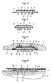
- Fig. 1 est une vue en coupe transversale d'une bande selon un premier mode de réalisation de l'invention ;
- Fig. 2 est une coupe longitudinale arrachée des extrémités de la bande de la Fig. 1 ;
- Fig. 3 est une vue analogue à la Fig. 1 et montre la bande assujettie à la face intérieure du moule, avant moulage ;
- Fig. 4 est une vue analogue à la Fig. 1 et montre l'article moulé fini qui porte la bande de retenue d'un revêtement ; et
- Fig. 5 à 8 sont des vues analogues respectivement aux Figs. 1 à 4 relativement à un second mode de réalisation.
- Fig. 1 is a cross-sectional view of a strip according to a first embodiment of the invention;
- Fig. 2 is a longitudinal section cut away from the ends of the strip of FIG. 1;
- Fig. 3 is a view similar to FIG. 1 and shows the strip secured to the inner face of the mold, before molding;
- Fig. 4 is a view similar to FIG. 1 and shows the finished molded article which carries the retaining strip of a coating; and
- Fig. 5 to 8 are views similar respectively to FIGS. 1 to 4 relative to a second embodiment.
On a montré aux Figs 3 et 7 une partie d'un moule 1, par exemple en aluminium, destiné à la fabrication d'un article moulé 2, montré en partie aux Figs 4 et 8. Cet article est, dans le mode d'application préféré de l'invention, une assise ou un dossier en mousse de polyuréthane , du type polyéther, pour siège de véhicule.We have shown in Figs 3 and 7 a part of a
L'article est destiné à recevoir un revêtement 3, (Figs 4 et 8), par exemple une housse de siège dans l'application considérée. L'article moulé 2 retient le revêtement 3 par l'intermédiaire d'une bande accrochante 4 qui est assujettie fixement à l'article moulé 2 et qui, sur sa face tournée vers le revêtement 3, porte des éléments d'accrochage 5, par exemple en forme de crochets, destinés à coopérer avec le verso du revêtement 3 qui présente, à cet effet, une structure 6 fibreuse ou pelucheuse, par exemple du type jersey gratté formant des boucles.The article is intended to receive a covering 3, (Figs 4 and 8), for example a seat cover in the application considered. The molded
De façon connue, la bande 4 est assujettie à l'article moulé 2, sur la face extérieure de celui-ci, lors de l'opération de moulage elle-même. Pour cela, comme montré à la Fig. 3, la bande 4 est provisoirement fixée sur la face intérieure 7 de la cavité de moulage 8 ménagée dans le moule 1. Pour une telle liaison, par exemple, la bande 4, sur sa face extérieure portant les éléments d'accrochage 5, présente deux zones marginales longitudinales démunies d'éléments d'accrochage et portant une enduction adhésive 9 (Fig 1-4) protégée par une pellicule 10 destinée à être enlevée lors du collage de la bande 4 sur la face intérieure 7 du moule. Comme décrit ultérieurement à propos du mode de réalisation des Figs 5 à 8, la bande 4 peut être retenue par voie magnétique à l'aide d'aimants prévus dans la paroi du moule.In known manner, the
Pour la réception de la bande 4, le moule 1 présente une cavité 11 (Figs 3 et 7) de réception des éléments d'accrochage 5 et, éventuellement, de part et d'autre de cette cavité, deux petites cavités latérales (12) pour la réception des zones marginales de la bande 4, ces zones, si elles sont encollées, étant dégagées par enlèvement des pellicules de protection 10. La profondeur de la cavité ou gorge principale 11 est telle que les éléments d'accrochage 5 peuvent venir porter contre son fond et que, si on prévoit les cavités latérales 12, la face de la semelle 13 opposée à celle qui porte les éléments d'accrochage affleure la face intérieure du moule 1 ; les cavités ou gorges latérales 12 ont une profondeur qui correspond sensiblement à l'épaisseur de la semelle 13. De la sorte, la face de la semelle 13 opposée à celle qui porte les éléments d'accrochage 5 prolonge la surface intérieure 7 sans solution de continuité ; de plus, la bande 4 est maintenue en appui contre le moule 1, d'une part, par les zones latérales en appui dans les cavités 12 et, d'autre part, le cas échéant, au centre par les éléments d'accrochage 5 en appui contre le fond de la cavité 11. Ainsi, lors du moussage du produit de moulage, la pression de ce produit qui s'exerce sur la bande 4 ne provoque aucune déformation de celle-ci.For the reception of the
Du fait que la face de la semelle 13 tournée vers l'intérieur du moule est au niveau de la face intérieure 7 de celui-ci, cette semelle est en saillie, d'une distance égale à son épaisseur, sur l'article fini 2, comme montré aux Figs 4 et 8.Because the face of the sole 13 facing the interior of the mold is at the
Pour assurer une adhérence parfaite de la bande 4 avec le produit de moulage, on prévoit, de façon connue, des éléments d'ancrage 14 qui font saillie de la semelle 13, vers l'intérieur du moule, sensiblement à angle droit par rapport à la semelle. Chaque élément d'ancrage comporte une tige ou pied 15 dont l'extrémité libre, éloignée de la semelle 13, porte une tête élargie 16. La tête 16 peut avoir toute forme appropriée.To ensure perfect adhesion of the
En variante, les éléments d'ancrage 14 pourraient être remplacés par toute structure appropriée, par exemple un jersey, grillage ou analogue facilitant l'ancrage du produit de moulage.Alternatively, the
Pour éviter que, pendant le moulage, le produit de moulage, quand il est encore à l'état liquide, pénètre entre les éléments d'accrochage 5 et s'y fixe en diminuant ainsi le pouvoir accrochant de ceux-ci, on prévoit, selon l'invention, une fine pellicule de protection continue 17 (Figs 1 à 3 et 5 à 8) qui recouvre les éléments d'accrochage et qui s'étend entre les zones marginales de la bande et sur toute la longueur de celle-ci.To avoid that, during molding, the molding product, when it is still in the liquid state, penetrates between the
La pellicule 17 peut être assujettie à la semelle 13, sur les zones marginales longitudinales, par tout moyen approprié, par exemple par collage à l'aide d'un adhésif d'apport ou par soudage, notamment aux ultrasons avec écrasement des éléments d'accrochage dans les zones de collage. On utilisera de préférence cette dernière technique qui permet d'écraser une ou deux rangées d'éléments d'accrochage pendant le soudage lui-même pour la fixation de la pellicule sur la semelle. Sur les petits côtés, on peut se dispenser de prévoir un adhésif pour coller la bande sur le moule, en raison de la faible largeur et de la raideur de la semelle. Mais on pourrait aussi, par exemple pour des bandes larges, araser la semelle pour enlever quelques rangées d'éléments d'accrochage 5 et fixer la bordure de la pellicule 17 comme sur les grands côtés.The
Dans la réalisation des Figs 1 à 4, la pellicule 17 s'arrête à distance des bords longitudinaux extrêmes de la semelle 13, de manière à dégager une bordure libre pour l'adhésif 9 et sa pellicule de protection 10.In the embodiment of FIGS. 1 to 4, the
Suivant la variante des Figs 5 à 8, dans laquelle la pellicule 17 s'étend jusqu'au contour extérieur de la semelle, la bande 4 n'est pas collée au moule 1 mais est retenue par voie magnétique, comme décrit ci-après.According to the variant of FIGS. 5 to 8, in which the
Suivant une caractéristique de l'invention, la pellicule 17 est en une matière qui se dégrade physiquement et chimiquement à une température supérieure à celle à laquelle le produit de moulage est stabilisé physiquement et chimiquement.According to a characteristic of the invention, the
Par exemple, dans le cas où l'article moulé 2 est en mousse de type polyéther, obtenue par un procédé dit à froid, dans lequel la mousse est stabilisée à partir d'environ 50° C, on peut utiliser une pellicule 17 en polyoléfine, notamment un polyéthylène souple ou rigide, qui se dégrade à partir de 1000 C, ou encore un acétate de cellulose qui se dégrade à partir de 60° C.For example, in the case where the molded
L'épaisseur de la pellicule 17 est très faible, de l'ordre de quelques centièmes de millimètre, par exemple 2/100 mm.The thickness of the
Avant son insertion dans le moule 1 (Figs 1 et 2) la bande 4 porte la pellicule 17 qui enferme et protège les éléments d'accrochage 5, à la manière d'une enveloppe ou d'un cocon.Before its insertion into the mold 1 (Figs 1 and 2) the
Quand la bande 4, avec sa pellicule 17, est placée dans le moule (Fig 3), elle y est retenue provisoirement par l'adhésif 9, ou tout moyen équivalent, les éléments d'accrochage 5 étant recouverts par la pellicule 17 et s'étendant dans la cavité 11, éventuellement munie d'évents 18.When the
Pendant le processus de moulage, le produit liquide de moulage est introduit dans la cavité de moulage 8 et, à mesure que la température augmente, sous l'effet d'un chauffage commandé, il se stabilise graduellement, à la fois dans sa forme et dans sa structure chimique. Tant qu'il est liquide ou plus ou moins visqueux, c'est-à-dire à température relativement basse, la pellicule 17 reste intacte, de même que sa liaison avec la semelle 13, et interdit toute pénétration du produit dans l'espace 19 fermé qu'elle définit avec la semelle 13 et qui renferme et protège les éléments d'accrochage 5. Ces derniers sont ainsi protégés tant que le produit de moulage est fluide. A mesure que la température continue à croître, par commande extérieure, la matière de la pellicule 17 commence alors à se dégrader. Etant donné la faible épaisseur de la pellicule 17, cette dégradation se manifeste par une rétraction, phénomène en lui-même connu, qui donne naissance à un volume de matière extrêmement faible. Cette matière de dégradation, même si elle se dépose totalement sur les éléments d'accrochage 5, est d'un volume très faible, incapable d'encrasser suffisamment ceux-ci pour en diminuer de façon appréciable ou significative le pouvoir accrochant.During the molding process, the liquid molding product is introduced into the
A la fin du processus de moulage, la pellicule 17 est au moins partiellement et en général totalement dégradée et détruite, les produits de dégradation s'étant déposés, pour leur partie solide, sur la semelle 13, sur les éléments d'accrochage 5 et sur la surface de la cavité 11, de sorte que, au démoulage, les éléments 5 sont complètement dégagés et peuvent ultérieurement recevoir le revêtement 3 sans aucune opération supplémentaire et conteuse de nettoyage.At the end of the molding process, the
Ainsi, grâce à l'invention qui prévoit la pellicule 17 constituant une enveloppe fermée et étanche, on protège en toute certitude les éléments d'accrochage 5 contre un encrassement par le produit de moulage ; suivant une caractéristique particulière, cette pellicule se détruit automatiquement par effet thermique après que le produit de moulage s'est stabilisé.Thus, thanks to the invention which provides the
Mais, suivant une autre conception, la matière de la pellicule de protection 17 pourrait ne pas être affectée pendant le moulage, la destruction de cette pellicule se faisant ultérieurement par voie chimique, mécanique ou thermique. Dans ce dernier cas, on pourrait par exemple soumettre l'article moulé fini 2, portant la bande 4 avec sa pellicule 17, à un chauffage superficiel bref et intense, notamment à la flamme, par exemple pour le traitement de l'article 2 en surface, simultanément à la destruction thermique de la pellicule 17.However, according to another concept, the material of the
Suivant la variante représentée aux Figs 5 à 8, on place dans l'espace 19, entre le sommet des éléments d'accrochage 5 et la pellicule 17, un feuillard 20 relativement rigide. Ce feuillard a la même largeur (Fig 5) et la même longueur (Fig 6) que la partie de la semelle 13 portant des éléments d'accrochage 5. Ce feuillard est par exemple en feuille métallique de quelques dizièmes de millimètre d'épaisseur. Avantageusement, il est en un matériau magnétique, par exemple en tôle à base de fer, pour pouvoir être attiré par des aimants 21 noyés dans le fond de la cavité 11 du moule 1. On assure ainsi le maintien en place de la bande 4 pendant le moulage (Fig 7).According to the variant shown in FIGS. 5 to 8, a relatively
Le feuillard 20, outre son rôle éventuel de moyen de maintien de la bande dans la cavité 11, donne à l'ensemble composite constitué par la bande 4 proprement dite et la pellicule 17 une raideur facilitant la mise en place de cet ensemble dans le moule 1. Par ailleurs, après l'opération de moulage, il facilite le détachement de la pellicule 17 d'avec la bande 4 ancrée dans l'article moulé 2.The
Le détachement de la pellicule 17 peut se faire soit par décollement des zones marginales, soit par arrachement, soit encore par découpe de la pellicule. On a recours au décollement si l'adhérence entre la pellicule 17 et les zones marginales de la semelle 13 n'est pas trop forte ; on a recours à l'arrachement s'il importe peu que subsiste éventuellement, sur chacune des zones marginales longitudinales de la semelle, une languette 17a (Fig 8) correspondant au reliquat non enlevé de la pellicule ; dans les deux cas ci-dessus, après que la pellicule 17 a été entaillée sur l'un des petits côtés de la bande 4, on saisit à la main les bords superposés du feuillard et de la pellicule et on tire l'ensemble en le soulevant progressivement, à la manière d'un pelage, ce qui provoque l'enlèvement de la pellicule, avec ou sans les parties marginales de la pellicule initialement collées à la semelle 13. Dans ces opérations, les bords du feuillard constituent des bords d'appui favorisant le décollement. Dans le cas d'une division de la pellicule, les bords longitudinaux du feuillard constituent en quelque sorte deux arêtes d'appui ou de coupe le long ou près desquelles s'effectue l'arrachement. Dans le troisième cas, on peut passer une lame coupante en s'appuyant sur les bords longitudinaux du feuillard, ou encore au voisinage immédiat des parties marginales collées de la pellicule pour obtenir une séparation nette ; après la découpe, il subsiste les languettes 17a à bords nets ; pour les petits côtés de la bande, on peut procéder de même.The detachment of the
Avant son insertion dans le moule 1 (Figs 1 et 2),la bande 4 porte la pellicule 17 qui enferme et protège les éléments d'accrochage 5, à la manière d'une enveloppe ou d'un cocon, dans l'espace fermé 19.Before its insertion into the mold 1 (Figs 1 and 2), the
Quand la bande 4, avec sa pellicule 17, est placée dans le moule (Fig 7), elle y est retenue provisoirement par l'adhésif ou les aimants 21, les éléments d'accrochage 5 étant recouverts par la pellicule 17 et s'étendant dans la cavité 11, éventuellement munie d'évents 18.When the
Pendant le processus de moulage, le produit liquide de moulage est introduit dans la cavité de moulage 8 et, à mesure que la température augmente, sous l'effet d'un chauffage commandé, il se stabilise graduellement, à la fois dans sa forme et dans sa structure chimique. Pendant le moulage, la pellicule 17 interdit toute pénétration du produit dans l'espace 19. Les éléments d'accrochage 5 sont ainsi protégés contre la pénétration du liquide de moulage.During the molding process, the liquid molding product is introduced into the
Bien entendu, la pellicule 17 est choisie en une matière résistant aux températures de moulage.Of course, the
A la fin de l'opération de moulage, l'article 2, portant la bande 4 et la pellicule 17, est sorti du moule 1, après quoi on enlève la pellicule comme indiqué ci-dessus.At the end of the molding operation, the
Claims (21)
Applications Claiming Priority (4)
| Application Number | Priority Date | Filing Date | Title |
|---|---|---|---|
| FR8319926 | 1983-12-13 | ||
| FR8319926A FR2556271B1 (en) | 1983-12-13 | 1983-12-13 | METHOD FOR FIXING A STRIP OR THE LIKE HAVING HANGING ELEMENTS ON AN ARTICLE MOLDING, AND STRIP FOR IMPLEMENTING SAME |
| FR8410033A FR2566316B2 (en) | 1984-06-26 | 1984-06-26 | METHOD FOR FIXING A STRIP OR THE LIKE HAVING HANGING ELEMENTS ON AN ARTICLE MOLDING, AND STRIP FOR IMPLEMENTING SAME |
| FR8410033 | 1984-06-26 |
Publications (3)
| Publication Number | Publication Date |
|---|---|
| EP0145603A2 true EP0145603A2 (en) | 1985-06-19 |
| EP0145603A3 EP0145603A3 (en) | 1986-01-22 |
| EP0145603B1 EP0145603B1 (en) | 1988-04-27 |
Family
ID=26223720
Family Applications (1)
| Application Number | Title | Priority Date | Filing Date |
|---|---|---|---|
| EP84402547A Expired EP0145603B1 (en) | 1983-12-13 | 1984-12-11 | Strip fastener to be fixed on a moulded article during the moulding process, and method of attaching it |
Country Status (4)
| Country | Link |
|---|---|
| US (2) | US4693921A (en) |
| EP (1) | EP0145603B1 (en) |
| CA (1) | CA1256278A (en) |
| DE (2) | DE3470683D1 (en) |
Cited By (17)
| Publication number | Priority date | Publication date | Assignee | Title |
|---|---|---|---|---|
| EP0168241A2 (en) * | 1984-07-10 | 1986-01-15 | Minnesota Mining And Manufacturing Company | Fastener assembly with improved temporary attachment layer |
| EP0168240A2 (en) * | 1984-07-10 | 1986-01-15 | Minnesota Mining And Manufacturing Company | Fastener assembly with heat shrinkable film cover |
| EP0205489A1 (en) * | 1984-11-20 | 1986-12-30 | Velcro Usa | Separable fasteners as well as method and apparatus for adapting separable fasteners for attachment to other objects. |
| EP0213478A2 (en) * | 1985-08-16 | 1987-03-11 | The Firestone Tire & Rubber Company | Apparatus for introducing appliques to the sidewall of a tire |
| US4776068A (en) * | 1986-10-20 | 1988-10-11 | Velcro Industries B. V. | Quiet touch fastener material |
| EP0286249A2 (en) * | 1987-04-07 | 1988-10-12 | TRW United-Carr Ltd. | Connectors |
| FR2617085A1 (en) * | 1987-03-06 | 1988-12-30 | United Carr Gmbh Trw | FIXING ELEMENT INTEGRATED INTO A FOAM, FOR A HARD FOAM COVERING OBTAINED BY A FOAM FORMATION PROCESS |
| US4814036A (en) * | 1985-07-17 | 1989-03-21 | Velcro Industries B.V. | Method for adapting separable fasteners for attachment to other objects |
| US4933224A (en) * | 1985-07-17 | 1990-06-12 | Velcro Industries, B.V. | Method for adapting separable fasteners for attachment to other objects |
| GB2214860B (en) * | 1987-04-30 | 1991-11-20 | Sumitomo Chemical Co | Method of manufacturing multi-layer molded products |
| EP0693364A1 (en) * | 1994-07-20 | 1996-01-24 | Hutchinson S.A. | Tyre manufacturing process and tyres obtained thereby |
| WO1999027811A1 (en) * | 1997-11-28 | 1999-06-10 | Firma Gottlieb Binder Gmbh & Co. | Adhesive body |
| US7425360B2 (en) | 2004-03-02 | 2008-09-16 | Velcro Industries B.V. | Touch fastener products |
| US7648751B2 (en) | 2006-10-17 | 2010-01-19 | Velero Industries B.V. | Touch fastener products |
| US9826801B2 (en) | 2015-06-17 | 2017-11-28 | Velcro BVBA | Mold-in touch fastening product |
| US9918526B2 (en) | 2015-06-17 | 2018-03-20 | Velcro BVBA | Mold-in touch fastening product |
| US10426231B2 (en) * | 2014-03-13 | 2019-10-01 | Ykk Corporation | Molded surface fastener, cushion body, cushion body manufacturing method, and molding die |
Families Citing this family (84)
| Publication number | Priority date | Publication date | Assignee | Title |
|---|---|---|---|---|
| CA1256278A (en) * | 1983-12-13 | 1989-06-27 | Bruno Queval | Gripping strip to be fixed to an article in the process of molding said article, and means for fixing said strip |
| US4881997A (en) * | 1985-07-17 | 1989-11-21 | Velcro Industries. B.V. | Method for adapting separable fasteners for attachment to other objects |
| KR940006314B1 (en) * | 1987-12-15 | 1994-07-16 | 가부시끼가이샤 구라레 | Fastener component |
| JPH028020A (en) * | 1988-06-28 | 1990-01-11 | Ikeda Bussan Co Ltd | Integral molding of skin material and padding material |
| US4923744A (en) * | 1989-01-09 | 1990-05-08 | Peeters Emma L | Presentation basket |
| US5040787A (en) * | 1989-02-06 | 1991-08-20 | Brotman Eric M | Auxiliary magnetic weights |
| US5256121A (en) * | 1989-02-06 | 1993-10-26 | Brotman Eric M | Auxiliary magnetic weights |
| US5061540A (en) * | 1990-01-25 | 1991-10-29 | Velcro Industries B.V. | Separable fasteners for attachment to other objects |
| US5005242A (en) * | 1990-02-06 | 1991-04-09 | Velcro Industries B.V. | Foamed seat cushion |
| US5067772A (en) * | 1990-03-29 | 1991-11-26 | Michigan Seat Company | Foam seat with insert |
| US5259905A (en) * | 1990-08-09 | 1993-11-09 | Velcro Industries B.V. | Method for manufacturing a separable fastener for incorporation into a seat bun |
| US5171395A (en) * | 1990-08-09 | 1992-12-15 | Velcro Industries B.V. | Shaped mold-in |
| DK0577697T3 (en) * | 1991-03-06 | 2000-01-03 | Aircast Inc | Injection molded orthopedic device and method |
| US5152037A (en) * | 1991-03-07 | 1992-10-06 | Schiek James M | Adjustable hook and loop-type fastener assembly |
| WO1992019119A1 (en) * | 1991-05-03 | 1992-11-12 | Velcro Industries B.V. | Insert mold-in |
| US5786061A (en) * | 1991-05-03 | 1998-07-28 | Velcro Industries B.V. | Separable fastener having a perimeter cover gasket |
| US5540970A (en) * | 1991-05-03 | 1996-07-30 | Velcro Industries B.V. | Die cut mold-in |
| JP2708084B2 (en) * | 1992-03-23 | 1998-02-04 | ワイケイケイ株式会社 | Method of attaching hook-and-loop fastener to seat cushion material and foam molding die |
| US5422156A (en) * | 1993-04-23 | 1995-06-06 | Aplix, Inc. | Fastening member with ferromagnetic attachment strip |
| JPH0742714A (en) * | 1993-08-05 | 1995-02-10 | Minnesota Mining & Mfg Co <3M> | Attaching member for protecting and decorating body and manufacture thereof |
| JPH07275014A (en) * | 1994-04-01 | 1995-10-24 | Minnesota Mining & Mfg Co <3M> | Face-toface engaging fastener member and its manufacture, and affixing member equipped with face-to-face engaging fastener |
| JP2704859B2 (en) * | 1995-06-09 | 1998-01-26 | 難波プレス工業株式会社 | Guide member and method for integral foam molding |
| US5500268A (en) * | 1995-01-31 | 1996-03-19 | Aplix, Inc. | Fastener assembly with magnetic side and end seals and method |
| US5665449A (en) * | 1995-01-31 | 1997-09-09 | Aplix, Inc. | Fastener assembly with mechanical end seals |
| US5606781A (en) * | 1995-02-17 | 1997-03-04 | Velcro Industries, B.V. | Separable fastener having a bald perimeter rib bounded by fastening elements |
| US6540863B2 (en) | 1995-02-17 | 2003-04-01 | Velcro Industries B.V. | Forming fastener components of multiple streams of resin |
| US5725928A (en) * | 1995-02-17 | 1998-03-10 | Velcro Industries B.V. | Touch fastener with magnetic attractant |
| US5945193A (en) * | 1995-12-06 | 1999-08-31 | Velcro Industries B.V. | Touch fastener with porous metal containing layer |
| US5766385A (en) * | 1995-12-06 | 1998-06-16 | Velcro Industries B.V. | Separable fastener having die-cut protective cover with pull tab and method of making same |
| US5766723A (en) * | 1996-11-12 | 1998-06-16 | Woodbridge Foam Corporation | Fastener assembly with peripheral seal |
| US5900303A (en) * | 1997-09-30 | 1999-05-04 | Aplix, Inc. | Fastener assembly with mechanical end seals |
| US6187247B1 (en) | 1998-05-13 | 2001-02-13 | Velcro Industries B.V. | Injection molding parts with fastener elements |
| US6224364B1 (en) | 1998-09-21 | 2001-05-01 | Velcro Industries B.V. | Injection molding products having fastener elements |
| US6596371B1 (en) * | 2000-01-19 | 2003-07-22 | Aplix, Inc. | Component for overcasting for a moulded object |
| US6656563B1 (en) * | 2000-05-23 | 2003-12-02 | Velcro Industries B.V. | Segmented separable fastener |
| US7022394B2 (en) * | 2001-05-04 | 2006-04-04 | Ykk Corporation | Fastener strip with discrete magnetically attractable area, and method and apparatus of making same |
| US6913810B2 (en) * | 2002-01-15 | 2005-07-05 | Velcro Industries B.V. | Interface tape |
| US7207946B2 (en) * | 2002-05-09 | 2007-04-24 | Spiration, Inc. | Automated provision of information related to air evacuation from a chest cavity |
| US7146690B2 (en) * | 2002-10-19 | 2006-12-12 | General Motors Corporation | Releasable fastener system |
| US7013536B2 (en) | 2002-10-19 | 2006-03-21 | General Motors Corporation | Releasable fastener systems and processes |
| US6983517B2 (en) * | 2002-10-19 | 2006-01-10 | General Motors Corporation | Releasable fastener system |
| US7032282B2 (en) | 2002-10-19 | 2006-04-25 | General Motors Corporation | Releasable fastener system |
| US7308738B2 (en) * | 2002-10-19 | 2007-12-18 | General Motors Corporation | Releasable fastener systems and processes |
| US6944920B2 (en) * | 2002-10-19 | 2005-09-20 | General Motors Corporation | Electrostatically releasable fastening system and method of use |
| JP4015983B2 (en) * | 2002-10-19 | 2007-11-28 | ゼネラル・モーターズ・コーポレーション | Magnetorheological nanocomposite elastomer for releasable accessories |
| US7013538B2 (en) | 2002-10-19 | 2006-03-21 | General Motors Corporation | Electroactive polymer releasable fastening system and method of use |
| US7140081B2 (en) * | 2002-10-19 | 2006-11-28 | General Motors Corporation | Releasable fastener system |
| US6973701B2 (en) * | 2002-10-19 | 2005-12-13 | General Motors Corporation | Releasable fastening system based on ionic polymer metal composites and method of use |
| US7153113B2 (en) * | 2003-07-24 | 2006-12-26 | Ykk Corporation Of America | Molds having a veneered pedestal for forming a foam object |
| US7219113B2 (en) * | 2003-09-26 | 2007-05-15 | International Business Machines Corporation | Pseudo-random binary sequence checker with automatic synchronization |
| CA2555671A1 (en) | 2004-02-10 | 2005-08-25 | Avery Dennison Corporation | Fastening member for a molded article |
| DE102004015321A1 (en) * | 2004-03-30 | 2005-10-20 | Binder Gottlieb Gmbh & Co Kg | Fastener part |
| US9220622B2 (en) | 2004-12-22 | 2015-12-29 | Ossur Hf | Orthopedic device |
| US8585623B2 (en) | 2004-12-22 | 2013-11-19 | Ossur Hf | Orthopedic device |
| US8231560B2 (en) | 2004-12-22 | 2012-07-31 | Ossur Hf | Orthotic device and method for securing the same |
| US20060183165A1 (en) * | 2005-02-15 | 2006-08-17 | Zhang Sean X | Combination of chemical differentiators and their applications in mass sensing-based chemical sensor systems |
| US20060261109A1 (en) * | 2005-05-18 | 2006-11-23 | Browne Alan L | Cargo container including an active material based releasable fastener system |
| CA2658441A1 (en) * | 2006-07-24 | 2008-01-31 | Armfoam Inc. | Play surface layer structure |
| EP2073659B1 (en) * | 2006-10-17 | 2013-06-19 | Velcro Industries B.V. | Fastener systems for seat cushions |
| US20090106953A1 (en) * | 2007-10-24 | 2009-04-30 | Wittig Wayne | Apparatus and method for fastening by capturing protruding members in corresponding flexible openings |
| US7954208B2 (en) * | 2007-10-31 | 2011-06-07 | Avery Dennison Corporation | Fastening member for a molded article |
| US20090276986A1 (en) * | 2008-05-12 | 2009-11-12 | Velcro Industries B.V. | Touch fastener products |
| TWI370726B (en) * | 2008-10-21 | 2012-08-21 | Taiwan Paiho Ltd | Fastening strap and manufacturing method thereof |
| TWI403282B (en) * | 2008-12-05 | 2013-08-01 | Taiwan Paiho Ltd | Fastening assembly and cushion having fastening assembly |
| TW201023783A (en) * | 2008-12-26 | 2010-07-01 | Taiwan Paiho Ltd | Fastening assembly and cushion having fastening assembly |
| TWI381813B (en) * | 2010-01-12 | 2013-01-11 | Taiwan Paiho Ltd | A Velcro assembly for a foamed article and a foamed article comprising the adhesive tape assembly |
| US20150015037A1 (en) * | 2012-10-15 | 2015-01-15 | Taiwan Paiho Limited | Hook-and-loop component embedded with foam material and cushion thereof |
| WO2014078264A2 (en) | 2012-11-13 | 2014-05-22 | Ossur Hf | Fastener member for affixation to a structure in an orthopedic device and method for securing the same |
| CN105228564B (en) | 2013-01-07 | 2017-11-14 | 奥索有限责任公司 | Orthopedic appliance and its fixing means |
| WO2014120393A1 (en) | 2013-01-31 | 2014-08-07 | Ossur Hf | Progressive force strap assembly for use with an orthopedic device |
| US9375341B2 (en) | 2013-01-31 | 2016-06-28 | Ossur Hf | Orthopedic device having detachable components for treatment stages and method for using the same |
| US9498025B2 (en) | 2013-04-08 | 2016-11-22 | Ossur Hf | Strap attachment system for orthopedic device |
| DE102013009091A1 (en) | 2013-05-28 | 2014-12-04 | Gottlieb Binder Gmbh & Co. Kg | Method for producing a connecting part, connecting part produced according to the method, tool for producing such a connecting part and fastening system with such a connecting part |
| US10052221B2 (en) | 2015-01-06 | 2018-08-21 | Ossur Iceland Ehf | Orthopedic device for treating osteoarthritis of the knee |
| US10021947B2 (en) * | 2016-02-26 | 2018-07-17 | Ykk Corporation | Fastening tape with improved attachment systems |
| US11253384B2 (en) | 2016-06-06 | 2022-02-22 | Ossur Iceland Ehf | Orthopedic device, strap system and method for securing the same |
| US11850175B2 (en) | 2016-06-06 | 2023-12-26 | Ossur Iceland Ehf | Orthopedic device, strap system and method for securing the same |
| US11547589B2 (en) | 2017-10-06 | 2023-01-10 | Ossur Iceland Ehf | Orthopedic device for unloading a knee |
| USD908458S1 (en) | 2018-10-08 | 2021-01-26 | Ossur Iceland Ehf | Hinge cover |
| USD882803S1 (en) | 2018-10-08 | 2020-04-28 | Ossur Iceland Ehf | Orthopedic shell |
| USD888258S1 (en) | 2018-10-08 | 2020-06-23 | Ossur Iceland Ehf | Connector assembly |
| US11241986B2 (en) * | 2019-06-05 | 2022-02-08 | Lear Corporation | Vehicle seating system and method |
| CN115461548A (en) * | 2020-04-29 | 2022-12-09 | 维克罗知识产权控股有限责任公司 | In-mold fastener |
| EP4267049A1 (en) | 2020-12-28 | 2023-11-01 | Ossur Iceland Ehf | Sleeve and method for use with orthopedic device |
Family Cites Families (22)
| Publication number | Priority date | Publication date | Assignee | Title |
|---|---|---|---|---|
| US3181913A (en) * | 1964-03-27 | 1965-05-04 | Guido Lewis | Display hassock |
| US3408705A (en) * | 1966-07-07 | 1968-11-05 | Minnesota Mining & Mfg | Fastener articles |
| FR1601166A (en) * | 1968-03-06 | 1970-08-10 | Clothing mattress carcass with foam | |
| US3870741A (en) * | 1970-04-20 | 1975-03-11 | Goodyear Tire & Rubber | Method of making a foam package |
| US3940524A (en) * | 1971-05-14 | 1976-02-24 | Bayer Aktiengesellschaft | Article comprising foam plastic covered with an outer surface strengthening layer |
| FR2405123A1 (en) * | 1977-10-06 | 1979-05-04 | Aplix Sa | Foam seats and backrests for automobiles - have self-attaching tapes for covers bonded to product during moulding |
| FR2423666A1 (en) * | 1978-02-13 | 1979-11-16 | Aplix Sa | Mfg. foam mouldings with surface patches of hooked pile tape - for integral anchorages to secure fabric covers |
| FR2463870A1 (en) * | 1979-08-20 | 1981-02-27 | Faure Bertrand | Composite tapes for hooked pile anchorages for upholstery covers etc. - having a coarse fabric backing for enhanced adhesive grip |
| FR2466330A1 (en) * | 1979-10-05 | 1981-04-10 | Roth Sa Freres | Seat cushions moulded with integral surface tapes of piled fabric - for anchoring close-fitted covers bearing hooked pile tabs |
| US4499130A (en) * | 1982-03-01 | 1985-02-12 | Carprotec, Inc. | Temporary strippable protective laminate |
| US4470857A (en) * | 1982-06-25 | 1984-09-11 | R. A. Casalou, Inc. | Method of making foam plastic article |
| JPS5989132A (en) * | 1982-11-13 | 1984-05-23 | Hiroshima Kasei Kk | Manufacture of carpet mat and mold therefor |
| FR2553156B1 (en) * | 1983-10-07 | 1985-12-27 | Aplix Sa | STRIP OR THE LIKE HAVING HANGING ELEMENTS AND INTENDED TO BE CARRIED BY A MOLDED ARTICLE, AND MOLD USED |
| CA1256278A (en) * | 1983-12-13 | 1989-06-27 | Bruno Queval | Gripping strip to be fixed to an article in the process of molding said article, and means for fixing said strip |
| US4802939A (en) * | 1983-12-13 | 1989-02-07 | Aplix, S.A. | Method for attaching a fastening tape to a molded article |
| US4563380A (en) * | 1984-07-10 | 1986-01-07 | Minnesota Mining And Manufacturing Company | Fastener assembly with improved temporary attachment layer |
| US4710414A (en) * | 1984-07-10 | 1987-12-01 | Minnesota Mining And Manufacturing Company | Fastener assembly with heat shrinkable film cover |
| IE57148B1 (en) * | 1984-11-20 | 1992-05-06 | Velcro Ind | Separable fasteners as well as method and apparatus for adapting separable fasteners for attachment to other objects |
| US4673542A (en) * | 1985-06-14 | 1987-06-16 | General Motors Corporation | Method of making a foamed seat or cushion having integral fasteners |
| US4814036A (en) * | 1985-07-17 | 1989-03-21 | Velcro Industries B.V. | Method for adapting separable fasteners for attachment to other objects |
| US4784890A (en) * | 1986-06-20 | 1988-11-15 | Minnesota Mining And Manufacturing Company | Fastener assembly with peripheral temporary attachment layer |
| US4842916A (en) * | 1987-01-19 | 1989-06-27 | Kuraray Company Ltd. | Separable fastener component & moldings attached with such fastener component |
-
1984
- 1984-10-12 CA CA000465312A patent/CA1256278A/en not_active Expired
- 1984-11-30 US US06/676,951 patent/US4693921A/en not_active Expired - Lifetime
- 1984-12-11 DE DE8484402547T patent/DE3470683D1/en not_active Expired
- 1984-12-11 DE DE198484402547T patent/DE145603T1/en active Pending
- 1984-12-11 EP EP84402547A patent/EP0145603B1/en not_active Expired
-
1989
- 1989-01-11 US US07/295,778 patent/US4933035A/en not_active Expired - Lifetime
Non-Patent Citations (1)
| Title |
|---|
| None |
Cited By (25)
| Publication number | Priority date | Publication date | Assignee | Title |
|---|---|---|---|---|
| EP0168241A2 (en) * | 1984-07-10 | 1986-01-15 | Minnesota Mining And Manufacturing Company | Fastener assembly with improved temporary attachment layer |
| EP0168240A2 (en) * | 1984-07-10 | 1986-01-15 | Minnesota Mining And Manufacturing Company | Fastener assembly with heat shrinkable film cover |
| EP0168240A3 (en) * | 1984-07-10 | 1988-03-09 | Minnesota Mining And Manufacturing Company | Fastener assembly with heat shrinkable film cover |
| EP0168241A3 (en) * | 1984-07-10 | 1988-03-09 | Minnesota Mining And Manufacturing Company | Fastener assembly with improved temporary attachment layer |
| EP0205489A1 (en) * | 1984-11-20 | 1986-12-30 | Velcro Usa | Separable fasteners as well as method and apparatus for adapting separable fasteners for attachment to other objects. |
| EP0205489A4 (en) * | 1984-11-20 | 1987-04-15 | Velcro Usa | Separable fasteners as well as method and apparatus for adapting separable fasteners for attachment to other objects. |
| US4933224A (en) * | 1985-07-17 | 1990-06-12 | Velcro Industries, B.V. | Method for adapting separable fasteners for attachment to other objects |
| US4814036A (en) * | 1985-07-17 | 1989-03-21 | Velcro Industries B.V. | Method for adapting separable fasteners for attachment to other objects |
| EP0213478A2 (en) * | 1985-08-16 | 1987-03-11 | The Firestone Tire & Rubber Company | Apparatus for introducing appliques to the sidewall of a tire |
| EP0213478A3 (en) * | 1985-08-16 | 1988-06-01 | The Firestone Tire & Rubber Company | Apparatus for introducing appliques to the sidewall of a tire |
| US4776068A (en) * | 1986-10-20 | 1988-10-11 | Velcro Industries B. V. | Quiet touch fastener material |
| FR2617085A1 (en) * | 1987-03-06 | 1988-12-30 | United Carr Gmbh Trw | FIXING ELEMENT INTEGRATED INTO A FOAM, FOR A HARD FOAM COVERING OBTAINED BY A FOAM FORMATION PROCESS |
| EP0286249A3 (en) * | 1987-04-07 | 1990-05-02 | Trw United-Carr Ltd. | Connectors |
| EP0286249A2 (en) * | 1987-04-07 | 1988-10-12 | TRW United-Carr Ltd. | Connectors |
| GB2214860B (en) * | 1987-04-30 | 1991-11-20 | Sumitomo Chemical Co | Method of manufacturing multi-layer molded products |
| EP0693364A1 (en) * | 1994-07-20 | 1996-01-24 | Hutchinson S.A. | Tyre manufacturing process and tyres obtained thereby |
| FR2722730A1 (en) * | 1994-07-20 | 1996-01-26 | Hutchinson | PROCESS FOR THE MANUFACTURE OF TIRES AND TIRES OBTAINED BY SAID PROCESS |
| WO1999027811A1 (en) * | 1997-11-28 | 1999-06-10 | Firma Gottlieb Binder Gmbh & Co. | Adhesive body |
| US6299954B1 (en) | 1997-11-28 | 2001-10-09 | Firma Gottlieb Binder Gmbh & Co. | Adhesive body |
| US7425360B2 (en) | 2004-03-02 | 2008-09-16 | Velcro Industries B.V. | Touch fastener products |
| US7678318B2 (en) | 2004-03-02 | 2010-03-16 | Velcro Industries B.V. | Touch fastener products |
| US7648751B2 (en) | 2006-10-17 | 2010-01-19 | Velero Industries B.V. | Touch fastener products |
| US10426231B2 (en) * | 2014-03-13 | 2019-10-01 | Ykk Corporation | Molded surface fastener, cushion body, cushion body manufacturing method, and molding die |
| US9826801B2 (en) | 2015-06-17 | 2017-11-28 | Velcro BVBA | Mold-in touch fastening product |
| US9918526B2 (en) | 2015-06-17 | 2018-03-20 | Velcro BVBA | Mold-in touch fastening product |
Also Published As
| Publication number | Publication date |
|---|---|
| US4933035A (en) | 1990-06-12 |
| EP0145603B1 (en) | 1988-04-27 |
| EP0145603A3 (en) | 1986-01-22 |
| DE3470683D1 (en) | 1988-06-01 |
| DE145603T1 (en) | 1986-12-18 |
| US4693921A (en) | 1987-09-15 |
| CA1256278A (en) | 1989-06-27 |
Similar Documents
| Publication | Publication Date | Title |
|---|---|---|
| EP0145603B1 (en) | Strip fastener to be fixed on a moulded article during the moulding process, and method of attaching it | |
| EP0145523B1 (en) | Strap with hooking means connected to a moulded article, and mould used | |
| CA1312022C (en) | Presentation platter used for wrapping | |
| EP0291395B1 (en) | Device for protecting the part of the hair previously treated when applying a permanent wave, and process for making such a protective device | |
| EP2155462B1 (en) | Method and device for overmoulding a glass element using a seam portion including an insert and glass panel | |
| EP0795390A1 (en) | Container comprising a decorative label and method for producing this container | |
| FR2493112A1 (en) | METHOD FOR MANUFACTURING A SKI BOOT AND SKI BOOT, ACCORDING TO THIS METHOD | |
| CA1307378C (en) | Heat-shrinkable sleeve with uniform heating control means and fabrication process of that sleeve | |
| FR2527455A1 (en) | ANCHORING DEVICE OR LOCKING PEN FOR REAR-TYPE SAFETY BELTS | |
| FR2463870A1 (en) | Composite tapes for hooked pile anchorages for upholstery covers etc. - having a coarse fabric backing for enhanced adhesive grip | |
| FR2588353A1 (en) | CONNECTION IN PARTICULAR FOR TUBES AND PIPES | |
| EP0847848B1 (en) | Article comprising a moulded body and an inlaid decorative element and process for its manufacture | |
| FR2556271A1 (en) | Method for attaching a strip or the like, fitted with catching elements, to an article being moulded, and strip for its implementation | |
| EP1008317B1 (en) | Seat cushion, in particular for motor vehicle, and process for its manufacture | |
| FR2498981A1 (en) | LINE FOR THE PRODUCTION OF FILMS BY EXTRUSION | |
| FR2566316A2 (en) | Method for the attachment of a sheet or the like equipped with elements for fastening to an article during moulding, and sheet for its implementation | |
| FR2514990A1 (en) | Pet basket with removable cover - has complementary strips of hooked pile fastening fabric along bottom edges of side walls of frame and cover to hold cover in place | |
| EP1382427A1 (en) | Process for manufacturing a vehicle mud guard and mud guard made thereby | |
| FR2585986A2 (en) | Composite strip for lids of thermoplastic containers - has different strength glues about cut zone which form opening in lid | |
| FR2757804A1 (en) | GLAZING EQUIPPED WITH A PLASTIC FRAME, WORKPIECES AND METHOD FOR MANUFACTURING THE SAME | |
| EP3789183B1 (en) | Method and device for manufacturing a laminated trim part and part obtained | |
| FR2763535A1 (en) | Rotary moulding equipment producing a skin for e.g. foaming as automobile part | |
| FR2686996A1 (en) | Process for manufacturing a memory card comprising a micromodule equipped with a cover, and memory card thus obtained | |
| FR2869257A1 (en) | Automated process for making a projecting tongue to facilitate removal of protective strip on adhesive surface of extrusion uses end of strip on detachable portion of extrusion | |
| EP0449750A1 (en) | Method for making a shoe or sandal with an injection moulded sole and apparatus for carrying out this method |
Legal Events
| Date | Code | Title | Description |
|---|---|---|---|
| PUAI | Public reference made under article 153(3) epc to a published international application that has entered the european phase |
Free format text: ORIGINAL CODE: 0009012 |
|
| AK | Designated contracting states |
Designated state(s): DE GB IT |
|
| PUAL | Search report despatched |
Free format text: ORIGINAL CODE: 0009013 |
|
| RHK1 | Main classification (correction) |
Ipc: B29C 39/10 |
|
| AK | Designated contracting states |
Designated state(s): DE GB IT |
|
| ITCL | It: translation for ep claims filed |
Representative=s name: CALVANI SALVI VERONELLI |
|
| 17P | Request for examination filed |
Effective date: 19860716 |
|
| DET | De: translation of patent claims | ||
| 17Q | First examination report despatched |
Effective date: 19870409 |
|
| GRAA | (expected) grant |
Free format text: ORIGINAL CODE: 0009210 |
|
| AK | Designated contracting states |
Kind code of ref document: B1 Designated state(s): DE GB IT |
|
| REF | Corresponds to: |
Ref document number: 3470683 Country of ref document: DE Date of ref document: 19880601 |
|
| GBT | Gb: translation of ep patent filed (gb section 77(6)(a)/1977) | ||
| ITF | It: translation for a ep patent filed |
Owner name: CALVANI SALVI E VERONELLI S.R.L. |
|
| PLBI | Opposition filed |
Free format text: ORIGINAL CODE: 0009260 |
|
| 26 | Opposition filed |
Opponent name: VELCRO GROUP CORPORATION Effective date: 19890126 |
|
| ITTA | It: last paid annual fee | ||
| PLBM | Termination of opposition procedure: date of legal effect published |
Free format text: ORIGINAL CODE: 0009276 |
|
| STAA | Information on the status of an ep patent application or granted ep patent |
Free format text: STATUS: OPPOSITION PROCEDURE CLOSED |
|
| 27C | Opposition proceedings terminated |
Effective date: 19920214 |
|
| PGFP | Annual fee paid to national office [announced via postgrant information from national office to epo] |
Ref country code: GB Payment date: 19971205 Year of fee payment: 14 |
|
| PGFP | Annual fee paid to national office [announced via postgrant information from national office to epo] |
Ref country code: DE Payment date: 19980220 Year of fee payment: 14 |
|
| PG25 | Lapsed in a contracting state [announced via postgrant information from national office to epo] |
Ref country code: GB Free format text: LAPSE BECAUSE OF NON-PAYMENT OF DUE FEES Effective date: 19981211 |
|
| GBPC | Gb: european patent ceased through non-payment of renewal fee |
Effective date: 19981211 |
|
| PG25 | Lapsed in a contracting state [announced via postgrant information from national office to epo] |
Ref country code: DE Free format text: LAPSE BECAUSE OF NON-PAYMENT OF DUE FEES Effective date: 19991001 |