EP0146244A2 - Optical instrument for measuring displacement - Google Patents
Optical instrument for measuring displacement Download PDFInfo
- Publication number
- EP0146244A2 EP0146244A2 EP84307484A EP84307484A EP0146244A2 EP 0146244 A2 EP0146244 A2 EP 0146244A2 EP 84307484 A EP84307484 A EP 84307484A EP 84307484 A EP84307484 A EP 84307484A EP 0146244 A2 EP0146244 A2 EP 0146244A2
- Authority
- EP
- European Patent Office
- Prior art keywords
- diffraction grating
- beams
- variations
- optical path
- light
- Prior art date
- Legal status (The legal status is an assumption and is not a legal conclusion. Google has not performed a legal analysis and makes no representation as to the accuracy of the status listed.)
- Granted
Links
- 230000003287 optical effect Effects 0.000 title claims abstract description 98
- 238000006073 displacement reaction Methods 0.000 title claims abstract description 53
- 239000004065 semiconductor Substances 0.000 claims abstract description 21
- 238000001514 detection method Methods 0.000 claims description 14
- 238000005259 measurement Methods 0.000 claims description 7
- 238000010276 construction Methods 0.000 description 9
- 230000001427 coherent effect Effects 0.000 description 5
- 230000000694 effects Effects 0.000 description 5
- 238000010586 diagram Methods 0.000 description 4
- 239000011248 coating agent Substances 0.000 description 3
- 238000000576 coating method Methods 0.000 description 3
- 230000010355 oscillation Effects 0.000 description 3
- 230000001668 ameliorated effect Effects 0.000 description 2
- 238000004519 manufacturing process Methods 0.000 description 2
- 239000000463 material Substances 0.000 description 2
- 238000012544 monitoring process Methods 0.000 description 2
- 238000005070 sampling Methods 0.000 description 2
- 238000010420 art technique Methods 0.000 description 1
- 230000005540 biological transmission Effects 0.000 description 1
- 230000002950 deficient Effects 0.000 description 1
- 230000006866 deterioration Effects 0.000 description 1
- 230000002452 interceptive effect Effects 0.000 description 1
- 230000010363 phase shift Effects 0.000 description 1
- 230000001902 propagating effect Effects 0.000 description 1
- 239000000758 substrate Substances 0.000 description 1
- 230000004304 visual acuity Effects 0.000 description 1
Images


Classifications
-
- G—PHYSICS
- G01—MEASURING; TESTING
- G01D—MEASURING NOT SPECIALLY ADAPTED FOR A SPECIFIC VARIABLE; ARRANGEMENTS FOR MEASURING TWO OR MORE VARIABLES NOT COVERED IN A SINGLE OTHER SUBCLASS; TARIFF METERING APPARATUS; MEASURING OR TESTING NOT OTHERWISE PROVIDED FOR
- G01D5/00—Mechanical means for transferring the output of a sensing member; Means for converting the output of a sensing member to another variable where the form or nature of the sensing member does not constrain the means for converting; Transducers not specially adapted for a specific variable
- G01D5/26—Mechanical means for transferring the output of a sensing member; Means for converting the output of a sensing member to another variable where the form or nature of the sensing member does not constrain the means for converting; Transducers not specially adapted for a specific variable characterised by optical transfer means, i.e. using infrared, visible, or ultraviolet light
- G01D5/32—Mechanical means for transferring the output of a sensing member; Means for converting the output of a sensing member to another variable where the form or nature of the sensing member does not constrain the means for converting; Transducers not specially adapted for a specific variable characterised by optical transfer means, i.e. using infrared, visible, or ultraviolet light with attenuation or whole or partial obturation of beams of light
- G01D5/34—Mechanical means for transferring the output of a sensing member; Means for converting the output of a sensing member to another variable where the form or nature of the sensing member does not constrain the means for converting; Transducers not specially adapted for a specific variable characterised by optical transfer means, i.e. using infrared, visible, or ultraviolet light with attenuation or whole or partial obturation of beams of light the beams of light being detected by photocells
- G01D5/36—Forming the light into pulses
- G01D5/38—Forming the light into pulses by diffraction gratings
Definitions
- This invention relates to an optical instrument for detecting displacement of a scale, utilizing interference of light, in particular to such an instrument utilizing a multimode semiconductor laser device as a light source.
- precision of adjustment of the optical path lengths of the two beams mentioned above should be, for example, from several 10's of ⁇ m to several 100's of ⁇ m in the case where a semiconductor laser device is used without temperature compensation, although it is not possible to speak generally, because it depends on variations in wavelength which are to be allowed and the required precision as well as on the displacement length of the diffraction grating, to which a period of the interference signals corresponds.
- This invention has been made in order to take measures against the problems mentioned above and the object of this invention is to provide an optical instrument for measuring displacement, which permits to remove the drawbacks of the prior art techniques by detecting a difference between the optical path lengths of the two beams and by adjusting the optical path lengths without any special high precision elements or works and to make selectively necessary light beams interfere with each other.
- a suitably coherent multimode semiconductor laser is used as a light source and interference between two light beams diffracted by a diffraction grating is measured.
- an optical instrument for measuring displacement characterised in that it comprises a movable diffraction grating used as a scale, a light source, photodetectors, and means for making two light beams diffracted by said diffraction grating interfere with each other, in which displacement of said diffraction grating is detected, based on variations of interference signals, and wherein said light source is a multimode semiconductor laser device having a suitable coherency for making two necessary light beams with equal optical path lengths selectively interfere with each other.
- the invention also provides an optical instrument for measuring displacement, characterised in that it comprises a light source consisting of a multimode semiconductor laser device, a beam splitter for dividing the beam emerging from said light source into two, a diffracting grating on which these two split beams are projected, first reflectors which make two diffraction light beams of first order by the diffraction grating enter again said diffraction grating, said two diffracted light beams of first order diffracted again by said diffraction grating being made interfere with each other, a detector which detects interference light, variations in position of said diffraction grating being detected by measuring interference intensity of said interference light by means of said detector.
- a light source consisting of a multimode semiconductor laser device
- a beam splitter for dividing the beam emerging from said light source into two
- a diffracting grating on which these two split beams are projected
- first reflectors which make two diffraction light beams of first order by the diffraction grat
- Fig. 1 is a scheme showing the construction of an optical instrument for measuring displacement according to an embodiment of this invention, in which reference numeral 1 denotes a light source consisting of a multimode semiconductor laser device: 2 is a beam splitter for splitting a light beam into two; 3 is a diffraction grating used as a scale; 4, 7 and 13 are ⁇ /4 plates; 5 and 6 are a pair of mirrors; 8 is a half mirror; 9 and 12 are polarizing plates; and 10 and 11 are photodetectors.
- reference numeral 1 denotes a light source consisting of a multimode semiconductor laser device: 2 is a beam splitter for splitting a light beam into two; 3 is a diffraction grating used as a scale; 4, 7 and 13 are ⁇ /4 plates; 5 and 6 are a pair of mirrors; 8 is a half mirror; 9 and 12 are polarizing plates; and 10 and 11 are photodetectors.
- a light beam emerging from the multimode semiconductor laser device 1 enters the beam splitter 2 and is split at A into two beams, which proceed further toward B and C on the diffraction grating 3.
- Each of the light beams entering the diffraction grating 3 is diffracted and projected through a X/4 plate 4 or 7 onto a mirror 5 or 6.
- Each beam is reflected at D or E and enters again the diffraction grating 3.
- the beams diffracted again by the diffraction grating 3 return to the beam splitter 2 and interfere therein with each other. Thereafter they are projected through the half mirror 8 on the photodetectors 10 and 11, which detect interference intensity. In this manner displacement of the diffraction grating 3 used as a scale is measured.
- visibility of interference fringes in an interferometer is determined by coherency of the light source and by the difference between optical path lengths of the two interfering beams.
- a well coherent light source such as a laser device, in which single mode oscillation takes place, visibility is not lost, even if the difference between the two optical path lengths is great.
- visibility of interference fringes changes, when the difference between the two optical path lengths varies.
- This invention has been made by applying this principle to the optical instrument for measuring displacement.
- a commercialized semiconductor laser has characteristics of wavelength to temperature variation which is about 0.3nm/°C. Assuming that the range of temperature variations is ⁇ 10°C and that the wavelength is 780nm, the pitch of the diffraction grating in this optical system is approximately 0.55pm.
- tolerance of At is about 70 ⁇ m.
- Fig. 2 is a graph showing a relation between the difference ⁇ l between the two optical path lengths and the amplitude modulation of interference signals, obtained experimentally by means of a device arranged as indicated in Fig. 1.
- a multimode semiconductor laser devcie having fewer oscillation modes than that described above can be used for an optical system having a lower precision. In this case, characteristic curves varying more slowly than that shown in Fig. 2 are obtained.
- a multimode laser device is used only during adjustment of the optical system and after completion of the adjustment, it can be replaced by the original single mode laser device.
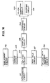
- Fig. 16 is a block diagram showing an example of the circuit displaying the difference of the optical path lengths in the embodiment shown in Fig. 1 and generating alarm and stop signals.
- Detection signals obtained by using a photodetector circuit 101 comprising the photodetectors 10 and 11 are sent through an amplifier circuit 102 to a counter circuit 109, whose output signals drive a displacement display circuit 110, where magnitude of the displacement is displayed.
- the detection signals are sent from the amplifier circuit 102 through a peak hold circuit 107 to an optical path difference display circuit 108, which displays the difference between the optical path lengths of the two beams.
- the detection signals are sent also from the amplifier circuit 102 to a sampling circuit 103, whose s.ampl- ing output signals are sent through a comparing circuit 104 to an alarm generation circuit 105, which produces alarm signals.
- the sampling output signals control also a stopping circuit 106, which stops the devices belonging to the measuring system.
- Fig. 3 is a scheme showing an example of the concrete construction of a signal detector, which can be used in a device according to this invention.
- Reference numerals 28 and 29 denote polarizing beam splitters and 30 to 33 represent photodetectors.
- Fig. 4 shows a concrete construction of the polarizing beam splitters 28 and 29 and photodetectors.
- An interference light beam 21 produced by the two beams is splitted into two, 21A and 21B, by a half mirror 22 and thereafter each of the splitted beams 21A and 21B is further split by means of a polarizing beam splitter 28 or 29 into two beams, which are directed toward two directions different by 90° from each other and projected to photodetectors 30, 31 or 32, 33. That is, after interference, components parallel to the sheet of the figure emerge toward the photodetector 30 and components perpendicular to the sheet emerge toward the photodetector 31.
- the phases of the two interference signals differ in phase by 180° from each other and their intensities are almost equal.
- Fig. 5 is a circuit diagram of a cancelling circuit used in the device according to this invention, in which D 3 and D 4 represent photodiodes and AMP denotes an amplifier. Two such cancelling circuits are disposed, corresponding to the polarizing beam splitters 28 and 29.
- the polarizing beam splitter 28 will be explained as . an example.
- the lst photodiode D3 is located at the position for the photodetector 30 and the 2nd photodiode D 4 is located at the position for the photodetector 31. Furthermore, these lst and 2nd photodiodes D 3 and D 4 are connected in series, and at the same time their connecting point is connected with the input terminal of the amplifier AMP. To the 1st and 2nd diodes D 3 , D 4 are connected reverse bias sources.
- Fig. 8 shows another example of the construction of the optical instrument for measuring displacement according to this invention, in which reference numeral 41 represents a diffraction grating used as a scale; 42 and 43 are a pair of mirrors; 52 and 53 are another pair of mirrors; 44 is a light source; 45 is a photodetector; 54 is a beam splitter for splitting the light beam emerging from the light source into two; and 55 denotes a normal to the diffraction grating 41.
- reference numeral 41 represents a diffraction grating used as a scale
- 42 and 43 are a pair of mirrors
- 52 and 53 are another pair of mirrors
- 44 is a light source
- 45 is a photodetector
- 54 is a beam splitter for splitting the light beam emerging from the light source into two
- 55 denotes a normal to the diffraction grating 41.
- the light beam 46 emerging from the light source 44 and projected on the beam splitter 54 is split into two, that is, the light beam 46A directed to the mirror 42 and the light beam 46B directed to the mirror 43.
- the light beams 46A and 46B are projected through the mirrors 42 and 43, respectively, on the diffraction grating 41 on both sides of the normal axis 55 with equal incident angles.
- the diffraction grating 41 is so disposed that grating vector is directed horizontally on the sheet of the figure, and that the direction of the displacement to be measured of the diffraction grating 41 used as a scale coincides with the direction of the grating vector.
- the light beam 46A reflected by the mirror 42 is further so diffracted that it is projected on the mirror 52, and at the same time the light beam 46B reflected by the mirror 43 is further so diffracted that it is projected on the mirror 53.
- the incident light beams 46A and 46B are so diffracted that the optical axis of one of the diffracted light beams 47A or 47B coincides with the optical axis of the others incident light beam.
- the diffracted light beams 47A, 47B are reflected by the mirrors 52, 53 and projected again on the diffraction grating 41. Here they are again diffracted.
- the diffracted light beam 47A coming from the mirror 52 is projected on the mirror 42 and the diffracted light beam 47B coming from the mirror 53 is projected on the mirror 43. They are reflected there and return to the beam splitter 54.
- the optical axis of the transmitted light beam of that reflected by the mirror 42 coincides with that of the reflected light beam of that reflected by the mirror 43 and they interfere with each other. Therefore, the displacement of the diffraction grating 41 used as a scale is measured by detecting this interference intensity by means of the photodetector 45.
- the detection signals and the displacement are related as follows.
- the complex amplitudes (excepting the term varying in time) E1, E 2 of the two incident beams passing through the origin after having been reflected by the mirrors 42, 43 can be expressed as follows.
- 6 denotes the incident angle
- k represents the wave- number of light of the used light source
- ⁇ 1 and ⁇ 2 are variations in phase on the optical paths during the interval from the point 0 when the original beam is split by the beam splitter into two to the moment when the split beams are projected on the diffraction grating.
- the transmission coefficient T can be expressed by the following equation.
- K is the grating vector of the diffraction grating, 2 ⁇ / ⁇ (A is the wavelength of the diffraction grating), and represents the phase of the grating.
- Equation (3) can be transformed as follows.
- the diffracted light beam is expressed by the product of E 1 , E 2 and T and thus E 11 and E 21 representing the respective diffracted light of 1st order are expressed as follows.
- E 13 and E 23 being complex amplitudes of the diffracted light beams of 1st order of the beams projected again on the diffraction grating 41 and diffracted by it, respectively, they can be calculated in the same manner as the equations mentioned above (5) and (6), as follows.
- interference intensity can be represented as follows.
- C ( ⁇ 2 + ⁇ 4 + ⁇ 6 - ⁇ 1 - ⁇ 3 - ⁇ 5 ) is a constant which does not vary, even if the diffraction grating used as a scale moves.
- C 0 and in this case the interference intensity I can be expressed as follows.
- phase variations which are 4 times as great as corresponding phase variations of the scale, appear in the interference signals.
- phase of the diffraction grating ⁇ can be calculated by the following equation.
- the instrument according to this invention As it is evident from the facts mentioned above, even if the wavelength of the light source varies, the optical path lengths of the two beams vary equally. Consequently, the instrument according to this invention is so constructed that the difference between the optical path lengths C is maintained always equal to 0. This situation is kept also, when the scale (diffraction grating) moves vertically.
- Fig. 9 shows a example showing the optical paths, in which the broken lines indicate optical paths in the case where the wavelength of the light source 44 varies. As indicated in the figure, since the optical paths of the two beams vary symmetrically, no variations in difference between the optical path lengths appear, and therefore the interference is not destroyed, because angular shifts at the end of the optical paths are also equal.
- Fig. 10 is a scheme where the diffraction grating 41 is moved vertically. In this case, even if the diffraction grating is displaced from 41(A) to 41(B) and the optical paths vary as indicated by the broken lines, the position of the diffraction varies symmetrically in the same manner as for the variations in wavelength described above, influences of the vertical displacement of the diffraction grating are cancelled by each other.
- Fig. 11 is a scheme showing the construction of another optical instrument for measuring displacement according to this invention, which is so constructed that the diffracted beams are reflected by a pair of mirrors 63, 64 and a beam splitter 54 makes them interfere with each other.
- Figs. 12 and 13 are schemes when variations in wavelength of the light source 44 are produced and when the diffraction grating 41 is displaced vertically, respectively, in the device shown in Fig. 9. Since influences of these variations are cancelled by each other by the same reason as that for Figs. 10 and 11, also in these cases they do not give rise to no problems.
- the incident angle 6 and the diffraction angle 6' of the two beams are equal.
- the diffraction of the two beams can satisfy, besides the grating equation consisting of another equation
- Fig. 14 is a schematical view showing the interior of a hologram atrecording, when a volume type hologram is used, in which reference numeral 65 denotes a coherent plane wave; 66 represents recording medium; and 67 is an enlarged view showing the interior of the hologram.
- the grating surface is perpendicular to the surface of the hologram. It is possible to obtain a high diffraction efficiency, which is as high as nearly 100%, by suitably selecting a material for the diffraction grating and by using a diffraction grating several ⁇ m thick. Moreover, fabrication of the scale becomes easier, because variations in grating pitch due to deformation of the material, which is often produced during the fabrication of a hologram. are small by the reason that the grating surface is perpendicular.
- Fig. 15 is a perspective view showing a concrete construction of the arrangement shown in Fig. 9, in which reference numeral 71 indicates a semiconductor laser device; 72 and 73 represent condenser lenses; 44 is a polarizing beam splitter; 75 is a grating for dividing incident wave; 76, 77 and 78 are X/4 plates; 79 and 80 are polarizing plates; 81, 82 and 83 are photodetectors for sinuous wave, for monitoring and for cosinuous wave, respectively; 84 and 85 are mirrors; and 86 is a volume type hologram scale.
- a semiconductor laser device 71 is used as a light source; a polarizing beam splitter is used as a beam splitter, and the signal light beam is separated from the incident beam by means of a 1/4 plate. Moreover, the signal light beam is divided into 3 by means of a grating so disposed that the direction of the grating vector is perpendicular to the hologram for the scale and in this manner sinuous signals, cosinous signals and monitoring signals are obtained.
- an optical instrument for measuring displacement constructed as indicated above comprises a light source, a beam splitter for dividing the beam emerging from the light source into two, a diffracting grating on which these two splitted beams are projected, reflectors on which two light beams diffracted by the diffraction grating are projected and which return the diffracted light beams toward the diffraction grating, and detectors for detecting interference light of these two diffracted light beams and is so constructed that the two diffracted light beams are made interfere by the beam splitter and variations in position of the diffraction grating are obtained by measuring interference intensity by means of the detectors, following effects can be obtained:-
Abstract
Description
- This invention relates to an optical instrument for detecting displacement of a scale, utilizing interference of light, in particular to such an instrument utilizing a multimode semiconductor laser device as a light source.
- Among the various optical instruments for measuring displacement, which can detect variations in position (length of displacement) of a diffraction grating by making diffracted light interfere, using a displacing diffraction grating as a scale, are known a type of instrument for which variations in wavelength are essentially permitted, in which detection of displacement is effected by utilizing interference between diffracted light beams of the same order and different signs, plus and minus, as disclosed in the publication of Japanese Utility Model No. 81510/1982 or the provisional publication of Japanese Patent No. 191907/1983, and also another type of instrument in which detection of displacement is effected by utilizing interference between diffracted light beams of 1st order, as disclosed in Japanese Patent Application No.205956/ 1983.
- Since all of these prior art optical instruments for measuring displacement are so designed that their optical system is not subject to influences, such as distruction of interference, etc., due to variations in wavelength of the light source within a permissible range, they have the advantage that it is possible to use a light source, which is defective in wavelength stability, but is not expensive, such as a semiconductor laser device.
- On the other hand, however, in order that these optical systems can manifest their desired characteristics, it is necessary to adjust them in such a manner that the optical path lengths of two beams split by means of a beam splitter or diffraction grating in the interferometer, diffracted and finally made interfere vary always equally. The reason why this is absolutely necessary is as follows. If their optical path lengths differed from each other, phase variations in interference signals would be provoked by variations in wavelength at the same time as phase variations due to displacement of the diffraction grating which is to be measured, which would give rise to measurement errors.
- In order to avoid such a drawback, precision of adjustment of the optical path lengths of the two beams mentioned above should be, for example, from several 10's of µm to several 100's of µm in the case where a semiconductor laser device is used without temperature compensation, although it is not possible to speak generally, because it depends on variations in wavelength which are to be allowed and the required precision as well as on the displacement length of the diffraction grating, to which a period of the interference signals corresponds.
- It has been thought that for this purpose a high precision supporter for an optical system or a jig for positioning,it was necessary. The former was expensive and the latter gave rise problems that high precision was required for adjustment, and that when fixing means such as screws were loosened, troubles were often provoked in the optical system, what caused measurement errors. Furthermore, in the case where a well coherent light source such as a single mode laser and so forth was used, it was necessary to dispose expensive non-reflection coating on optical parts, because it was feared that phase shift might be produced in interference signals due to superposition of unnecessary reflected light coming from surfaces of optical parts.
- In spite of these countermeasures it was difficult to keep adjustment precision within a certain range.
- This invention has been made in order to take measures against the problems mentioned above and the object of this invention is to provide an optical instrument for measuring displacement, which permits to remove the drawbacks of the prior art techniques by detecting a difference between the optical path lengths of the two beams and by adjusting the optical path lengths without any special high precision elements or works and to make selectively necessary light beams interfere with each other.
- In order to achieve this object, according to this invention, a suitably coherent multimode semiconductor laser is used as a light source and interference between two light beams diffracted by a diffraction grating is measured.
- Thus, according to this invention, there is provided an optical instrument for measuring displacement characterised in that it comprises a movable diffraction grating used as a scale, a light source, photodetectors, and means for making two light beams diffracted by said diffraction grating interfere with each other, in which displacement of said diffraction grating is detected, based on variations of interference signals, and wherein said light source is a multimode semiconductor laser device having a suitable coherency for making two necessary light beams with equal optical path lengths selectively interfere with each other.
- The invention also provides an optical instrument for measuring displacement, characterised in that it comprises a light source consisting of a multimode semiconductor laser device, a beam splitter for dividing the beam emerging from said light source into two, a diffracting grating on which these two split beams are projected, first reflectors which make two diffraction light beams of first order by the diffraction grating enter again said diffraction grating, said two diffracted light beams of first order diffracted again by said diffraction grating being made interfere with each other, a detector which detects interference light, variations in position of said diffraction grating being detected by measuring interference intensity of said interference light by means of said detector.
- Hereinbelow this invention will be described more in detail using some preferred embodiments, referring to the drawings.
- Figure 1 is a schematical side view showing an example of the construction of an optical instrument for measuring displacement according to this invention;
- Figure 2 is a graph of an example of the characteristic curve indicating a relation between the amplitude of interference signals and the difference between two optical path lengths;
- Figure 3 is a plan view showing an arrangement of signal detectors, which can be used in an optical instrument for measuring displacement according to the invention;
- Figure 4 is a perspective view of the signal detectors shown in Figure 3;
- Figure 5 is a circuit diagram of a cancelling circuit associated to the signal detectors shown in Figure 3;
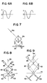
- Figure 6 (a) and (b) show waveforms at outputs of the signal detectors shown in Figure 3;
- Fig. 7 is a side view showing an example of the concrete construction of the photodetectors shown in Fig. 3;
- Fig. 8 is a scheme for explaining the working principle of an optical instrument for measuring displacement according to this invention;
- Figs. 9 and 10 are schemes for explaining the same working principle as that of Fig. 8 for two different cases;
- Fig. 11 is a s.cheme for explaini-ng the working principle of another optical instrument for measuring displacement according to this invention;
- Figs. 12 and 13 are schemes for explaining the same working principle as that of Fig. 11 for two different cases corresponding to Figs. 9 and 10, respectively;
- Fig. 14 is a schematical view showing the interior of a hologram used as a diffraction grating in an optical instrument for measuring displacement according to this invention;
- Fig. 15 is a perspective view showing a concrete example of.the construction of the arrangement shown in Fig. 11; and
- Fig. 16 is a block diagram showing an example of the circuit displaying the difference of the optical path lengths in the embodiment shown in Fig. 1 and generating alarm and stop signals.
- Fig. 1 is a scheme showing the construction of an optical instrument for measuring displacement according to an embodiment of this invention, in which reference numeral 1 denotes a light source consisting of a multimode semiconductor laser device: 2 is a beam splitter for splitting a light beam into two; 3 is a diffraction grating used as a scale; 4, 7 and 13 are λ/4 plates; 5 and 6 are a pair of mirrors; 8 is a half mirror; 9 and 12 are polarizing plates; and 10 and 11 are photodetectors.
- In the device constructed as described above, a light beam emerging from the multimode semiconductor laser device 1 enters the
beam splitter 2 and is split at A into two beams, which proceed further toward B and C on the diffraction grating 3. Each of the light beams entering the diffraction grating 3 is diffracted and projected through a X/4 plate 4 or 7 onto amirror 5 or 6. Each beam is reflected at D or E and enters again the diffraction grating 3. The beams diffracted again by the diffraction grating 3 return to thebeam splitter 2 and interfere therein with each other. Thereafter they are projected through thehalf mirror 8 on thephotodetectors - In general, visibility of interference fringes in an interferometer is determined by coherency of the light source and by the difference between optical path lengths of the two interfering beams. For a well coherent light source such as a laser device, in which single mode oscillation takes place, visibility is not lost, even if the difference between the two optical path lengths is great. To the contrary, in the case where a light source, whose coherency is not so good, is used, it is known that visibility of interference fringes changes, when the difference between the two optical path lengths varies.
- This invention has been made by applying this principle to the optical instrument for measuring displacement.
- In the device shown in Fig. 1, in order that no errors cannot be provoked by variation in wavelength of the mulitmode semiconductor laser device 1, it is necessary that the path A→B→D and the path A→C→E of the light beams split by the
beam splitter 2 are so adjusted that their lengths are equal. In this case, precision of this adjustment depends on temperature conditions of the environment, in which the optical system is placed. - For example, a commercialized semiconductor laser has characteristics of wavelength to temperature variation which is about 0.3nm/°C. Assuming that the range of temperature variations is ±10°C and that the wavelength is 780nm, the pitch of the diffraction grating in this optical system is approximately 0.55pm.
- Further, assuming that required precision is O.lum, the difference Δℓ between the two optical path length sould be within the range which is so determined that the relation

- λ: wavelength of the light source
- P: pitch of the grating.
- In this case, tolerance of At is about 70µm.
- In order that this difference can be monitored it is necessary to use a light source allowing to detect variations in Δℓ of this order to magnitude and moreover having suitable coherency for which visibility does not vary too much for Δℓ smaller than this value, because it is difficult to manipulate the device, when it is too sensitive to Δℓ.
- When a suitable multimode semiconductor laser device is used according to this invention, these conditions are fulfilled and it is possible to obtain variations in modulation for suitable variations in Δℓ. that is, to detect variations in difference between the two optical path lengths as variations in modulation.
- Fig. 2 is a graph showing a relation between the difference Δℓ between the two optical path lengths and the amplitude modulation of interference signals, obtained experimentally by means of a device arranged as indicated in Fig. 1.
- As can be seen in Fig. 2, it is understood that adjustment of the optical path lengths can be effected with fairly high precision.
- For an optical system having a lower precision, a multimode semiconductor laser devcie having fewer oscillation modes than that described above can be used. In this case, characteristic curves varying more slowly than that shown in Fig. 2 are obtained. When use of a single mode laser device is desired, a multimode laser device is used only during adjustment of the optical system and after completion of the adjustment, it can be replaced by the original single mode laser device.
- Furthermore, in the case where a multimode semiconductor laser device is used, when a difference between the two optical path lengths is provoked by some cause, since the difference manifests itself as lowering of output signals and can be detected, one can avoid using it without knowing that errors due to variations in wavelength are provoked. Further, since only interference between two beams having small At can be detected selectively, one can avoid interference signals which are varied by interference with unnecessary light reflected by surfaces of optical parts and thus precision can be ameliorated. In addition, since it is possible not to use non-reflection coating on optical parts, optical parts which are not expensive can be used. It is also possible to improve S/N ratio with respect to that obtained when a single mode semiconductor laser device is used.
- Fig. 16 is a block diagram showing an example of the circuit displaying the difference of the optical path lengths in the embodiment shown in Fig. 1 and generating alarm and stop signals. Detection signals obtained by using a
photodetector circuit 101 comprising thephotodetectors amplifier circuit 102 to acounter circuit 109, whose output signals drive adisplacement display circuit 110, where magnitude of the displacement is displayed. At the same time, the detection signals are sent from theamplifier circuit 102 through apeak hold circuit 107 to an optical pathdifference display circuit 108, which displays the difference between the optical path lengths of the two beams. Moreover the detection signals are sent also from theamplifier circuit 102 to asampling circuit 103, whose s.ampl- ing output signals are sent through a comparingcircuit 104 to analarm generation circuit 105, which produces alarm signals. The sampling output signals control also astopping circuit 106, which stops the devices belonging to the measuring system. - Fig. 3 is a scheme showing an example of the concrete construction of a signal detector, which can be used in a device according to this invention.
Reference numerals polarizing beam splitters - An
interference light beam 21 produced by the two beams is splitted into two, 21A and 21B, by ahalf mirror 22 and thereafter each of thesplitted beams polarizing beam splitter photodetectors photodetector 30 and components perpendicular to the sheet emerge toward thephotodetector 31. - In this case, the phases of the two interference signals differ in phase by 180° from each other and their intensities are almost equal.
- On the other hand, the relation between the two split beams coming from the light beam reflected by the
half mirror 22, passing through a X/4plate 25 and directed toward thedetectors detectors - Fig. 5 is a circuit diagram of a cancelling circuit used in the device according to this invention, in which D3 and D4 represent photodiodes and AMP denotes an amplifier. Two such cancelling circuits are disposed, corresponding to the
polarizing beam splitters - The
polarizing beam splitter 28 will be explained as . an example. The lst photodiode D3 is located at the position for thephotodetector 30 and the 2nd photodiode D4 is located at the position for thephotodetector 31. Furthermore, these lst and 2nd photodiodes D3 and D4 are connected in series, and at the same time their connecting point is connected with the input terminal of the amplifier AMP. To the 1st and 2nd diodes D3, D4 are connected reverse bias sources. - In the circuit described above, since the D.C. components of the lst and 2nd photodiodes D3, D4 are cancelled by each other at the connecting point G between them, the amplitude is doubled and large detection signals as shown in Fig. 6(a) can be obtained at the output of the amplifier AMP. Since the
polarizing beam splitter 29 acts in the same manner as that described above, large detection signals, whose phase is different by 90° from that indicated in Fig. 6(a), as shown in Fig. 6(b), can be obtained at the output terminal. - It is useful to this invention, if characteristics of the two photodiodes connected in series are identical, signals containing no unnecessary components such as D.C. component, dark current and so forth are applied to the input of the amplifier AMP and amplified with a high gain. Therefore, it is possible to obtain large output signals. Moreover, if two photodiodes are formed on the same substrate, as indicated in Figure 7, it is possible to obtain output signals having still higher quality.
- As explained above, when the signal detecting part is constructed as indicated above, large detection signals can be obtained.
- According to this invention, since D.C. components can be cancelled with few parts only by combining extremely simple optical parts with a cancelling circuit, it is possible to obtain detection signals, which are not only large but also of high quality, and thus reliability of the device is improved.
- Fig. 8 shows another example of the construction of the optical instrument for measuring displacement according to this invention, in which
reference numeral 41 represents a diffraction grating used as a scale; 42 and 43 are a pair of mirrors; 52 and 53 are another pair of mirrors; 44 is a light source; 45 is a photodetector; 54 is a beam splitter for splitting the light beam emerging from the light source into two; and 55 denotes a normal to thediffraction grating 41. - In the arrangement of the device described above the
light beam 46 emerging from thelight source 44 and projected on thebeam splitter 54 is split into two, that is, the light beam 46A directed to themirror 42 and the light beam 46B directed to themirror 43. The light beams 46A and 46B are projected through themirrors diffraction grating 41 on both sides of thenormal axis 55 with equal incident angles. Thediffraction grating 41 is so disposed that grating vector is directed horizontally on the sheet of the figure, and that the direction of the displacement to be measured of thediffraction grating 41 used as a scale coincides with the direction of the grating vector. Thus, the light beam 46A reflected by themirror 42 is further so diffracted that it is projected on themirror 52, and at the same time the light beam 46B reflected by themirror 43 is further so diffracted that it is projected on themirror 53. In this case, the incident light beams 46A and 46B are so diffracted that the optical axis of one of the diffractedlight beams - Thereafter the diffracted
light beams mirrors diffraction grating 41. Here they are again diffracted. Thus the diffractedlight beam 47A coming from themirror 52 is projected on themirror 42 and the diffractedlight beam 47B coming from themirror 53 is projected on themirror 43. They are reflected there and return to thebeam splitter 54. In thisbeam splitter 54 the optical axis of the transmitted light beam of that reflected by themirror 42 coincides with that of the reflected light beam of that reflected by themirror 43 and they interfere with each other. Therefore, the displacement of thediffraction grating 41 used as a scale is measured by detecting this interference intensity by means of thephotodetector 45. In this case the detection signals and the displacement are related as follows. - The complex amplitudes (excepting the term varying in time) E1, E2 of the two incident beams passing through the origin after having been reflected by the
mirrors 

point 0 when the original beam is split by the beam splitter into two to the moment when the split beams are projected on the diffraction grating. - Moreover, the transmission coefficient T can be expressed by the following equation.

- Putting K =·2ksinθ so that the grating vector K satisfies the diffraction condition described above, the equation (3) can be transformed as follows.

- The diffracted light beam is expressed by the product of E1, E2 and T and thus E11 and E21 representing the respective diffracted light of 1st order are expressed as follows.


- If as the grating a volume type hologram is used, almost no light appears except for the diffracted light of Oth order and that of 1st order. In this case the propagation direction of one of the two diffracted light beams coincides with the incident direction of the other and their phases differ from each other by P expressed by the following equation.

- Putting now φ3 and φ4 for phase variations of these diffracted light beams from the moment when these diffracted light beams are reflected by the
mirrors diffraction grating 41, respectively, the complex amplitudes E12, E22 of the beams just before they return to thediffraction grating 41 and are projected thereon can be expressed as follows.

- E13 and E23 being complex amplitudes of the diffracted light beams of 1st order of the beams projected again on the
diffraction grating 41 and diffracted by it, respectively, they can be calculated in the same manner as the equations mentioned above (5) and (6), as follows.

- Moreover, paying attention only to the diffracted light beams of lst order, it can be understood that they are waves propagating in the reverse direction along the same paths as that of the incident light beams.
- When these waves enter the
beam splitter 54 the light beams reflected by themirror 42 proceeds straight and on the other hand that reflected by themirror 43 is reflected so that these two beams have a same optical axis. Putting φ5 and φ6 for phase variations of the two beams till this moment, E14 and E24' which are complex amplitudes of the two beams, when they begin to interfere, can be expressed by the following equations.

- Further, interference intensity can be represented as follows.


- Examining this equation, it can be understood that phase variations, which are 4 times as great as corresponding phase variations of the scale, appear in the interference signals. Putting ℓ for the displacement of the scale, the phase of the diffraction grating Ψ can be calculated by the following equation.

- In this case, by utilizing the relation 2π=4ψ = 4·2·


- As an example, assuming X=7800A, 6=45°, and using eq. (17), L=0.78/8sin45°≒0.78/8×0.707≒0.138µm can be obtained.
- In the case where this value is assumed to be standard, dividing the period by ten and several, it is possible to measure a displacement of an order of 1/100µm. Moreover, when the optical path lengths of the two beams are equal, even if the wavelength of the light source varies, phase variations in the optical paths are also equal. Thus C=0 and interference signals which are invariant for variations in wavelength of the light source are obtained. Further, even in the case where a light source, whose range of oscillation wavelength is large and which is not well coherent, is used, if C is small, it is possible to obtain interference signals.
- In the instrument according to this invention, as it is evident from the facts mentioned above, even if the wavelength of the light source varies, the optical path lengths of the two beams vary equally. Consequently, the instrument according to this invention is so constructed that the difference between the optical path lengths C is maintained always equal to 0. This situation is kept also, when the scale (diffraction grating) moves vertically.
- Fig. 9 shows a example showing the optical paths, in which the broken lines indicate optical paths in the case where the wavelength of the
light source 44 varies. As indicated in the figure, since the optical paths of the two beams vary symmetrically, no variations in difference between the optical path lengths appear, and therefore the interference is not destroyed, because angular shifts at the end of the optical paths are also equal. - Further, although the position of the second diffraction is displaced on the diffraction grating in the figure, since the optical paths vary symmetrically in the horizontal direction with respect to those before the variation in wavelength, influences of the variations in the optical path lengths are cancelled by each other and thus they do not give rise to any phase variations in detection signals.
- Moreover, although the position of the interference beam emerging from the
beam splitter 54 is more or less displaced, when the range of variations in wavelength is small, this displacement is extremely small. In consequence, if thephotodetector 45 is sufficiently wide with respect to the displacement, no problems are produced. - Fig. 10 is a scheme where the
diffraction grating 41 is moved vertically. In this case, even if the diffraction grating is displaced from 41(A) to 41(B) and the optical paths vary as indicated by the broken lines, the position of the diffraction varies symmetrically in the same manner as for the variations in wavelength described above, influences of the vertical displacement of the diffraction grating are cancelled by each other. - Fig. 11 is a scheme showing the construction of another optical instrument for measuring displacement according to this invention, which is so constructed that the diffracted beams are reflected by a pair of
mirrors beam splitter 54 makes them interfere with each other. - Figs. 12 and 13 are schemes when variations in wavelength of the
light source 44 are produced and when thediffraction grating 41 is displaced vertically, respectively, in the device shown in Fig. 9. Since influences of these variations are cancelled by each other by the same reason as that for Figs. 10 and 11, also in these cases they do not give rise to no problems. - As other characteristics of the instrument according to this invention it can be cited that the incident angle 6 and the diffraction angle 6' of the two beams are equal. By this reason the diffraction of the two beams can satisfy, besides the grating equation consisting of


- This means that two diffractions by a grating having a grating vector in the x direction of the two beams both satisfy Bragg's condition. Consequently, it is possible to obtain a high diffraction efficiency by using a volume type hologram.
- Fig. 14 is a schematical view showing the interior of a hologram atrecording, when a volume type hologram is used, in which
reference numeral 65 denotes a coherent plane wave; 66 represents recording medium; and 67 is an enlarged view showing the interior of the hologram. The grating surface is perpendicular to the surface of the hologram. It is possible to obtain a high diffraction efficiency, which is as high as nearly 100%, by suitably selecting a material for the diffraction grating and by using a diffraction grating several µm thick. Moreover, fabrication of the scale becomes easier, because variations in grating pitch due to deformation of the material, which is often produced during the fabrication of a hologram. are small by the reason that the grating surface is perpendicular. - Fig. 15 is a perspective view showing a concrete construction of the arrangement shown in Fig. 9, in which
reference numeral 71 indicates a semiconductor laser device; 72 and 73 represent condenser lenses; 44 is a polarizing beam splitter; 75 is a grating for dividing incident wave; 76, 77 and 78 are X/4 plates; 79 and 80 are polarizing plates; 81, 82 and 83 are photodetectors for sinuous wave, for monitoring and for cosinuous wave, respectively; 84 and 85 are mirrors; and 86 is a volume type hologram scale. - For this example, a
semiconductor laser device 71 is used as a light source; a polarizing beam splitter is used as a beam splitter, and the signal light beam is separated from the incident beam by means of a 1/4 plate. Moreover, the signal light beam is divided into 3 by means of a grating so disposed that the direction of the grating vector is perpendicular to the hologram for the scale and in this manner sinuous signals, cosinous signals and monitoring signals are obtained. - In the instrument thus constructed, since a part of the incident light, which is proportional to the square of the diffraction efficiency, is obtained as signal light, for example using a scale having a diffraction efficiency of 90%, it is possible to obtain signal light having an intensisty of 80% with respect to that of the incident light. Although it is known that returning light to the semiconductor laser device gives rise to noise, there is almost no returning light in this case.
- As explained above, since an optical instrument for measuring displacement constructed as indicated above comprises a light source, a beam splitter for dividing the beam emerging from the light source into two, a diffracting grating on which these two splitted beams are projected, reflectors on which two light beams diffracted by the diffraction grating are projected and which return the diffracted light beams toward the diffraction grating, and detectors for detecting interference light of these two diffracted light beams and is so constructed that the two diffracted light beams are made interfere by the beam splitter and variations in position of the diffraction grating are obtained by measuring interference intensity by means of the detectors, following effects can be obtained:-
- 1. Variations in wavelength of the used light source do not give rise to deterioration of detection signals and measurement errors.
- 2. It is possible to effect measurements which are independent of displacements of the diffraction grating in the two directions orthogonal to the grating vector.
- 3. A diffraction grating having a high diffraction efficiency such as a volume type hologram can be used as a scale so that detection signals of high quality can be obtained.
- 4. Since it is possible to use a great angle between the diffracted light beam of Oth order and that of 1st order, resolving power is ameliorated.
- Moreover, when a multimode semiconductor laser device is used as a light source in an optical instrument for measuring displacement embodying this invention, in which a movable diffraction grating is used as a scale and displacement of the diffraction grating is measured by using interference signals of the diffracted light beams, since non-reflection coating on optical parts is unnecessary, it is possible to use optical parts which are not expensive. Furthermore S/N ratio is improved with respect to that obtained by using a single mode laser device. Besides these advantages, the following effects can be obtained:-
- 1. Since difference between the optical path length of the two beams can be detected, it is possible to effect adjustment of the optical path lengths easily with a high precision.
- 2. Since adjustment situations can be monitored, it is avoided that one effects measurements without knowing that variations in wavelength of the light source give rise to errors.
- 3. It is prevented that interference signals vary due to unnecessary light.
- 4. Moreover by constructing the detector circuit as showed in Figs. 3 and 5, it is possible to obtain large output signal and D.C. components of the signal can be cancelled with few components and with a cancelling circuit and thus more reliability is improved.
Claims (12)
Applications Claiming Priority (9)
| Application Number | Priority Date | Filing Date | Title |
|---|---|---|---|
| JP205956/83 | 1983-11-04 | ||
| JP20595683 | 1983-11-04 | ||
| JP20595683A JPS6098302A (en) | 1983-11-04 | 1983-11-04 | Optical displacement measuring device |
| JP59205854A JPS6183912A (en) | 1984-10-01 | 1984-10-01 | Signal detection mechanism for optical type displacement measuring apparatus |
| JP20585484 | 1984-10-01 | ||
| JP20585384 | 1984-10-01 | ||
| JP59205853A JPH0781884B2 (en) | 1984-10-01 | 1984-10-01 | Optical displacement measuring device |
| JP205854/84 | 1984-10-01 | ||
| JP205853/84 | 1984-10-01 |
Related Child Applications (2)
| Application Number | Title | Priority Date | Filing Date |
|---|---|---|---|
| EP88117622A Division EP0311144B1 (en) | 1983-11-04 | 1984-10-31 | Optical instrument for measuring displacement |
| EP88117622.6 Division-Into | 1988-10-22 |
Publications (4)
| Publication Number | Publication Date |
|---|---|
| EP0146244A2 true EP0146244A2 (en) | 1985-06-26 |
| EP0146244A3 EP0146244A3 (en) | 1986-08-06 |
| EP0146244B1 EP0146244B1 (en) | 1991-05-29 |
| EP0146244B2 EP0146244B2 (en) | 2002-07-03 |
Family
ID=27328553
Family Applications (2)
| Application Number | Title | Priority Date | Filing Date |
|---|---|---|---|
| EP88117622A Revoked EP0311144B1 (en) | 1983-11-04 | 1984-10-31 | Optical instrument for measuring displacement |
| EP84307484A Expired - Lifetime EP0146244B2 (en) | 1983-11-04 | 1984-10-31 | Optical instrument for measuring displacement |
Family Applications Before (1)
| Application Number | Title | Priority Date | Filing Date |
|---|---|---|---|
| EP88117622A Revoked EP0311144B1 (en) | 1983-11-04 | 1984-10-31 | Optical instrument for measuring displacement |
Country Status (3)
| Country | Link |
|---|---|
| US (1) | US4676645A (en) |
| EP (2) | EP0311144B1 (en) |
| DE (2) | DE3486178T2 (en) |
Cited By (9)
| Publication number | Priority date | Publication date | Assignee | Title |
|---|---|---|---|---|
| DE3702203A1 (en) * | 1986-01-27 | 1987-07-30 | Agency Ind Science Techn | METHOD FOR MEASURING RELATIVE MOVEMENTS |
| FR2615281A1 (en) * | 1987-05-11 | 1988-11-18 | Canon Kk | DEVICE FOR MEASURING A RELATIVE MOTION DISTANCE OF TWO MOBILE OBJECTS IN RELATION TO EACH OTHER |
| DE3923768A1 (en) * | 1988-07-19 | 1990-03-01 | Canon Kk | DISPLACEMENT MEASURING DEVICE |
| DE3931755A1 (en) * | 1988-09-22 | 1990-03-29 | Canon Kk | DIRECTIONAL SENSOR |
| EP0364984A2 (en) * | 1988-10-19 | 1990-04-25 | Canon Kabushiki Kaisha | Interferometer using multi-mode semiconductor laser |
| DE3942385A1 (en) * | 1988-12-21 | 1990-07-05 | Mitutoyo Corp | DISPLACEMENT MEASURING DEVICE OF THE INTERFERENCE GRID TYPE |
| US4975571A (en) * | 1987-12-15 | 1990-12-04 | Renishaw Plc | Opto-electronic scale-reading apparatus |
| US5198873A (en) * | 1988-10-19 | 1993-03-30 | Canon Kabushiki Kaisha | Encoder utilizing interference using multi-mode semiconductor laser |
| GB2340935A (en) * | 1998-08-20 | 2000-03-01 | Sony Precision Technology Inc | Optical displacement measurement system |
Families Citing this family (61)
| Publication number | Priority date | Publication date | Assignee | Title |
|---|---|---|---|---|
| US4967072A (en) * | 1984-09-05 | 1990-10-30 | Canon Kabushiki Kaisha | Interferometric rotating condition detection apparatus |
| JPH0621801B2 (en) * | 1985-07-03 | 1994-03-23 | キヤノン株式会社 | Rotary Encoder |
| JPS6212814A (en) * | 1985-07-10 | 1987-01-21 | Canon Inc | Rotary encoder |
| GB2185314B (en) * | 1986-01-14 | 1990-09-26 | Canon Kk | Encoder |
| DE3700777C2 (en) * | 1986-01-14 | 1994-05-05 | Canon Kk | Device for detecting the position of an object |
| DE3706277C2 (en) * | 1986-02-28 | 1995-04-27 | Canon Kk | Rotation encoder |
| US5051579A (en) * | 1987-04-03 | 1991-09-24 | Canon Kabushiki Kaisha | Optical scale encoder with light intensity alarm |
| FR2615280B1 (en) * | 1987-05-11 | 1996-07-19 | Canon Kk | DEVICE FOR MEASURING THE MOTION DISTANCE RELATIVE OF TWO MOBILE OBJECTS IN RELATION TO THE OTHER |
| JPH073344B2 (en) * | 1987-06-15 | 1995-01-18 | キヤノン株式会社 | Encoder |
| US5067813A (en) * | 1988-04-06 | 1991-11-26 | Canon Kabushiki Kaisha | Optical apparatus for measuring displacement of an object |
| JPH0718714B2 (en) * | 1988-05-10 | 1995-03-06 | キヤノン株式会社 | encoder |
| JP2567036B2 (en) * | 1988-05-10 | 1996-12-25 | キヤノン株式会社 | Optical encoder |
| JPH0778433B2 (en) * | 1988-07-19 | 1995-08-23 | キヤノン株式会社 | Rotary encoder |
| JP2586122B2 (en) * | 1988-11-18 | 1997-02-26 | キヤノン株式会社 | Rotary encoder |
| JP2629948B2 (en) * | 1989-03-03 | 1997-07-16 | キヤノン株式会社 | encoder |
| JPH02285705A (en) * | 1989-04-26 | 1990-11-26 | Canon Inc | Signal insertion circuit |
| US5146085A (en) * | 1989-05-12 | 1992-09-08 | Canon Kabushiki Kaisha | Encoder with high resolving power and accuracy |
| US5050993A (en) * | 1989-06-14 | 1991-09-24 | Rockwell International Corporation | Diffraction encoded position measuring apparatus |
| US5098190A (en) * | 1989-08-07 | 1992-03-24 | Optra, Inc. | Meterology using interferometric measurement technology for measuring scale displacement with three output signals |
| JP2683117B2 (en) * | 1989-10-31 | 1997-11-26 | キヤノン株式会社 | encoder |
| DE4006365A1 (en) * | 1990-03-01 | 1991-10-17 | Heidenhain Gmbh Dr Johannes | Position measuring device used as distance sensor - uses retroreflection to provide interfering light beams providing phase shift proportional to relative spacing |
| JPH04229702A (en) * | 1990-06-20 | 1992-08-19 | Canon Inc | Method and device for processing signal and system for displacement detector using the device |
| US5225918A (en) * | 1990-07-18 | 1993-07-06 | Sony Magnescale, Inc. | Hologram scale, apparatus for making hologram scale, moving member having hologram scale assembled hologram scale and apparatus for making assembled hologram scale |
| JP2796756B2 (en) * | 1990-08-30 | 1998-09-10 | ソニー・プレシジョン・テクノロジー株式会社 | Hologram scale |
| ES2024325A6 (en) * | 1990-10-16 | 1992-02-16 | Fagor S Coop Ltda | Displacement metering optical coder |
| US5104225A (en) * | 1991-01-25 | 1992-04-14 | Mitutoyo Corporation | Position detector and method of measuring position |
| JPH05232318A (en) * | 1991-02-19 | 1993-09-10 | Sony Magnescale Inc | Reflection type hologram scale |
| US5486923A (en) * | 1992-05-05 | 1996-01-23 | Microe | Apparatus for detecting relative movement wherein a detecting means is positioned in the region of natural interference |
| ATE182677T1 (en) * | 1992-05-05 | 1999-08-15 | Microe Inc | APPARATUS FOR DETECTING RELATIVE MOTION |
| US5432443A (en) * | 1992-06-23 | 1995-07-11 | Sony Magnescale Inc. | Linear position detector including a phase shifter and a sample-and-hold circuit for synchronizing a sample pulse period with the reference period of the equilibrium modulated signal |
| JP3232795B2 (en) * | 1992-08-06 | 2001-11-26 | キヤノン株式会社 | Detector |
| US5424829A (en) * | 1992-09-02 | 1995-06-13 | Mitutoyo Corporation | Apparatus wherein diffracted light does not return to the source |
| JP2557171B2 (en) * | 1992-11-25 | 1996-11-27 | 株式会社ミツトヨ | Displacement detection device |
| US5317385A (en) * | 1992-12-16 | 1994-05-31 | Federal Products Corporation | Portable extended life metrology system for measuring scale displacement with three output signals using a pulsed source |
| JPH074993A (en) * | 1993-03-23 | 1995-01-10 | Ricoh Co Ltd | Encoder apparatus |
| DE4337005C2 (en) * | 1993-10-29 | 2000-11-02 | Heidenhain Gmbh Dr Johannes | Length or angle measuring device |
| US5507455A (en) * | 1993-12-28 | 1996-04-16 | Yang; Ro-King | Automatic control device for flying state of remote-control toy airplane |
| JP3531375B2 (en) * | 1996-09-03 | 2004-05-31 | ソニー・プレシジョン・テクノロジー株式会社 | Displacement detector |
| US6407815B2 (en) * | 1998-07-02 | 2002-06-18 | Sony Precision Technology Inc. | Optical displacement measurement system |
| WO2000071968A1 (en) | 1999-05-24 | 2000-11-30 | Brimrose Corporation Of America | Device and method for optical path length measurement |
| DE50015787D1 (en) | 1999-09-16 | 2009-12-24 | Heidenhain Gmbh Dr Johannes | Device for position determination and determination of guide errors |
| AU2001292726A1 (en) * | 2000-09-19 | 2002-04-02 | Microesystems, Inc. | Interface component a positioning system and method for designing an interface component |
| JP4077637B2 (en) | 2002-02-25 | 2008-04-16 | 株式会社ミツトヨ | Grating interference displacement measuring device |
| US20030174343A1 (en) * | 2002-03-18 | 2003-09-18 | Mitutoyo Corporation | Optical displacement sensing device with reduced sensitivity to misalignment |
| US6879405B2 (en) * | 2002-11-18 | 2005-04-12 | Sony Precision Technology, Inc. | Displacement pickup |
| DE102004053082A1 (en) * | 2004-11-03 | 2006-05-04 | Dr. Johannes Heidenhain Gmbh | Position measuring system |
| JP4722474B2 (en) | 2004-12-24 | 2011-07-13 | 株式会社ミツトヨ | Displacement detector |
| JP4670438B2 (en) * | 2005-04-01 | 2011-04-13 | ソニー株式会社 | How to provide content and its playlist |
| DE102005025385B4 (en) * | 2005-04-20 | 2007-03-22 | Von Ardenne Anlagentechnik Gmbh | Vacuum coating system for coating flat substrates with a measuring device for transmission or / and reflection measurement |
| US8233154B2 (en) | 2005-12-22 | 2012-07-31 | Board Of Supervisors Of Louisiana State University And Agricultural And Mechanical College | High precision code plates and geophones |
| US8300233B2 (en) | 2010-03-30 | 2012-10-30 | Zygo Corporation | Interferometric encoder systems |
| DE102010041556A1 (en) | 2010-09-28 | 2012-03-29 | Carl Zeiss Smt Gmbh | Projection exposure apparatus for microlithography and method for microlithographic imaging |
| JP5849103B2 (en) | 2011-02-01 | 2016-01-27 | ザイゴ コーポレーションZygo Corporation | Interferometric heterodyne optical encoder system |
| JP5905729B2 (en) * | 2011-10-26 | 2016-04-20 | Dmg森精機株式会社 | Displacement detector |
| TWI516746B (en) | 2012-04-20 | 2016-01-11 | 賽格股份有限公司 | Method, apparatus, and computer-program product for performing non-harmonic cyclic error compensation in interferometric encoder systems and lithography systems |
| JP6427399B2 (en) * | 2014-04-14 | 2018-11-21 | Dmg森精機株式会社 | Displacement detection device |
| CN104048597B (en) * | 2014-06-13 | 2017-06-13 | 中国科学院上海光学精密机械研究所 | Self adaptation common light path grating interferometer and its implementation |
| CN105066908B (en) * | 2015-08-12 | 2017-06-09 | 北京航空航天大学 | A kind of digital hologram three-dimensional Shape measure device based on multi-wavelength and multi-polarization state |
| JP6896973B2 (en) * | 2018-06-20 | 2021-06-30 | エルジー・ケム・リミテッド | A composition for polyamide interfacial polymerization and a method for producing a water treatment separation membrane using the composition. |
| DE102019201699A1 (en) | 2019-02-11 | 2019-04-04 | Carl Zeiss Smt Gmbh | Optical sensor for a projection exposure apparatus for semiconductor lithography and projection exposure apparatus |
| DE102020118659A1 (en) * | 2019-07-17 | 2021-01-21 | Dmg Mori Co., Ltd. | DETECTION DEVICE |
Citations (2)
| Publication number | Priority date | Publication date | Assignee | Title |
|---|---|---|---|---|
| WO1979000433A1 (en) * | 1977-12-23 | 1979-07-12 | Remijan W | Optical apparatus and method for producing same |
| EP0065429A1 (en) * | 1981-04-16 | 1982-11-24 | Euromask | Method and apparatus for the optical measurement of displacement, and its application to step and repeat photoreproduction |
Family Cites Families (3)
| Publication number | Priority date | Publication date | Assignee | Title |
|---|---|---|---|---|
| DE2003492A1 (en) * | 1970-01-27 | 1971-08-12 | Leitz Ernst Gmbh | Measuring method for step encoders for measuring lengths or angles as well as arrangements for carrying out this measuring method |
| US3738753A (en) * | 1970-09-21 | 1973-06-12 | Holograf Corp | Interferometer utilizing gratings to measure motion |
| GB1367886A (en) * | 1971-10-29 | 1974-09-25 | Ti Group Serivces Ltd | Measuring apparatus |
-
1984
- 1984-10-31 DE DE88117622T patent/DE3486178T2/en not_active Revoked
- 1984-10-31 EP EP88117622A patent/EP0311144B1/en not_active Revoked
- 1984-10-31 EP EP84307484A patent/EP0146244B2/en not_active Expired - Lifetime
- 1984-10-31 DE DE8484307484T patent/DE3484649D1/en not_active Expired - Lifetime
- 1984-11-05 US US06/668,097 patent/US4676645A/en not_active Expired - Lifetime
Patent Citations (2)
| Publication number | Priority date | Publication date | Assignee | Title |
|---|---|---|---|---|
| WO1979000433A1 (en) * | 1977-12-23 | 1979-07-12 | Remijan W | Optical apparatus and method for producing same |
| EP0065429A1 (en) * | 1981-04-16 | 1982-11-24 | Euromask | Method and apparatus for the optical measurement of displacement, and its application to step and repeat photoreproduction |
Cited By (14)
| Publication number | Priority date | Publication date | Assignee | Title |
|---|---|---|---|---|
| DE3702203A1 (en) * | 1986-01-27 | 1987-07-30 | Agency Ind Science Techn | METHOD FOR MEASURING RELATIVE MOVEMENTS |
| US4815850A (en) * | 1986-01-27 | 1989-03-28 | Agency Of Industrial Science And Technology | Relative-displacement measurement method |
| FR2615281A1 (en) * | 1987-05-11 | 1988-11-18 | Canon Kk | DEVICE FOR MEASURING A RELATIVE MOTION DISTANCE OF TWO MOBILE OBJECTS IN RELATION TO EACH OTHER |
| US4975571A (en) * | 1987-12-15 | 1990-12-04 | Renishaw Plc | Opto-electronic scale-reading apparatus |
| DE3923768A1 (en) * | 1988-07-19 | 1990-03-01 | Canon Kk | DISPLACEMENT MEASURING DEVICE |
| DE3931755A1 (en) * | 1988-09-22 | 1990-03-29 | Canon Kk | DIRECTIONAL SENSOR |
| EP0364984A3 (en) * | 1988-10-19 | 1990-06-13 | Canon Kabushiki Kaisha | Interferometer using multi-mode semiconductor laser |
| EP0364984A2 (en) * | 1988-10-19 | 1990-04-25 | Canon Kabushiki Kaisha | Interferometer using multi-mode semiconductor laser |
| US5198873A (en) * | 1988-10-19 | 1993-03-30 | Canon Kabushiki Kaisha | Encoder utilizing interference using multi-mode semiconductor laser |
| DE3942385A1 (en) * | 1988-12-21 | 1990-07-05 | Mitutoyo Corp | DISPLACEMENT MEASURING DEVICE OF THE INTERFERENCE GRID TYPE |
| GB2227558B (en) * | 1988-12-21 | 1993-01-06 | Mitutoyo Corp | Grating-interference type displacement meter apparatus |
| DE3942385B4 (en) * | 1988-12-21 | 2005-08-25 | Mitutoyo Corp. | Grating displacement meter |
| GB2340935A (en) * | 1998-08-20 | 2000-03-01 | Sony Precision Technology Inc | Optical displacement measurement system |
| GB2340935B (en) * | 1998-08-20 | 2003-08-27 | Sony Prec Technology Inc | Optical displacement measurement system |
Also Published As
| Publication number | Publication date |
|---|---|
| DE3486178T2 (en) | 1993-10-21 |
| DE3484649D1 (en) | 1991-07-04 |
| EP0146244A3 (en) | 1986-08-06 |
| EP0311144A3 (en) | 1991-02-06 |
| US4676645A (en) | 1987-06-30 |
| EP0146244B2 (en) | 2002-07-03 |
| DE3486178D1 (en) | 1993-08-19 |
| EP0311144A2 (en) | 1989-04-12 |
| EP0146244B1 (en) | 1991-05-29 |
| EP0311144B1 (en) | 1993-07-14 |
Similar Documents
| Publication | Publication Date | Title |
|---|---|---|
| EP0146244B1 (en) | Optical instrument for measuring displacement | |
| JP2673086B2 (en) | Method and apparatus for interferometrically determining the phase difference between differently polarized light beams | |
| JPH04270920A (en) | Position detector and position detecting method | |
| EP1707924A2 (en) | Displacement detection apparatus, displacement measuring apparatus and fixed point detection apparatus | |
| US5574560A (en) | Dual-beam interferometer with a phase grating | |
| US5127733A (en) | Integrated optical precision measuring device | |
| JPH04184218A (en) | Optical type position detector | |
| EP0611438A1 (en) | Measuring instruments. | |
| US5717488A (en) | Apparatus for measuring displacement using first and second detecting means for measuring linear and rotary motion | |
| US5929989A (en) | Optical pressure detection method and apparatus | |
| JP3395339B2 (en) | Fixed point detector | |
| US5067813A (en) | Optical apparatus for measuring displacement of an object | |
| GB2342990A (en) | Reflection type hologram scale for optical displacement measuring apparatus | |
| JPH0781884B2 (en) | Optical displacement measuring device | |
| JPH0235248B2 (en) | ||
| JP3428129B2 (en) | Fixed point detector | |
| JPH0472163B2 (en) | ||
| JP3358286B2 (en) | Fixed point detector | |
| EP0506357A2 (en) | Optical voltage detector | |
| KR940011274B1 (en) | Wave change measuring apparatus of laser diode | |
| JPH05126603A (en) | Grating interference measuring device | |
| KR100248195B1 (en) | Apparatus for measuring displacement and method using the same | |
| JPS62274216A (en) | Method and instrument for measuring fine displacement | |
| JP3161879B2 (en) | Angle measuring method and device | |
| JPH11295029A (en) | Displacement measuring apparatus |
Legal Events
| Date | Code | Title | Description |
|---|---|---|---|
| PUAI | Public reference made under article 153(3) epc to a published international application that has entered the european phase |
Free format text: ORIGINAL CODE: 0009012 |
|
| 17P | Request for examination filed |
Effective date: 19841108 |
|
| AK | Designated contracting states |
Designated state(s): CH DE GB LI NL |
|
| PUAL | Search report despatched |
Free format text: ORIGINAL CODE: 0009013 |
|
| RHK1 | Main classification (correction) |
Ipc: G01B 9/02 |
|
| AK | Designated contracting states |
Kind code of ref document: A3 Designated state(s): CH DE GB LI NL |
|
| 17Q | First examination report despatched |
Effective date: 19880408 |
|
| RAP1 | Party data changed (applicant data changed or rights of an application transferred) |
Owner name: SONY MAGNESCALE INC. |
|
| GRAA | (expected) grant |
Free format text: ORIGINAL CODE: 0009210 |
|
| AK | Designated contracting states |
Kind code of ref document: B1 Designated state(s): CH DE GB LI NL |
|
| XX | Miscellaneous (additional remarks) |
Free format text: TEILANMELDUNG 88117622.6 EINGEREICHT AM 31/10/84. |
|
| REF | Corresponds to: |
Ref document number: 3484649 Country of ref document: DE Date of ref document: 19910704 |
|
| PLBI | Opposition filed |
Free format text: ORIGINAL CODE: 0009260 |
|
| 26 | Opposition filed |
Opponent name: CANON KABUSHIKI KAISHA Effective date: 19920227 |
|
| NLR1 | Nl: opposition has been filed with the epo |
Opponent name: CANON KABUSHIKI KAISHA. |
|
| NLT2 | Nl: modifications (of names), taken from the european patent patent bulletin |
Owner name: SONY MAGNESCALE, INC. |
|
| PLAW | Interlocutory decision in opposition |
Free format text: ORIGINAL CODE: EPIDOS IDOP |
|
| APAC | Appeal dossier modified |
Free format text: ORIGINAL CODE: EPIDOS NOAPO |
|
| APAE | Appeal reference modified |
Free format text: ORIGINAL CODE: EPIDOS REFNO |
|
| PLAW | Interlocutory decision in opposition |
Free format text: ORIGINAL CODE: EPIDOS IDOP |
|
| APAC | Appeal dossier modified |
Free format text: ORIGINAL CODE: EPIDOS NOAPO |
|
| APAC | Appeal dossier modified |
Free format text: ORIGINAL CODE: EPIDOS NOAPO |
|
| PLAW | Interlocutory decision in opposition |
Free format text: ORIGINAL CODE: EPIDOS IDOP |
|
| REG | Reference to a national code |
Ref country code: GB Ref legal event code: IF02 |
|
| RAP2 | Party data changed (patent owner data changed or rights of a patent transferred) |
Owner name: SONY PRECISION TECHNOLOGY INC. |
|
| NLT2 | Nl: modifications (of names), taken from the european patent patent bulletin |
Owner name: SONY PRECISION TECHNOLOGY INC. |
|
| APAC | Appeal dossier modified |
Free format text: ORIGINAL CODE: EPIDOS NOAPO |
|
| PUAH | Patent maintained in amended form |
Free format text: ORIGINAL CODE: 0009272 |
|
| STAA | Information on the status of an ep patent application or granted ep patent |
Free format text: STATUS: PATENT MAINTAINED AS AMENDED |
|
| 27A | Patent maintained in amended form |
Effective date: 20020703 |
|
| AK | Designated contracting states |
Kind code of ref document: B2 Designated state(s): CH DE GB LI NL |
|
| XX | Miscellaneous (additional remarks) |
Free format text: TEILANMELDUNG 88117622.6 EINGEREICHT AM 31/10/84. |
|
| REG | Reference to a national code |
Ref country code: CH Ref legal event code: AEN Free format text: AUFRECHTERHALTUNG DES PATENTES IN GEAENDERTER FORM |
|
| REG | Reference to a national code |
Ref country code: CH Ref legal event code: PUE Owner name: SONY MAGNESCALE INCORPORATION TRANSFER- SONY PRECI |
|
| NLR2 | Nl: decision of opposition | ||
| NLR3 | Nl: receipt of modified translations in the netherlands language after an opposition procedure | ||
| EN | Fr: translation not filed | ||
| PGFP | Annual fee paid to national office [announced via postgrant information from national office to epo] |
Ref country code: CH Payment date: 20031020 Year of fee payment: 20 |
|
| PGFP | Annual fee paid to national office [announced via postgrant information from national office to epo] |
Ref country code: GB Payment date: 20031029 Year of fee payment: 20 |
|
| PGFP | Annual fee paid to national office [announced via postgrant information from national office to epo] |
Ref country code: NL Payment date: 20031031 Year of fee payment: 20 |
|
| PGFP | Annual fee paid to national office [announced via postgrant information from national office to epo] |
Ref country code: DE Payment date: 20031219 Year of fee payment: 20 |
|
| PG25 | Lapsed in a contracting state [announced via postgrant information from national office to epo] |
Ref country code: LI Free format text: LAPSE BECAUSE OF EXPIRATION OF PROTECTION Effective date: 20041030 Ref country code: GB Free format text: LAPSE BECAUSE OF EXPIRATION OF PROTECTION Effective date: 20041030 Ref country code: CH Free format text: LAPSE BECAUSE OF EXPIRATION OF PROTECTION Effective date: 20041030 |
|
| PG25 | Lapsed in a contracting state [announced via postgrant information from national office to epo] |
Ref country code: NL Free format text: LAPSE BECAUSE OF EXPIRATION OF PROTECTION Effective date: 20041031 |
|
| REG | Reference to a national code |
Ref country code: GB Ref legal event code: PE20 |
|
| REG | Reference to a national code |
Ref country code: CH Ref legal event code: PL |
|
| NLV7 | Nl: ceased due to reaching the maximum lifetime of a patent |
Effective date: 20041031 |
|
| APAH | Appeal reference modified |
Free format text: ORIGINAL CODE: EPIDOSCREFNO |