EP0149250A2 - Verteilergestell für Glasfaser-Kabelenden - Google Patents
Verteilergestell für Glasfaser-Kabelenden Download PDFInfo
- Publication number
- EP0149250A2 EP0149250A2 EP84116438A EP84116438A EP0149250A2 EP 0149250 A2 EP0149250 A2 EP 0149250A2 EP 84116438 A EP84116438 A EP 84116438A EP 84116438 A EP84116438 A EP 84116438A EP 0149250 A2 EP0149250 A2 EP 0149250A2
- Authority
- EP
- European Patent Office
- Prior art keywords
- couplings
- cable
- distribution frame
- individual
- frame according
- Prior art date
- Legal status (The legal status is an assumption and is not a legal conclusion. Google has not performed a legal analysis and makes no representation as to the accuracy of the status listed.)
- Granted
Links
- 239000003365 glass fiber Substances 0.000 title claims abstract description 39
- 230000008878 coupling Effects 0.000 claims abstract description 38
- 238000010168 coupling process Methods 0.000 claims abstract description 38
- 238000005859 coupling reaction Methods 0.000 claims abstract description 38
- 238000011156 evaluation Methods 0.000 claims abstract 2
- 239000000835 fiber Substances 0.000 claims description 33
- 230000001681 protective effect Effects 0.000 claims description 4
- 238000013461 design Methods 0.000 description 6
- RYGMFSIKBFXOCR-UHFFFAOYSA-N Copper Chemical compound [Cu] RYGMFSIKBFXOCR-UHFFFAOYSA-N 0.000 description 3
- 229910052802 copper Inorganic materials 0.000 description 3
- 239000010949 copper Substances 0.000 description 3
- 238000012544 monitoring process Methods 0.000 description 3
- 239000013307 optical fiber Substances 0.000 description 3
- 238000005476 soldering Methods 0.000 description 3
- 101100390736 Danio rerio fign gene Proteins 0.000 description 2
- 101100390738 Mus musculus Fign gene Proteins 0.000 description 2
- 239000004020 conductor Substances 0.000 description 2
- 238000005516 engineering process Methods 0.000 description 2
- 230000001939 inductive effect Effects 0.000 description 2
- 238000004519 manufacturing process Methods 0.000 description 2
- 238000003466 welding Methods 0.000 description 2
- 238000004891 communication Methods 0.000 description 1
- 238000010276 construction Methods 0.000 description 1
- 238000011161 development Methods 0.000 description 1
- 238000003780 insertion Methods 0.000 description 1
- 230000037431 insertion Effects 0.000 description 1
- 238000012806 monitoring device Methods 0.000 description 1
- 238000012549 training Methods 0.000 description 1
Images


Classifications
-
- G—PHYSICS
- G02—OPTICS
- G02B—OPTICAL ELEMENTS, SYSTEMS OR APPARATUS
- G02B6/00—Light guides; Structural details of arrangements comprising light guides and other optical elements, e.g. couplings
- G02B6/24—Coupling light guides
- G02B6/36—Mechanical coupling means
- G02B6/38—Mechanical coupling means having fibre to fibre mating means
- G02B6/3807—Dismountable connectors, i.e. comprising plugs
- G02B6/3833—Details of mounting fibres in ferrules; Assembly methods; Manufacture
- G02B6/3847—Details of mounting fibres in ferrules; Assembly methods; Manufacture with means preventing fibre end damage, e.g. recessed fibre surfaces
- G02B6/3849—Details of mounting fibres in ferrules; Assembly methods; Manufacture with means preventing fibre end damage, e.g. recessed fibre surfaces using mechanical protective elements, e.g. caps, hoods, sealing membranes
-
- G—PHYSICS
- G02—OPTICS
- G02B—OPTICAL ELEMENTS, SYSTEMS OR APPARATUS
- G02B6/00—Light guides; Structural details of arrangements comprising light guides and other optical elements, e.g. couplings
- G02B6/44—Mechanical structures for providing tensile strength and external protection for fibres, e.g. optical transmission cables
- G02B6/4439—Auxiliary devices
- G02B6/444—Systems or boxes with surplus lengths
- G02B6/44528—Patch-cords; Connector arrangements in the system or in the box
-
- G—PHYSICS
- G02—OPTICS
- G02B—OPTICAL ELEMENTS, SYSTEMS OR APPARATUS
- G02B6/00—Light guides; Structural details of arrangements comprising light guides and other optical elements, e.g. couplings
- G02B6/44—Mechanical structures for providing tensile strength and external protection for fibres, e.g. optical transmission cables
- G02B6/4401—Optical cables
- G02B6/4415—Cables for special applications
- G02B6/4416—Heterogeneous cables
-
- G—PHYSICS
- G02—OPTICS
- G02B—OPTICAL ELEMENTS, SYSTEMS OR APPARATUS
- G02B6/00—Light guides; Structural details of arrangements comprising light guides and other optical elements, e.g. couplings
- G02B6/44—Mechanical structures for providing tensile strength and external protection for fibres, e.g. optical transmission cables
- G02B6/4439—Auxiliary devices
- G02B6/444—Systems or boxes with surplus lengths
- G02B6/4452—Distribution frames
- G02B6/44526—Panels or rackmounts covering a whole width of the frame or rack
-
- G—PHYSICS
- G02—OPTICS
- G02B—OPTICAL ELEMENTS, SYSTEMS OR APPARATUS
- G02B6/00—Light guides; Structural details of arrangements comprising light guides and other optical elements, e.g. couplings
- G02B6/44—Mechanical structures for providing tensile strength and external protection for fibres, e.g. optical transmission cables
- G02B6/4439—Auxiliary devices
- G02B6/444—Systems or boxes with surplus lengths
- G02B6/4453—Cassettes
- G02B6/4454—Cassettes with splices
-
- G—PHYSICS
- G02—OPTICS
- G02B—OPTICAL ELEMENTS, SYSTEMS OR APPARATUS
- G02B6/00—Light guides; Structural details of arrangements comprising light guides and other optical elements, e.g. couplings
- G02B6/44—Mechanical structures for providing tensile strength and external protection for fibres, e.g. optical transmission cables
- G02B6/4439—Auxiliary devices
- G02B6/444—Systems or boxes with surplus lengths
- G02B6/4453—Cassettes
- G02B6/4455—Cassettes characterised by the way of extraction or insertion of the cassette in the distribution frame, e.g. pivoting, sliding, rotating or gliding
Definitions
- the present invention relates to a distribution frame for fiber optic cable ends.
- racks are needed similar to cable end racks of conventional communication cables, the ends, i.e. the individual glass fibers, which form a glass fiber cable in bundles, to the individual receiving or demodulating devices.
- fiber optic couplings which operate the two ends of two fiber optic cables, e.g. also connect with one another from a cable end and a connecting line in the form of a so-called pigtail.
- These fiber-optic couplings which are manufactured with very high manufacturing costs, should therefore only be used in a distribution frame where it is actually necessary to cut the light path.
- the object of the invention is therefore to provide a distribution frame for fiber optic cable ends for dividing the fiber bundle or the individual glass fibers of a fiber optic cable, in which in addition to the connection of the cable ends with connecting lines fiber optic couplings can be easily accessible in a quantity corresponding to the number of glass fibers , in which the individual fiber optic couplings are accessible without impairing the other fiber optic couplings, a cable routing is guaranteed which manages with very few bends with a relatively large radius despite a small space requirement and which guarantees easy handling.
- the frame is divided into at least two sections divides, namely a receiving area for receiving the splice connections between the individual glass fibers of the cable and the first flexible connecting lines and in an area for receiving the glass fiber couplings, the couplings being kept free of the ends of the first flexible connecting lines in the form of so-called pigtails in that this are held in a clamp even near the end that is inserted into the coupling, each individual fiber in a separate clamp.
- the cables are routed in such a way that, for example, the glass fiber bundles are first inserted into the frame from below or from above, and the individual fibers are spliced (welded) to one end of the first connecting lines in the lower region, and the splice connection in this region is preferably stored in magazines will. From these magazines, i.e. So from the lower receiving area, the first connection lines are gem. an advantageous embodiment of the invention on one side of the distributor frame up in the area of the glass fiber couplings.
- the individual terminals for holding the free ends of the first connecting lines, through which the individual ends of the first connecting lines are inserted are provided one above the other, to the extent that there is only a short free end on the rear of the terminals, onto which the couplings are plugged with an insertion side.
- the short free ends of the individual glass fibers are so stable that the couplings are carried freely.
- the clamps themselves are arranged one behind the other, as seen from the bottom up, with a clamp opening slightly inclined in the direction of the information flow going upwards.
- This measure ensures that a clamp must first be provided for each possible cable end in the manufacture and equipment of the frame, but that couplings in a frame are only required in the number of glass fiber ends that are actually later pulled into the frame. Furthermore, this arrangement guarantees that the first connecting leads leading from the bottom up on one side of the frame only need to be bent slightly in order to be able to be inserted into the individual terminals and that the second connecting leads then also connect to the couplings So-called pigtails, only have to have a corresponding curvature in the opposite direction in order to then be led out of the frame to the actual end frame.
- the clamp surfaces preferably being of polygonal shape in order to secure the glass fibers introduced in detail with their sheathing against twisting even with only slight pressure. This is important because couplings are placed on the free ends of the connection lines that look through the terminals, on which occasionally a certain torque is exerted when loosening and connecting, but this should not lead to a twisting of the glass fiber connection lines and may.
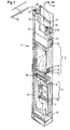
- FIGS. 1 and 2 explains the basic structure of a distribution frame for fiber optic cable ends with some details and design options.
- a glass fiber cable 10 is divided at the entrance to the distribution frame 1 into corresponding fiber bundles 11, which are initially held together by an elastic hose (not shown).
- a holder 12 is provided in order to relieve the cable itself of any train.
- the electrical conductors 13, which are generally carried in a glass fiber cable for monitoring and measuring purposes, are led out of the bundle behind this holder,
- the glass fiber bundles 11 are laterally guided all the way down in the frame, where they are guided into bundles for bundles 3 in bundles in bundles 3.
- magazines 3 which are removable per se and which are each equipped with the number of fibers in a bundle, for example with 12 pockets, are spliced with first connecting lines 7, i.e.
- the welds between the cable end and the first connecting lines 7 are accommodated in the magazines.
- the magazines can be removed individually, and accordingly a large loop of the cable end 11 and the first connecting lines 7 must be provided.
- the actual coupling insert 5 is provided above the receiving area for the splice connections.
- terminals 8 are provided, into which the first connecting lines are guided, ie through which the free ends of the first connecting lines are inserted and clamped.
- the individual glass fiber couplings 6 are plugged onto the rear of the terminals 8 and on the side facing away from the terminals 8 the couplings 6 then open the free ends of second connecting lines 9th
- soldering insert is then provided in the exemplary embodiment shown with a prewired socket field 13, a nameplate 14, soldering lugs 15 and a holder 16 for the copper lines 6.
- These links serve for an additional Monitoring and data exchange. via the copper lines 13, which are carried, for example, in the glass fiber cable 10, as mentioned.
- the final wiring of such a distribution frame is done by first removing the sheath from the optical fiber cable over a length corresponding to the height of the frame plus the length corresponding to the guide in the receiving area for the splice connections. In the upper region of curvature, a flexible tube is then pushed over the fiber bundles opened in this way, and with the aid of the flexible tube, the tube and fiber bundle unit is fastened to the holder for the flexible hose 12, a cable tie. The individual fiber bundles are then laid down in the space specially provided in the left area and in turn secured to a holder for the fiber bundles 18. The ends of the fiber bundles are then exposed and guided into the individual magazines 3 and, if necessary, held over further cable ties 19 when these magazines enter.
- This first flexible connecting line is inserted into the corresponding terminals 8 and initially had there.
- these first flexible connecting lines 4 can be spliced to the ends of the optical fibers by removing the individual magazines 3 and can be stored in the individual pockets to be provided in the magazines, taking into account a minimum radius.
- the second flexible connecting lines 9 are then introduced from above and guided in the appropriate length to the individual couplings 6 placed on free ends of the first flexible connecting lines 4.
- the connecting lines 9 emerging at the top are held together in a holder 17 and then routed together to correspondingly provided cable ducts.
- the copper wires 13 are laid to the upper soldering insert in a manner known per se.
- these clamps 8 are fastened to the front of a holding plate 31 inserted into the frame near the center.
- the holding plate 31 is provided on the side adjacent to the rear wall of the frame with a bent foot 32, via which the holding plate is permanently fixed, for example by spot welding points 33.
- the front edge of the holding plate 31 is cut in at the side and the tabs 34 thus formed are seen in the plan view in FIG. 2, angled to the right at an angle, so that they are slightly inclined with respect to the vertical extent of the frame.
- the clamps 8 are then attached to these individual tabs 34 in such a way that the through openings for the free ends of the first flexible connecting lines are inclined slightly upward, as in FIGS. 1 and 2 also indicated.
- the holding plate it is advisable not to design the holding plate as a unit for the entire receiving space for the couplings, but in several pieces, for example by assigning about 10 terminals to each individual holding plate.
- FIGS. 6 and 7 An embodiment with a basic structure for such a clamp is shown in FIGS. 6 and 7 are shown schematically.
- the terminal 8 shown in FIG. 6 in side view and in FIG. 7 in plan view of the actuation push button has an essentially cuboid base body 41 with an approximately square cross section, in which an opening 62 is provided for pushing through the free end of a connecting line.
- the opening 65 present in this pressure piece is shifted onto a pressure piece 64 by means of finger pressure until both openings are aligned. In this state, the free end of an optical fiber line can then be inserted.
- the glass fiber is then clamped in by the force of the spring 63, the shape of the opening 65 having a trapezoidal cross section ensuring good securing of the glass fiber against rotation.
- each clamp 8 is assigned a protective sleeve 66 on a flexible holding cord which is always plugged onto a free glass fiber end when one end is released via the coupling. This is particularly important during assembly if initially only the ends of all flexible connecting lines are plugged in, while by no means all lines have yet to be fully occupied and have to be continued via couplings.
- Such protective sleeves are well known in connection with glass fiber technology and are not the subject of the present invention. It is only essential for the present invention that they are provided in a fixed location where they are constantly required in later operation.
- the present invention has been described in great detail in the interests of traceability by those skilled in the art.
- the cable routing is essential and of fundamental importance for the reasons mentioned in the introduction.
- the construction of clamps, the arrangement of the clamps, if necessary, in several parallel planes side by side or one behind the other, as well as the design and arrangement of cable ties, holders for individual cables, etc. is within the scope of professional skill and can be implemented on a case-by-case basis.
- the present invention enables for the first time a line routing with access to all individual couplings, in which the conditions imposed on the fiber optic technology can be met.
Abstract
Description
- Die vorliegende Erfindung bezieht sich auf ein Verteilergestell für Glasfaser-Kabelenden. Derartige Gestelle werden ähnlich wie Kabelendgestelle herkömmlicher Nachrichtenkabel benötigt, die Enden, d.h. die einzelnen Glasfasern, die in Bündeln zusammengefaßt ein Glasfaser-Kabel bilden, den einzelnen Emfangs- bzw. Demodulationseinrichtungen zuzuführen.
- Die Besonderheit bei einem derartigen Verteilergestell für Glasfaser- Kabelenden gegenüber anderen Verteiler- oder Rangiergestetlen für übliche elektrische Kabel liegt einmal darin, daß eine Informationsabnahme der einzelnen Kabelfasern für Meß- und Oberwachungszwecke nicht wie bei elektrischen Kabeln durch einen Parallelanschluß beziehungsweise eine induktive Auskopplung möglich ist, sondern daß in jedem Fall der Glasfaserweg aufgetrennt werden muß, um den über die Glasfaser geleiteten Informationsfluß dem Meß- bzw. Oberwachungsgerät zukommen zu lassen.
- Zu diesem Zweck sind Glasfaserkupplungen bekannt geworden, die mit höchster Präzision die zwei Enden von zwei Glasfaserleitungen, z.B. auch von einem Kabelende und einer Anschlußleitung in Form eines sog. Pigtails miteinander verbinden. Diese mit sehr hohem Fertigungsaufwand hergestellten Glasfaserkupplungen sollen deshalb in einem Verteilergestell nur dort eingesetzt werden, wo tatsächlich ein Auftrennen des Lichtwegs notwendig ist.
- Eine weitere Besonderheit eines derartigen Gestells besteht darin, daß die einzelnen Glasfaserleitungen, obwohl es ihre Biegsamkeit zulassen würde, nur möglichst wenig gekrümmt werden sollen, da im Gegensatz zu elektrischen Leitern die Dämpfung in den Kabeladern abhängig von der Verlegung bzw. den einzelnen Krümmungsradien ist. Während also bei einem Verteilergestell für die Ader eines elektrischen Kabels nur dafür zu sorgen ist, daß die einzelnen Leitungen nicht in Spulenform verlegt werden, da hierdurch ein überhöhter induktiver Widerstand entstehen würde, muß bei einem Verteilergestell für Glasfaserkabelenden eine Anordnung getroffen werden, bei der trotz der Anordnung von Kupplungen eine möglichst geradlinige Führung des Informationsflusses vom Kabelende zu weiteren Anschlußleitungen garantiert ist.
- Umgekehrt steht für derartige Verteilergestelle nicht ein beliebig großer Raum zur Verfügung, wobei zu berücksichtigen ist, daß im Allgemeinen etwa 10 Glasfasern zu einem Bündel und wiederum 7 - 10 Bündel zu einem Kabel zusammengefaßt sind und dementsprechend in einem oder zumindest in wenigen Gestellen verteilt und mit Anschlußleitungen gekoppelt werden müssen.
- Aufgabe der Erfindung ist es somit ein Verteilergestell für Glasfaser- Kabelenden zur Aufteilung der Faserbündel bzw. der einzelnen Glasfasern eines Glasfaser-Kabels anzugeben, bei dem außer dem Anschluß der Kabelenden mit Anschlußleitungen Glasfaserkupplungen in einer der Zahl der Glasfasern entsprechenden Menge leicht zugänglich untergebracht werden können, bei dem die einzelnen Glasfaserkupplungen ohne Beeinträchtigung der anderen Glasfaserkupplungen zugänglich sind, eine Leitungsführung garantiert ist, die mit ganz wenigen Krümmungen mit relativ großem Radius trotz geringen Platzbedarfes auskommt und bei dem eine einfache Handhabung garantiert ist.
- Diese Aufgabe wird bei einem Verteilergestell für Glasfaser-Kabelenden durch Realisieren der Merkmale des Patentanspruches 1 gelöst.
- Bei dem Verteilergestell für Glasfaser-Kabelenden nach der Erfindung wird das Gestell über die Höhe in mindestens zwei Abschnitte unterteilt, nämlich einen Aufnahmebereich zur Aufnahme der Spleißverbindungen zwischen den einzelnen Glasfasern des Kabels und ersten flexiblen Anschlußleitungen und in einem Bereich zur Aufnahme der Glasfaserkupplungen, wobei die Kupplungen frei von den Enden der ersten flexiblen Anschlußleitungen in Form sog. Pigtails gehalten werden dadurch, daß dieses selbst nahe des Endes, das in die Kupplung eingeführt wird, in einer Klemme gehalten sind, und zwar jede einzelne Faser in einer eigeren Klemme.
- Dabei erfolgt die Leitungsführung derart, daß beispielsweise von unten oder von oben zunächst die Glasfaserbündel in das Gestell eingeführt werden und im unteren Bereich die einzelnen Fasern mit dem einen Ende von ersten Anschlußleitungen verspleißt (verschweißt) werden und die Spleißverbindung in diesem Bereich vorzugsweise in Magazinen abgelegt werden. Aus diesen Magazinen, d.h. also aus dem unteren Aufnahmebereich werden die ersten Anschlußleitungen gem. einer vorteilhaften Ausgestaltung der Erfindung auf der einen Seite des Verteilergestells nach oben in den Bereich der Glasfaserkupplungen geführt. In diesem Bereich sind nahe der Mitte übereinander die einzelnen Klemmen zum Halten der freien Enden der ersten Anschlußleitungen vorgesehen, durch die die einzelnen Enden der ersten Anschlußleitungen gesteckt werden, und zwar soweit, daß auf der Rückseite der Klemmen nur ein kurzes freies Ende vorhanden ist, auf das die Kupplungen mit einer Einführseite aufgesteckt werden. Dabei sind die kurzen freien Enden der einzelnen Glasfasern so stabil, daß die Kupplungen frei getragen werden.
- Die Klemmen selbst sind dabei von unten nach oben gesehen hintereinander angeordnet und zwar mit einer in Richtung des von unten nach oben gehenden lnformationsflusses leicht geneigter Klemmenöffnung.
- Durch diese Maßnahme wird einmal erreicht, daß bei der Fertigung und Ausrüstung des Gestells zunächst zwar für jedes mögliche Kabelende eine Klemme vorgesehen werden muß, daß aber Kupplungen in einem Gestell nur in solcher Stückzahl benötigt werden, wie tatsächlich später Glasfaserenden in das Gestell eingezogen werden. Weiter ist durch diese Anordnung garantiert, daß die von unten nach oben auf einer Seite des Gestells führenden ersten Anschlußleitungen nur wenig gekrümmt werden müssen, um in die einzelnen Klemmen eingeführt werden zu können und daß darüberhinaus die an die Kupplungen sich dann anschließenden zweiten Anschlußleitungen, ebenfalls sog. Pigtails, nur eine entsprechende Krümmung in umgekehrter Richtung aufweisen müssen, um dann oben aus dem Gestell zum eigentlichen Endgestell herausgeführt zu werden.
- Gemäß einer vorteilhaften Ausgestaltung empfiehlt es sich als Klemmen einfache Druckknopfklemmen zu verwenden, wobei die Klemmflächen vorzugsweise mehrkantig ausgebildet werden, um die im einzelnen eingeführten Glasfasern mit ihrer Umhüllung auch bei nur kleinem Druck gegen Verdrehung zu sichern. Dies ist deshalb von Bedeutung, da ja auf die freien Ende der Anschlußleitungen, die durch die Klemmen hindurchschauen, Kupplungen aufgesetzt sind, an denen beim Lösen und Verbinden gelegentlich eine gewisse Drehkraft ausgeübt wird, die aber nicht zu einer Verdrehung der Glasfaser-Anschlußleitungen führen soll und darf.
- Weitere Merkmale eines Verteilergestells nach der Erfindung und die Vorteile, die bei der Realisierung gegeben sind, werden im folgenden in Verbindung mit der anliegenden Zeichnung erläutert.
- In der Zeichnung zeigen:
- Fig. 1 in perspektivischer und teilweise aufgeschnittener Form den Grundaufbau eines Verteilergestells nach der Erfindung mit einigen Einzelheiten zur pauschalen Erläuterung,
- Fig. 2 eine entsprechende Frontansicht des in Fig. 1 dargestellten Verteilergestells,
- Fign. 3 - 5 den konstruktiven Aufbau der Verteilerplatten für die einzelnen Klemmen für die Enden der Anschlußleitungen und
- Fign. 6 + 7 den Prinzipaufbau einer Glasfaserklemme, wie sie für die Zwecke der Erfindung in einem Verteilergestell in großer Stückzahl verwendet werden können.
- Zunächst wird anhand der Fign. 1 und 2 der Grundaufbau eines Verteilergestells für Glasfaser-Kabelenden mit einigen Details und Ausgestaltungsmöglichkeiten erläutert.
- In diesen Fign. ist mit 1 pauschal das gesamte Gestell bezeichnet, das im unteren Teil einen Aufnahmebereich 2 zur Aufnahme der Spleißverbindungen aufweist. Dabei wird ein Glasfaser-Kabel 10 am Eingang zu dem Verteilergestell 1 in entsprechende Faserbündel 11 aufgeteilt, die zunächst durch einen elastischen Schlauch (nicht gezeigt) zusammengehalten sind. Um das Kabel selbst von jeglichem Zug zu entlasten ist ein Halter 12 vorgesehen. Hinter diesem Halter werden die im allgemeinen in einem Glasfaserkabel für Oberwachungs- und Meßzwecke mitgeführten elektrischen Leiter 13 aus dem Bündel herausgeführt,
- Die Glasfaserbündel 11 werden seitlich ganz nach unten in dem Gestell geführt, wo sie im Aufnahmebereich 2 Bündel für Bündel in einzelne Magazine 3 geführt werden. In diesen Magazinen 3, die an sich herausnehmbar sind und die jedes mit entsprechend der Anzahl der Fasern eines Bündels, also beispielsweise mit 12 Taschen ausgerüstet sind, mit ersten Anschlußleitungen 7 verspleißt, d.h. in den Magazinen sind die Schweißstellen zwischen Kabelende und den ersten Anschlußleitungen 7 untergebracht. Um das Verschweißen zu erleichtern sind die Magazine einzeln herausnehmbar und dementsprechend muß eine große Schleife des Kabelendes 11 und der ersten Anschlußleitungen 7 vorgesehen werden.
- Oberhalb des Aufnahmebereiches für die Spleißverbindungen ist der eigentliche Kupplungseinsatz 5 vorgesehen. in diesem Raum sind übereinander, was in der Fig. aus Obersichtlichkeitsgründen nur angedeutet werden kann, Klemmen 8 vorgesehen, in die die ersten Anschlußleitungen geführt sind, d.h. durch die die freien Enden der ersten Anschlußleitungen gesteckt und verklemmt sind. Auf der Rückseite der Klemmen 8 werden die einzelnen Glasfaser-Kupplungen 6 aufgesteckt und auf der den Klemmen 8 abgewandten Seite der Kupplungen 6 münden dann die freien Enden von zweiten Anschlußleitungen 9.
- Oberhalb dieses Kupplungseinsatzes mit beispielsweise 30 übereinander anzuordnenden Klemmen und ggf. auch Kupplungen ist dann bei dem wiedergegebenen Ausführungsbeispiel ein Löteinsatz vorgesehen mit einem vorverdrahteten Buchsenfeld 13, einem Typenschild 14, Lötösen 15 sowie einer Halterung 16 für die Kupferleitungen 6. Diese Glieder dienen für eine zusätzliche Oberwachung und Datenaustausch. über die Kupferleitungen 13, die beispielsweise in dem Glasfaserkabel 10, wie erwähnt, mitgeführt sind. Diese Einrichtungen sind nicht Gegenstand der vorliegenden Erfindung.
- Zur Entlastung der einzelnen Anschlußleitungen sind an geeigneter Stelle, z.B. rechts oben bei 17, zusätzliche Zugentlasungsglieder, in die die einzelnen Glasfaseranschlußleitungen oder aber auch Bündel davon eingespannt und gehalten werden können, vorgesehen.
- Die endgültige Verdrahtung eines derartigen Verteilergestells geschieht dadurch, daß zunächst das Lichtleiterkabel über eine der Höhe des Gestells entsprechende Länge zuzüglich der in Verbindung mit der Führung im Aufnahmebereich für die Spleißverbindungen entsprechenden Länge von seinem Mantel befreit wird. Im oberen Krümmungsbereich wird dann ein flexibles Rohr über die so geöffneten Faserbündel geschoben und mit Hilfe des flexiblen Rohrs wird die Einheit Rohr und Faserbündel an dem Halter für den flexiblen Schlauch 12, einem Kabelbinder befestigt. Die einzelnen Faserbündel werden dann in dem im linken Bereich extra vorgesehenen Raum nach unten verlegt und wiederum an einem Halter für die Faserbündel 18 gesichert. Die Enden der Faserbündel werden dann freigelegt und in die einzelnen Magazine 3 geführt und ggf. beim Eintritt in diese Magazine über weitere Kabelbinder 19 gehalten.
- Anschließend werden die einzelnen ersten flexiblen Anschlußleitungen 4 verlegt, wobei dafür zu sorgen ist, daß das in den einzelnen Spleißmagazinen verbleibende Ende für alle Anschlüsse etwa gleich lang ist, so daß je nach der Höhe der für die einzelne Anschlußleitung vorgesehenen Klemme 8 unterschiedliche Längen für die Anschlußleitungen bereitgestellt werden müssen.
- Die freien Enden dieser ersten flexiblen Anschlußleitung werden in die entsprechenden Klemmen 8 eingeführt und dort zunächst gehatten.
- Nunmehr können diese ersten flexiblen Anschlußleitungen 4 durch Herausnehmen der einzelnen Magazine 3 mit den Enden der Lichtleiterfasern verspleißt werden und unter Berücksichtigung eines Mindestradius in den einzelnen in den Magazinen vorzusehenden Taschen abgelegt werden.
- Anschließend werden dann die zweiten flexiblen Anschlußleitungen 9 von oben eingeführt und in entsprechender Länge zu den einzelnen auf freien Enden der ersten flexiblen Anschlußleitungen 4 aufgesetzten Kupplungen 6 geführt.
- Die oben austretenden Anschlußleitungen 9 werden zusammengefaßt in einem Halter 17 gehalten und dann gemeinsam zu entsprechend vorgesehen Kabelkanälen geführt.
- Die Verlegung der Kupferadern 13 zu dem oberen Löteinsatz erfolgt in an sich bekannter Weise.
- Anhand der Fign. 3 - 5 wird im folgenden der konstruktive Aufbau der Halteplatten für die Klemmen 8, in die die freien Enden der ersten flexiblen Anschlußleitungen 4 eingesetzt werden sollen, erläutert.
- Gemäß der Ausführungsform nach den Fign. 3 - 5 werden diese Klemmen 8 am vorderen einer in das Gestell nahe der Mitte eingesetzten Halteplatte 31 befestigt. Hierzu ist die Halteplatte 31 an der der Rückwand des Gestells benachbarten Seite mit einem abgebogenen Fuß 32 versehen, über den beispielsweise durch Punktschweißstellen 33 die Halteplatte dauerhaft befestigt wird. Der nach vorn stehende Rand der Halteplatte 31 ist seitlich eingeschnitten und die so entstehenden Lappen 34 werden in der Draufsicht in Fig. 2 gesehen, nach rechts schräg abgewinkelt, so daß sie gegenüber der Höhenerstreckung des Gestells leicht geneigt sind.
- Auf diese einzelnen Lappen 34 werden dann die Klemmen 8 so befestigt, daß die Durchtrittsöffnungen für die freien Enden der ersten flexiblen Anschlußleitungen leicht nach oben geneigt sind, wie in den Fign. 1 und 2 auch angedeutet.
- Aus Obersichtlichkeitsgründen ist in der Fig. 4 lediglich eine Klemme als gestricheltes Rechteck auf dem zweiten Lappen 34 des Halteteils 31 eingezeichnet, wobei die Durchtrittsöffnung für das freie Ende der Anschlußleitung angedeutet ist.
- Für den konstruktiven Aufbau empfiehlt es sich die Halteplatte nicht als Einheit für den gesamten Aufnahmeraum für die Kupplungen auszuaestalten, sondern in mehreren Stücken, imdem beispielsweise jeder einzelne Halteplatte etwa 10 Klemmen zugeordnet werden.
- Für diese Ausbildung ist es zunächst gleichgültig, wie die auf den Haltelappen 34 zu befestigenden Klemmen ausgebildet sind. Entscheidend ist, daß die Klemmen verhältnismäßig wenig Raum beanspruchen und das freie Ende einer Anschlußleitung so halten, daß dieses zwar nicht gequetscht aber doch gegen Verdrehung gesichert ist.
- Eine Ausführungsform mit Prinzipaufbau für eine derartige Klemme ist in den Fign. 6 und 7 schematisch wiedergegeben. Die in der Fig. 6 in Seitenansicht und in Fig. 7 in Draufsicht auf den Betätigungsdruckknopf wiedergegebene Klemme 8 weist dabei einen im wesentlichen quaderförmigen Grundkörper 41 mit etwa quadratischem Querschnitt auf, in welchem eine öffnung 62 zum Durchstecken des freien Endes einer Anschlußleitung vorgesehen ist. In dem Körper 61 wird gegen die Kraft einer Feder 63 mittels Fingerdruckes auf ein Druckstück 64 die in diesem Druckstück vorhandene öffnung 65 verschoben bis beide Öffnungen fluchtend sind. In diesem Zustand kann dann das freie Ende einer Glasfaserleitung eingeschoben werden. Dabei wird dann durch die Kraft der Feder 63 bei Wegnehmen des Fingers die Glasfaser eingespannt, wobei durch eine Formgebung der öffnung 65 mit trapezförmigen Querschnitt eine gute Sicherung der Glasfaser gegen Verdrehung garantiert ist.
- Erfindungsgemäß soll unmittelbar auf das Ende der durch eine Klemme 8 geführten Lichtleiters ein Kupplungsstück aufgesetzt werden, das im praktischen Betrieb auch immer wieder gelöst werden muß. Aus diesem Grund ist gem. einer vorteilhaften Weiterbildung des Erfindungsgedankens jeder Klemme 8 eine Schutzhülse 66 an einer flexiblen Halteschnur zugeordnet, die immer dann auf ein freies Glasfaserende gesteckt wird, wenn über die Kupplung ein Ende freigegeben wird. Dies ist insbesondere auch bei der Montage von Bedeutung, wenn zunächst nur die Enden aller flexiblen Anschlußleitungen eingesteckt sind, während noch keineswegs alle Leitungen voll belegt und über Kupplungen weitergeführt werden müssen.
- Derartige Schutzhülsen sind in Verbindung mit der Glasfasertechnik hinreichend bekannt und nicht Gegenstand der vorliegenden Erfindung. Für die vorliegende Erfindung ist allein wesentlich, daß sie dort ortsfest bereitgestellt werden, wo sie im späteren Betrieb auch ständig benötigt werden.
- Die vorliegende Erfindung wurde im Interesse der Nachvollziehbarkeit durch Fachleute sehr ausführlich beschrieben. Wesentlich und von grundlegender Bedeutung ist dabei die Leitungsführung aus den einleitend genannten Gründen. Aufbau von Klemmen, Anordnung der Klemmen ggf. in mehreren parallelen Ebenen nebeneinander oder hintereinander sowie Ausgestaltung und Anordnung von Kabelbinder, Halter für Einzelleitungen usw. liegt im Rahmen fachmännischen Könnens und ist von Fall zu Fall zu realisieren. Im besonderen kann es dabei vorteilhaft sein, parallel nebeneinander angeordnete Halteplatten in ihrer Plattenebene relativ zueinander verschieblich anzuordnen und mit gegeneinander versetzten Hältelappen zu versehen, so daß bei der Montage an Kupplungen einer Halteplatte, diese etwas herausgezogen und/oder die andere zurückgeschoben werden kann. Wesentlich ist, daß bei den durch die Postverwaltungen vorgegebenen Raum mit der vorliegenden Erfindung erstmals eine Leitungsführung mit Zugang zu allen einzelnen Kupplungen ermöglicht wird, bei der die an die Glasfasertechnik gestellten Bedingungen eingehalten werden können.
Claims (9)
Priority Applications (1)
| Application Number | Priority Date | Filing Date | Title |
|---|---|---|---|
| AT84116438T ATE28939T1 (de) | 1983-12-30 | 1984-12-28 | Verteilergestell fuer glasfaser-kabelenden. |
Applications Claiming Priority (2)
| Application Number | Priority Date | Filing Date | Title |
|---|---|---|---|
| DE3347621 | 1983-12-30 | ||
| DE19833347621 DE3347621A1 (de) | 1983-12-30 | 1983-12-30 | Verteilergestell fuer glasfaser-kabelenden |
Publications (3)
| Publication Number | Publication Date |
|---|---|
| EP0149250A2 true EP0149250A2 (de) | 1985-07-24 |
| EP0149250A3 EP0149250A3 (en) | 1985-08-14 |
| EP0149250B1 EP0149250B1 (de) | 1987-08-12 |
Family
ID=6218489
Family Applications (1)
| Application Number | Title | Priority Date | Filing Date |
|---|---|---|---|
| EP84116438A Expired EP0149250B1 (de) | 1983-12-30 | 1984-12-28 | Verteilergestell für Glasfaser-Kabelenden |
Country Status (3)
| Country | Link |
|---|---|
| EP (1) | EP0149250B1 (de) |
| AT (1) | ATE28939T1 (de) |
| DE (2) | DE3347621A1 (de) |
Cited By (53)
| Publication number | Priority date | Publication date | Assignee | Title |
|---|---|---|---|---|
| FR2587127A1 (fr) * | 1985-09-06 | 1987-03-13 | Valleix Paul | Structure pour connexions optiques |
| EP0215668A2 (de) * | 1985-09-17 | 1987-03-25 | Adc Telecommunications, Inc. | Trennvorrichtung für optische Fasern |
| FR2590371A1 (fr) * | 1985-11-18 | 1987-05-22 | Cit Alcatel | Chassis de tete de cables optiques |
| EP0250900A2 (de) * | 1986-06-25 | 1988-01-07 | Siemens Aktiengesellschaft | Verteiler für Telekommunikationsanlagen mit Lichtwellenleitern |
| GB2198549A (en) * | 1986-12-12 | 1988-06-15 | Telephone Cables Ltd | Optical fibre distribution frame |
| EP0288808A2 (de) * | 1987-04-28 | 1988-11-02 | Reichle + De-Massari AG Elektro-Ingenieure | Endverschluss-Gehäuse für Signal-Übertragungskabel, insbesondere Glasfaserkabel |
| US4792203A (en) * | 1985-09-17 | 1988-12-20 | Adc Telecommunications, Inc. | Optical fiber distribution apparatus |
| US5363467A (en) * | 1993-05-28 | 1994-11-08 | Minnesota Mining And Manufacturing Company | Compact fiber optic housing |
| US5446822A (en) * | 1993-05-28 | 1995-08-29 | Minnesota Mining And Manufacturing Company | Connector clip for fiber optic housing |
| US5946440A (en) * | 1997-11-17 | 1999-08-31 | Adc Telecommunications, Inc. | Optical fiber cable management device |
| WO2000028363A1 (en) * | 1998-11-07 | 2000-05-18 | Tyco Electronics Raychem Nv | A panel for supporting a plurality of fibre optic connectors |
| US6201919B1 (en) | 1998-12-16 | 2001-03-13 | Adc Telecommunications, Inc | Fiber distribution frame |
| US6360050B1 (en) | 2000-09-08 | 2002-03-19 | Telect, Inc. | High density fiber distribution tray system |
| US6591051B2 (en) | 2001-11-16 | 2003-07-08 | Adc Telecommunications, Inc. | Fiber termination block with angled slide |
| US6633717B1 (en) | 2000-09-08 | 2003-10-14 | Telect, Inc. | High density fiber optic cable distribution frame system |
| USRE38311E1 (en) | 1994-01-21 | 2003-11-11 | Adc Telecommunications, Inc. | High-density cable distribution frame |
| US6819857B2 (en) | 2001-10-12 | 2004-11-16 | Adc Telecommunications, Inc. | Rotating vertical fiber tray and methods |
| US8417074B2 (en) | 2008-11-21 | 2013-04-09 | Adc Telecommunications, Inc. | Fiber optic telecommunications module |
| US8770861B2 (en) | 2011-09-27 | 2014-07-08 | Tyco Electronics Corporation | Outside plant termination enclosure |
| US8958679B2 (en) | 2010-03-02 | 2015-02-17 | Tyco Electronics Services Gmbh | Fibre-optic telecommunications module |
| US9014527B2 (en) | 2011-04-25 | 2015-04-21 | Adc Telecommunication, Inc. | Rack and chassis for fiber optic sliding adapter modules |
| US9146374B2 (en) | 2012-09-28 | 2015-09-29 | Adc Telecommunications, Inc. | Rapid deployment packaging for optical fiber |
| US9223094B2 (en) | 2012-10-05 | 2015-12-29 | Tyco Electronics Nederland Bv | Flexible optical circuit, cassettes, and methods |
| US9435975B2 (en) | 2013-03-15 | 2016-09-06 | Commscope Technologies Llc | Modular high density telecommunications frame and chassis system |
| US9494758B2 (en) | 2014-04-03 | 2016-11-15 | Commscope Technologies Llc | Fiber optic distribution system |
| US9535229B2 (en) | 2011-10-07 | 2017-01-03 | Commscope Technologies Llc | Fiber optic cassette, system, and method |
| US9715075B2 (en) | 2011-10-07 | 2017-07-25 | Commscope Technologies Llc | Slidable fiber optic connection module with cable slack management |
| US9784923B2 (en) | 2012-01-17 | 2017-10-10 | Commscope Technologies Llc | Fiber optic adapter block |
| US9810869B2 (en) | 2013-02-05 | 2017-11-07 | Commscope Technologies Llc | Slidable telecommunications tray with cable slack management |
| US9851524B2 (en) | 2014-01-28 | 2017-12-26 | Commscope Technologies Llc | Slidable fiber optic connection module with cable slack management |
| US9958629B2 (en) | 2013-02-27 | 2018-05-01 | Commscope Technologies Llc | Slidable fiber optic connection module with cable slack management |
| US9977213B2 (en) | 2011-10-07 | 2018-05-22 | Commscope Technologies Llc | Slidable fiber optic connection module with cable slack management |
| US10082636B2 (en) | 2012-09-21 | 2018-09-25 | Commscope Technologies Llc | Slidable fiber optic connection module with cable slack management |
| US10107984B2 (en) | 2013-04-24 | 2018-10-23 | CommScope Connectivity Belgium BVBA | Optical fiber distribution system |
| US10126515B2 (en) | 2013-01-29 | 2018-11-13 | CommScope Connectivity Belgium BVBA | Optical fiber distribution system |
| US10247886B2 (en) | 2014-12-10 | 2019-04-02 | Commscope Technologies Llc | Fiber optic cable slack management module |
| US10261281B2 (en) | 2015-04-03 | 2019-04-16 | CommScope Connectivity Belgium BVBA | Telecommunications distribution elements |
| US10409020B2 (en) | 2013-04-24 | 2019-09-10 | CommScope Connectivity Belgium BVBA | Universal mounting mechanism for mounting a telecommunications chassis to a telecommunciations fixture |
| US10539757B2 (en) | 2016-04-19 | 2020-01-21 | Commscope, Inc. Of North Carolina | Telecommunications chassis with slidable trays |
| US11215767B2 (en) | 2017-06-07 | 2022-01-04 | Commscope Technologies Llc | Fiber optic adapter and cassette |
| US11256054B2 (en) | 2018-04-16 | 2022-02-22 | Commscope Technologies Llc | Adapter structure |
| US11372165B2 (en) | 2011-09-12 | 2022-06-28 | Commscope Technologies Llc | Flexible lensed optical interconnect device for signal distribution |
| US11385429B2 (en) | 2017-10-18 | 2022-07-12 | Commscope Technologies Llc | Fiber optic connection cassette |
| US11409068B2 (en) | 2017-10-02 | 2022-08-09 | Commscope Technologies Llc | Fiber optic circuit and preparation method |
| US11409067B2 (en) | 2018-08-31 | 2022-08-09 | CommScope Connectivity Belgium BVBA | Frame assemblies for optical fiber distribution elements |
| US11448845B2 (en) | 2018-08-31 | 2022-09-20 | CommScope Connectivity Belgium BVBA | Frame assemblies for optical fiber distribution elements |
| US11448844B2 (en) | 2018-08-31 | 2022-09-20 | CommScope Connectivity Belgium BVBA | Frame assemblies for optical fiber distribution elements |
| US11448831B2 (en) | 2018-08-31 | 2022-09-20 | CommScope Connectivity Belgium BVBA | Frame assemblies for optical fiber distribution elements |
| US11592628B2 (en) | 2012-09-28 | 2023-02-28 | Commscope Technologies Llc | Fiber optic cassette |
| US11635578B2 (en) | 2018-04-17 | 2023-04-25 | CommScope Connectivity Belgium BVBA | Telecommunications distribution elements |
| US11674345B2 (en) | 2016-04-19 | 2023-06-13 | Commscope, Inc. Of North Carolina | Door assembly for a telecommunications chassis with a combination hinge structure |
| US11852882B2 (en) | 2018-02-28 | 2023-12-26 | Commscope Technologies Llc | Packaging assembly for telecommunications equipment |
| US11947177B2 (en) | 2019-01-25 | 2024-04-02 | CommScope Connectivity Belgium BVBA | Frame assemblies for optical fiber distribution elements |
Families Citing this family (6)
| Publication number | Priority date | Publication date | Assignee | Title |
|---|---|---|---|---|
| DE3530625A1 (de) * | 1985-08-28 | 1987-03-05 | Rose Walter Gmbh & Co Kg | Verteilergehaeuse fuer die aufnahme von kabelspleissen bei lichtwellenleitern |
| DE4239444A1 (de) * | 1992-11-24 | 1994-05-26 | Siemens Ag | Hauptverteilerschrank |
| DE4243383A1 (de) * | 1992-12-21 | 1994-06-23 | Siemens Ag | LWL-Hauptverteilergestell |
| DE4329184A1 (de) * | 1993-08-30 | 1995-03-02 | Siemens Ag | Lichtwellenleiter-Aufteilungsgestell |
| US9002166B2 (en) | 2011-10-07 | 2015-04-07 | Adc Telecommunications, Inc. | Slidable fiber optic connection module with cable slack management |
| US9195021B2 (en) | 2012-09-21 | 2015-11-24 | Adc Telecommunications, Inc. | Slidable fiber optic connection module with cable slack management |
Citations (6)
| Publication number | Priority date | Publication date | Assignee | Title |
|---|---|---|---|---|
| FR2363243A1 (fr) * | 1976-08-24 | 1978-03-24 | Cit Alcatel | Liaison a distance par cables optiques |
| US4373776A (en) * | 1980-06-30 | 1983-02-15 | Northern Telecom Limited | Protection case for optical fiber splices |
| FR2515466A1 (fr) * | 1981-10-23 | 1983-04-29 | Lignes Telegraph Telephon | Dispositif de raccordement d'un cable de transmission, notamment d'un cable a fibres optiques, a des equipements electroniques |
| JPS5898714A (ja) * | 1981-12-07 | 1983-06-11 | Nippon Telegr & Teleph Corp <Ntt> | 光フアイバコネクタベ−ス |
| US4418982A (en) * | 1981-02-17 | 1983-12-06 | Phillips Cables Ltd. | Splice organizer |
| DE3306502A1 (de) * | 1983-02-24 | 1984-08-30 | Siemens AG, 1000 Berlin und 8000 München | Spleisstraeger fuer lichtwellenleiterspleisse |
-
1983
- 1983-12-30 DE DE19833347621 patent/DE3347621A1/de not_active Withdrawn
-
1984
- 1984-12-28 DE DE8484116438T patent/DE3465381D1/de not_active Expired
- 1984-12-28 EP EP84116438A patent/EP0149250B1/de not_active Expired
- 1984-12-28 AT AT84116438T patent/ATE28939T1/de not_active IP Right Cessation
Patent Citations (6)
| Publication number | Priority date | Publication date | Assignee | Title |
|---|---|---|---|---|
| FR2363243A1 (fr) * | 1976-08-24 | 1978-03-24 | Cit Alcatel | Liaison a distance par cables optiques |
| US4373776A (en) * | 1980-06-30 | 1983-02-15 | Northern Telecom Limited | Protection case for optical fiber splices |
| US4418982A (en) * | 1981-02-17 | 1983-12-06 | Phillips Cables Ltd. | Splice organizer |
| FR2515466A1 (fr) * | 1981-10-23 | 1983-04-29 | Lignes Telegraph Telephon | Dispositif de raccordement d'un cable de transmission, notamment d'un cable a fibres optiques, a des equipements electroniques |
| JPS5898714A (ja) * | 1981-12-07 | 1983-06-11 | Nippon Telegr & Teleph Corp <Ntt> | 光フアイバコネクタベ−ス |
| DE3306502A1 (de) * | 1983-02-24 | 1984-08-30 | Siemens AG, 1000 Berlin und 8000 München | Spleisstraeger fuer lichtwellenleiterspleisse |
Non-Patent Citations (1)
| Title |
|---|
| PATENTS ABSTRACTS OF JAPAN, Band 7, Nr. 198 (P-220)[1343], 2. September 1983; & JP-A-58 098 714 (NIPPON DENSHIN DENWA KOSHA) 11.06.1983 * |
Cited By (118)
| Publication number | Priority date | Publication date | Assignee | Title |
|---|---|---|---|---|
| US4776662A (en) * | 1985-09-06 | 1988-10-11 | Paul Valleix | Structure for optical connections |
| EP0220969A1 (de) * | 1985-09-06 | 1987-05-06 | Paul Valleix | Anordnung für optische Verbindungen |
| FR2587127A1 (fr) * | 1985-09-06 | 1987-03-13 | Valleix Paul | Structure pour connexions optiques |
| EP0215668A2 (de) * | 1985-09-17 | 1987-03-25 | Adc Telecommunications, Inc. | Trennvorrichtung für optische Fasern |
| EP0215668A3 (en) * | 1985-09-17 | 1987-11-11 | Adc Telecommunications, Inc. | Optical fiber distribution apparatus |
| US4792203A (en) * | 1985-09-17 | 1988-12-20 | Adc Telecommunications, Inc. | Optical fiber distribution apparatus |
| FR2590371A1 (fr) * | 1985-11-18 | 1987-05-22 | Cit Alcatel | Chassis de tete de cables optiques |
| EP0226805A1 (de) * | 1985-11-18 | 1987-07-01 | Alcatel Cit | Verteilergestell für Glasfaserkabelenden |
| US4752110A (en) * | 1985-11-18 | 1988-06-21 | Alcatel | Cabinet for an optical cable head |
| EP0250900A2 (de) * | 1986-06-25 | 1988-01-07 | Siemens Aktiengesellschaft | Verteiler für Telekommunikationsanlagen mit Lichtwellenleitern |
| EP0250900A3 (de) * | 1986-06-25 | 1989-07-19 | Siemens Aktiengesellschaft | Verteiler für Telekommunikationsanlagen mit Lichtwellenleitern |
| GB2199419A (en) * | 1986-12-12 | 1988-07-06 | Telephone Cables Ltd | Optical fibre distribution frame |
| GB2198549A (en) * | 1986-12-12 | 1988-06-15 | Telephone Cables Ltd | Optical fibre distribution frame |
| GB2199419B (en) * | 1986-12-12 | 1990-04-18 | Telephone Cables Ltd | Optical distribution frame |
| US4818054A (en) * | 1986-12-12 | 1989-04-04 | Telephone Cables Limited | Distribution frame for optical fibers |
| EP0288808A3 (en) * | 1987-04-28 | 1990-10-03 | Reichle + De-Massari Ag Elektroingenieure | Terminating box for signal transmission cables, in particular optical cables |
| EP0288808A2 (de) * | 1987-04-28 | 1988-11-02 | Reichle + De-Massari AG Elektro-Ingenieure | Endverschluss-Gehäuse für Signal-Übertragungskabel, insbesondere Glasfaserkabel |
| US5363467A (en) * | 1993-05-28 | 1994-11-08 | Minnesota Mining And Manufacturing Company | Compact fiber optic housing |
| US5446822A (en) * | 1993-05-28 | 1995-08-29 | Minnesota Mining And Manufacturing Company | Connector clip for fiber optic housing |
| USRE41460E1 (en) | 1994-01-21 | 2010-07-27 | Adc Telecommunications, Inc. | High-density fiber distribution frame |
| USRE38311E1 (en) | 1994-01-21 | 2003-11-11 | Adc Telecommunications, Inc. | High-density cable distribution frame |
| US5946440A (en) * | 1997-11-17 | 1999-08-31 | Adc Telecommunications, Inc. | Optical fiber cable management device |
| WO2000028363A1 (en) * | 1998-11-07 | 2000-05-18 | Tyco Electronics Raychem Nv | A panel for supporting a plurality of fibre optic connectors |
| US6201919B1 (en) | 1998-12-16 | 2001-03-13 | Adc Telecommunications, Inc | Fiber distribution frame |
| US6633717B1 (en) | 2000-09-08 | 2003-10-14 | Telect, Inc. | High density fiber optic cable distribution frame system |
| US6360050B1 (en) | 2000-09-08 | 2002-03-19 | Telect, Inc. | High density fiber distribution tray system |
| US6819857B2 (en) | 2001-10-12 | 2004-11-16 | Adc Telecommunications, Inc. | Rotating vertical fiber tray and methods |
| US6591051B2 (en) | 2001-11-16 | 2003-07-08 | Adc Telecommunications, Inc. | Fiber termination block with angled slide |
| US8417074B2 (en) | 2008-11-21 | 2013-04-09 | Adc Telecommunications, Inc. | Fiber optic telecommunications module |
| US8958679B2 (en) | 2010-03-02 | 2015-02-17 | Tyco Electronics Services Gmbh | Fibre-optic telecommunications module |
| US9014527B2 (en) | 2011-04-25 | 2015-04-21 | Adc Telecommunication, Inc. | Rack and chassis for fiber optic sliding adapter modules |
| US11372165B2 (en) | 2011-09-12 | 2022-06-28 | Commscope Technologies Llc | Flexible lensed optical interconnect device for signal distribution |
| US8770861B2 (en) | 2011-09-27 | 2014-07-08 | Tyco Electronics Corporation | Outside plant termination enclosure |
| US11340417B2 (en) | 2011-10-07 | 2022-05-24 | Commscope Technologies Llc | Slidable fiber optic connection module with cable slack management |
| US10948675B2 (en) | 2011-10-07 | 2021-03-16 | Commscope Technologies Llc | Slidable fiber optic connection module with cable slack management |
| US10437000B2 (en) | 2011-10-07 | 2019-10-08 | Commscope Technologies Llc | Slidable fiber optic connection module with cable slack management |
| US11698501B2 (en) | 2011-10-07 | 2023-07-11 | Commscope Technologies Llc | Slidable fiber optic connection module with cable slack management |
| US9535229B2 (en) | 2011-10-07 | 2017-01-03 | Commscope Technologies Llc | Fiber optic cassette, system, and method |
| US9715075B2 (en) | 2011-10-07 | 2017-07-25 | Commscope Technologies Llc | Slidable fiber optic connection module with cable slack management |
| US11561356B2 (en) | 2011-10-07 | 2023-01-24 | Commscope Technologies Llc | Fiber optic cassette, system, and method |
| US11061197B2 (en) | 2011-10-07 | 2021-07-13 | Commscope Technologies Llc | Fiber optic cassette, system, and method |
| US11693203B2 (en) | 2011-10-07 | 2023-07-04 | Commscope Technologies Llc | Slidable fiber optic connection module with cable slack management |
| US10578821B2 (en) | 2011-10-07 | 2020-03-03 | Commscope Technologies Llc | Fiber optic cassette, system, and method |
| US10678010B2 (en) | 2011-10-07 | 2020-06-09 | Commscope Technologies Llc | Slidable fiber optic connection module with cable slack management |
| US9977213B2 (en) | 2011-10-07 | 2018-05-22 | Commscope Technologies Llc | Slidable fiber optic connection module with cable slack management |
| US9952400B2 (en) | 2011-10-07 | 2018-04-24 | Commscope Technologies Llc | Fiber optic cassette, system, and method |
| US11262508B2 (en) | 2012-01-17 | 2022-03-01 | Commscope Technologies Llc | Fiber optic adapter block |
| US9784923B2 (en) | 2012-01-17 | 2017-10-10 | Commscope Technologies Llc | Fiber optic adapter block |
| US10884194B2 (en) | 2012-01-17 | 2021-01-05 | Commscope Technologies Llc | Fiber optic adapter block |
| US11604317B2 (en) | 2012-01-17 | 2023-03-14 | Commscope Technologies Llc | Fiber optic adapter block |
| US10247887B2 (en) | 2012-01-17 | 2019-04-02 | Commscope Technologies Llc | Fiber optic adapter block |
| US10082636B2 (en) | 2012-09-21 | 2018-09-25 | Commscope Technologies Llc | Slidable fiber optic connection module with cable slack management |
| US10495833B2 (en) | 2012-09-21 | 2019-12-03 | Commscope Technologies Llc | Slidable fiber optic connection module with cable slack management |
| US11022771B2 (en) | 2012-09-21 | 2021-06-01 | Commscope Technologies Llc | Slidable fiber optic connection module with cable slack management |
| US11585997B2 (en) | 2012-09-21 | 2023-02-21 | Commscope Technologies Llc | Slidable fiber optic connection module with cable slack management |
| US9927591B2 (en) | 2012-09-28 | 2018-03-27 | Commscope Technologies Llc | Rapid deployment packaging for optical fiber |
| US9146374B2 (en) | 2012-09-28 | 2015-09-29 | Adc Telecommunications, Inc. | Rapid deployment packaging for optical fiber |
| US11592628B2 (en) | 2012-09-28 | 2023-02-28 | Commscope Technologies Llc | Fiber optic cassette |
| US9470869B2 (en) | 2012-09-28 | 2016-10-18 | Commscope Technologies Llc | Rapid deployment packaging for optical fiber |
| US10317638B2 (en) | 2012-10-05 | 2019-06-11 | Commscope Asia Holdings B.V. | Flexible optical circuit, cassettes, and methods |
| US11573389B2 (en) | 2012-10-05 | 2023-02-07 | Commscope Asia Holdings B.V. | Flexible optical circuit, cassettes, and methods |
| US9874711B2 (en) | 2012-10-05 | 2018-01-23 | Commscope Asia Holdings B.V. | Flexible optical circuit, cassettes, and methods |
| US10955633B2 (en) | 2012-10-05 | 2021-03-23 | Commscope Asia Holdings B.V. | Flexible optical circuit, cassettes, and methods |
| US9223094B2 (en) | 2012-10-05 | 2015-12-29 | Tyco Electronics Nederland Bv | Flexible optical circuit, cassettes, and methods |
| US10126515B2 (en) | 2013-01-29 | 2018-11-13 | CommScope Connectivity Belgium BVBA | Optical fiber distribution system |
| US10732373B2 (en) | 2013-01-29 | 2020-08-04 | CommScope Connectivity Belgium BVBA | Optical fiber distribution system |
| US11614594B2 (en) | 2013-01-29 | 2023-03-28 | CommScope Connectivity Belgium BVBA | Optical fiber distribution system |
| US11320618B2 (en) | 2013-01-29 | 2022-05-03 | CommScope Connectivity Belgium BVBA | Optical fiber distribution system |
| US9810869B2 (en) | 2013-02-05 | 2017-11-07 | Commscope Technologies Llc | Slidable telecommunications tray with cable slack management |
| US11073672B2 (en) | 2013-02-05 | 2021-07-27 | Commscope Technologies Llc | Slidable telecommunications tray with cable slack management |
| US10732371B2 (en) | 2013-02-05 | 2020-08-04 | Commscope Technologies Llc | Slidable telecommunications tray with cable slack management |
| US11506854B2 (en) | 2013-02-05 | 2022-11-22 | Commscope Technologies Llc | Slidable telecommunications tray with cable slack management |
| US10209471B2 (en) | 2013-02-05 | 2019-02-19 | Commscope Technologies Llc | Slidable telecommunications tray with cable slack management |
| US11662538B2 (en) | 2013-02-27 | 2023-05-30 | Commscope Technologies Llc | Slidable fiber optic connection module with cable slack management |
| US11131818B2 (en) | 2013-02-27 | 2021-09-28 | Commscope Technologies Llc | Slidable fiber optic connection module with cable slack management |
| US9958629B2 (en) | 2013-02-27 | 2018-05-01 | Commscope Technologies Llc | Slidable fiber optic connection module with cable slack management |
| US10684435B2 (en) | 2013-02-27 | 2020-06-16 | Commscope Technologies Llc | Slidable fiber optic connection module with cable slack management |
| US9435975B2 (en) | 2013-03-15 | 2016-09-06 | Commscope Technologies Llc | Modular high density telecommunications frame and chassis system |
| US9952398B2 (en) | 2013-03-15 | 2018-04-24 | Commscope Technologies Llc | Modular high density telecommunications frame and chassis system |
| US10473875B2 (en) | 2013-03-15 | 2019-11-12 | Commscope Technologies Llc | Modular high density telecommunications frame and chassis system |
| US11002936B2 (en) | 2013-04-24 | 2021-05-11 | CommScope Connectivity Belgium BVBA | Optical fiber distribution system |
| US11579395B2 (en) | 2013-04-24 | 2023-02-14 | CommScope Connectivity Belgium BVBA | Optical fiber distribution system |
| US10409020B2 (en) | 2013-04-24 | 2019-09-10 | CommScope Connectivity Belgium BVBA | Universal mounting mechanism for mounting a telecommunications chassis to a telecommunciations fixture |
| US10107984B2 (en) | 2013-04-24 | 2018-10-23 | CommScope Connectivity Belgium BVBA | Optical fiber distribution system |
| US11092766B2 (en) | 2013-04-24 | 2021-08-17 | CommScope Connectivity Belgium BVBA | Universal mounting mechanism for mounting a telecommunications chassis to a telecommunications fixture |
| US10746950B2 (en) | 2013-04-24 | 2020-08-18 | CommScope Connectivity Belgium BVBA | Optical fiber distribution system |
| US11733472B2 (en) | 2014-01-28 | 2023-08-22 | Commscope Technologies Llc | Slidable fiber optic connection module with cable slack management |
| US11249270B2 (en) | 2014-01-28 | 2022-02-15 | Commscope Technologies Llc | Slidable fiber optic connection module with cable slack management |
| US10545307B2 (en) | 2014-01-28 | 2020-01-28 | Commscope Technologies Llc | Slidable fiber optic connection module with cable slack management |
| US9851524B2 (en) | 2014-01-28 | 2017-12-26 | Commscope Technologies Llc | Slidable fiber optic connection module with cable slack management |
| US9494758B2 (en) | 2014-04-03 | 2016-11-15 | Commscope Technologies Llc | Fiber optic distribution system |
| US9977212B2 (en) | 2014-04-03 | 2018-05-22 | Commscope Technologies Llc | Fiber optic distribution system |
| US10481357B2 (en) | 2014-04-03 | 2019-11-19 | Commscope Technologies Llc | Fiber optic distribution system |
| US11656413B2 (en) | 2014-12-10 | 2023-05-23 | Commscope Technologies Llc | Fiber optic cable slack management module |
| US10830959B2 (en) | 2014-12-10 | 2020-11-10 | Commscope Technologies Llc | Fiber optic cable slack management module |
| US10247886B2 (en) | 2014-12-10 | 2019-04-02 | Commscope Technologies Llc | Fiber optic cable slack management module |
| US10908375B2 (en) | 2015-04-03 | 2021-02-02 | CommScope Connectivity Belgium BVBA | Telecommunications distribution elements |
| US10261281B2 (en) | 2015-04-03 | 2019-04-16 | CommScope Connectivity Belgium BVBA | Telecommunications distribution elements |
| US11592639B2 (en) | 2015-04-03 | 2023-02-28 | CommScope Connectivity Belgium BVBA | Telecommunications distribution elements |
| US10539757B2 (en) | 2016-04-19 | 2020-01-21 | Commscope, Inc. Of North Carolina | Telecommunications chassis with slidable trays |
| US11674345B2 (en) | 2016-04-19 | 2023-06-13 | Commscope, Inc. Of North Carolina | Door assembly for a telecommunications chassis with a combination hinge structure |
| US11042001B2 (en) | 2016-04-19 | 2021-06-22 | Commscope, Inc. Of North Carolina | Telecommunications chassis with slidable trays |
| US11585996B2 (en) | 2016-04-19 | 2023-02-21 | Commscope, Inc. Of North Carolina | Telecommunications chassis with slidable trays |
| US11650378B2 (en) | 2017-06-07 | 2023-05-16 | Commscope Technologies Llc | Fiber optic adapter and cassette |
| US11215767B2 (en) | 2017-06-07 | 2022-01-04 | Commscope Technologies Llc | Fiber optic adapter and cassette |
| US11409068B2 (en) | 2017-10-02 | 2022-08-09 | Commscope Technologies Llc | Fiber optic circuit and preparation method |
| US11609400B2 (en) | 2017-10-02 | 2023-03-21 | Commscope Technologies Llc | Fiber optic circuit and preparation method |
| US11782230B2 (en) | 2017-10-18 | 2023-10-10 | Commscope Technologies Llc | Fiber optic connection cassette |
| US11385429B2 (en) | 2017-10-18 | 2022-07-12 | Commscope Technologies Llc | Fiber optic connection cassette |
| US11852882B2 (en) | 2018-02-28 | 2023-12-26 | Commscope Technologies Llc | Packaging assembly for telecommunications equipment |
| US11256054B2 (en) | 2018-04-16 | 2022-02-22 | Commscope Technologies Llc | Adapter structure |
| US11635580B2 (en) | 2018-04-16 | 2023-04-25 | Commscope Technologies Llc | Adapter structure |
| US11635578B2 (en) | 2018-04-17 | 2023-04-25 | CommScope Connectivity Belgium BVBA | Telecommunications distribution elements |
| US11409067B2 (en) | 2018-08-31 | 2022-08-09 | CommScope Connectivity Belgium BVBA | Frame assemblies for optical fiber distribution elements |
| US11448845B2 (en) | 2018-08-31 | 2022-09-20 | CommScope Connectivity Belgium BVBA | Frame assemblies for optical fiber distribution elements |
| US11448844B2 (en) | 2018-08-31 | 2022-09-20 | CommScope Connectivity Belgium BVBA | Frame assemblies for optical fiber distribution elements |
| US11448831B2 (en) | 2018-08-31 | 2022-09-20 | CommScope Connectivity Belgium BVBA | Frame assemblies for optical fiber distribution elements |
| US11947177B2 (en) | 2019-01-25 | 2024-04-02 | CommScope Connectivity Belgium BVBA | Frame assemblies for optical fiber distribution elements |
Also Published As
| Publication number | Publication date |
|---|---|
| DE3347621A1 (de) | 1985-07-11 |
| ATE28939T1 (de) | 1987-08-15 |
| EP0149250A3 (en) | 1985-08-14 |
| EP0149250B1 (de) | 1987-08-12 |
| DE3465381D1 (en) | 1987-09-17 |
Similar Documents
| Publication | Publication Date | Title |
|---|---|---|
| EP0149250B1 (de) | Verteilergestell für Glasfaser-Kabelenden | |
| DE3025700C2 (de) | Muffe für hochpaarige Lichtwellenleiter-Kabel | |
| DE4133375C1 (de) | ||
| DE10317620B4 (de) | Glasfaser-Kopplermodul | |
| EP0474091B1 (de) | Endverschluss-Anordnung für Signal-Uebertragungskabel, insbesondere Glasfaserkabel | |
| EP1234203B1 (de) | Kassette zur aufnahme von lichtwellenleitern mit überlängen und lichtwellenleiter-spleissverbindungen | |
| DE60109429T2 (de) | Anordnung für Verbindungen zwischen optischen Fasern | |
| DE3133586C2 (de) | Spleißträger für Lichtwellenleiter-Kabel | |
| EP0329935B1 (de) | Anordnung und Verfahren zum Bevorraten optischer Adern | |
| DE202005009182U1 (de) | Lichtwellenleiterverteilereinrichtung | |
| EP1143279A2 (de) | Kabelführungseinrichtung zur Verbindung von Verteilerschränken mit Glasfaser-Patchkabeln | |
| DE10003698A1 (de) | Schaltfeld zur Verbindung von Glasfaserkabeln | |
| DE4438668A1 (de) | Kassette zum Ablegen von Lichtwellenleiterüberlängen und Lichtwellenleiterspleißverbindungen | |
| DE4405666A1 (de) | Universal-Anschlußeinheit für Lichtwellenleiter | |
| DE19714718A1 (de) | Spleißschutz und Aufnahmevorrichtung für Lichtwellenleiter sowie Anordnung zum Einlegen der Lichtwellenleiter in den Spleißschutz | |
| DE3109888C2 (de) | Opto-elektrische Übertragungsstrecke | |
| EP0503614B1 (de) | Zugentlastungsvorrichtung für Signal-Übertragungskabel, insbesondere Glasfaserkabel | |
| DE4308228C1 (de) | Hauptverteiler für Lichtleitfasern der Kommunikationstechnik | |
| AT397331B (de) | Gestell für geräte der nachrichtentechnik | |
| DE60216092T2 (de) | Faseroptische abschlusseinheit | |
| EP0623832B1 (de) | Kabelverteilergestell | |
| DE3235723A1 (de) | Traegerplatte fuer lichtleitersteckkupplungen | |
| EP2749921B1 (de) | Verteileinrichtung für Lichtwellenleiter | |
| EP0864895A1 (de) | Vorrichtung zur Aufnahme einer Vielzahl von Kassetten | |
| EP0696749A1 (de) | Vorrichtung zum knickfreien Umlenken von Lichtwellenleitern |
Legal Events
| Date | Code | Title | Description |
|---|---|---|---|
| PUAI | Public reference made under article 153(3) epc to a published international application that has entered the european phase |
Free format text: ORIGINAL CODE: 0009012 |
|
| PUAL | Search report despatched |
Free format text: ORIGINAL CODE: 0009013 |
|
| AK | Designated contracting states |
Designated state(s): AT BE CH DE FR GB IT LI LU NL SE |
|
| AK | Designated contracting states |
Designated state(s): AT BE CH DE FR GB IT LI LU NL SE |
|
| 17P | Request for examination filed |
Effective date: 19850724 |
|
| 17Q | First examination report despatched |
Effective date: 19861223 |
|
| GRAA | (expected) grant |
Free format text: ORIGINAL CODE: 0009210 |
|
| AK | Designated contracting states |
Kind code of ref document: B1 Designated state(s): AT BE CH DE FR GB IT LI LU NL SE |
|
| PG25 | Lapsed in a contracting state [announced via postgrant information from national office to epo] |
Ref country code: NL Effective date: 19870812 Ref country code: FR Free format text: THE PATENT HAS BEEN ANNULLED BY A DECISION OF A NATIONAL AUTHORITY Effective date: 19870812 Ref country code: BE Effective date: 19870812 |
|
| REF | Corresponds to: |
Ref document number: 28939 Country of ref document: AT Date of ref document: 19870815 Kind code of ref document: T |
|
| PG25 | Lapsed in a contracting state [announced via postgrant information from national office to epo] |
Ref country code: SE Effective date: 19870831 |
|
| REF | Corresponds to: |
Ref document number: 3465381 Country of ref document: DE Date of ref document: 19870917 |
|
| ITF | It: translation for a ep patent filed |
Owner name: STUDIO JAUMANN |
|
| PG25 | Lapsed in a contracting state [announced via postgrant information from national office to epo] |
Ref country code: AT Effective date: 19871228 |
|
| PG25 | Lapsed in a contracting state [announced via postgrant information from national office to epo] |
Ref country code: LU Free format text: LAPSE BECAUSE OF NON-PAYMENT OF DUE FEES Effective date: 19871231 Ref country code: LI Effective date: 19871231 Ref country code: CH Effective date: 19871231 |
|
| NLV1 | Nl: lapsed or annulled due to failure to fulfill the requirements of art. 29p and 29m of the patents act | ||
| EN | Fr: translation not filed | ||
| PLBE | No opposition filed within time limit |
Free format text: ORIGINAL CODE: 0009261 |
|
| STAA | Information on the status of an ep patent application or granted ep patent |
Free format text: STATUS: NO OPPOSITION FILED WITHIN TIME LIMIT |
|
| 26N | No opposition filed | ||
| REG | Reference to a national code |
Ref country code: CH Ref legal event code: PL |
|
| PG25 | Lapsed in a contracting state [announced via postgrant information from national office to epo] |
Ref country code: GB Effective date: 19881228 |
|
| GBPC | Gb: european patent ceased through non-payment of renewal fee | ||
| PG25 | Lapsed in a contracting state [announced via postgrant information from national office to epo] |
Ref country code: DE Effective date: 19890901 |