EP0150856A2 - Auxiliary steering system for wheeled vehicle - Google Patents
Auxiliary steering system for wheeled vehicle Download PDFInfo
- Publication number
- EP0150856A2 EP0150856A2 EP85101021A EP85101021A EP0150856A2 EP 0150856 A2 EP0150856 A2 EP 0150856A2 EP 85101021 A EP85101021 A EP 85101021A EP 85101021 A EP85101021 A EP 85101021A EP 0150856 A2 EP0150856 A2 EP 0150856A2
- Authority
- EP
- European Patent Office
- Prior art keywords
- vehicle
- yaw rate
- steering
- lateral
- vehicle according
- Prior art date
- Legal status (The legal status is an assumption and is not a legal conclusion. Google has not performed a legal analysis and makes no representation as to the accuracy of the status listed.)
- Granted
Links
Images


Classifications
-
- G—PHYSICS
- G05—CONTROLLING; REGULATING
- G05D—SYSTEMS FOR CONTROLLING OR REGULATING NON-ELECTRIC VARIABLES
- G05D1/00—Control of position, course or altitude of land, water, air, or space vehicles, e.g. automatic pilot
- G05D1/08—Control of attitude, i.e. control of roll, pitch, or yaw
- G05D1/0891—Control of attitude, i.e. control of roll, pitch, or yaw specially adapted for land vehicles
-
- B—PERFORMING OPERATIONS; TRANSPORTING
- B62—LAND VEHICLES FOR TRAVELLING OTHERWISE THAN ON RAILS
- B62D—MOTOR VEHICLES; TRAILERS
- B62D7/00—Steering linkage; Stub axles or their mountings
- B62D7/06—Steering linkage; Stub axles or their mountings for individually-pivoted wheels, e.g. on king-pins
- B62D7/14—Steering linkage; Stub axles or their mountings for individually-pivoted wheels, e.g. on king-pins the pivotal axes being situated in more than one plane transverse to the longitudinal centre line of the vehicle, e.g. all-wheel steering
- B62D7/15—Steering linkage; Stub axles or their mountings for individually-pivoted wheels, e.g. on king-pins the pivotal axes being situated in more than one plane transverse to the longitudinal centre line of the vehicle, e.g. all-wheel steering characterised by means varying the ratio between the steering angles of the steered wheels
- B62D7/159—Steering linkage; Stub axles or their mountings for individually-pivoted wheels, e.g. on king-pins the pivotal axes being situated in more than one plane transverse to the longitudinal centre line of the vehicle, e.g. all-wheel steering characterised by means varying the ratio between the steering angles of the steered wheels characterised by computing methods or stabilisation processes or systems, e.g. responding to yaw rate, lateral wind, load, road condition
Definitions
- the present invention relates to an auxiliary steering system for automatically steering a wheeled vehicle so as to improve a cornering characteristic, and a directional stability of the vehicle, in addition to a main steering action commanded by a driver.
- a turning behavior and steering stability of a wheeled vehicle are usually described by a relationship between a steering input, and a yaw rate or a lateral acceleration of the vehicle.
- the steering input is a driver's command to steer the vehicle.
- a steering angle 0 of a steering wheel is regarded as the steering input.
- the yaw rate (or yaw angular velocity) is an angular velocity of a rotation of the vehicle about a vertical axis passing through the center of gravity of the vehicle.
- the lateral acceleration is an acceleration of the center of gravity of the vehicle in a lateral direction of the vehicle.
- a vehicle should be turned to an amount corresponding to the driver's steering input without being affected by a disturbance such as a side wind and a friction coefficient of a road surface, and without delay.
- the amount of a turn of a vehicle can be described in terms of a ratio (yaw rate gain) of the yaw rate $ (or the lateral acceleration a) to the steering input (the steering angle e of the steering wheel).
- the delay can be described by a lag (phase lag) of an output of the yaw rate (or the lateral acceleration) with respect to the steering input.
- the yaw rate gain is enhanced at a certain steering frequency, as shown by a curve "a" in Fig. 17, so that the behavior of the vehicle responsive to the steering input is increased abruptly at or near this steering frequency. Furthermore, the phase lag increases rapidly as the steering frequency increases as shown by a curve "a'" in Fig. 17. Therefore, the behavior of the vehicle is retarded with respect to the steering input, so that much skill is required for controlling the vehicle. It is desired that both of the yaw rate gain and the phase lag remain constant over the full range of the steering frequency.
- auxiliary steering control system which steers the front or rear wheels in proportion to the yaw rate or lateral acceleration of the vehicle in such a negative direction as to reduce the direction change of the vehicle while the front wheels are steered by the steering input in a conventional manner.
- the auxiliary steering control system of this type is still unsatisfactory in that this system cannot fully eliminate the influence of the disturbance without decreasing the yaw rate gain excessively.
- a vehicle comprises road wheels, a steering wheel, a steering mechanism for steering the vehicle by altering the direction of at least one of the road wheels in accordance with an angular displacement of the steering wheel.
- the vehicle further comprises a negative feedback system which comprises a steering angle sensor, vehicle behavior sensing means, negative feedback means, and actuating means.
- the steering angle sensor senses the angular displacement of the steering wheel.
- the vehicle behizate sensing means senses at least one variable which is indicative of an actual turning behizate of the vehicle.
- the vehicle behcho sensing means may sense either or both of a yaw rate of the vehicle and a lateral acceleration of the center of gravity of the vehicle.
- the negative feedback means is connected with the steering angle sensor and the vehicle behizate sensing means, for producing a negative feedback signal in accordance with a difference between an actual quantity determined in accordance with the variable sensed by the vehicle behavior sensing means and a reference quantity determined in accordance with the angular displacement sensed by the steering angle sensor.
- the actuating means steers the vehicle by altering the direction of at least one of the road wheels in accordance with the negative feedback signal in such a direction as to reduce the variable.
- the variable to be sensed by the vehicle behizate sensing means may be a yaw rate of the vehicle or a lateral acceleration of the center of gravity of the vehicle.
- the vehicle further comprises a vehicle speed sensor for sensing the speed of the vehicle, and the feedback means determines the reference quantity in accordance with the angular displacement sensed by the steering angle sensor and the vehicle speed sensed by the vehicle speed sensor.
- the actual quantity may be the yaw rate or the lateral acceleration, or a linear combination of the yaw rate and the time derivative of the yaw rate or the lateral acceleration, or a linear combination of the lateral acceleration and the time derivative of the lateral acceleration or the yaw rate.
- the reference quantity may be a function of the angular displacement of the steering wheel and the vehicle speed, whose value is approximately equal to the actual yaw rate or lateral acceleration if there is no disturbance.
- Fig. 1 shows the above-mentioned auxiliary steering control system of a conventional type.
- front wheels 2 of a vehicle 1 are steered directly by the steering input on one hand.
- the front wheels 2 are steered, on the other hand, through a negative feedback circuit comprising a vehicle behavior sensor 3, a coefficient setter 4, an amplifier 5 and an actuator 6.
- the vehicle behavior sensor 3 senses the yaw rate $ or lateral acceleration a of the vehicle, which is sent to the actuator 6 through the coefficient setter 4 and the amplifier 5.
- the actuator 6 provides a negative feedback input F to a front wheel steering mechanism of the vehicle.
- the aim of this auxiliary steering control system is to change the yaw rate gain versus steering frequency characteristic from the curve "a" of Fig. 17 toward a flatter curve "b" of a one-dot chain line, and to decrease the phase lag toward a curve "b'" of a one-dot chain line.
- this auxiliary steering control system steers the front wheels in the negative direction to reduce the yaw rate if there is any yaw rate or lateral acceleration caused by a disturbance such as a side wind.
- the negative feedback input F is determined only by a product of a predetermined coefficient K' and the yaw rate or lateral acceleration. Therefore, if the coefficient K' is great enough to fully eliminate the,adverse influence of the disturbance, the yaw rate gain becomes so small that the driver experiences difficulty to steer the vehicle.
- the coefficient K' is usually set within a range from 0.1 to 0.4. Consequently, this sytem cannot fully eliminate the influence of the disturbance, but this system can correct the vehicle bahavior only to about one third of the full extent (when K' is equal to 0.3).
- FIG. 2 A vehicle 1 is steered by means of front wheels 2 in accordance with a steering input corresponding to a driver's steering command.
- the steering input is a steering angle 0 which is an angular displacement of a steering wheel of the vehicle 1.
- a negative feedback control unit 7 steers the vehicle 1 in a negative feedback manner by using an actuator 6.
- the control unit 7 determines an actual quantity indicative of an actual turning behavior of the vehicle from a predetermined controlled variable such as a yaw rate (yaw angular velocity) of the vehicle, and produce a feedback signal in accordance with a difference between the determined actual quantity and a predetermined reference quantity indicative of a desired reference turning behavior of the vehicle.
- a predetermined controlled variable such as a yaw rate (yaw angular velocity) of the vehicle
- the control unit 7 has a vehicle behavior sensor for sensing the controlled variable.
- the variable is the yaw rate ⁇ ( ⁇ )of the vehicle
- the vehicle behavior sensor is a yaw rate sensor 3' such as a yaw rate gyro.
- the yaw rate sensor 3' senses the yaw rate ⁇ of the vehicle, and sends a signal indicative of the sensed yaw rate to a first coefficient setter 8.
- the first coefficient setter 8 determines a product K 1 ⁇ of a preset first coefficient K 1 and the sensed yaw rate ⁇ , and sends a signal indicative of the determined product to an operational amplifier 9.
- the first coefficient K 1 is equal to 1.0,for example..
- the operational amplifier 9 of the control unit 7 further receives the steering input (the steering angle ⁇ of the steering wheel), a second coefficient K 2 determined by a second coefficient setter 10, a constant K (stability factor) determined by a constant setter 11, and a vehicle speed V sensed by a vehicle speed sensor 12.
- the second coefficient K 2 is equal to 0.7, for example. From these input data, and additional data of a steering gear ratio N and a wheel base l W which are both inherent to the vehicle, the operational amplifier 9 determines by performing a mathematical operation, and subtracts the determined result from the product K 1 . ⁇ . The operational amplifier 9 amplifies a signal indicative of the result of the subtraction, and sends the amplified signal to the actuator 6.
- the actual quantity indicative of the actual turning behavior of the vehicle 1 is the yaw rate sensed by the yaw rate sensor 3', and the reference quantity is ⁇ .
- a feedback gain is determined by a quantity K1 - K 2 . The feedback gain is equal to 0.3 when the first coefficient is equal to 1.0 and the second coefficient is equal to 0.7 as in this embodiment.
- the reference quantity calculated by the operational amplifier 9 is equal to zero because the steering input 6 is equal to zero. If there is no disturbance such as a side wind, and the yaw rate ⁇ is equal to zero, then the quantity K 1 ⁇ is also zero. Therefore, the operational amplifier 9 sends no signal to the actuator 6, and the actuator 6 produces no feedback input F. In this state, the control unit 7 can prevent.the front wheels from being steered uselessly.
- the quantity K 1 ⁇ deviates from zero while the reference quantity remains equal to zero.
- the control unit 7 supplies the actuator 6 with the signal indicative of the difference obtained by the subtraction whose minuend is the product of the first coefficient K 1 and the sensed yaw rate ⁇ and whose subtrahend is the product of the second coefficient K 2 and the reference quantity
- the actuator b produces the negative feedback input F corresponding to the above mentioned difference, and by so doing steers the front wheels 2 secondarily in a return or negative direction opposite to a turn or positive direction commanded by the steering input.
- the feedback gain is determined by the difference obtained by subtracting the second coefficient K 2 from the first coefficient K 1 .
- the feedback gain is normally set equal to 0.3 by setting the first coefficient K 1 equal to 1.0 and the second coefficient K 2 equal to 0.7, so that the desired steering characteristic can be obtained.
- the quantity expresses the vehicle turning behavior which is determined by the steering input and the vehicle speed in a steady state turning movement of the vehicle.
- the control unit 7 can estimate the disturbance such as a side wind more accurately by comparing the actual quantity and the reference quantity.
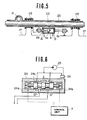
- the actuator 6 is arranged to actuate a front wheel steering linkage which may be of a type shown in Fig. 3 or a type shown in Fig. 4.
- the right and left front wheels 2 are connected to a vehicle body 17 through knuckle arms 13, side rods 14, a tie rod 15 and a link 16.
- a steering wheel 18 is connected to a steering gear 19.
- a swingable arm (pitman arm) 19a of the steering gear 19 is connected to the tie rod 15 through the actuator 6.
- the actuator 6 is a hydraulic servo actuator which provides the negative feedback input F to the front wheel steering linkage by expanding and contracting in accordance with the feedback signal of the control unit 7. Under command of the feedback signal, the actuator 7 alters the direction of the front wheels 2 in the negative direction which is opposite to the turn direction commanded by the driver through the steering wheel 18 or which is such a direction as to reduce or tend to reduce the yaw rate caused by the disturbance.
- the front wheels 2 are steered only by the steering input 0 supplied from the steering wheel 18.
- a turning motion is transmitted from the steering wheel 18 through the pitman arm 19a, the actuator 6 held in the deactivated state, the tie rod 15, the side rods 14 and the knuckle arms 13 to the front wheels 2.
- the actuator 6 is connected with a steering gear of a rack and pinion type.
- a rack 20 is connected between right and left side rods 14.
- the rack 20 is engaged with a pinion 21 which is rotated by the steering wheel 18.
- the rack 20 and the pinion 21 are enclosed in a gear housing 22.
- the pinion 21 is rotated, the rack 20 is moved longitudinally (toward the right or left front wheel 2), and the front wheels 2 are steered.
- the gear housing 22 is supported on the vehicle body 17 through rubber bushes 23.
- the actuator 6 is connected with the gear housing 22 so that the gear housing 22 can be moved relative to the vehicle body toward the right or left front wheel 2 by the actuator 6.
- the actuator 6 has a hydraulic cylinder having a piston 6a which divides a cylinder bore into two chambers one of which has a port A and the other of which has a port B.
- the cylinder actuator 6 is disposed between the gear housing 22 and the vehicle body 17.
- the piston 6a is connected to the gear housing 22 through a piston rod 6b, and the cylinder is connected to the vehicle body 17 through a rod 6c.
- the actuator 6 is controlled by an electromagnetic spool valve 24. As shown in Fig.
- the electromagnetic spool valve 24 has two solenoids 24a and 24b, and a spool 24c which is held in a neutral position shown in Fig. 6 by springs when both solenoids are deenergized.
- the valve 24 is connected with an oil pump 25 and a reservoir 26 by fluid conduits.
- the valve 24 has a port A' fluidly connected with the port A of the hydraulic cylinder actuator 6, and a port B' fluidly connected with the port B of the cylinder actuator 6.
- the control unit 7 energizes the solenoid 24a or the solenoid 24b selectively.
- the control unit 7 energizes the solenoid 24b, and thereby moves the spool 24c rightwards in Fig. 6 to supply an oil pressure to the port B'.
- This oil pressure is introduced into the cylinder actuator 6 through the port B, and moves the piston 6a in a direction shown by an arrow C in Fig. 5.
- This movement of the piston 6a forces the gear housing 22 to move together with the rack 20 in the same direction by deflecting the rubber bushes 23.
- the front wheels 2 are steered right, that is, in such a negative direction as to return the vehicle toward the straight ahead position or reduce the yaw rate of the vehicle produced during the absence of the driver's steering command.
- the control unit 7 energizes the solenoid 24a, and steers the front wheels 2 in the negative direction, which is a left direction in this case, to return the front wheels 2 toward the straight ahead position or reduce the yaw rate produced by the disturbance.
- a gain adjuster 60 controls the yaw rate gain by varying the first and second coefficients K 1 and K 2 in accordance with any one or more of conditions, such as vehicle speed, force of-side wind, weather condition, road condition, acceleration or deceleration of the vehicle, vehicle weight, weight distribution between front and rear axles, and driver's taste. It is preferable to decrease the yaw rate gain as the vehicle speed increases from the viewpoint of the directional control and stability of the vehicle at high speeds.
- the gain adjuster 60 decreases the yaw rate gain by increasing the first coefficient K 1 or decreasing the second coefficient K 2 or varying both of the first and second coefficients K 1 and K 2 so as to increase the feedback gain K 1 -K 2 , as the vehicle speed increases.
- the yaw rate gain should be decreased as the environment of the vehicle become worse for the directional control and stability of the vehicle. Therefore, if the environmental conditions are taken into account, the gain adjuster 60 decreases the yaw rate gain by increasing the feedback gain K l -K 2 when the side wind becomes stronger or when the weather becomes rainy or when the road surface becomes rugged. As the acceleration of the vehicle increases, the tendency to power-slide of the vehicle increase.
- the gain adjuster 60 may be arranged to decrease the yaw rate gain by increasing the feedback gain K i -K 2 as the acceleration or deceleration increases.
- the gain adjuster 60 may be arranged to decrease the yaw rate gain by increasing the feedback gain K 1 -K 2 as the vehicle weight increases.
- the gain adjuster 60 may be arranged to decrease the yaw rate gain by increasing the feedback gain K i -K 2 as the weight on the rear axle increases. Furthermore, the gain adjuster 60 may be arranged to vary either or both of the first and second coefficients K 1 and K 2 in accordance with driver's manual operation so that the control system can provide the yaw rate gain suitable to the driver's taste. Thus, the gain adjuster 60 controls the yaw rate gain in accordance with any one or more of the vehicle speed, side wind force, weather condition, road surface condition, rate of change of vehicle velocity with respect to time, vehicle weight, weight distribution between front and rear wheels, and driver's taste.
- a second embodiment of the present invention is shown in Fig. 7, in which the actual behavior of the vehicle is determined by the lateral acceleration a of the vehicle instead of the yaw rate ⁇ .
- the vehicle behavior sensor of this embodiment is a lateral G.sensor 3".
- the sensor 3" senses the lateral acceleration of the vehicle, and the first coefficient setter 8 provides the operational amplifier 9 with a signal indicative of the product of the sensed lateral acceleration a and a first coefficient K 1 . Since the actual behavior is determined by the lateral acceleration, the reference quantity of this embodiment is set equal to -
- the first and second coefficients K 1 and K 2 and the constant K are set at values adapted to the lateral acceleration instead of the yaw rate.
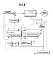
- Fig. 8 shows a third embodiment of the present invention in which the actual quantity indicative of the actual behavior of the vehicle is set as being equal to a linear combination of the yaw rate and the time derivative of the yaw rate in order to further improve the cornering characteristic of the vehicle.
- the production of the negative feedback input F is retarded with respect to the detection of the yaw rate or lateral acceleration because of lag of each consituent elements of the control system, and besides, signal damping in unavoidable in a high frequency range. Accordingly, in some cases, the first and second embodiments cannot improve the yaw rate gain characteristic and the phase lag characteristic to a desired extent as shown by curves b and b' in Fig.
- the third embodiment is arranged to eliminate lag and damping by adding a rate signal ⁇ which changes speedily in response to a change of the actual behavior of the vehicle.
- the yaw rate ⁇ sensed by the yaw rate sensor 3' is inputted directly to the operational amplifier 9 on one hand, and differentiated by a differentiator or differentiating circuit 61 on the other hand.
- a constant setter 62 receives the time derivative ⁇ from the differentiator 61, and inputs the product k 1 ⁇ of the time derivative of ⁇ and a predetermined constant k 1 to the operational amplifier 9.
- the operational amplifier 9 sets the actual quantity equal to the sum ⁇ + k 1 ⁇ .
- the control system of the third embodiment can provide the desired frequency characteristics as shown by the curves b and b' in Fig. 17.
- Fig. 9 shows a fourth embodiment of the present invention in which the yaw rate and the time derivative of the yaw rate are obtained in a different way from that of the third embodiment.
- a front lateral G sensor 52 is mounted on the vehicle 1 at the front
- a rear lateral G sensor 53 is mounted on the vehicle at the rear.
- the front and rear lateral G sensors 52 and 53 are at a distance l apart from each other along the longitudinal line of the vehicle 1.
- the front lateral G sensor 52 senses a lateral acceleration of the front of the vehicle
- the rear lateral G sensor 53 senses a lateral acceleration G 2 of the rear of the vehicle.
- the time derivative ⁇ of the yaw rate is equal to the quotient obtained by dividing the front lateral acceleration G 1 minus the rear lateral acceleration G 2 by the distance 1. Therefore, a differential amplifier 54 receives the front and rear lateral accelerations G 1 and G 2 sensed, respectively, by the front and rear sensors 52 and 53, and determines
- the output signal of the differential amplifier 54 indicative of is sent to an integrator or integrating circuit 63, and the constan setter 62.
- the integrator 63 determines the yaw rate ⁇ by finding the time integral of the input, and then inputs the thus-determined yaw rate ⁇ to the operational amplifier 9.
- the constant setter 62 multiplies the output of the differential amplifier 54 by a predetermined constant k 1 , and-provides the operational amplifier 9 with signal equal to k 1 ⁇ .
- the fourth embodiment can eliminate the necessity of a costly yaw rate gyro by employing the inexpensive lateral G sensors 52 and 53.
- a fifth embodiment of the present invention is not illustrated.
- the actual quantity indicative of the actual behavior of the vehicle is equal to a linear combination of the lateral acceleration a and the time derivative a of the lateral acceleration, while the reference quantity is equal to
- the control unit-of fifth embodiment has the lateral G sensor for sensing the lateral acceleration of the vehicle, and a differentiator for finding the time derivative of the lateral acceleration.
- the operational amplifier 9 of the fifth embodiment determines
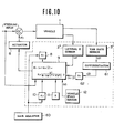
- FIG. 10 A sixth embodiment of the present invention is shown in Fig. 10.
- the lateral G sensor 3 the yaw rate sensor 3', and the differentiator 61 for finding the time derivative (yaw acceleration) ⁇ of the yaw rate sensed by the yaw rate sensor 3'.
- the operational amplifier 9 of this embodiment sets the actual quantity equal to a linear combination of the lateral acceleration a and the time derivative of the yaw rate, and produces the feedback signal indicative of
- the actual quantity is set equal to a linear combination of the yaw rate and the time derivative a of the lateral acceleration.
- the reference quantity is equal to
- control systems of the fourth, fifth, sixth and seventh embodiments can provide the desired frequency characteristics as in the third embodiment.
- a eighth embodiment of the present invention is shown in Fig. 11.
- the actual quantity is set equal to the linear combination of the lateral acceleration and the time derivative of the yaw rate as in the sixth embodiment of Fig. 10.
- the eighth embodiment uses only one lateral G sensor and requires neither a differentiator nor an integrator, so that the eighth embodiment is advantageous in cost.
- a front lateral G sensor 52 is mounted on the vehicle at the front.
- the front lateral G sensor 52 is at a distance l' apart from the center of gravity 1a of the vehicle 1 along the longitudinal line of the vehicle.
- the eighth embodiment utilizes the relationship that a front lateral acceleration G 1 sensed by the front lateral G sensor 52 is equal to a sum a + l'. ⁇ between the lateral acceleration a acting at the center of gravity 1a and a product of the time derivative ⁇ of the yaw rate and the distance l'.
- the front lateral G sensor 52 is located at such a position that the distance l' is equal to the constant k 1 . Therefore, the constant setter 62 is removed.
- the front lateral acceleration G 1 sensed by the sensor 52 is directly inputted to the operational amplifier 9, which produces the feedback signal indicative of
- a ninth embodiment of the present invention is shown in Fig. 12.
- the control units of the preceding embodiments are arranged to steer the front wheels 2 in the negative direction.
- the control unit 7 of the ninth embodiment is arranged to steer the rear wheels 27 in such a negative direction as to reduce the yaw rate of the vehicle. That is, if the front wheels 2 are steered by the steering wheel 18, the control unit 7 steers the rear wheels 27 in the same direction as the front wheels 2.
- the ninth embodiment uses any one of the control units 7 of the preceding embodiments as its control unit 7.
- the actuator 6 of the ninth embodiment inputs the negative feedback input F in the form of a steering angle -e of the rear wheels 27 into a rear wheel steering mechanism.
- Fig. 13 shows one example of the actuator 6 used in the ninth embodiment
- Figs. 14 to 16 shows another example.
- the front wheel steering mechanism comprises a steering wheel 18, a steering gear enclosed in a gear housing 22, side rods 14 and knuckle arms 13, but it is not provided with the actuator 6.
- the front wheel steering mechanims of this embodiment is a conventional one.
- each rear wheel 27 is rotatably supported by a knuckle arm 28.
- the right and left knuckle arms 28 are connected by a tie rod 29.
- the actuator 6 of this embodiment comprises a hydraulic cylinder actuator having a piston 6a.
- the piston 6a of the actuator 6 is fixed to the tie rod 29.
- a hydraulic system for the actuator 6 has an oil pump 31 driven by an engine 30 mounted on the vehicle.
- the oil pump 31 sucks oil from an oil reservoir 32 and discharges the oil to an unload valve 33.
- the unload valve 33 controls the pressure of the oil discharged from the oil pump at a predetermined value, and supplies the pressured oil to an accumulator 34.
- the oil is supplied from the accumulator 34 to a servo valve 36 through a supply conduit 35.
- a return conduit 37 conveys an unnecessary oil from the servo valve 36 to the reservoir 32.
- the servo valve 36 is controlled by the control unit 7 which is identical to any one of the control units of the preceding embodiments.
- the control unit 7 commands the servo valve 36 to supply the oil pressure to the right cylinder chamber of the hydraulic cylinder, as viewed in Fig. 13. Therefore, the rear wheels 27 are steered in the same direction as the front wheels are steered by the steering wheel 18, that is, the right direction in this example, or in such a direction as to reduce the yaw rate produced by the disturbance.
- the control unit 7 steers the rear wheels 27 in the same direction as the front wheels 2 are turned or in such a direction as to reduce the leftward yaw rate of the vehicle caused by the disturbance.
- each of the rear wheels 27 is rotatably supported by a wheel support member 38.
- the wheel support member 38 of each rear wheel 27 is supported on the vehicle body 17 by a radius rod 39 in the fore and aft direction of the vehicle, and by two parallel lateral rods 40 and 41 in the lateral direction of the vehicle.
- a strut assembly 42 extends upwardly from the wheel support member 38 to the vehicle body 17.
- the strut assembly 42 has a suspension spring 43.
- the actuator 6 of a hydraulic cylinder type is disposed in a middle portion of the lateral rod 40 of each rear wheel 27.
- the actuator 6 has a piston 6a, a piston rod 6b and two fluid chambers separated by the piston 6a.
- a fluid port A is formed in one fluid chamber and a fluid port B is formed in the other fluid chamber.
- the lateral rod 40 is divided into an outer portion 40a and an inner portion 40b.
- the actuator 6 is disposed between the inner and outer portions 40b and 40a.
- the piston rod 6a and the outer portion 40a of the lateral rod 40 are fixed end to end with the interposition of a circular disc 47 as to form an integral unit.
- the axes of the piston rod 6b and the outer portion 40a lie on the same straight line.
- the inner portion 40b of the lateral rod 40 is fixed to the cylinder so as to form an integral unit.
- Rubber bushes 45 and 46 are disposed on both sides of the disc 44, and enclosed in a tubular case 47 which is fixed to the cylinder so that the rubber bushes 45 and 46 are immovable axially.
- An outboard end of the outer portion 40a of the lateral rod 40 is connected to the wheel support member 38 through a rubber bush 49 and a pin 48 fixed to the support member 38 as an outboard end of the lateral rod 41.
- An inboard end of the inner portion 40b of the lateral rod 40 is connected to the vehicle body 17 through a rubber bush 51 and a pin 50 fixed to the vehicle body 17 as an inboard end of the lateral rod 41.
- the fluid ports A and B of the actuator 6 are fluidly connected, respectively, with ports A' and B' of an electromagnetic spool valve 24 similar to the spool valve of Fig. 6.
- the valve 24 is controlled by the control unit 7 identical to any one of the control units of the preceding embodiments.
- the control unit 7 energizes a solenoid 24b of the valve 24 and thereby moves a spool 24c rightwards in Fig. 14. Accordingly, the fluid pressure is supplied to the port B through the port B', and the piston rod 6b is forced to move toward the inboard end of the lateral rod 40 as shown by an arrow in Fig. 16. During this, the piston rod 6b deflects the rubber bush 46 elastically, and the outer portion 40a of the lateral rod 40 moves toward the inboard end together with the piston rod 6b.
- the left rear wheel 27 is turned from a position shown by a solid line in Fig. 14 to a position shown by a two-dot chain line.
- the right rear wheel 27 is steered in the same direction as the left rear wheel 27 by the actuator 6 for the right rear wheel.
- the rear wheels 27 are turned in the same direction as the front wheels are turned by the steering wheel 18 or in such a direction as to reduce the yaw rate produced by the disturbance.
- the control unit 7 energizes a solenoid 24a of the valve 24 and supplies the fluid pressure to the port A of the actuator 6. Therefore, the rear wheels 27 are turned in the same direction as the front wheels 2 are turned by the steering wheel 18 or in such a direction as to reduce the yaw rate caused by the disturbance.
Abstract
Description
- The present invention relates to an auxiliary steering system for automatically steering a wheeled vehicle so as to improve a cornering characteristic, and a directional stability of the vehicle, in addition to a main steering action commanded by a driver.
- A turning behavior and steering stability of a wheeled vehicle are usually described by a relationship between a steering input, and a yaw rate or a lateral acceleration of the vehicle. The steering input is a driver's command to steer the vehicle. In general, a steering angle 0 of a steering wheel is regarded as the steering input. The yaw rate (or yaw angular velocity) is an angular velocity of a rotation of the vehicle about a vertical axis passing through the center of gravity of the vehicle. The lateral acceleration is an acceleration of the center of gravity of the vehicle in a lateral direction of the vehicle.
- It is desired that a vehicle should be turned to an amount corresponding to the driver's steering input without being affected by a disturbance such as a side wind and a friction coefficient of a road surface, and without delay. The amount of a turn of a vehicle can be described in terms of a ratio (yaw rate gain) of the yaw rate $ (or the lateral acceleration a) to the steering input (the steering angle e of the steering wheel). The delay can be described by a lag (phase lag) of an output of the yaw rate (or the lateral acceleration) with respect to the steering input.
- In a vehicle having no auxiliary steering control, the yaw rate gain is enhanced at a certain steering frequency, as shown by a curve "a" in Fig. 17, so that the behavior of the vehicle responsive to the steering input is increased abruptly at or near this steering frequency. Furthermore, the phase lag increases rapidly as the steering frequency increases as shown by a curve "a'" in Fig. 17. Therefore, the behavior of the vehicle is retarded with respect to the steering input, so that much skill is required for controlling the vehicle. It is desired that both of the yaw rate gain and the phase lag remain constant over the full range of the steering frequency.
- Therefore, there has been proposed an auxiliary steering control system, as shown in Fig. 1, which steers the front or rear wheels in proportion to the yaw rate or lateral acceleration of the vehicle in such a negative direction as to reduce the direction change of the vehicle while the front wheels are steered by the steering input in a conventional manner. However, the auxiliary steering control system of this type is still unsatisfactory in that this system cannot fully eliminate the influence of the disturbance without decreasing the yaw rate gain excessively.
- It is an object of the present invention to provide an auxiliary steering control system in which a hundred percent of the feedback is obtained to fully eliminate the influence of the disturbance when the steering input is equal to zero, and a desired percent of the feedback is obtained to provide a desired yaw rate gain when the steering wheel is turned.
- According to the present invention, a vehicle comprises road wheels, a steering wheel, a steering mechanism for steering the vehicle by altering the direction of at least one of the road wheels in accordance with an angular displacement of the steering wheel. The vehicle further comprises a negative feedback system which comprises a steering angle sensor, vehicle behavior sensing means, negative feedback means, and actuating means. The steering angle sensor senses the angular displacement of the steering wheel. The vehicle behavoir sensing means senses at least one variable which is indicative of an actual turning behavoir of the vehicle. The vehicle behavoir sensing means may sense either or both of a yaw rate of the vehicle and a lateral acceleration of the center of gravity of the vehicle. The negative feedback means is connected with the steering angle sensor and the vehicle behavoir sensing means, for producing a negative feedback signal in accordance with a difference between an actual quantity determined in accordance with the variable sensed by the vehicle behavior sensing means and a reference quantity determined in accordance with the angular displacement sensed by the steering angle sensor. The actuating means steers the vehicle by altering the direction of at least one of the road wheels in accordance with the negative feedback signal in such a direction as to reduce the variable.
- The variable to be sensed by the vehicle behavoir sensing means may be a yaw rate of the vehicle or a lateral acceleration of the center of gravity of the vehicle. Preferably, the vehicle further comprises a vehicle speed sensor for sensing the speed of the vehicle, and the feedback means determines the reference quantity in accordance with the angular displacement sensed by the steering angle sensor and the vehicle speed sensed by the vehicle speed sensor. The actual quantity may be the yaw rate or the lateral acceleration, or a linear combination of the yaw rate and the time derivative of the yaw rate or the lateral acceleration, or a linear combination of the lateral acceleration and the time derivative of the lateral acceleration or the yaw rate. The reference quantity may be a function of the angular displacement of the steering wheel and the vehicle speed, whose value is approximately equal to the actual yaw rate or lateral acceleration if there is no disturbance.
-
- Fig. 1 is a schematic view of a negative feedback system of a conventional type auxiliary steering control system;
- Fig.,2 is a schematic view of a negative feedback system of a first embodiment according to the present invention;
- Fig. 3 is a schematic plan view of one example of a front wheel steering system which can be used in the present invention when the negative feedback steering control is performed by the front wheels;
- Fig. 4 is a schematic plan view of another example of a front wheel steering system which can be used in the present invention when the negative feedback steering control is performed by the front wheels;
- Fig. 5 is a detailed sectional view of a steering gear and an actuator of Fig. 4;
- Fig. 6 is a detailed sectional view of an electromagnetic spool valve used in the example of Fig. 4;
- Figs. 7 to 11 are schematic views of negative feedback systems of five other embodiments of the present invention, respectively;
- Fig. 12 is a schematic view of a negative feedback system of still another embodiment of the present invention in which the negative feedback steering control is performed by the rear wheels;
- Fig. 13 is a schematic plan view of one example of a rear wheel steering system used in the embodiment of Fig. 12;
- Fig. 14 is a schematic plan view of another example of a rear wheel steering system used in the embodiment of Fig. 12;
- Fig. 15 is a schematic elevation as viewed from a line XV-XV in Fig. 14 in a direction shown by arrows;
- Fig. 16 is a detailed sectional view of an actuator shown in Fig. 14; and
- Fig. 17 is a diagram showing frequency characteristics of auxiliary steering control systems.
- Fig. 1 shows the above-mentioned auxiliary steering control system of a conventional type. In this system,
front wheels 2 of avehicle 1 are steered directly by the steering input on one hand. Thefront wheels 2 are steered, on the other hand, through a negative feedback circuit comprising avehicle behavior sensor 3, acoefficient setter 4, anamplifier 5 and anactuator 6. Thevehicle behavior sensor 3 senses the yaw rate $ or lateral acceleration a of the vehicle, which is sent to theactuator 6 through thecoefficient setter 4 and theamplifier 5. Theactuator 6 provides a negative feedback input F to a front wheel steering mechanism of the vehicle. The aim of this auxiliary steering control system is to change the yaw rate gain versus steering frequency characteristic from the curve "a" of Fig. 17 toward a flatter curve "b" of a one-dot chain line, and to decrease the phase lag toward a curve "b'" of a one-dot chain line. - Even if the steering input is zero, this auxiliary steering control system steers the front wheels in the negative direction to reduce the yaw rate if there is any yaw rate or lateral acceleration caused by a disturbance such as a side wind. In this system, however, the negative feedback input F is determined only by a product of a predetermined coefficient K' and the yaw rate or lateral acceleration. Therefore, if the coefficient K' is great enough to fully eliminate the,adverse influence of the disturbance, the yaw rate gain becomes so small that the driver experiences difficulty to steer the vehicle. In view of this, the coefficient K' is usually set within a range from 0.1 to 0.4. Consequently, this sytem cannot fully eliminate the influence of the disturbance, but this system can correct the vehicle bahavior only to about one third of the full extent (when K' is equal to 0.3).
- One embodiment of the present invention is shown in Fig. 2. A
vehicle 1 is steered by means offront wheels 2 in accordance with a steering input corresponding to a driver's steering command. For example, the steering input is asteering angle 0 which is an angular displacement of a steering wheel of thevehicle 1. Supplementarily, a negativefeedback control unit 7 steers thevehicle 1 in a negative feedback manner by using anactuator 6. Thecontrol unit 7 determines an actual quantity indicative of an actual turning behavior of the vehicle from a predetermined controlled variable such as a yaw rate (yaw angular velocity) of the vehicle, and produce a feedback signal in accordance with a difference between the determined actual quantity and a predetermined reference quantity indicative of a desired reference turning behavior of the vehicle. Thecontrol unit 7 has a vehicle behavior sensor for sensing the controlled variable. In this embodiment, the variable is the yaw rate ϕ (ϕ)of the vehicle, and the vehicle behavior sensor is a yaw rate sensor 3' such as a yaw rate gyro. The yaw rate sensor 3' senses the yaw rate φ of the vehicle, and sends a signal indicative of the sensed yaw rate to afirst coefficient setter 8. Thefirst coefficient setter 8 determines a product K1φ of a preset first coefficient K1 and the sensed yaw rate φ, and sends a signal indicative of the determined product to anoperational amplifier 9. In this embodiment, the first coefficient K1 is equal to 1.0,for example.. - The
operational amplifier 9 of thecontrol unit 7 further receives the steering input (the steering angle θ of the steering wheel), a second coefficient K2 determined by asecond coefficient setter 10, a constant K (stability factor) determined by aconstant setter 11, and a vehicle speed V sensed by avehicle speed sensor 12. In this embodiment, the second coefficient K2 is equal to 0.7, for example. From these input data, and additional data of a steering gear ratio N and a wheel base ℓW which are both inherent to the vehicle, theoperational amplifier 9 determines
operational amplifier 9 amplifies a signal indicative of the result
actuator 6. - In this embodiment, the actual quantity indicative of the actual turning behavior of the
vehicle 1 is the yaw rate sensed by the yaw rate sensor 3', and the reference quantity is
- When the steering wheel is not turned, the reference quantity

operational amplifier 9 is equal to zero because thesteering input 6 is equal to zero. If there is no disturbance such as a side wind, and the yaw rate ϕ is equal to zero, then the quantity K1φ is also zero. Therefore, theoperational amplifier 9 sends no signal to theactuator 6, and theactuator 6 produces no feedback input F. In this state, thecontrol unit 7 can prevent.the front wheels from being steered uselessly. - If a disturbance arises and causes the yaw rate during the absence of the steering input, then the quantity K1φ deviates from zero while the reference quantity

actuator 6, which therefore steers thefront wheels 2 with the negative feedback input F so as to eliminate the yaw rate caused by the disturbance completely whereas the steering input remains zero. - When the steering wheel is turned, the
control unit 7 supplies theactuator 6 with the signal indicative of the difference obtained by the subtraction whose minuend is the product of the first coefficient K1 and the sensed yaw rate φ and whose subtrahend is the product of the second coefficient K2 and the reference quantity
front wheels 2 secondarily in a return or negative direction opposite to a turn or positive direction commanded by the steering input. In this case, the feedback gain is determined by the difference obtained by subtracting the second coefficient K2 from the first coefficient K1. In this embodiment, the feedback gain is normally set equal to 0.3 by setting the first coefficient K1 equal to 1.0 and the second coefficient K2 equal to 0.7, so that the desired steering characteristic can be obtained. - Whether the reference quantity is exactly or approximately equal to


control unit 7 can estimate the disturbance such as a side wind more accurately by comparing the actual quantity and the reference quantity. - In this embodiment, the
actuator 6 is arranged to actuate a front wheel steering linkage which may be of a type shown in Fig. 3 or a type shown in Fig. 4. - In Fig. 3, the right and left
front wheels 2 are connected to avehicle body 17 throughknuckle arms 13,side rods 14, atie rod 15 and alink 16. Asteering wheel 18 is connected to asteering gear 19. A swingable arm (pitman arm) 19a of thesteering gear 19 is connected to thetie rod 15 through theactuator 6. Theactuator 6 is a hydraulic servo actuator which provides the negative feedback input F to the front wheel steering linkage by expanding and contracting in accordance with the feedback signal of thecontrol unit 7. Under command of the feedback signal, theactuator 7 alters the direction of thefront wheels 2 in the negative direction which is opposite to the turn direction commanded by the driver through thesteering wheel 18 or which is such a direction as to reduce or tend to reduce the yaw rate caused by the disturbance. While there is no feedback steering control action of theactuator 7, thefront wheels 2 are steered only by thesteering input 0 supplied from thesteering wheel 18. In this case, a turning motion is transmitted from thesteering wheel 18 through the pitman arm 19a, theactuator 6 held in the deactivated state, thetie rod 15, theside rods 14 and theknuckle arms 13 to thefront wheels 2. - In the case of Figs. 4 to 6, the
actuator 6 is connected with a steering gear of a rack and pinion type. Arack 20 is connected between right andleft side rods 14. Therack 20 is engaged with apinion 21 which is rotated by thesteering wheel 18. Therack 20 and thepinion 21 are enclosed in agear housing 22. In accordance with thesteering input 6 provided by thesteering wheel 18, thepinion 21 is rotated, therack 20 is moved longitudinally (toward the right or left front wheel 2), and thefront wheels 2 are steered. - The
gear housing 22 is supported on thevehicle body 17 throughrubber bushes 23. Theactuator 6 is connected with thegear housing 22 so that thegear housing 22 can be moved relative to the vehicle body toward the right or leftfront wheel 2 by theactuator 6. Theactuator 6 has a hydraulic cylinder having apiston 6a which divides a cylinder bore into two chambers one of which has a port A and the other of which has a port B. Thecylinder actuator 6 is disposed between thegear housing 22 and thevehicle body 17. Thepiston 6a is connected to thegear housing 22 through apiston rod 6b, and the cylinder is connected to thevehicle body 17 through arod 6c. Theactuator 6 is controlled by anelectromagnetic spool valve 24. As shown in Fig. 6, theelectromagnetic spool valve 24 has twosolenoids 24a and 24b, and aspool 24c which is held in a neutral position shown in Fig. 6 by springs when both solenoids are deenergized. Thevalve 24 is connected with anoil pump 25 and areservoir 26 by fluid conduits. Thevalve 24 has a port A' fluidly connected with the port A of thehydraulic cylinder actuator 6, and a port B' fluidly connected with the port B of thecylinder actuator 6. - The
control unit 7 energizes the solenoid 24a or thesolenoid 24b selectively. When thefront wheels 2 are turned by the driver in such a left turn direction as to turn the vehicle left or when the yaw rate of the same left turn direction arises during the absence of the steering input of thesteering wheel 18, thecontrol unit 7 energizes thesolenoid 24b, and thereby moves thespool 24c rightwards in Fig. 6 to supply an oil pressure to the port B'. This oil pressure is introduced into thecylinder actuator 6 through the port B, and moves thepiston 6a in a direction shown by an arrow C in Fig. 5. This movement of thepiston 6a forces thegear housing 22 to move together with therack 20 in the same direction by deflecting therubber bushes 23. Therefore, thefront wheels 2 are steered right, that is, in such a negative direction as to return the vehicle toward the straight ahead position or reduce the yaw rate of the vehicle produced during the absence of the driver's steering command. When thefront wheels 2 are turned in a right turn direction by thesteering wheel 18 or when the yaw rate of the right turn direction arises because of a disturbance, thecontrol unit 7 energizes the solenoid 24a, and steers thefront wheels 2 in the negative direction, which is a left direction in this case, to return thefront wheels 2 toward the straight ahead position or reduce the yaw rate produced by the disturbance. - In the embodiment of Fig. 2, there is further provided a
gain adjuster 60. Thegain adjuster 60 controls the yaw rate gain by varying the first and second coefficients K1 and K2 in accordance with any one or more of conditions, such as vehicle speed, force of-side wind, weather condition, road condition, acceleration or deceleration of the vehicle, vehicle weight, weight distribution between front and rear axles, and driver's taste. It is preferable to decrease the yaw rate gain as the vehicle speed increases from the viewpoint of the directional control and stability of the vehicle at high speeds. Therefore, if thegain adjuster 60 employs the vehicle speed, thegain adjuster 60 decreases the yaw rate gain by increasing the first coefficient K1 or decreasing the second coefficient K2 or varying both of the first and second coefficients K1 and K2 so as to increase the feedback gain K1-K2, as the vehicle speed increases. Similarly, the yaw rate gain should be decreased as the environment of the vehicle become worse for the directional control and stability of the vehicle. Therefore, if the environmental conditions are taken into account, thegain adjuster 60 decreases the yaw rate gain by increasing the feedback gain Kl-K2 when the side wind becomes stronger or when the weather becomes rainy or when the road surface becomes rugged. As the acceleration of the vehicle increases, the tendency to power-slide of the vehicle increase. As the deceleration of the vehicle increases, the tendency to tack-in increases. Therefore, thegain adjuster 60 may be arranged to decrease the yaw rate gain by increasing the feedback gain Ki-K2 as the acceleration or deceleration increases. As the weight of the vehicle increases, the lateral grip of the tires in the sidewise direction becomes deficient relatively, so that the stability in steering the vehicle becomes worse. Therefore, thegain adjuster 60 may be arranged to decrease the yaw rate gain by increasing the feedback gain K1-K2 as the vehicle weight increases. As the weight on the rear wheels increases as compared with the weight on the front wheels, the centrifugal force produced on a turn of the vehicle tends to cause the rear end of the vehicle to slide outwardly. Therefore, thegain adjuster 60 may be arranged to decrease the yaw rate gain by increasing the feedback gain Ki-K2 as the weight on the rear axle increases. Furthermore, thegain adjuster 60 may be arranged to vary either or both of the first and second coefficients K1 and K2 in accordance with driver's manual operation so that the control system can provide the yaw rate gain suitable to the driver's taste. Thus, thegain adjuster 60 controls the yaw rate gain in accordance with any one or more of the vehicle speed, side wind force, weather condition, road surface condition, rate of change of vehicle velocity with respect to time, vehicle weight, weight distribution between front and rear wheels, and driver's taste. - A second embodiment of the present invention is shown in Fig. 7, in which the actual behavior of the vehicle is determined by the lateral acceleration a of the vehicle instead of the yaw rate ϕ. The vehicle behavior sensor of this embodiment is a
lateral G.sensor 3". Thesensor 3" senses the lateral acceleration of the vehicle, and thefirst coefficient setter 8 provides theoperational amplifier 9 with a signal indicative of the product of the sensed lateral acceleration a and a first coefficient K1. Since the actual behavior is determined by the lateral acceleration, the reference quantity of this embodiment is set equal to -
- The first and second coefficients K1 and K2 and the constant K are set at values adapted to the lateral acceleration instead of the yaw rate.
- Fig. 8 shows a third embodiment of the present invention in which the actual quantity indicative of the actual behavior of the vehicle is set as being equal to a linear combination of the yaw rate and the time derivative of the yaw rate in order to further improve the cornering characteristic of the vehicle. In the first and second embodiments having no derivative control action, the production of the negative feedback input F is retarded with respect to the detection of the yaw rate or lateral acceleration because of lag of each consituent elements of the control system, and besides, signal damping in unavoidable in a high frequency range. Accordingly, in some cases, the first and second embodiments cannot improve the yaw rate gain characteristic and the phase lag characteristic to a desired extent as shown by curves b and b' in Fig. 17, but only to an insufficient extent as shown by curves c and c' in Fig. 17. The third embodiment is arranged to eliminate lag and damping by adding a rate signal φ which changes speedily in response to a change of the actual behavior of the vehicle. In the system of Fig. 8, the yaw rate ϕ sensed by the yaw rate sensor 3' is inputted directly to the
operational amplifier 9 on one hand, and differentiated by a differentiator or differentiatingcircuit 61 on the other hand. Aconstant setter 62 receives the time derivative φ from thedifferentiator 61, and inputs the product k1φ of the time derivative of ϕ and a predetermined constant k1 to theoperational amplifier 9. Theoperational amplifier 9 sets the actual quantity equal to the sum φ + k1φ. Thus, the control system of the third embodiment can provide the desired frequency characteristics as shown by the curves b and b' in Fig. 17. - Fig. 9 shows a fourth embodiment of the present invention in which the yaw rate and the time derivative of the yaw rate are obtained in a different way from that of the third embodiment. In the fourth embodiment, a front
lateral G sensor 52 is mounted on thevehicle 1 at the front, and a rearlateral G sensor 53 is mounted on the vehicle at the rear. - The front and rear
lateral G sensors vehicle 1. The frontlateral G sensor 52 senses a lateral acceleration of the front of the vehicle, and the rearlateral G sensor 53 senses a lateral acceleration G2 of the rear of the vehicle. The time derivative φ of the yaw rate is equal to the quotient obtained by dividing the front lateral acceleration G1 minus the rear lateral acceleration G2 by thedistance 1. Therefore, adifferential amplifier 54 receives the front and rear lateral accelerations G1 and G2 sensed, respectively, by the front andrear sensors 
- The output signal of the
differential amplifier 54, indicative of
circuit 63, and theconstan setter 62. Theintegrator 63 determines the yaw rate φ by finding the time integral
operational amplifier 9. Theconstant setter 62 multiplies the output of thedifferential amplifier 54 by a predetermined constant k1, and-provides theoperational amplifier 9 with signal equal to k1φ. The fourth embodiment can eliminate the necessity of a costly yaw rate gyro by employing the inexpensivelateral G sensors - A fifth embodiment of the present invention is not illustrated. In the fifth embodiment, the actual quantity indicative of the actual behavior of the vehicle is equal to a linear combination of the lateral acceleration a and the time derivative a of the lateral acceleration, while the reference quantity is equal to

operational amplifier 9 of the fifth embodiment determines
- A sixth embodiment of the present invention is shown in Fig. 10. In the sixth embodiment, there are provided the
lateral G sensor 3", the yaw rate sensor 3', and thedifferentiator 61 for finding the time derivative (yaw acceleration) φ of the yaw rate sensed by the yaw rate sensor 3'. Theoperational amplifier 9 of this embodiment sets the actual quantity equal to a linear combination of the lateral acceleration a and the time derivative of the yaw rate, and produces the feedback signal indicative of
- In a seventh embodiment of the present invention which is not illustrated, the actual quantity is set equal to a linear combination of the yaw rate and the time derivative a of the lateral acceleration. The reference quantity is equal to

- The control systems of the fourth, fifth, sixth and seventh embodiments can provide the desired frequency characteristics as in the third embodiment.
- A eighth embodiment of the present invention is shown in Fig. 11. In the eighth embodiment, the actual quantity is set equal to the linear combination of the lateral acceleration and the time derivative of the yaw rate as in the sixth embodiment of Fig. 10. However, the eighth embodiment uses only one lateral G sensor and requires neither a differentiator nor an integrator, so that the eighth embodiment is advantageous in cost. As shown in Fig. 11, a front
lateral G sensor 52 is mounted on the vehicle at the front. The frontlateral G sensor 52 is at a distance ℓ' apart from the center of gravity 1a of thevehicle 1 along the longitudinal line of the vehicle. The eighth embodiment utilizes the relationship that a front lateral acceleration G1 sensed by the frontlateral G sensor 52 is equal to a sum a + ℓ'.φ between the lateral acceleration a acting at the center of gravity 1a and a product of the time derivative φ of the yaw rate and the distance ℓ'. In this embodiment, the frontlateral G sensor 52 is located at such a position that the distance ℓ' is equal to the constant k1. Therefore, theconstant setter 62 is removed. The front lateral acceleration G1 sensed by thesensor 52 is directly inputted to theoperational amplifier 9, which produces the feedback signal indicative of -

front wheels 2 in the negative direction. Thecontrol unit 7 of the ninth embodiment is arranged to steer therear wheels 27 in such a negative direction as to reduce the yaw rate of the vehicle. That is, if thefront wheels 2 are steered by thesteering wheel 18, thecontrol unit 7 steers therear wheels 27 in the same direction as thefront wheels 2. The ninth embodiment uses any one of thecontrol units 7 of the preceding embodiments as itscontrol unit 7. Theactuator 6 of the ninth embodiment inputs the negative feedback input F in the form of a steering angle -e of therear wheels 27 into a rear wheel steering mechanism. - Fig. 13 shows one example of the
actuator 6 used in the ninth embodiment, and Figs. 14 to 16 shows another example. In Fig. 13, the front wheel steering mechanism comprises asteering wheel 18, a steering gear enclosed in agear housing 22,side rods 14 and knucklearms 13, but it is not provided with theactuator 6. The front wheel steering mechanims of this embodiment is a conventional one. As shown in Fig. 13, eachrear wheel 27 is rotatably supported by aknuckle arm 28. The right and leftknuckle arms 28 are connected by atie rod 29. Thus, therear wheels 27 are steerable. Theactuator 6 of this embodiment comprises a hydraulic cylinder actuator having apiston 6a. Thepiston 6a of theactuator 6 is fixed to thetie rod 29. - A hydraulic system for the
actuator 6 has anoil pump 31 driven by anengine 30 mounted on the vehicle. Theoil pump 31 sucks oil from anoil reservoir 32 and discharges the oil to an unloadvalve 33. The unloadvalve 33 controls the pressure of the oil discharged from the oil pump at a predetermined value, and supplies the pressured oil to anaccumulator 34. The oil is supplied from theaccumulator 34 to aservo valve 36 through asupply conduit 35. Areturn conduit 37 conveys an unnecessary oil from theservo valve 36 to thereservoir 32. - The
servo valve 36 is controlled by thecontrol unit 7 which is identical to any one of the control units of the preceding embodiments. When thefront wheels 2 are steered right by turning thesteering wheel 18 right, or when the yaw rate of the vehicle in the right turn direction is produced by a disturbance in the absence of the steering input, thecontrol unit 7 commands theservo valve 36 to supply the oil pressure to the right cylinder chamber of the hydraulic cylinder, as viewed in Fig. 13. Therefore, therear wheels 27 are steered in the same direction as the front wheels are steered by thesteering wheel 18, that is, the right direction in this example, or in such a direction as to reduce the yaw rate produced by the disturbance. When thefront wheels 2 are steered left by turning thesteering wheel 18 left or when the leftward yaw rate is produced by a disturbance in the absence of a driver's steering command, thecontrol unit 7 steers therear wheels 27 in the same direction as thefront wheels 2 are turned or in such a direction as to reduce the leftward yaw rate of the vehicle caused by the disturbance. - In another example shown in Figs. 14 to 16, each of the
rear wheels 27 is rotatably supported by awheel support member 38. Thewheel support member 38 of eachrear wheel 27 is supported on thevehicle body 17 by aradius rod 39 in the fore and aft direction of the vehicle, and by two parallellateral rods strut assembly 42 extends upwardly from thewheel support member 38 to thevehicle body 17. Thestrut assembly 42 has asuspension spring 43. - The
actuator 6 of a hydraulic cylinder type is disposed in a middle portion of thelateral rod 40 of eachrear wheel 27. As shown in Fig. 16, theactuator 6 has apiston 6a, apiston rod 6b and two fluid chambers separated by thepiston 6a. A fluid port A is formed in one fluid chamber and a fluid port B is formed in the other fluid chamber. Thelateral rod 40 is divided into anouter portion 40a and aninner portion 40b. Theactuator 6 is disposed between the inner andouter portions piston rod 6a and theouter portion 40a of thelateral rod 40 are fixed end to end with the interposition of acircular disc 47 as to form an integral unit. The axes of thepiston rod 6b and theouter portion 40a lie on the same straight line. Theinner portion 40b of thelateral rod 40 is fixed to the cylinder so as to form an integral unit. Rubber bushes 45 and 46 are disposed on both sides of the disc 44, and enclosed in atubular case 47 which is fixed to the cylinder so that the rubber bushes 45 and 46 are immovable axially. - An outboard end of the
outer portion 40a of thelateral rod 40 is connected to thewheel support member 38 through arubber bush 49 and apin 48 fixed to thesupport member 38 as an outboard end of thelateral rod 41. An inboard end of theinner portion 40b of thelateral rod 40 is connected to thevehicle body 17 through arubber bush 51 and apin 50 fixed to thevehicle body 17 as an inboard end of thelateral rod 41. - The fluid ports A and B of the
actuator 6 are fluidly connected, respectively, with ports A' and B' of anelectromagnetic spool valve 24 similar to the spool valve of Fig. 6. Thevalve 24 is controlled by thecontrol unit 7 identical to any one of the control units of the preceding embodiments. - When the
front wheels 2 are turned right by thesteering wheel 18 or when the yaw rate in the same right direction is caused by a disturbance during the absence of the steering wheel movement, thecontrol unit 7 energizes asolenoid 24b of thevalve 24 and thereby moves aspool 24c rightwards in Fig. 14. Accordingly, the fluid pressure is supplied to the port B through the port B', and thepiston rod 6b is forced to move toward the inboard end of thelateral rod 40 as shown by an arrow in Fig. 16. During this, thepiston rod 6b deflects the rubber bush 46 elastically, and theouter portion 40a of thelateral rod 40 moves toward the inboard end together with thepiston rod 6b. As a result, the leftrear wheel 27 is turned from a position shown by a solid line in Fig. 14 to a position shown by a two-dot chain line. The rightrear wheel 27 is steered in the same direction as the leftrear wheel 27 by theactuator 6 for the right rear wheel. Thus, therear wheels 27 are turned in the same direction as the front wheels are turned by thesteering wheel 18 or in such a direction as to reduce the yaw rate produced by the disturbance. When the front wheels are turned left by thesteering wheel 18 or when the yaw rate in the left turn direction is produced by a disturbance during the absence of the steering wheel movement, thecontrol unit 7 energizes a solenoid 24a of thevalve 24 and supplies the fluid pressure to the port A of theactuator 6. Therefore, therear wheels 27 are turned in the same direction as thefront wheels 2 are turned by thesteering wheel 18 or in such a direction as to reduce the yaw rate caused by the disturbance.
Claims (33)


Applications Claiming Priority (2)
| Application Number | Priority Date | Filing Date | Title |
|---|---|---|---|
| JP15332/84 | 1984-01-31 | ||
| JP59015332A JPS60161256A (en) | 1984-01-31 | 1984-01-31 | Auxiliary steering for car |
Publications (3)
| Publication Number | Publication Date |
|---|---|
| EP0150856A2 true EP0150856A2 (en) | 1985-08-07 |
| EP0150856A3 EP0150856A3 (en) | 1986-02-12 |
| EP0150856B1 EP0150856B1 (en) | 1989-01-11 |
Family
ID=11885826
Family Applications (1)
| Application Number | Title | Priority Date | Filing Date |
|---|---|---|---|
| EP85101021A Expired EP0150856B1 (en) | 1984-01-31 | 1985-01-31 | Auxiliary steering system for wheeled vehicle |
Country Status (4)
| Country | Link |
|---|---|
| US (1) | US4878557A (en) |
| EP (1) | EP0150856B1 (en) |
| JP (1) | JPS60161256A (en) |
| DE (1) | DE3567420D1 (en) |
Cited By (23)
| Publication number | Priority date | Publication date | Assignee | Title |
|---|---|---|---|---|
| DE3642049A1 (en) * | 1985-12-09 | 1987-06-11 | Nissan Motor | CONTROL SYSTEM FOR VEHICLE STEERING WITH PARAMETER DETECTION |
| EP0282041A2 (en) * | 1987-03-09 | 1988-09-14 | Honda Giken Kogyo Kabushiki Kaisha | A yaw motion control device for a vehicle |
| EP0308263A2 (en) * | 1987-09-16 | 1989-03-22 | Honda Giken Kogyo Kabushiki Kaisha | Front and rear wheel steering vehicle with a minimized manoeuvering area |
| EP0309293A2 (en) * | 1987-09-25 | 1989-03-29 | Honda Giken Kogyo Kabushiki Kaisha | Method for controlling the front wheel steer angle |
| GB2215686A (en) * | 1988-02-13 | 1989-09-27 | Daimler Benz Ag | Supplementary steering system |
| US4878557A (en) * | 1984-01-31 | 1989-11-07 | Nissan Motor Co., Ltd. | Auxiliary steering system for wheeled vehicle |
| FR2636288A1 (en) * | 1988-09-13 | 1990-03-16 | Aisin Seiki | DEVICE AND METHOD FOR MAINTAINING THE STABILITY OF A VEHICLE |
| FR2641754A1 (en) * | 1989-01-19 | 1990-07-20 | Peugeot | STEERING DEVICE OF AT LEAST ONE VEHICLE WHEEL TRAIN |
| WO1990014980A1 (en) * | 1989-06-08 | 1990-12-13 | Group Lotus Plc | A wheeled vehicle steering system |
| FR2657821A1 (en) * | 1990-02-06 | 1991-08-09 | Aisin Seiki | |
| FR2657834A1 (en) * | 1990-02-06 | 1991-08-09 | Aisin Seiki | DEVICE FOR CONTROLLING THE DIRECTION OF A VEHICLE. |
| EP0460581A2 (en) * | 1990-06-04 | 1991-12-11 | Nippondenso Co., Ltd. | Signal processing circuit for yaw-rate sensor |
| DE4030846A1 (en) * | 1990-09-29 | 1992-04-02 | Bosch Gmbh Robert | METHOD FOR CONTROLLING THE STEERING ANGLE |
| EP0510365A2 (en) * | 1991-03-22 | 1992-10-28 | Mazda Motor Corporation | Rear wheel steering system for vehicle |
| US5168952A (en) * | 1987-06-11 | 1992-12-08 | Honda Giken Kogyo Kabushiki Kaisha | Driving wheel slip control system for vehicles |
| GB2258198A (en) * | 1991-07-13 | 1993-02-03 | Daimler Benz Ag | Method of producing a signal relating to instability of a vehicle based on its yaw behaviour. |
| EP0556659A1 (en) * | 1992-02-05 | 1993-08-25 | Toyota Jidosha Kabushiki Kaisha | Electric control apparatus for four-wheel steering system |
| US5261503A (en) * | 1990-07-11 | 1993-11-16 | Aisin Seiki Kabushiki Kaisha | Adaptive steering control system |
| US5373911A (en) * | 1991-12-18 | 1994-12-20 | Aisin Seiki Kabushiki Kaisha | Vehicle guidance control system |
| EP0694464A1 (en) * | 1994-07-28 | 1996-01-31 | Toyota Jidosha Kabushiki Kaisha | Device for controlling turn behaviour of vehicle |
| DE3826982C2 (en) * | 1987-08-10 | 2000-11-30 | Denso Corp | Auxiliary steering system connected to an anti-lock control system for use in motor vehicles |
| DE4401333C2 (en) * | 1993-01-19 | 2002-08-01 | Toyota Motor Co Ltd | The vehicle steering control system |
| DE4000995B4 (en) * | 1989-01-26 | 2008-02-28 | Volkswagen Ag | Steering system for motor vehicles |
Families Citing this family (59)
| Publication number | Priority date | Publication date | Assignee | Title |
|---|---|---|---|---|
| JPS60193775A (en) * | 1984-03-15 | 1985-10-02 | Honda Motor Co Ltd | Rear-wheels steering apparatus for car |
| JPS60193773A (en) * | 1984-03-15 | 1985-10-02 | Honda Motor Co Ltd | Front and rear wheels steering apparatus for car |
| JPS6246771A (en) * | 1985-08-24 | 1987-02-28 | Mazda Motor Corp | Steering device for car |
| JPH0615340B2 (en) * | 1985-12-27 | 1994-03-02 | 日産自動車株式会社 | Steering reaction force control device |
| JP2541928B2 (en) * | 1986-03-24 | 1996-10-09 | 日産自動車株式会社 | Vehicle attitude control device |
| JPH0733924Y2 (en) * | 1986-05-12 | 1995-08-02 | 三菱自動車工業株式会社 | Vehicle suspension system |
| JP2539818B2 (en) * | 1987-03-31 | 1996-10-02 | 豊田工機株式会社 | Steering force control device for power steering device |
| JP2740176B2 (en) * | 1987-12-28 | 1998-04-15 | 日産自動車株式会社 | Vehicle rear wheel steering method |
| JPH0829670B2 (en) * | 1988-02-18 | 1996-03-27 | 日産自動車株式会社 | Front and rear wheel drive force distribution control vehicle auxiliary steering method |
| US4996657A (en) * | 1988-03-18 | 1991-02-26 | Honda Giken Kogyo K.K. | Steering angle detecting system for automotive vehicles |
| JP2549708B2 (en) * | 1988-07-05 | 1996-10-30 | 日産自動車株式会社 | Rear-wheel steering system for 4-wheel steering vehicle |
| US5230396A (en) * | 1988-09-13 | 1993-07-27 | Aisin Seiki Kabushiki Kaisha | Steering control apparatus |
| JP2641743B2 (en) * | 1988-09-22 | 1997-08-20 | 本田技研工業株式会社 | Rear wheel control method for four-wheel steering vehicles |
| JPH0265678U (en) * | 1988-11-08 | 1990-05-17 | ||
| JPH02151572A (en) * | 1988-12-02 | 1990-06-11 | Honda Motor Co Ltd | Steering angle control device for vehicle |
| JP2787362B2 (en) * | 1990-02-28 | 1998-08-13 | マツダ株式会社 | Vehicle rear wheel steering system |
| FR2662987B1 (en) * | 1990-06-08 | 1992-07-31 | Valeo Electronique | DEVICE FOR CONTROLLING A STEERING ASSISTANCE DEVICE FOR A VEHICLE. |
| EP0470630B1 (en) * | 1990-08-10 | 1996-02-07 | Matsushita Electric Industrial Co., Ltd. | Controlling apparatus of steering angle of rear wheels of four-wheel steering vehicle |
| JPH04108073A (en) * | 1990-08-24 | 1992-04-09 | Daihatsu Motor Co Ltd | Method for controlling four-wheel steering device |
| JP2936674B2 (en) * | 1990-08-28 | 1999-08-23 | 日産自動車株式会社 | Steering angle control device |
| DE4028320A1 (en) * | 1990-09-06 | 1992-03-12 | Deutsche Forsch Luft Raumfahrt | METHOD FOR STEERING ROAD VEHICLES WITH FRONT AND REAR WHEEL STEERING |
| JP2580865B2 (en) * | 1990-10-17 | 1997-02-12 | 三菱自動車工業株式会社 | Vehicle steering control device |
| JP2827507B2 (en) * | 1990-11-28 | 1998-11-25 | 日産自動車株式会社 | Four-wheel steering system for vehicles |
| DE4121954A1 (en) * | 1991-07-03 | 1993-01-07 | Bosch Gmbh Robert | METHOD FOR OBTAINING THE YEAR SPEED AND / OR THE LATERAL SPEED |
| US5388658A (en) * | 1991-12-02 | 1995-02-14 | Imra America, Inc. | Integrated torque and steering control system |
| EP0559114B1 (en) * | 1992-03-03 | 1996-10-23 | Deutsches Zentrum für Luft- und Raumfahrt e.V. | Process for steering a road vehicle with front and rear wheel steering |
| US5734570A (en) * | 1992-08-04 | 1998-03-31 | Lotus Cars Limited | Wheeled vehicle steering system for steering the rear wheels of a vehicle |
| JPH0687348A (en) * | 1992-09-08 | 1994-03-29 | Komatsu Ltd | Slip detection device for vehicle |
| JP3091038B2 (en) * | 1992-12-02 | 2000-09-25 | 本田技研工業株式会社 | Control device for front and rear wheel steering vehicles |
| US5467281A (en) * | 1993-03-13 | 1995-11-14 | Toyoda Koki Kabushiki Kaisha | Controller for power steering apparatus |
| JP3229074B2 (en) * | 1993-06-04 | 2001-11-12 | 本田技研工業株式会社 | Vehicle steering system |
| JP2979932B2 (en) * | 1993-11-16 | 1999-11-22 | 日産自動車株式会社 | Auxiliary steering angle control device for vehicles |
| JPH07234727A (en) * | 1994-02-21 | 1995-09-05 | Komatsu Ltd | Device and method for suppressing vibration of work machine |
| JP2686042B2 (en) * | 1994-03-02 | 1997-12-08 | 本田技研工業株式会社 | Control device for front and rear wheel steering vehicles |
| JPH0848256A (en) * | 1994-08-08 | 1996-02-20 | Toyota Motor Corp | Travel control device of vehicle |
| US5710704A (en) * | 1994-11-25 | 1998-01-20 | Itt Automotive Europe Gmbh | System for driving stability control during travel through a curve |
| US5732378A (en) * | 1994-11-25 | 1998-03-24 | Itt Automotive Europe Gmbh | Method for determining a wheel brake pressure |
| US5774821A (en) * | 1994-11-25 | 1998-06-30 | Itt Automotive Europe Gmbh | System for driving stability control |
| DE19515059A1 (en) * | 1994-11-25 | 1996-05-30 | Teves Gmbh Alfred | Vehicle ride stability regulator with limited reference yaw rate |
| US5711024A (en) * | 1994-11-25 | 1998-01-20 | Itt Automotive Europe Gmbh | System for controlling yaw moment based on an estimated coefficient of friction |
| US5732379A (en) * | 1994-11-25 | 1998-03-24 | Itt Automotive Europe Gmbh | Brake system for a motor vehicle with yaw moment control |
| US5742507A (en) * | 1994-11-25 | 1998-04-21 | Itt Automotive Europe Gmbh | Driving stability control circuit with speed-dependent change of the vehicle model |
| US5694321A (en) * | 1994-11-25 | 1997-12-02 | Itt Automotive Europe Gmbh | System for integrated driving stability control |
| US5732377A (en) * | 1994-11-25 | 1998-03-24 | Itt Automotive Europe Gmbh | Process for controlling driving stability with a yaw rate sensor equipped with two lateral acceleration meters |
| US5710705A (en) * | 1994-11-25 | 1998-01-20 | Itt Automotive Europe Gmbh | Method for determining an additional yawing moment based on side slip angle velocity |
| US5709281A (en) * | 1995-09-14 | 1998-01-20 | Trw Inc. | Method and apparatus for adjusting steering feel |
| DE19548713C1 (en) * | 1995-12-23 | 1997-05-07 | Daimler Benz Ag | Steering angle adjusting device for a motor vehicle |
| DE19813945C2 (en) * | 1998-03-28 | 2000-02-03 | Daimler Chrysler Ag | Control device for influencing the driving dynamics of a four-wheel vehicle |
| US6655494B2 (en) * | 2002-04-19 | 2003-12-02 | Delphi Technologies, Inc. | Active front steering actuator and method for controlling a vehicle |
| WO2006000578A1 (en) * | 2004-06-25 | 2006-01-05 | Continental Teves Ag & Co. Ohg | Process and device for stabilising a vehicle |
| JP4304345B2 (en) * | 2004-08-06 | 2009-07-29 | 国立大学法人東京農工大学 | Front wheel steering control device |
| JP4726523B2 (en) * | 2005-03-31 | 2011-07-20 | アイシン機工株式会社 | shutter |
| US20070251474A1 (en) * | 2006-05-01 | 2007-11-01 | Gauthier Daniel G | Cam phasing system with mid-range engine shutdown |
| JP2008024125A (en) * | 2006-07-20 | 2008-02-07 | Advics:Kk | Vehicle behavior stabilization controller |
| DE102006048835A1 (en) * | 2006-10-16 | 2008-04-17 | Magna Steyr Fahrzeugtechnik Ag & Co. Kg | Method for controlling the yaw rate of a motor vehicle |
| US7881841B2 (en) * | 2006-12-28 | 2011-02-01 | Caterpillar Inc. | Motion-control system |
| DE102009004772A1 (en) | 2009-01-15 | 2009-09-17 | Daimler Ag | Method for operating vehicle, involves adjusting sheer amplification by active rear axle steering system, where sheer amplification is adjusted by target steering angle of rear axle steering system |
| WO2012005260A1 (en) * | 2010-07-09 | 2012-01-12 | 日産自動車株式会社 | Device for controlling torque distribution to left and right wheels on a vehicle |
| DE102011119462A1 (en) * | 2011-06-16 | 2012-12-20 | Daimler Ag | A method of operating a crosswind assist for a vehicle and crosswind assist for a vehicle |
Citations (5)
| Publication number | Priority date | Publication date | Assignee | Title |
|---|---|---|---|---|
| US3744587A (en) * | 1971-08-02 | 1973-07-10 | Volkswagenwerk Ag | Steering arrangement for vehicles,especially for motor vehicles,having a compensation for sidewise force affects |
| US3866706A (en) * | 1973-05-02 | 1975-02-18 | Volkswagenwerk Ag | Vehicle steering arrangement |
| FR2244659A1 (en) * | 1973-09-26 | 1975-04-18 | Daimler Benz Ag | |
| US3897846A (en) * | 1973-03-01 | 1975-08-05 | Nissan Motor | Steering control system for a motor vehicle |
| GB2083422A (en) * | 1980-08-27 | 1982-03-24 | Honda Motor Co Ltd | Vehicle steering mechanisms |
Family Cites Families (15)
| Publication number | Priority date | Publication date | Assignee | Title |
|---|---|---|---|---|
| DE2255602A1 (en) * | 1972-11-13 | 1974-05-16 | Bosch Gmbh Robert | DEVICE FOR COMPENSATING LATERAL WIND AND OTHER FORCES THAT CAUSE LATERAL DEVIATION IN A MOTOR VEHICLE |
| JPS5645824B2 (en) * | 1973-10-15 | 1981-10-29 | ||
| DE2331616A1 (en) * | 1973-06-22 | 1975-01-23 | Bosch Gmbh Robert | DEVICE FOR COMPENSATING LATERAL WIND AND OTHER IMPACT FORCES CAUSING LATERAL DEVIATION OF A MOTOR VEHICLE |
| JPS5579754A (en) * | 1978-12-08 | 1980-06-16 | Kayaba Ind Co Ltd | Power steering system |
| JPS5711173A (en) * | 1980-06-24 | 1982-01-20 | Nissan Motor Co Ltd | Method of controlling steering angle for vehicle capable of steering two sets of wheels |
| JPS5770774A (en) * | 1980-10-20 | 1982-05-01 | Honda Motor Co Ltd | Steering device of vehicle |
| JPS5787759A (en) * | 1980-11-18 | 1982-06-01 | Nissan Motor Co Ltd | Method of steering vehicle |
| JPS58128962A (en) * | 1982-01-29 | 1983-08-01 | Hino Motors Ltd | Steering gear of automobile |
| JPS58214457A (en) * | 1982-06-07 | 1983-12-13 | Nissan Motor Co Ltd | Front wheel auxiliary steering device |
| JPS58214470A (en) * | 1982-06-07 | 1983-12-13 | Nissan Motor Co Ltd | Rear wheel steering device |
| US4583172A (en) * | 1982-12-08 | 1986-04-15 | Honda Giken Kogyo Kabushiki Kaisha | Motor vehicle |
| JPH0674052B2 (en) * | 1984-01-31 | 1994-09-21 | 日産自動車株式会社 | Vehicle steering method |
| JPS60161256A (en) * | 1984-01-31 | 1985-08-22 | Nissan Motor Co Ltd | Auxiliary steering for car |
| JPS60161260A (en) * | 1984-01-31 | 1985-08-22 | Nissan Motor Co Ltd | Control of movement for car |
| JPH06104455B2 (en) * | 1985-03-15 | 1994-12-21 | 日産自動車株式会社 | Vehicle motion condition estimation device |
-
1984
- 1984-01-31 JP JP59015332A patent/JPS60161256A/en active Granted
-
1985
- 1985-01-31 DE DE8585101021T patent/DE3567420D1/en not_active Expired
- 1985-01-31 EP EP85101021A patent/EP0150856B1/en not_active Expired
-
1989
- 1989-02-28 US US07/318,470 patent/US4878557A/en not_active Expired - Lifetime
Patent Citations (5)
| Publication number | Priority date | Publication date | Assignee | Title |
|---|---|---|---|---|
| US3744587A (en) * | 1971-08-02 | 1973-07-10 | Volkswagenwerk Ag | Steering arrangement for vehicles,especially for motor vehicles,having a compensation for sidewise force affects |
| US3897846A (en) * | 1973-03-01 | 1975-08-05 | Nissan Motor | Steering control system for a motor vehicle |
| US3866706A (en) * | 1973-05-02 | 1975-02-18 | Volkswagenwerk Ag | Vehicle steering arrangement |
| FR2244659A1 (en) * | 1973-09-26 | 1975-04-18 | Daimler Benz Ag | |
| GB2083422A (en) * | 1980-08-27 | 1982-03-24 | Honda Motor Co Ltd | Vehicle steering mechanisms |
Non-Patent Citations (1)
| Title |
|---|
| PATENT ABSTRACTS OF JAPAN, vol. 7, no. 244, 28th October 1983, page (M-252) (1389); JP-A-58- 128962 (HINO JIDOSHA) 01-08-1983 * |
Cited By (42)
| Publication number | Priority date | Publication date | Assignee | Title |
|---|---|---|---|---|
| US4878557A (en) * | 1984-01-31 | 1989-11-07 | Nissan Motor Co., Ltd. | Auxiliary steering system for wheeled vehicle |
| DE3642049A1 (en) * | 1985-12-09 | 1987-06-11 | Nissan Motor | CONTROL SYSTEM FOR VEHICLE STEERING WITH PARAMETER DETECTION |
| EP0282041A2 (en) * | 1987-03-09 | 1988-09-14 | Honda Giken Kogyo Kabushiki Kaisha | A yaw motion control device for a vehicle |
| US5001636A (en) * | 1987-03-09 | 1991-03-19 | Honda Giken Kogyo Kabushiki Kaisha | Yaw motion control device |
| US5333058A (en) * | 1987-03-09 | 1994-07-26 | Honda Giken Kogyo Kabushiki Kaisha | Yaw motion control device |
| EP0282041A3 (en) * | 1987-03-09 | 1990-04-11 | Honda Giken Kogyo Kabushiki Kaisha | A yaw motion control device for a vehicle |
| US5168952A (en) * | 1987-06-11 | 1992-12-08 | Honda Giken Kogyo Kabushiki Kaisha | Driving wheel slip control system for vehicles |
| DE3826982C2 (en) * | 1987-08-10 | 2000-11-30 | Denso Corp | Auxiliary steering system connected to an anti-lock control system for use in motor vehicles |
| EP0308263A2 (en) * | 1987-09-16 | 1989-03-22 | Honda Giken Kogyo Kabushiki Kaisha | Front and rear wheel steering vehicle with a minimized manoeuvering area |
| EP0308263A3 (en) * | 1987-09-16 | 1990-06-13 | Honda Giken Kogyo Kabushiki Kaisha | Front and rear wheel steering vehicle with a minimized maneuvering area |
| EP0309293A3 (en) * | 1987-09-25 | 1990-08-29 | Honda Giken Kogyo Kabushiki Kaisha | Method for controlling the front wheel steer angle |
| EP0309293A2 (en) * | 1987-09-25 | 1989-03-29 | Honda Giken Kogyo Kabushiki Kaisha | Method for controlling the front wheel steer angle |
| GB2215686B (en) * | 1988-02-13 | 1992-09-16 | Daimler Benz Ag | Supplementary steering system |
| US4967865A (en) * | 1988-02-13 | 1990-11-06 | Daimler-Benz Ag | Supplementary steering system |
| FR2629037A1 (en) * | 1988-02-13 | 1989-09-29 | Daimler Benz Ag | ADDITIONAL DIALOGUE, ESPECIALLY OF REAR WHEELS, FOR MOTOR VEHICLES, ESPECIALLY PASSENGER |
| GB2215686A (en) * | 1988-02-13 | 1989-09-27 | Daimler Benz Ag | Supplementary steering system |
| FR2636288A1 (en) * | 1988-09-13 | 1990-03-16 | Aisin Seiki | DEVICE AND METHOD FOR MAINTAINING THE STABILITY OF A VEHICLE |
| US5159553A (en) * | 1988-09-13 | 1992-10-27 | Aisin Seiki Kabushiki Kaisha | Steering control apparatus |
| US5156229A (en) * | 1988-09-13 | 1992-10-20 | Aisin Seiki Kabushiki Kaisha | Steering control apparatus |
| FR2641754A1 (en) * | 1989-01-19 | 1990-07-20 | Peugeot | STEERING DEVICE OF AT LEAST ONE VEHICLE WHEEL TRAIN |
| EP0379430A1 (en) * | 1989-01-19 | 1990-07-25 | Automobiles Peugeot | Steering device for at least one set of vehicle wheels |
| DE4000995B4 (en) * | 1989-01-26 | 2008-02-28 | Volkswagen Ag | Steering system for motor vehicles |
| WO1990014980A1 (en) * | 1989-06-08 | 1990-12-13 | Group Lotus Plc | A wheeled vehicle steering system |
| US5348111A (en) * | 1989-06-08 | 1994-09-20 | Group Lotus Plc | Wheeled vehicle steering system |
| FR2657834A1 (en) * | 1990-02-06 | 1991-08-09 | Aisin Seiki | DEVICE FOR CONTROLLING THE DIRECTION OF A VEHICLE. |
| FR2657821A1 (en) * | 1990-02-06 | 1991-08-09 | Aisin Seiki | |
| US5285390A (en) * | 1990-06-04 | 1994-02-08 | Nippondenso Co., Ltd. | Signal processing circuit for yaw-rate sensor |
| EP0460581A3 (en) * | 1990-06-04 | 1992-12-23 | Nippondenso Co., Ltd. | Signal processing circuit for yaw-rate sensor |
| EP0460581A2 (en) * | 1990-06-04 | 1991-12-11 | Nippondenso Co., Ltd. | Signal processing circuit for yaw-rate sensor |
| US5261503A (en) * | 1990-07-11 | 1993-11-16 | Aisin Seiki Kabushiki Kaisha | Adaptive steering control system |
| DE4030846A1 (en) * | 1990-09-29 | 1992-04-02 | Bosch Gmbh Robert | METHOD FOR CONTROLLING THE STEERING ANGLE |
| EP0510365A3 (en) * | 1991-03-22 | 1993-06-16 | Mazda Motor Corporation | Rear wheel steering system for vehicle |
| EP0510365A2 (en) * | 1991-03-22 | 1992-10-28 | Mazda Motor Corporation | Rear wheel steering system for vehicle |
| GB2258198A (en) * | 1991-07-13 | 1993-02-03 | Daimler Benz Ag | Method of producing a signal relating to instability of a vehicle based on its yaw behaviour. |
| US5345385A (en) * | 1991-07-13 | 1994-09-06 | Mercedes-Benz Ag | Method for detecting driving situation with respect to vehicle yaw behavior |
| GB2258198B (en) * | 1991-07-13 | 1994-11-30 | Daimler Benz Ag | A method for detecting the driving situation with respect to the yaw behaviour of the vehicle |
| US5373911A (en) * | 1991-12-18 | 1994-12-20 | Aisin Seiki Kabushiki Kaisha | Vehicle guidance control system |
| US5467278A (en) * | 1992-02-05 | 1995-11-14 | Toyota Jidosha Kabushiki Kaisha | Electric control apparatus for four-wheel steering system |
| EP0556659A1 (en) * | 1992-02-05 | 1993-08-25 | Toyota Jidosha Kabushiki Kaisha | Electric control apparatus for four-wheel steering system |
| DE4401333C2 (en) * | 1993-01-19 | 2002-08-01 | Toyota Motor Co Ltd | The vehicle steering control system |
| EP0694464A1 (en) * | 1994-07-28 | 1996-01-31 | Toyota Jidosha Kabushiki Kaisha | Device for controlling turn behaviour of vehicle |
| US5627756A (en) * | 1994-07-28 | 1997-05-06 | Toyota Jidosha Kabushiki Kaisha | Device for controlling turn behavior of vehicle |
Also Published As
| Publication number | Publication date |
|---|---|
| DE3567420D1 (en) | 1989-02-16 |
| EP0150856A3 (en) | 1986-02-12 |
| EP0150856B1 (en) | 1989-01-11 |
| US4878557A (en) | 1989-11-07 |
| JPH0353143B2 (en) | 1991-08-14 |
| JPS60161256A (en) | 1985-08-22 |
Similar Documents
| Publication | Publication Date | Title |
|---|---|---|
| EP0150856B1 (en) | Auxiliary steering system for wheeled vehicle | |
| EP0150857B1 (en) | Steering control system for wheeled vehicle | |
| EP0150858B1 (en) | Four-wheel steering control system for vehicle | |
| US4690431A (en) | System for controlling cornering characteristics of wheeled vehicle | |
| US4371191A (en) | Adjusting automobile suspension system | |
| EP0827852B1 (en) | Method for enhancing vehicle stability | |
| US4191274A (en) | Adjusting automobile suspension system | |
| US4441572A (en) | Method and a system for steering a wheeled vehicle | |
| JPH04505737A (en) | Vehicle steering system | |
| US20220289288A1 (en) | A method and system arrangement for vehicle steering and vehicle with such a system | |
| US4947327A (en) | Vehicle steering control system with derivative gain adjusting capability | |
| US4901811A (en) | Vehicle steering system for adjusting tire characteristic | |
| JPH0344027B2 (en) | ||
| US4998201A (en) | Four wheel steering control system for vehicles | |
| JPH0771888B2 (en) | Attitude control device for vehicle | |
| US4832149A (en) | Device for correcting the angle of attitude of an automotive vehicle | |
| JPH03231015A (en) | Alignment control device for wheel | |
| JPH0126913B2 (en) | ||
| JPH0358945B2 (en) | ||
| JPH0344028B2 (en) | ||
| JP2888010B2 (en) | Vehicle camber angle control device | |
| JP2562626B2 (en) | Vehicle steering control device | |
| JPS6185276A (en) | Steering controller for car | |
| JPH0260886A (en) | Steering device for vehicle | |
| JPH02246813A (en) | Control device of suspension for car |
Legal Events
| Date | Code | Title | Description |
|---|---|---|---|
| PUAI | Public reference made under article 153(3) epc to a published international application that has entered the european phase |
Free format text: ORIGINAL CODE: 0009012 |
|
| 17P | Request for examination filed |
Effective date: 19850131 |
|
| AK | Designated contracting states |
Designated state(s): DE FR GB |
|
| PUAL | Search report despatched |
Free format text: ORIGINAL CODE: 0009013 |
|
| AK | Designated contracting states |
Designated state(s): DE FR GB |
|
| 17Q | First examination report despatched |
Effective date: 19860813 |
|
| GRAA | (expected) grant |
Free format text: ORIGINAL CODE: 0009210 |
|
| AK | Designated contracting states |
Kind code of ref document: B1 Designated state(s): DE FR GB |
|
| REF | Corresponds to: |
Ref document number: 3567420 Country of ref document: DE Date of ref document: 19890216 |
|
| ET | Fr: translation filed | ||
| PLBE | No opposition filed within time limit |
Free format text: ORIGINAL CODE: 0009261 |
|
| STAA | Information on the status of an ep patent application or granted ep patent |
Free format text: STATUS: NO OPPOSITION FILED WITHIN TIME LIMIT |
|
| 26N | No opposition filed | ||
| PGFP | Annual fee paid to national office [announced via postgrant information from national office to epo] |
Ref country code: FR Payment date: 19911223 Year of fee payment: 8 |
|
| PG25 | Lapsed in a contracting state [announced via postgrant information from national office to epo] |
Ref country code: FR Effective date: 19930930 |
|
| REG | Reference to a national code |
Ref country code: FR Ref legal event code: ST |
|
| REG | Reference to a national code |
Ref country code: GB Ref legal event code: IF02 |
|
| PGFP | Annual fee paid to national office [announced via postgrant information from national office to epo] |
Ref country code: GB Payment date: 20040128 Year of fee payment: 20 |
|
| PGFP | Annual fee paid to national office [announced via postgrant information from national office to epo] |
Ref country code: DE Payment date: 20040212 Year of fee payment: 20 |
|
| PG25 | Lapsed in a contracting state [announced via postgrant information from national office to epo] |
Ref country code: GB Free format text: LAPSE BECAUSE OF EXPIRATION OF PROTECTION Effective date: 20050130 |
|
| REG | Reference to a national code |
Ref country code: GB Ref legal event code: PE20 |