EP0150858A2 - Four-wheel steering control system for vehicle - Google Patents
Four-wheel steering control system for vehicle Download PDFInfo
- Publication number
- EP0150858A2 EP0150858A2 EP85101023A EP85101023A EP0150858A2 EP 0150858 A2 EP0150858 A2 EP 0150858A2 EP 85101023 A EP85101023 A EP 85101023A EP 85101023 A EP85101023 A EP 85101023A EP 0150858 A2 EP0150858 A2 EP 0150858A2
- Authority
- EP
- European Patent Office
- Prior art keywords
- steering
- wheels
- vehicle speed
- angle
- vehicle
- Prior art date
- Legal status (The legal status is an assumption and is not a legal conclusion. Google has not performed a legal analysis and makes no representation as to the accuracy of the status listed.)
- Granted
Links
Images


Classifications
-
- B—PERFORMING OPERATIONS; TRANSPORTING
- B62—LAND VEHICLES FOR TRAVELLING OTHERWISE THAN ON RAILS
- B62D—MOTOR VEHICLES; TRAILERS
- B62D7/00—Steering linkage; Stub axles or their mountings
- B62D7/06—Steering linkage; Stub axles or their mountings for individually-pivoted wheels, e.g. on king-pins
- B62D7/14—Steering linkage; Stub axles or their mountings for individually-pivoted wheels, e.g. on king-pins the pivotal axes being situated in more than one plane transverse to the longitudinal centre line of the vehicle, e.g. all-wheel steering
- B62D7/15—Steering linkage; Stub axles or their mountings for individually-pivoted wheels, e.g. on king-pins the pivotal axes being situated in more than one plane transverse to the longitudinal centre line of the vehicle, e.g. all-wheel steering characterised by means varying the ratio between the steering angles of the steered wheels
- B62D7/1554—Steering linkage; Stub axles or their mountings for individually-pivoted wheels, e.g. on king-pins the pivotal axes being situated in more than one plane transverse to the longitudinal centre line of the vehicle, e.g. all-wheel steering characterised by means varying the ratio between the steering angles of the steered wheels comprising a fluid interconnecting system between the steering control means of the different axles
- B62D7/1572—Steering linkage; Stub axles or their mountings for individually-pivoted wheels, e.g. on king-pins the pivotal axes being situated in more than one plane transverse to the longitudinal centre line of the vehicle, e.g. all-wheel steering characterised by means varying the ratio between the steering angles of the steered wheels comprising a fluid interconnecting system between the steering control means of the different axles provided with electro-hydraulic control means
-
- B—PERFORMING OPERATIONS; TRANSPORTING
- B62—LAND VEHICLES FOR TRAVELLING OTHERWISE THAN ON RAILS
- B62D—MOTOR VEHICLES; TRAILERS
- B62D7/00—Steering linkage; Stub axles or their mountings
- B62D7/06—Steering linkage; Stub axles or their mountings for individually-pivoted wheels, e.g. on king-pins
- B62D7/14—Steering linkage; Stub axles or their mountings for individually-pivoted wheels, e.g. on king-pins the pivotal axes being situated in more than one plane transverse to the longitudinal centre line of the vehicle, e.g. all-wheel steering
- B62D7/15—Steering linkage; Stub axles or their mountings for individually-pivoted wheels, e.g. on king-pins the pivotal axes being situated in more than one plane transverse to the longitudinal centre line of the vehicle, e.g. all-wheel steering characterised by means varying the ratio between the steering angles of the steered wheels
- B62D7/1518—Steering linkage; Stub axles or their mountings for individually-pivoted wheels, e.g. on king-pins the pivotal axes being situated in more than one plane transverse to the longitudinal centre line of the vehicle, e.g. all-wheel steering characterised by means varying the ratio between the steering angles of the steered wheels comprising a mechanical interconnecting system between the steering control means of the different axles
- B62D7/1536—Steering linkage; Stub axles or their mountings for individually-pivoted wheels, e.g. on king-pins the pivotal axes being situated in more than one plane transverse to the longitudinal centre line of the vehicle, e.g. all-wheel steering characterised by means varying the ratio between the steering angles of the steered wheels comprising a mechanical interconnecting system between the steering control means of the different axles provided with hydraulic assistance
-
- B—PERFORMING OPERATIONS; TRANSPORTING
- B62—LAND VEHICLES FOR TRAVELLING OTHERWISE THAN ON RAILS
- B62D—MOTOR VEHICLES; TRAILERS
- B62D7/00—Steering linkage; Stub axles or their mountings
- B62D7/06—Steering linkage; Stub axles or their mountings for individually-pivoted wheels, e.g. on king-pins
- B62D7/14—Steering linkage; Stub axles or their mountings for individually-pivoted wheels, e.g. on king-pins the pivotal axes being situated in more than one plane transverse to the longitudinal centre line of the vehicle, e.g. all-wheel steering
- B62D7/15—Steering linkage; Stub axles or their mountings for individually-pivoted wheels, e.g. on king-pins the pivotal axes being situated in more than one plane transverse to the longitudinal centre line of the vehicle, e.g. all-wheel steering characterised by means varying the ratio between the steering angles of the steered wheels
- B62D7/1554—Steering linkage; Stub axles or their mountings for individually-pivoted wheels, e.g. on king-pins the pivotal axes being situated in more than one plane transverse to the longitudinal centre line of the vehicle, e.g. all-wheel steering characterised by means varying the ratio between the steering angles of the steered wheels comprising a fluid interconnecting system between the steering control means of the different axles
- B62D7/1563—Steering linkage; Stub axles or their mountings for individually-pivoted wheels, e.g. on king-pins the pivotal axes being situated in more than one plane transverse to the longitudinal centre line of the vehicle, e.g. all-wheel steering characterised by means varying the ratio between the steering angles of the steered wheels comprising a fluid interconnecting system between the steering control means of the different axles provided with fluid control means
-
- B—PERFORMING OPERATIONS; TRANSPORTING
- B62—LAND VEHICLES FOR TRAVELLING OTHERWISE THAN ON RAILS
- B62D—MOTOR VEHICLES; TRAILERS
- B62D7/00—Steering linkage; Stub axles or their mountings
- B62D7/06—Steering linkage; Stub axles or their mountings for individually-pivoted wheels, e.g. on king-pins
- B62D7/14—Steering linkage; Stub axles or their mountings for individually-pivoted wheels, e.g. on king-pins the pivotal axes being situated in more than one plane transverse to the longitudinal centre line of the vehicle, e.g. all-wheel steering
- B62D7/15—Steering linkage; Stub axles or their mountings for individually-pivoted wheels, e.g. on king-pins the pivotal axes being situated in more than one plane transverse to the longitudinal centre line of the vehicle, e.g. all-wheel steering characterised by means varying the ratio between the steering angles of the steered wheels
- B62D7/159—Steering linkage; Stub axles or their mountings for individually-pivoted wheels, e.g. on king-pins the pivotal axes being situated in more than one plane transverse to the longitudinal centre line of the vehicle, e.g. all-wheel steering characterised by means varying the ratio between the steering angles of the steered wheels characterised by computing methods or stabilisation processes or systems, e.g. responding to yaw rate, lateral wind, load, road condition
Landscapes
- Engineering & Computer Science (AREA)
- Chemical & Material Sciences (AREA)
- Combustion & Propulsion (AREA)
- Transportation (AREA)
- Mechanical Engineering (AREA)
- Physics & Mathematics (AREA)
- Mathematical Physics (AREA)
- Theoretical Computer Science (AREA)
- Steering-Linkage Mechanisms And Four-Wheel Steering (AREA)
- Steering Control In Accordance With Driving Conditions (AREA)
Abstract
Description
- The present invention relates to a control system for steering both of a front wheel pair and a rear wheel pair of a vehicle such as a motor vehicle in accordance with a driver's steering input.
- One conventional example of the four-wheel steering system is disclosed in Japanese Patent provisionally published application, provisional publication No. 58-20565. In this system, both of the front and rear wheels are steered through steering gear mechanisms. Therefore, a transfer function between the steering input produced by the driver and the front wheel steering angle, and a transfer function between the steering input and the rear wheel steering angle are both determined by the steering gear mechanism only, so that a desired characteristic of the vehicle cannot be obtained.
- It is an object of the present invention to provide a four-wheel steering control system which can steer the front and rear wheels individually in accordance with respective transfer characteristics so differentiated as to provide a desired steering response characteristic of the vehicle.
- According to the present invention, the control system comnprises steering input means, front steering means and rear steering means. The input means is adapted to be operated manually for determining a steering input indicative of a driver's steering command. The front steering means is connected with the input means for determining a first output angle from the steering input in accordance with a first transfer characteristic between the steering input and the first output angle, and controlling a steering angle of the front wheels so that the steering angle of the front wheels is maintained equal to the first output angle. The rear steering means is connected with the input means for determining a second output angle from the steering input in accordance with a second transfer characteristic between the steering input and the second output angle, which is different from the first transfer characteristic, and controlling a steering angle of the rear wheels so that the steering angle of the rear wheels is maintained equal to the second output angle.
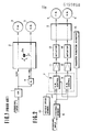
- Fig. 1 is a schematic view of a conventional type four-wheel steering system,
- Fig. 2 is a schematic view of a four-wheel steering control system of a first embodiment of the present invention,
- Figs. 3A and 3B are diagrams showing response characteristics of the front and rear wheels of the first embodiment,
- Figs. 4A and 4B are diagrams showing characteristics of the stationary gains shown in Figs. 3A and 3B,
- Fig. 5 is a schematic plan view of the system of the first embodiment,
- Fig. 6 is a schematic view of a four-wheel steering system of a second embodiment of the present invention,
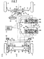
- Fig. 7 is a schematic plan view of the system of the second embodiment,
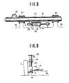
- Fig. 8 is a detailed sectional view of a front wheel steering mechanism shown in Fig. 7,
- Fig. 9 is an elevation of a rear wheel steering mechanism as viewed from a line IX-IX of Fig. 7 in a direction shown by arrows,
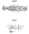
- Fig. 10 is a detailed sectional view of a rear wheel actuator shown in Fig. 9,
- Fig. 11 is a schematic plan view showing an alternative form of the front wheel steering mechanism for the second embodiment,
- Fig. 12 is a schematic view of a four-wheel steering system of a third embodiment of the present invention,
- Fig. 13 is a schematic plan view of the system of Fig. 12,
- Figs. 14A and 14B are diagrams showing front and rear wheel response characteristics of the third embodiment,
- Fig. 15 is a schematic view of a four-wheel steering system of a fourth embodiment of the present invention,
- Fig. 16 is a schematic plan view of the system of Fig. 15,
- Figs. 17A and 17B are diagrams showing front and rear wheel response characteristics of the fourth embodiment, and
- Figs. 18A and 18B are diagrams showing ideal transfer functions for the front wheels and rear wheels.
- Fig. 1 shows a four-wheel steering system of a conventional type as disclosed in Japanese Patent provisionally published application, provisional publication No. 58-20565. In this system, a steering input (which is a driver's steering command and which is usually a steering angle or
angular displacement 0 of a steering wheel) is transmitted through asteering gear 1 tofront road wheels 3 of avehicle 2, and simultaneously torear road wheels 5 through a rearwheel steering mechanism 4. A steering angle of thefront wheels 3 is maintained equal to asteering gear ratio 1/N of thesteering gear 1 times the steering input e, while at the same time a steering angle of therear wheels 5 is maintained equal to a gear ratio Kr of therear steering mechanism 4 times thegear ratio 1/N of thesteering gear 1 times the steering input e. That is, a transfer characteristic between the steering input and the front wheel steering angle and a transfer characteristic between the steering input and the rear wheel steering angle are fixed and substantially identical to each other from the viewpoint of an analysis of a turning movement of a wheeled vehicle. Therefore, this system cannot steer the front wheels and rear wheels individually in accordance with respective transfer characteristics and cannot provide a satisfactory cornering characteristic and steering stability of a vehicle. - The present invention is based on the following consideration.
- A turning movement of a wheeled vehicle is basically planar, and generally described by a yaw rate or yaw angular velocity ($ or ϕ) and a lateral acceleration (a) of the vehicle. The yaw rate is the time rate of change of angular displacement of the vehicle about a vertical axis through the center of gravity 2a of the
vehicle 2. The lateral acceleration is an acceleration of the center of gravity 2a along a lateral axis of the vehicle. - A movement of a vehicle having steerable front and steerable rear wheels is determined by the sum of a turning behavior due to a yaw rate φ1 and a lateral acceleration ai which are both caused by a steering angle δ1 of the front wheels, and a turning behavior due to a yaw rate φ2 and a lateral acceleration α2 which are both caused by a steering angle δ2 of the rear wheels. Therefore, a total yaw rate φ and a total lateral acceleration a of the vehicle are expressed as follows:
-


- By using a transfer function H1(s) between the front wheel steering angle δ1 and the yaw rate φ1 produced by this steering angle, a transfer function G1(s) between the front wheel steering angle δ1 and the lateral acceleration a1 produced by this steering angle, and similar transfer functions H2(s) and G2(s) relating the rear wheel steering angle δ2, respectively, to the resultant yaw rate ϕ2 and lateral acceleration a2, the quantities φ1, φ2, α1, α2 can be expressed, respectively, as follows:


- From the expression (1) to (6), the total yaw rate φ and the total lateral acceleration a are:


- By expressing a transfer function between the steering input e and the front
wheel steering angle 61, and a transfer function between the steering input θ and the rearwheel steering angle 62, respectively, as X1(s) and X2(s), the front and rear wheel steering angles δ1 and 62 are expressed as follows:

- Substitution of the front and rear wheel steering angles δi and δ2 expressed by the equations (9) and (10) into the equations (7) and (8) gives:


- It would be ideal if a vehicle could be steered in such a characteristic that there were neither phase lead nor phase lag of the behavior of the vehicle with respect to the steering input, and the gain of the vehicle such as a yaw rate gain would neither increase nor decrease with variation of the steering input. Therefore, it can be considered that satisfactory characteristics of the yaw rate and lateral acceleration can be obtained if the front and rear wheel steering angles are controlled so as to satisfy the following equations.


- It is possible to determine the transfer functions X1(s) and Xz(s) by using the equations (13) and (14).
- Division of both sides of the equations (11) and (12) by θ gives:


- From the euqations (15) and (16), the transfer functions Xi(s) and X2(s) are:


- In the equations (17) and (18), each of the transfer functions H1(s), H2(s), G1(s) and G2(s) is known per se. For example, Masato Abe "Sharyo no Undo to Seigyo (Movement and Control of Vehicle)" Kyoritsu Shuppan Kabushiki Kaisha, discloses these transfer functions. The description of this publication necessary to determine these transfer functions is hereby incorporated by reference. Thus, the transfer functions H1(s), H2(s), G1(s) and G2(s) can be determined easily, so that the transfer functions Xi(s) and X2(s) to obtain the desired values φ0, ao can be determined from the equations (17) and (18).
- Because each of the transfer functions is a function of a steering frequency, the sign s of each transfer function can be replaced by Jw, provided that J is an imaginary number, and w is the steering frequency. Therefore, the transfer functions Xi(s) and X2(s) obtained from the equations (17) and (18) provide frequency response characteristics of both gain and phase difference as shown in Figs. 18A and 18B.
- As is known, each of the transfer functions Hi(s), H2(s), Gi(s) and G2(s) is a function of the vehicle speed. Accordingly, each characteristic of Figs. 18A and 18B changes from a broken line curve to a solid line curve with increase of the vehicle speed as shown by an arrow. As shown in Fig. 18A, both of the gain and the phase lead of Xi(s) decrease when the vehicle speed increases. The gain of Xz(s) changes from a negative side to a positive side with increase of the vehicle speed, as shown in Fig. 18B. The phase difference of Xz(s) changes from a phase lead side to a phase lag side with increase of the vehicle speed as shown in Fig. 18B.
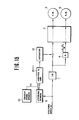
- A first embodiment of the present invention is shown in Fig. 2. A control system of the first embodiment for steering a
vehicle 2 throughfront wheels 3 andrear wheels 5 has asteering sensor 6 which senses a steering input produced by a driver. The steering input is an angular displacement e of a steering wheel of thevehicle 2, for example. Thesteering sensor 6 is connected to acontrol unit 7 which has a front wheel steeringangle control circuit 8 and a rear wheel steeringangle control circuit 9. Both circuits of thecontrol unit 7 receives a signal of avehicle speed sensor 10 as well as a signal of thesteering input sensor 6. - The
vehicle speed sensor 10 senses a speed V of thevehicle 2. Thecontrol unit 7 determines the above-mentioned transfer functions Hi(s), Hz(s), Gi(s) and G2(s) from the vehicle speed V sensed by thevehicle speed sensor 10 and a steering frequency based on the steering input θ. By using these transfer functions, the front wheel steeringangle control circuit 8 determines the transfer function Xi(s) corresponding to the desired values φ0 and ao from the above-mentioned equation (17). Then, thefront wheel circuit 8 determines the steering angle δ1 of thefront wheels 3 from the above-mentioned equation (9) by use of Xi(s) and the steering input θ. Similarly, the rear wheel steeringangle control circuit 9 determines the transfer function Xz(s) corresponding to the desired values φ0 and ao from the equation (18), and then determines the steering angle δ2 of therear wheels 5 from the equation (10). - An output signal of the
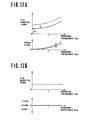
circuit 8, indicative of the frontwheel steering angle 61, is sent to afront wheel actuator 13 through anamplifier 11 for amplifying the signal. An output signal of thecircuit 9, indicative of the rearwheel steering angle 62 is sent to arear wheel actuator 14 through anamplifier 12. Theactuator 13 steers thefront wheels 3 through the determined steering angle δ1 in accordance with the output signal of thecircuit 8. Theactuator 14 steers therear wheels 5 through thedetermined steering angle 62 in accordance with the output signal of thecircuit 9. Thus, thevehicle 2 is steered through both the front and rear wheels so that the desired values φ0 and ao expressed by the equations (13) and (14) can be obtained. Consequently, the steering control system of the first embodiment can improve the vehicle stability and control (or directional control characteristics) remarkably, and make an ideal four-wheel steering possible. - This control system employs the transfer functions X1(s) and X2(s) as shown in Figs. 18A and 18B. Therefore, the response characteristic of the front wheel steering angle is determined by X (s), as shown in Fig. 3A. Each characteristic curve of Fig. 3A changes from a broken line to a solid line when the vehicle speed becomes high. As shown, the
front wheels 3 are turned in such a positive direction as to increase a direction change of the vehicle. An amount of a turn of the front wheels in the positive direction is decreased as the steering frequency decreases, or as the vehicle speed increases. The response of thefront wheels 3 leads the steering input, and the phase lead of thefront wheels 3 with respect to the steering input is decreased as the steering frequency decreases or as the vehicle speed increases. The response characteristic of the rear wheel steering angle is determined by X2(s), as shown in Fig. 3B. Each characteristic curve of Fig. 3B changes from a broken line to a solid line when the vehicle speed becomes high. When the vehicle speed is low, therear wheels 5 are turned in the positive direction to increase the direction change of the vehicle. (That is, therear wheels 5 are turned in a direction opposite to a turn direction of thefront wheels 3 with respect to a longitudinal line of the vehicle). When the vehicle speed is high, therear wheels 5 are turned in such a negative direction as to decrease a direction change of the vehicle. (That is, therear wheels 5 are turned in the same direction as thefront wheels 3 are turned). The response of therear wheels 5 leads the steering input when the vehicle speed is low, and lags the steering input when the vehicle speed is high. - In Figs. 3A and 3B, G1 and G2 are, respectively, values (stationary gains) of the gains of the
front wheels 3 andrear wheels 5 when the steering frequency is approximately zero. The values G1 and G2 vary with the vehicle speed as shown in Figs. 4A and 4B. As shown by a solid line in Fig. 4A, the amount of a turn of thefront wheels 3 in the positive direction decreases when the vehicle speed becomes high. The amount of a turn of therear wheels 5 in the positive or negative direction is varied as shown by a solid line in Fig. 4B. A broken line of Fig. 4A shows a characteristic obtained when the control of the amount of a turn of the front wheels in the positive direction based on the vehicle speed is not performed. A broken line of Fig. 4B shows a characteristic obtained when the rear wheels are controlled only in the negative direction without a control in the positive direction. The direction control characteristic of the vehicle can be improved even when the characteristics of the broken lines of Figs. 4A and 4B are employed. - It is preferable to incorporate a
transfer function adjuster 15 for modifying the transfer functions Xi(s) and Xz(s), into the control system of this embodiment, as shown in Fig. 2. A yaw rate gain of the vehicle is determined by the transfer functions X1(s) and X2(s). Therefore, theadjuster 15 is arranged to adapt the yaw rate gain of the vehicle to vehicle speed, side wind, weather condition, road condition, acceleration or deceleration of the vehicle, vehicle weight, weight distribution between the front and rear axles, and/or driver's taste, by modifying X1(s) and/or X2(s). - When the vehicle speed is employed, the
transfer function adjuster 15 is arranged to decrease the yaw rate gain (a ratio of the yaw rate to the steering input) with increase of the vehicle speed in order to improve the vehicle stability at high vehicle speeds. Therefore, theadjuster 15 decreases the transfer function X1(s) (the amount of a turn of the front wheels in the positive direction) determined by thecontrol circuit 8, and increases the transfer function X2(s) (the amount of a turn of the rear wheels in the negative direction) determined by thecircuit 9, as the vehicle speed increases. - The
transfer function adjuster 15 may be arranged to decrease the yaw rate gain by decreasing Xi(s) and increasing X2(s) when any one or more of conditions of side wind, weather and road surface become worse for the vehicle control and stability. For example, the yaw rate gain is decreased when the side wind becomes stronger, when the weather becomes rainy, or when the road becomes rugged. - It is desirable to decrease the yaw rate gain of the vehicle with increase of the time rate of change of the vehicle speed (acceleration or deceleration of the vehicle) because the tendency to power- slide of the vehicle increases with increase of the vehicle acceleration, and the tendency to tack-in of the vehicle increases with increase of the vehicle deceleration. Therefore, the
adjuster 15 may be arranged to decrease Xi(s) and increase X2(s) as the vehicle acceleration or deceleration increases. When the vehicle weight increases, lateral grip of the tires of the vehicle becomes deficient so that the vehicle control becomes unstable. Therefore, theadjuster 15 may be arranged to decrease the yaw rate gain with increase of the vehicle weight. When the weight on the rear axle increases as compared with the weight on the front axle, the rear of the vehicle tends to slide outwardly under the influence of a centrifugal force produced by a turn of the vehicle. Therefore, theadjuster 15 may be arranged to decrease the yaw rate gain as the weight on the rear axle increases. - It is possible to decrease the yaw rate gain by decreasing the phase lead of Xi(s) and increasing the phase lag of X2(s), as evident from Figs. 3A and 3B. Therefore, the
adjuster 15 may be arranged to adjust the phase differences in either case. - When a driver's taste is employed, the
adjuster 15 modifies X1(s) and X2(s) so as to adjust the yaw rate gain to a value indicated by a driver's manual operation. - Fig. 5 shows the control system of Fig. 2 more concretely. Right and left
steering linkages 16 supports the right and leftfront wheels 3, respectively, on a vehicle body so that thefront wheels 3 are steerable. Right and leftsteering linkages 17 support therear wheels 5, respectively, on the vehicle body so that therear wheels 5 are also steerable. Thefront wheel actuator 13 shown in Fig. 2 is interposed between thefront steering linkages 16. Therear wheel actuator 14 is interposed between therear steering linkage 17. Each of theactuators actuators servo valves - A hydraulic fluid pressure is supplied to the
servo valves oil pump 22 is driven by anengine 20 which is mounted on the vehicle together with atransmission 21. Theoil pump 22 sucks oil from anoil reservoir 23, and discharges the oil to an unloadvalve 24, which controls the pressure of the oil at a predetermined value and supplies the pressurized oil to anaccumulator 25. The oil is supplied from theaccumulator 25 to theservo valves supply conduit 26. Areturn conduit 27 conveys an unnecessary oil from theservo valves valve 24. - The
steering sensor 6 senses the angular displacement θ of thesteering wheel 30, and thevehicle speed sensor 10 senses an output rpm of the transmission 21 (vehicle speed V). The front and rear wheel steeringangle control circuits control unit 7 receives the steering input 0 sensed by thesteering sensor 6, and the vehicle speed V sensed by thevehicle speed sensor 10, and produces the output electric signals indicative of the front and rear wheel steering angles 61 and 62, respectively. The output signals of thecircuits amplifiers servo valves - In accordance with the output signal of the
control circuit 8, thefront servo valve 18 supplies the oil of thesupply conduit 26 to one of two working chambers of thefront wheel actuator 13 and makes the other chamber open to thereturn conduit 27, so that the piston of theactuator 13 moves in a direction determined by the signal of thecontrol circuit 8, and steers thefront wheels 3 in the determined direction. Similarly, theservo valve 19 steers therear wheels 5 by supplying the oil from thesupply conduit 26 to one of two working chambers of therear wheel actuator 14 in accordance with the signal of thecontrol circuit 9. Front and rear wheelsteering angle sensors rear wheels steering angle sensor 28 is compared with the signal of thecontrol circuit 8, and theservo valve 18 stops its control when the sensed amount of the angular displacement of thefront wheels 3 is equal to the front wheel steering angle g 1 determined by thecircuit 8. Similarly, therear servo valve 19 stops its control when the amount of the angular displacement of therear wheels 5 is equal to the rear wheel steering angle δ2 determined by thecircuit 9. Theservo valves rear wheels actuator conduits - A second embodiment of the present invention is shown in Fig. 6. The rear wheel steering system of this embodiment is the same as that of the first embodiment. The front wheel steering system of this embodiment is different from that of the first embodiment in that the
front wheels 3 are steered first through amechanical steering gear 1, and secondly through anelectrical control circuit 8 similar to thecontrol circuit 8 of the first embodiment. In the second embodiment, the desired frontwheel steering angle 61 is attained by a cooperation of the steering mechanism and the control circuit. Unlike the first embodiment, the front wheel steeringangle control circuit 8 of the second embodiment uses a value X1' obtained by subtracting a transfer function X1(s)' of the front wheel steering mechanism including thesteering gear 1 from the transfer function Xi(s) obtained from the above-mentioned equation (17) (i.e. Xi' = Xi(s) - X1(s)'), and determines a corrective steering angle δ1' for thefront wheels 3 from an equation δ1' = θ • X1' which corresponds to the equation (9). Thecontrol circuit 8 steers thefront wheels 3 through theamplifier 11 and thefront wheel actuator 13 in accordance with the determined corrective steering angle 61' in such a manner as to give assistance to the front wheel steering mechanism. - Fig. 7 shows the control system of Fig. 6 concretely. The
steering gear 1 of the front wheel steering mechanism has arack 31 interposed between right and leftsteering linkages 16 of the right and leftfront wheels 3, and apinion 32 which is rotated by asteering wheel 30 and in engagement with therack 31. Asteering gear housing 33 encloses therack 31 andpinion 32. Thesteering input 0 applied to thesteering wheel 30 by the driver causes thepinion 32 to rotate, and therack 31 to move longitudinally (toward the right or left front wheel 3), so that thefront wheels 3 are steered. In order to apply a control action of thecontrol circuit 8 to the steering mechanism, thegear housing 33 is supported on avehicle body 35 throughrubber bushes 34, and made longitudinally movable together with therack 31, relative to the vehicle body, toward the right or leftfront wheel 3, by thefront wheel actuator 13 of a hydraulic type. - As shown in Fig. 8, the
front wheel actuator 13 has apiston 13a which separates two working chambers having ports A and B, respectively. Theactuator 13 further has apiston rod 13b connected with thegear housing 33. The cylinder of theactuator 13 is connected with thevehicle body 35 through a rod 13c. Theactuator 13 is controlled by a frontelectromagnetic spool valve 36F having solenoids spool 36c. Thespool 36c is held at a neutral position shown in Fig. 7 by springs when both of thesolenoids valve 36F is connected with anoil pump 22 and areservoir 23. Thevalve 36F has a port A' connected with the port A of thefront wheel actuator 13, and a port B' connected with the port B of theactuator 13. - The
solenoid amplifier 11 from the front wheel steeringangle control circuit 8 responsive to thesteering input 0 sensed by thesteering sensor 6 and the vehicle speed V sensed by thevehicle speed sensor 10. When thesolenoid 36a is energized and thespool 36c of thevalve 36F is moved left in Fig. 7, the fluid pressure is supplied through the port B', and accordingly thepiston 13a of theactuator 13 is moved left as shown by an arrow C in Fig. 8. Therefore, thegear housing 33 causes therubber bushes 34 to deflect, and moves left in Fig. 7, so that thefront wheels 3 are steered right. When thesolenoid 36b of thevalve 36F is energized and thespool 36c is moved right in Fig. 7, the fluid pressure is supplied through the port A' so that thefront wheels 3 are steered left. Thecontrol circuit 8 controls the direction and amount of the corrective steering action of theactuator 13. A front wheelsteering angle sensor 28 senses the corrective control action of theactuator 13. Thevalve 36F is so arranged that the actual amount sensed by thesensor 28 is maintained equal to the desired corrective steering angle 61'. - The rear wheel steering system of Fig. 7 has right and left
wheel support member 38 which, respectively, support therear wheels 5 rotatably. Each of thewheel support members 38 is supported on thevehicle body 35 by aradius rod 39 in the fore and aft direction of the vehicle, and by a pair of parallellateral rods strut assembly 42 having asuspension spring 43 extends upwardly from eachwheel support member 38 to thevehicle body 35. - The
lateral rod 40 of each rear wheel is provided with theactuator 14 of a hydraulic cylinder type so that a toe angle of therear wheel 5 can be varied. Fig. 10 shows theactuator 14 for the leftrear wheel 5. As shown in Fig. 10, theactuator 14 has a piston 14a separating two working chambers having, respectively, ports A and B, and apiston rod 14b. Thelateral rod 40 is divided into anouter portion 40a and aninner portion 40b. Thepiston rod 14b is placed between the outer and innerlateral rod portions circular disc 44 is interposed between the outerlateral rod portion 40a and thepiston rod 14b coaxially. Thepiston rod 14b, thedisc 44 and the outerlateral rod portion 40a are fixed together so as to form a single integral unit. The cylinder of theactuator 14 is fixed with the innerlateral rod portion 40b.Annular rubber bushes disc 44. Atubular case 47 is fixed with the cylinder of theactuator 14. Thetubular case 47 encloses therubber bushes - An outboard end of the outer
lateral rod portion 40a is connected with thewheel support member 38 through arubber bush 49 and apin 48 fixed to thesupport member 38 as an outboard end of thelateral rod 41. An inboard end of the innerlateral rod portion 40b is connected with thevehicle body 35 through arubber bush 51 and apin 50 fixed to thevehicle body 35 as an inboard end of thelateral rod 41. - The left and
right actuators 14 for the left and rightrear wheels 5 are controlled by a rearelectromagnetic spool valve 36R similar to thefront valve 36F. A port A' of therear valve 36R is connected to the outboard port B of theleft actuator 14 for the leftrear wheel 5 and the inboard port A of theright actuator 14 for the rightrear wheel 5. A port B' of therear valve 36R is connected to the inboard port A of theleft actuator 14 for the leftrear wheel 5, and the outboard port B of theright actuator 14 for the rightrear wheel 5. - The electric signal indicative of the rear
wheel steering angle 62, produced by thecontrol circuit 9 is sent through theamplifier 12 to thevalve 36R. Asolenoid 36a or asolenoid 36b of thevalve 36R is selectively energized by the signal of thecircuit 9. When thesolenoid 36b is energized and thespool 36c is moved right in Fig. 7, thevalve 36R supplies the fluid pressure through the port A' to the outboard port B of the leftrear wheel actuator 14 and the inboard port A of the rightrear actuator 14. Therefore, thepiston rod 14b of the leftrear wheel actuator 14 moves right in Fig. 10 and compresses therubber bush 46, so that the leftrear wheel actuator 14 shortens. Consequently, the leftrear wheel 5 is steered to a position shown by a two-dot chain line in Fig. 7. At the same time, the rightrear actuator 14 is lengthened, so the rightrear wheel 5 is steered in the same direction as the leftrear wheel 5. When thesolenoid 36a of thevalve 36R is energized, thevalve 36R moves itsspool 36c left in Fig. 7 and supplies the fluid pressure through the port B' to the inboard port A of the leftrear wheel actuator 14 and the outboard port B of the rightrear wheel actuator 14. Therefore, the rightrear wheel 5 is steered to a position shown by a two-dot chain line in Fig. 7 by a contraction of the rightrear wheel actuator 14, and at the same time the leftrear wheel 5 is steered in the same direction by an expansion of the leftrear wheel actuator 14. A rear wheelsteering angle sensor 29 senses the steering angle of therear wheels 5 by sensing a stroke of one of theactuators 14. Thecontrol circuit 9 controls steering direction and amount of the rear wheels, and thevalve 36R maintains the steering angle sensed by thesensor 29 equal to the desiredsteering angle 62. - It is optional to employ a front wheel steering system shown in Fig. 11 in place of the front wheel steering system shown in Fig. 7. In this example, right and left
steering linkages 16 of the right and left front wheels are connected with each other by atie rod 52. Thetie rod 52 is liked to thevehicle body 35 through alink 53. Thesteering gear 1 of Fig. 11 is a recirculating ball type. A pitman arm 1a of thesteering gear 1 is connected to thetie rod 52 through thefront wheel actuator 13. - This
actuator 13 is a hydraulic servo actuator. In accordance with the signal of thecontrol circuit 8, theactuator 13 is expanded and contracted. Thus, theactuator 13 can steer thefront wheels 3 in addition to a steering action of thesteering gear 1. When there is no steering action of theactuator 13, thefront wheels 3 are steered only by a turning movement transmitted through thesteering gear 1,actuator 13,tie rod 52 andlinkages 16. - A third embodiment of the present invention is shown in Fig. 12. The front wheel steering system of this embodiment is the same as that of Fig. 6. The rear wheel steering system of the third embodiment is arranged to steer the
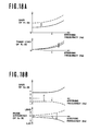
rear wheels 5 by supplying the fluid pressure outputted by theelectromagnetic valve 36 of the front wheel steering system, to therear wheel actuator 14 through a delay means 54 such as an orifice. As shown in Fig. 13, the front wheel steering mechanism, thefront wheel actuator 13, and the right and leftrear wheel actuators 14 of the third embodiment are arranged in the same manners those shown in Figs. 7 to 10. In the third embodiment, however, the port A of thefront wheel actuator 13 is connected by aconduit 55 with the outboard port B of the leftrear wheel actuator 14, and the inboard port A of the rightrear wheel actuator 14. The port B of thefront wheel actuator 13 is connected by aconduit 56 with the inboard port A of the leftrear wheel actuator 14, and the outboard port B of the rightrear wheel actuator 14. The delay means 54 has an orifice disposed in theconduit 55 for restricting the flow through theconduit 55 and an orifice disposed in theconduit 56 for restricting the flow 'through theconduit 56. - In the third embodiment, the front wheels are steered in accordance with the characteristics shown in Fig. 14A, which are similar to the characteristics of Fig. 3A for the preceding embodiments. However, the response characteristics of the rear wheels of the third embodiment shown in Fig. 14B are different from those of the preceding embodiments. As shown in Fig. 14B, the steering direction of the rear wheels is always negative. The rear wheels are steered in the negative direction even when the vehicle speed is low. The amount of a turn of the rear wheels in the negative direction is increased as the vehicle speed increases as shown by an arrow in Fig. 14B. However, this amount is not increaed even in a high steering frequency range because there is provided the delay means 54. The phase of the rear wheel response is equal to the phase lead of the front wheels minus a phase lag due to the delay means 54. By making the opening size of the orifices of the delay means 54 sufficiently small, it is possible to obtain such a characteristic that the phase difference is changed from the phase lead shown by a broken line to the phase lag shown by a solid line in Fig. 14B when the vehicle speed becomes high, as shown by an arrow in Fig. 14B.
- A fourth embodiment of the present invention is shown in Fig. 15. The front wheel steering system of the fourth embodiment is the same as those of the second and third embodiments. The rear wheel steering system consists of a rear
wheel steering mechanism 4 similar to that of Fig. 1. The system of the fourth embodiment is shown concretely in Fig. 16. Like the second and third embodiments, the front wheel steering system of this embodiment has the rack and piniontype steering gear 1 and thefront wheel actuator 13 for moving thesteering gear housing 33. The front wheels are controlled by theactuator 13,control circuit 8,amplifier 11,electromagnetic spool valve 36 in the same manner as explained with reference to Figs. 6 to 8. The rearwheel steering mechanism 4 has right and leftsteering linkages 57 supporting the right and leftrear wheels 5, respectively, so that the rear wheels are steerable. The rearwheel steering mechanism 4 further has arack 58 interposed between the right and leftlinkages 57 for connecting both, and apinion 59 engaging with therack 58. Thepinion 59 is fixed to one end of theshaft 61. The other end of theshaft 61 has apinion 60 fixed thereto. Thepinion 60 is engaged with therack 31 of the frontwheel steering gear 1. Therefore, a turning motion of thesteering wheel 30 is transmitted through therack 31,pinion 60,shaft 61,pinion 59,rack 58, andsteering linkages 57 to the rear wheels. The rearwheel steering mechanism 4 is so arranged that therear wheels 5 are steered in the same direction with respect to the longitudinal line of the vehicle as thefront wheels 3. - The response characteristics of the fourth embodiment are shown in Figs. 17A and 17B. The response characteristics of the front wheels are similar to those of the preceding embodiments, as shown in Fig. 17A. The rear wheel response characteristics is shown in Fig. 17B. The
rear wheels 5 are steered only in the negative direction which is the same direction as the steered direction of thefront wheels 3. The amount of a turn of therear wheels 5 in the negative direction is affected by neither the vehicle speed nor the steering frequency, but it is determined only by the steering input. The phase difference of the rear wheels is always zero because of the construction of the rearwheel steering mechanism 4. - Thus, according to the present invention, the transfer characteristic (the transfer function Xi(s)) between the steering input and the front wheel steering angle, and the transfer characteristic (the transfer function X2(s)) between the steering input and the rear wheel steering angle are differentiated from each other so as to improve the directional control and stability of the vehicle. Therefore, the present invention makes it possible to obtain an ideal flat characteristic of the gain of vehicle (which is a ratio of the raw rate or lateral acceleration of the vehicle to the steering input), and to make the phase lag of the vehicle (which is a time delay between the steering input and the yaw rate or lateral acceleration of the vehicle) substantially zero.
Claims (23)
wherein the rear steering means turns the rear wheels in the same direction as the front wheels at least in the high vehicle speed range.
Applications Claiming Priority (2)
| Application Number | Priority Date | Filing Date | Title |
|---|---|---|---|
| JP59015342A JPS60161265A (en) | 1984-01-31 | 1984-01-31 | Steering for car |
| JP15342/84 | 1984-01-31 |
Publications (3)
| Publication Number | Publication Date |
|---|---|
| EP0150858A2 true EP0150858A2 (en) | 1985-08-07 |
| EP0150858A3 EP0150858A3 (en) | 1986-02-05 |
| EP0150858B1 EP0150858B1 (en) | 1988-11-17 |
Family
ID=11886114
Family Applications (1)
| Application Number | Title | Priority Date | Filing Date |
|---|---|---|---|
| EP85101023A Expired EP0150858B1 (en) | 1984-01-31 | 1985-01-31 | Four-wheel steering control system for vehicle |
Country Status (4)
| Country | Link |
|---|---|
| US (1) | US4705131A (en) |
| EP (1) | EP0150858B1 (en) |
| JP (1) | JPS60161265A (en) |
| DE (1) | DE3566239D1 (en) |
Cited By (8)
| Publication number | Priority date | Publication date | Assignee | Title |
|---|---|---|---|---|
| EP0165706A2 (en) * | 1984-05-21 | 1985-12-27 | Kabushiki Kaisha Toyota Chuo Kenkyusho | Apparatus for controlling steer angle of rear wheels of vehicle |
| EP0199347A1 (en) * | 1985-04-25 | 1986-10-29 | Kabushiki Kaisha Toyota Chuo Kenkyusho | Apparatus for controlling steer angle of rear wheels of vehicle |
| EP0249967A2 (en) * | 1986-06-20 | 1987-12-23 | Toyota Jidosha Kabushiki Kaisha | Apparatus for controlling a steering angle of a rear wheel |
| EP0254248A1 (en) * | 1986-07-19 | 1988-01-27 | Bayerische Motoren Werke Aktiengesellschaft, Patentabteilung AJ-3 | Rear wheel steering for motor vehicles |
| FR2604680A1 (en) * | 1986-10-01 | 1988-04-08 | Daimler Benz Ag | MOTOR VEHICLE WITH FRONT WHEEL DIRECTION AND REAR WHEEL DIRECTION, IN PARTICULAR A FOUR WHEEL DIRECTION |
| EP0316002A2 (en) * | 1987-11-12 | 1989-05-17 | Nissan Motor Co., Ltd. | Method of steering vehicle |
| EP0338202A2 (en) * | 1988-04-19 | 1989-10-25 | Dr.Ing.h.c. F. Porsche Aktiengesellschaft | Active four wheel steering system for automotive vehicles |
| US5143400A (en) * | 1989-08-10 | 1992-09-01 | Michelin Recherche Et Technique | Active toe adjustment apparatus |
Families Citing this family (27)
| Publication number | Priority date | Publication date | Assignee | Title |
|---|---|---|---|---|
| JPS62152975A (en) * | 1985-12-27 | 1987-07-07 | Isuzu Motors Ltd | Method and device for steering four wheel |
| JPS63287674A (en) * | 1987-05-19 | 1988-11-24 | Nissan Motor Co Ltd | Steering angle control device for vehicle |
| JPH0825470B2 (en) * | 1987-05-20 | 1996-03-13 | 日産自動車株式会社 | Rear wheel rudder angle control method |
| DE3825885A1 (en) * | 1987-07-29 | 1989-02-16 | Honda Motor Co Ltd | METHOD AND DEVICE FOR CONTROLLING THE STEERING PROCESS OF A MOTOR VEHICLE WITH STEERING FRONT AND REAR WHEELS |
| JP2532107B2 (en) * | 1987-10-08 | 1996-09-11 | 日産自動車株式会社 | Steering control device for four-wheel steering vehicle |
| JPH01202577A (en) * | 1988-02-06 | 1989-08-15 | Nissan Motor Co Ltd | Steering angle control device for vehicle |
| JP2505240B2 (en) * | 1988-02-24 | 1996-06-05 | 日産自動車株式会社 | 4-wheel steering control device |
| JP2603289B2 (en) * | 1988-03-28 | 1997-04-23 | 本田技研工業株式会社 | Steering control device for front and rear wheel steering vehicles |
| DE3915448A1 (en) * | 1988-05-16 | 1989-11-23 | Fuji Heavy Ind Ltd | METHOD FOR REGULATING THE REAR WHEEL STEERING ADJUSTMENT IN A MOTOR VEHICLE WITH FOUR WHEEL STEERING |
| JPH0231976A (en) * | 1988-07-20 | 1990-02-01 | Nissan Motor Co Ltd | Auxiliary steering device for vehicle |
| US5156229A (en) * | 1988-09-13 | 1992-10-20 | Aisin Seiki Kabushiki Kaisha | Steering control apparatus |
| US5313389A (en) * | 1988-09-13 | 1994-05-17 | Aisin Seiki Kabushiki Kaisha | Fail-safe mechanism for vehicle stability augmentation steering system |
| US5141069A (en) * | 1988-09-13 | 1992-08-25 | Aisin Seiki Kabushiki Kaisha | Steering mechanism with toe-in control |
| JPH02124371A (en) * | 1988-10-31 | 1990-05-11 | Mitsubishi Automob Eng Co Ltd | Steering device of vehicle |
| US5003480A (en) * | 1989-05-29 | 1991-03-26 | Nissan Motor Co., Ltd. | Four wheel steering system for vehicle |
| US5086861A (en) * | 1990-04-06 | 1992-02-11 | Peterson Donald W | Electric rear wheel steering actuator |
| JPH04133860A (en) * | 1990-09-25 | 1992-05-07 | Honda Motor Co Ltd | Control method for vehicle steering device |
| US5224042A (en) * | 1991-02-19 | 1993-06-29 | General Motors Corporation | Four wheel steering system with speed-dependent phase reversal |
| JP3211434B2 (en) * | 1991-12-18 | 2001-09-25 | アイシン精機株式会社 | Vehicle guidance control device |
| US5438515A (en) * | 1992-10-14 | 1995-08-01 | Mitsubishi Jidosha Kogyo Kabushiki Kaisha | Alignment control unit and control method for an automotive suspension |
| JP2001334949A (en) * | 2000-05-26 | 2001-12-04 | Aisin Seiki Co Ltd | Rear wheel steering control device |
| JP4846387B2 (en) * | 2006-02-23 | 2011-12-28 | 文化シヤッター株式会社 | Door device |
| KR101427941B1 (en) * | 2012-12-06 | 2014-08-08 | 현대자동차 주식회사 | Behavior control system for vehicle and method thereof |
| CN106347453B (en) * | 2016-10-26 | 2018-08-21 | 中车戚墅堰机车有限公司 | Intelligent combined 4 wheel driven tractor |
| US11731691B2 (en) * | 2019-09-11 | 2023-08-22 | Super ATV, LLC | Rear end steering and mounting system |
| JP7322911B2 (en) * | 2021-02-24 | 2023-08-08 | トヨタ自動車株式会社 | Vehicle control method, vehicle control system, and vehicle |
| CN116588187B (en) * | 2023-07-18 | 2023-12-15 | 博世汽车部件(苏州)有限公司 | Control method and device for lane keeping function |
Citations (6)
| Publication number | Priority date | Publication date | Assignee | Title |
|---|---|---|---|---|
| US4105086A (en) * | 1975-11-13 | 1978-08-08 | Takemochi Ishii | System for controlling vehicular four-wheel steering mechanisms |
| FR2445257A1 (en) * | 1978-12-29 | 1980-07-25 | Honda Motor Co Ltd | STEERING DEVICE FOR VEHICLES |
| GB2083422A (en) * | 1980-08-27 | 1982-03-24 | Honda Motor Co Ltd | Vehicle steering mechanisms |
| DE3145618A1 (en) * | 1980-11-18 | 1982-06-03 | Nissan Motor Co., Ltd., Yokohama, Kanagawa | METHOD AND SYSTEM FOR STEERING A CYCLING VEHICLE |
| FR2510506A1 (en) * | 1981-07-28 | 1983-02-04 | Honda Motor Co Ltd | STEERING SYSTEM FOR TURNING THE FRONT AND REAR WHEELS OF A VEHICLE |
| EP0089631A2 (en) * | 1982-03-24 | 1983-09-28 | Nissan Motor Co., Ltd. | Steering control system for automotive vehicle or the like |
Family Cites Families (5)
| Publication number | Priority date | Publication date | Assignee | Title |
|---|---|---|---|---|
| JPS5711173A (en) * | 1980-06-24 | 1982-01-20 | Nissan Motor Co Ltd | Method of controlling steering angle for vehicle capable of steering two sets of wheels |
| US4440254A (en) * | 1980-12-10 | 1984-04-03 | Nissan Motor Co., Ltd. | Compliance steer control system |
| US4373603A (en) * | 1981-03-05 | 1983-02-15 | J. I. Case Company | Automatic crab steering |
| JPS5820565A (en) * | 1981-07-28 | 1983-02-07 | Honda Motor Co Ltd | Steering gear for vehicle |
| JPS5970259A (en) * | 1982-10-13 | 1984-04-20 | Honda Motor Co Ltd | Steering device of vehicle |
-
1984
- 1984-01-31 JP JP59015342A patent/JPS60161265A/en active Granted
-
1985
- 1985-01-28 US US06/695,345 patent/US4705131A/en not_active Expired - Lifetime
- 1985-01-31 DE DE8585101023T patent/DE3566239D1/en not_active Expired
- 1985-01-31 EP EP85101023A patent/EP0150858B1/en not_active Expired
Patent Citations (6)
| Publication number | Priority date | Publication date | Assignee | Title |
|---|---|---|---|---|
| US4105086A (en) * | 1975-11-13 | 1978-08-08 | Takemochi Ishii | System for controlling vehicular four-wheel steering mechanisms |
| FR2445257A1 (en) * | 1978-12-29 | 1980-07-25 | Honda Motor Co Ltd | STEERING DEVICE FOR VEHICLES |
| GB2083422A (en) * | 1980-08-27 | 1982-03-24 | Honda Motor Co Ltd | Vehicle steering mechanisms |
| DE3145618A1 (en) * | 1980-11-18 | 1982-06-03 | Nissan Motor Co., Ltd., Yokohama, Kanagawa | METHOD AND SYSTEM FOR STEERING A CYCLING VEHICLE |
| FR2510506A1 (en) * | 1981-07-28 | 1983-02-04 | Honda Motor Co Ltd | STEERING SYSTEM FOR TURNING THE FRONT AND REAR WHEELS OF A VEHICLE |
| EP0089631A2 (en) * | 1982-03-24 | 1983-09-28 | Nissan Motor Co., Ltd. | Steering control system for automotive vehicle or the like |
Cited By (14)
| Publication number | Priority date | Publication date | Assignee | Title |
|---|---|---|---|---|
| US4720790A (en) * | 1984-05-21 | 1988-01-19 | Kabushiki Kaisha Toyota Chuo Kenkyusho | Apparatus for controlling steer angle of rear wheels of vehicle |
| EP0165706A2 (en) * | 1984-05-21 | 1985-12-27 | Kabushiki Kaisha Toyota Chuo Kenkyusho | Apparatus for controlling steer angle of rear wheels of vehicle |
| EP0165706B1 (en) * | 1984-05-21 | 1988-08-10 | Kabushiki Kaisha Toyota Chuo Kenkyusho | Apparatus for controlling steer angle of rear wheels of vehicle |
| EP0199347A1 (en) * | 1985-04-25 | 1986-10-29 | Kabushiki Kaisha Toyota Chuo Kenkyusho | Apparatus for controlling steer angle of rear wheels of vehicle |
| US4700960A (en) * | 1985-04-25 | 1987-10-20 | Kabushiki Kaisha Toyota Chuo Kenkyusho | Apparatus for controlling steer angle of rear wheels of vehicle |
| EP0249967A3 (en) * | 1986-06-20 | 1989-03-08 | Toyota Jidosha Kabushiki Kaisha | Apparatus for controlling a steering angle of a rear wheel |
| EP0249967A2 (en) * | 1986-06-20 | 1987-12-23 | Toyota Jidosha Kabushiki Kaisha | Apparatus for controlling a steering angle of a rear wheel |
| EP0254248A1 (en) * | 1986-07-19 | 1988-01-27 | Bayerische Motoren Werke Aktiengesellschaft, Patentabteilung AJ-3 | Rear wheel steering for motor vehicles |
| FR2604680A1 (en) * | 1986-10-01 | 1988-04-08 | Daimler Benz Ag | MOTOR VEHICLE WITH FRONT WHEEL DIRECTION AND REAR WHEEL DIRECTION, IN PARTICULAR A FOUR WHEEL DIRECTION |
| EP0316002A2 (en) * | 1987-11-12 | 1989-05-17 | Nissan Motor Co., Ltd. | Method of steering vehicle |
| EP0316002A3 (en) * | 1987-11-12 | 1990-08-29 | Nissan Motor Co., Ltd. | Method of steering vehicle |
| EP0338202A2 (en) * | 1988-04-19 | 1989-10-25 | Dr.Ing.h.c. F. Porsche Aktiengesellschaft | Active four wheel steering system for automotive vehicles |
| EP0338202A3 (en) * | 1988-04-19 | 1990-11-07 | Dr.Ing.H.C. F. Porsche Aktiengesellschaft | Active four wheel steering system for automotive vehicles |
| US5143400A (en) * | 1989-08-10 | 1992-09-01 | Michelin Recherche Et Technique | Active toe adjustment apparatus |
Also Published As
| Publication number | Publication date |
|---|---|
| EP0150858B1 (en) | 1988-11-17 |
| EP0150858A3 (en) | 1986-02-05 |
| US4705131A (en) | 1987-11-10 |
| JPH0446792B2 (en) | 1992-07-31 |
| JPS60161265A (en) | 1985-08-22 |
| DE3566239D1 (en) | 1988-12-22 |
Similar Documents
| Publication | Publication Date | Title |
|---|---|---|
| EP0150858B1 (en) | Four-wheel steering control system for vehicle | |
| EP0150857B1 (en) | Steering control system for wheeled vehicle | |
| EP0150856B1 (en) | Auxiliary steering system for wheeled vehicle | |
| US4331211A (en) | Hydraulic steering system with reaction to the actuator | |
| EP0096345B1 (en) | Compliance steer control arrangement for automotive vehicle suspension | |
| US5141069A (en) | Steering mechanism with toe-in control | |
| US5292149A (en) | Arrangement for the active adjustment of a motor vehicle wheel | |
| US4679809A (en) | Steering control system for wheeled vehicle | |
| EP0980772B1 (en) | Vehicle suspension system | |
| US5845736A (en) | Power steering for motor vehicles | |
| CA1211768A (en) | Device for straight traveling stabilization and change of attitude on predetermined paths for vehicle axles | |
| EP0150303B1 (en) | Steering system | |
| EP0552848A2 (en) | Axle suspension device for a vehicle with spring suspension | |
| US5718304A (en) | Four-wheel steering system for vehicle | |
| US5230396A (en) | Steering control apparatus | |
| GB2320003A (en) | Vehicle power steering control | |
| EP0512358B1 (en) | A system for controlling the load on an antiroll stabiliser bar associated with an independent suspension system for a motor vehicle | |
| US6851679B2 (en) | Simplifed adaptive suspension | |
| EP0209117A2 (en) | Vehicle steering system | |
| US4588039A (en) | Vehicle steering control system and method of operating same | |
| US4646867A (en) | Four-wheel steering system for vehicle | |
| US4786066A (en) | Rear wheels steering apparatus for vehicles | |
| US4875542A (en) | Hydraulic system for variable assist power steering system | |
| US4941542A (en) | Automotive four wheel steering system | |
| US4640379A (en) | Vehicle steering control system |
Legal Events
| Date | Code | Title | Description |
|---|---|---|---|
| PUAI | Public reference made under article 153(3) epc to a published international application that has entered the european phase |
Free format text: ORIGINAL CODE: 0009012 |
|
| 17P | Request for examination filed |
Effective date: 19850131 |
|
| AK | Designated contracting states |
Designated state(s): DE FR GB |
|
| PUAL | Search report despatched |
Free format text: ORIGINAL CODE: 0009013 |
|
| AK | Designated contracting states |
Designated state(s): DE FR GB |
|
| 17Q | First examination report despatched |
Effective date: 19870421 |
|
| GRAA | (expected) grant |
Free format text: ORIGINAL CODE: 0009210 |
|
| AK | Designated contracting states |
Kind code of ref document: B1 Designated state(s): DE FR GB |
|
| REF | Corresponds to: |
Ref document number: 3566239 Country of ref document: DE Date of ref document: 19881222 |
|
| ET | Fr: translation filed | ||
| PLBE | No opposition filed within time limit |
Free format text: ORIGINAL CODE: 0009261 |
|
| STAA | Information on the status of an ep patent application or granted ep patent |
Free format text: STATUS: NO OPPOSITION FILED WITHIN TIME LIMIT |
|
| 26N | No opposition filed | ||
| PGFP | Annual fee paid to national office [announced via postgrant information from national office to epo] |
Ref country code: FR Payment date: 19911223 Year of fee payment: 8 |
|
| PG25 | Lapsed in a contracting state [announced via postgrant information from national office to epo] |
Ref country code: FR Effective date: 19930930 |
|
| REG | Reference to a national code |
Ref country code: FR Ref legal event code: ST |
|
| REG | Reference to a national code |
Ref country code: GB Ref legal event code: IF02 |
|
| PGFP | Annual fee paid to national office [announced via postgrant information from national office to epo] |
Ref country code: GB Payment date: 20030129 Year of fee payment: 19 |
|
| PGFP | Annual fee paid to national office [announced via postgrant information from national office to epo] |
Ref country code: DE Payment date: 20030213 Year of fee payment: 19 |
|
| PG25 | Lapsed in a contracting state [announced via postgrant information from national office to epo] |
Ref country code: GB Free format text: LAPSE BECAUSE OF NON-PAYMENT OF DUE FEES Effective date: 20040131 |
|
| PG25 | Lapsed in a contracting state [announced via postgrant information from national office to epo] |
Ref country code: DE Free format text: LAPSE BECAUSE OF NON-PAYMENT OF DUE FEES Effective date: 20040803 |
|
| GBPC | Gb: european patent ceased through non-payment of renewal fee |
Effective date: 20040131 |