EP0156542B1 - Interconnection of communications networks - Google Patents
Interconnection of communications networks Download PDFInfo
- Publication number
- EP0156542B1 EP0156542B1 EP85301476A EP85301476A EP0156542B1 EP 0156542 B1 EP0156542 B1 EP 0156542B1 EP 85301476 A EP85301476 A EP 85301476A EP 85301476 A EP85301476 A EP 85301476A EP 0156542 B1 EP0156542 B1 EP 0156542B1
- Authority
- EP
- European Patent Office
- Prior art keywords
- network
- address
- packet
- addresses
- packets
- Prior art date
- Legal status (The legal status is an assumption and is not a legal conclusion. Google has not performed a legal analysis and makes no representation as to the accuracy of the status listed.)
- Expired - Lifetime
Links
- 238000004891 communication Methods 0.000 title claims description 7
- 238000000034 method Methods 0.000 claims description 12
- 230000005540 biological transmission Effects 0.000 claims description 6
- 238000012546 transfer Methods 0.000 claims description 3
- 238000001914 filtration Methods 0.000 description 6
- 101100172132 Mus musculus Eif3a gene Proteins 0.000 description 4
- 230000008901 benefit Effects 0.000 description 4
- 238000010586 diagram Methods 0.000 description 3
- 238000001514 detection method Methods 0.000 description 2
- 238000012545 processing Methods 0.000 description 2
- 230000000903 blocking effect Effects 0.000 description 1
- 239000002131 composite material Substances 0.000 description 1
- 238000012986 modification Methods 0.000 description 1
- 230000004048 modification Effects 0.000 description 1
- 230000002093 peripheral effect Effects 0.000 description 1
- 230000000644 propagated effect Effects 0.000 description 1
- 238000000926 separation method Methods 0.000 description 1
- 238000012360 testing method Methods 0.000 description 1
Images

Classifications
-
- G—PHYSICS
- G06—COMPUTING; CALCULATING OR COUNTING
- G06F—ELECTRIC DIGITAL DATA PROCESSING
- G06F13/00—Interconnection of, or transfer of information or other signals between, memories, input/output devices or central processing units
- G06F13/38—Information transfer, e.g. on bus
- G06F13/40—Bus structure
- G06F13/4004—Coupling between buses
-
- H—ELECTRICITY
- H04—ELECTRIC COMMUNICATION TECHNIQUE
- H04L—TRANSMISSION OF DIGITAL INFORMATION, e.g. TELEGRAPHIC COMMUNICATION
- H04L12/00—Data switching networks
- H04L12/28—Data switching networks characterised by path configuration, e.g. LAN [Local Area Networks] or WAN [Wide Area Networks]
- H04L12/46—Interconnection of networks
- H04L12/4604—LAN interconnection over a backbone network, e.g. Internet, Frame Relay
- H04L12/462—LAN interconnection over a bridge based backbone
- H04L12/4625—Single bridge functionality, e.g. connection of two networks over a single bridge
-
- H—ELECTRICITY
- H04—ELECTRIC COMMUNICATION TECHNIQUE
- H04L—TRANSMISSION OF DIGITAL INFORMATION, e.g. TELEGRAPHIC COMMUNICATION
- H04L45/00—Routing or path finding of packets in data switching networks
- H04L45/74—Address processing for routing
- H04L45/742—Route cache; Operation thereof
Definitions
- This invention relates to the interconnection of communications networks.
- a communications network interconnects a number of stations to allow them to communicate with one another. It is known that such networks may themselves be interconnected by devices sometimes referred to as “bridges” or “gateways” to form a combined network in which station on either of the original networks may communicate with stations on the other network. These interconnection devices are of the store-and-forward type, and transmit messages received from one network on to the other.
- the networks are local area networks using an access protocol based on carrier-sense multiple access with collision detection, (CSMA/CD) because the span of such networks is limited by the need to keep the maximum propagation delay within a prescribed limit. If two such networks of the maximum span are joined together by such an interconnection device a combined network may be formed whose total span exceeds the limit imposed on a single network.
- CSMA/CD carrier-sense multiple access with collision detection
- One object of the present invention is to provide an improved method of address filtering.
- the invention provides a method of transferring data from a first network to a second network, each network comprising a plurality of stations interconnected by transmission means, each station having an identifying address unique in the two networks, and data being transmitted in packets each defining a source address and a destination address, the method comprising:
- the address filtering is therefore carried out by blocking from the second network those packets passing over the first network that are detected as having a destination also on the first network.
- This is in distinction from the prior method described above, in which the address filtering is carried out by passing on to the second network those packets passing over the first network that are detected as having a destination on the second network.
- the method of the invention has the advantage that it will initialise itself automatically from a state in which the table is empty (for example at switch-on). Thus although packets addressed to a station on the first network that has not yet transmitted will be passed on to the second network, once the station has transmitted its address will be entered in the address table and all subsequent packets addressed to that station and originating from a station in the first network will be blocked from being passed to the second network. In most protocols, only a limited number of packets are sent to a station without a reply, so that number of packets that are passed on to the second network unnecessarily is correspondingly limited.
- the invention also provides apparatus for interconnecting first and second networks, the apparatus being arranged to receive data packets from the first network, each packet including a source address and a destination address, and to transfer selected ones of those packets to the second network, the apparatus comprising:
- the invention further provides a combined network comprising a first and a second network each as specified above connected by apparatus according to the invention.
- the method or apparatus is symmetrical in also passing packets originating from a station of the second network on to the first network in the same manner as it passes them from the first network to the second.
- the system includes two local area networks 1 and 2. It will be assumed for the present that each is a CSMA/CD network.
- the network 1 consists of stations 3 (of which 3a to 3d are shown) connected to a common transmission channel 4 taking the form of a co-axial cable.
- the stations may for example be computer processors, terminals or peripherals.
- the network 2 consists of stations 5 (of which 5a to 5d are shown) connected to a channel 6 similar to the channel 2.
- the stations 3 of the network 1 can communicate with one another over the channel 4 using the well-known CSMA/CD protocol.
- the stations transmit data in packets, each of which consists in sequence of a preamble, a destination address, a source address, user data and a frame check sequence.
- the source and destination addresses are the identifying addresses assigned respectively to the station transmitting the packet and the station for which it is intended.
- the stations 5 of the network 2 can similarly communicate with one another over the channel 6.
- an interconnection device 7 which will be termed herein a bridge is connected between the two channels 4 and 6.
- the bridge 7, in a manner to be described, ensures that any packet from one of the stations 3 of the network 1 intended for a station 5 of the network 2 will be transmitted onto the channel 6 of the network 2. It also acts similarly in the reverse direction.
- the bridge 7 is constructed in two halves, 7a and 7b, associated respectively with the networks 1 and 2.
- the half 7a is joined to the channel 4 by a cable 8 ending at a transceiver 9 coupled to the channel 4.
- the inward terminal of the cable 8 is connected to a local-area-network controller 10.
- These components are commercially available for a number of protocols including CSMA/CD. For that protocol they are capable of carrying out the carrier sensing and collision detection it requires and transmitting packets when they determine that they are entitled to do so. When transmitting a packet they add the preamble at the start and append a frame check sequence at the end.
- Packets received by the controller 9 are passed to a microcomputer 11 over a bus 12.
- the bus 12 may, for example, be according to the well-known Multibus specification. Attached to the microcomputer 11 is a random-access memory (RAM) 13.
- RAM random-access memory
- the bus 12 provides the link between the half-bridge 7a and the half-bridge 7b.
- the latter is generally similar to the former, having a local-area-network controller 14 and a microcomputer 15 to which is attached a RAM 16.
- a cable 17 connects the controller 14 in the half-bridge 7b to a transceiver 18 coupled to the cable 6.
- An operator's console 19 is connected to the microcomputer 11 in the half-bridge 7a.
- the microcomputer 11 holds a table 20 in the RAM 13 containing in operation addresses 21 of station 3 in the network 1. Each packet transmitted by one of these stations passes over the channel 4 and is received by the controller 10, from which it is passed as explained to the microcomputer 11. That stores the packet in a section of the RAM 13 arranged as a first-in first-out buffer (FIFO) 22.
- FIFO first-in first-out buffer
- each packet comes to the head of the queue in the FIFO 22, shown as a packet 23, it is processed as follows.
- the source address 24 and destination address 25 of the packet are extracted and each compared with the addresses 21 held in the table 20 until a match is found.
- the addresses 21 are loaded successively into a register 26 whose contents are compared with the source address 24 and destination address 25 at blocks 27 and 28 respectively. If the destination address 25 matches the entry held in the register 26 an indication shown as the arrow 29 is produced and comparisons with the destination addresses cease. If the source address 24 matches the entry held in the register 26 an indication shown as the arrow 30 is produced and comparisons with the source addresses cease.
- the addresses 21 held in the table 20 continue to be retrieved until either both source and destination addresses have been found in the table or all the entries have been retrieved.
- the packet 23 is transferred to the microcomputer 15 in the other half-bridge 7b, from where it is transferred to the controller 14. That transmits it over the network 2.
- the comparisons of the source and destination addresses with an entry are in practice carried out using the arithmetic and logic unit of the microprocessor 11 for both comparisons, one after the other.
- the number of packets passed unnecessarily to the other network before the destination station is entered into the table 20 will normally be small, since most protocols require acknowledgement of packets. That ensures that a packet will be drawn from the destination (provided it is active) and will lead to its address being entered into the table 20. If the station is inactive other stations will not persevere in attempting to transmit to it. Alternatively, if desired, a station can be arranged to transmit a dummy packet as soon as it becomes active, in order to ensure it is entered in the table 20 at once.
- the other half-bridge 7b behaves in a similar fashion and passes packets from the network 2 on to the network 1 provided its address table in the RAM 16, which holds addresses of stations on the network 2, does not contain the packet's destination.
- each half-bridge holds a table just of addresses in its associated network the comparisons are very simple and are carried out by separate means for the two directions. These means operate independently in carrying out the comparison, which take place in parallel for the two directions if packets from both networks are waiting to be processed. Simultaneous processing in this manner improves the throughput of the bridge 7.
- the bridge 7 allows two networks each of the maximum allowable span to be interconnected to form a combined network that exceeds that maximum. It also reduces congestion in each component network compared to a simple repeater for all packets because it keeps from each component network some at least of the packets passing from one station to another on the other network. Often most communication will be between stations on the same network, so the number of packets passed over the bridge will be quite a small fraction of the total, with a corresponding benefit in reducing congestion.
- Packets with a broadcast destination address will be passed through the bridge since their destination does not correspond to any actual source that can have been entered into the address tables.
- Multicast addresses applying to stations in one network only may be entered by operator control into the appropriate table to ensure that packets with that address are kept to the network concerned.
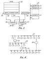
- Each network to which the bridge is joined may itself be a composite network including bridges.
- An example is shown in Figure 4, in which there are three networks 31, 32 and 33 interconnected by bridges 34, 35 and 36 each like the bridge 7.
- All three bridges must not be operative simultaneously, because otherwise multiple paths and looping would occur, resulting in conflicting versions of the same packet being propagated.
- the operative bridges must be selected to ensure that the combined network remains a tree. Selection takes place under operator control via the console of one of the bridges.
- Each half-bridge has its own network address, so that the operator may communicate with the bridges and set them to be operative in passing packets as required.
- the bridge 36 is set inoperative so that it passes no packets and the bridges 34 and 35 are set operative to pass packets.
- the bridge 34 will hold the addresses of the network 31 in one table and the addresses of the networks 32 and 33 in the other. It regards the combined networks 32 and 33 as the second network to which it is connected.
- the bridge 35 will hold the addresses of the network 33 in one table and of the combined network 31 and 32 in the other. So a packet from a station in the network 31 destined for a station of the network 33 will pass successively through the bridges 34 and 35. A packet from a station on the network 32 destined for a station of the network 31 will be passed through bridge 34, but will be blocked by bridge 35.
- the bridges have a maximum rate of throughput in either direction depending on the time needed to process a packet. If packets pass over either network at a greater rate the bridge will be unable to accept them and they will not be passed on to the other network. In that case, if the destination was in that other network, higher levels of the protocol will need to detect and recover from the failure.
- the protocols used in the two networks need not be the same. While in the described system only the minimum necessary contents of the packet are passed from one half- gateway to the other, if desired the frame check sequence may also be included in the contents of the packet passed from one half-bridge to the other. That allows an end-to-end check, including the correctness of the data transfer from one half-bridge to the other.
- the use of the bus 12 to interconnect the two half-bridges 7a and 7b imposes an upper limit on the separation between the points of the channels 4 and 6 that are joined.
- the half-bridges may be in separate cabinets each with its own bus, the half-bridges being joined by a transmission channel between the microcomputers 11 and 15.
- the method of address comparison described above is satisfactory provided the addresses are not too long.
- the address comparison can be carried out speedily using the 8086's string and search instruction.
- one current addressing scheme allots a globally unique 48-bit address to each participating device.
- the leading 24 bits designate the manufacturer and the trailing 24 bits are assigned by the manufacturer to distinguish uniquely between each of the items he manufactures.
- This scheme has the advantage for this invention that it ensures that addresses in a combined network will be unique.
- the method described above with reference to the drawings can advantageously be modified as follows.
- the address table 20 is split into two parts. One holds, in successive locations, the trailing 16 bits of each address. The other holds the remaining 32 bits of each address. Then, using the string word search instruction, the trailing 16 bits of the source or destination address are compared with the trailing 16 bits of each successive recorded address from the first part of the table until a match is found. Only at that point is it necessary to retrieve the initial 32 bits of the address from the second part of the table for a separate comparison to determine if that part also matches. It is found that most variation in addresses in a given network occurs in the final 16 bits, so this method proceeds very quickly with no retrieval of the initial 32 bits until a match is in fact found.
- microcomputer-based implementation described above could very well be replaced by special-purpose hardware.
Description
- This invention relates to the interconnection of communications networks.
- A communications network interconnects a number of stations to allow them to communicate with one another. It is known that such networks may themselves be interconnected by devices sometimes referred to as "bridges" or "gateways" to form a combined network in which station on either of the original networks may communicate with stations on the other network. These interconnection devices are of the store-and-forward type, and transmit messages received from one network on to the other.
- There is an especial need for such devices if the networks are local area networks using an access protocol based on carrier-sense multiple access with collision detection, (CSMA/CD) because the span of such networks is limited by the need to keep the maximum propagation delay within a prescribed limit. If two such networks of the maximum span are joined together by such an interconnection device a combined network may be formed whose total span exceeds the limit imposed on a single network.
- The use of devices for this purpose is described in "Ethernet: distributed packet switching for local computer networks" by R. M. Metcalfe and D. R. Boggs, Communications of the ACM, July 1976, pages 395 to 404. This paper also points out that the device may carry out address filtering by passing packets from one network to the other only if the destination station is located in the remote network. Address filtering in this manner requires the interconnection device to hold a table or record of the addresses of all stations in the remote network so that it can forward a packet only if its destination address matches one of those held. An advantage of address filtering is that it improves efficiency by reducing the packets transmitted in each of the individual networks.
- One object of the present invention is to provide an improved method of address filtering.
- The invention provides a method of transferring data from a first network to a second network, each network comprising a plurality of stations interconnected by transmission means, each station having an identifying address unique in the two networks, and data being transmitted in packets each defining a source address and a destination address, the method comprising:
- (a) maintaining an address table holding addresses exclusively of stations in the first network.
- (b) comparing the destination addresses of packets transmitted over the first network with the contents of said table and, if it is detected that the destination address of a packet is not held in said table, transmitting the packet on to the second network, and
- (c) comparing the source addresses of packets transmitted over the first network with the contents of said table and, if it is detected that the source address of a packet is not held in said table, entering that source address into said table.
- The address filtering is therefore carried out by blocking from the second network those packets passing over the first network that are detected as having a destination also on the first network. This is in distinction from the prior method described above, in which the address filtering is carried out by passing on to the second network those packets passing over the first network that are detected as having a destination on the second network. The method of the invention has the advantage that it will initialise itself automatically from a state in which the table is empty (for example at switch-on). Thus although packets addressed to a station on the first network that has not yet transmitted will be passed on to the second network, once the station has transmitted its address will be entered in the address table and all subsequent packets addressed to that station and originating from a station in the first network will be blocked from being passed to the second network. In most protocols, only a limited number of packets are sent to a station without a reply, so that number of packets that are passed on to the second network unnecessarily is correspondingly limited.
- The invention also provides apparatus for interconnecting first and second networks, the apparatus being arranged to receive data packets from the first network, each packet including a source address and a destination address, and to transfer selected ones of those packets to the second network, the apparatus comprising:
- (a) a table for holding a plurality of addresses,
- (b) means for comparing the destination address of a packet received from the first network with the contents of said table and, if no match is found, transferring that packet to the second network, and
- (c) means for comparing the source address of a packet received from the first network with the contents of said table and, if no match is found, entering that source address into said table.
- The invention further provides a combined network comprising a first and a second network each as specified above connected by apparatus according to the invention.
- Preferably the method or apparatus is symmetrical in also passing packets originating from a station of the second network on to the first network in the same manner as it passes them from the first network to the second.
- Networks including interconnection devices and in accordance with the invention will now be described in greater detail by way of example with reference to the accompanying drawings, in which
- Figure 1 is a diagram of a first network configuration,
- Figure 2 is a block diagram of an interconnection device,
- Figure 3 illustrates the structure of a half-bridge forming part of the interconnection device, and
- Figure 4 is a diagram of a second network configuration.
- Referring to Figure 1, the system includes two
local area networks network 1 consists of stations 3 (of which 3a to 3d are shown) connected to a common transmission channel 4 taking the form of a co-axial cable. The stations may for example be computer processors, terminals or peripherals. Thenetwork 2 consists of stations 5 (of which 5a to 5d are shown) connected to achannel 6 similar to thechannel 2. - The stations 3 of the
network 1 can communicate with one another over the channel 4 using the well-known CSMA/CD protocol. The stations transmit data in packets, each of which consists in sequence of a preamble, a destination address, a source address, user data and a frame check sequence. The source and destination addresses are the identifying addresses assigned respectively to the station transmitting the packet and the station for which it is intended. The stations 5 of thenetwork 2 can similarly communicate with one another over thechannel 6. - In order to allow stations on one network to communicate with those on the other, an interconnection device 7, which will be termed herein a bridge is connected between the two
channels 4 and 6. The bridge 7, in a manner to be described, ensures that any packet from one of the stations 3 of thenetwork 1 intended for a station 5 of thenetwork 2 will be transmitted onto thechannel 6 of thenetwork 2. It also acts similarly in the reverse direction. - For packets to be able to reach the right station it is necessary for the identifying address of each station to be unique in the combined network.
- Referring to Figure 2, the bridge 7 is constructed in two halves, 7a and 7b, associated respectively with the
networks half 7a is joined to the channel 4 by acable 8 ending at a transceiver 9 coupled to the channel 4. The inward terminal of thecable 8 is connected to a local-area-network controller 10. These components are commercially available for a number of protocols including CSMA/CD. For that protocol they are capable of carrying out the carrier sensing and collision detection it requires and transmitting packets when they determine that they are entitled to do so. When transmitting a packet they add the preamble at the start and append a frame check sequence at the end. When receiving a packet they normally recognise if the packet is addressed to the associated station and pass it on if so, stripped of the preamble and frame check sequence, provided the test on the frame check sequence is successful. They are also capable of being set to pass on all packets received that have a correct frame check sequence (once again stripped of preamble and frame check sequence). - Packets received by the controller 9 are passed to a
microcomputer 11 over a bus 12. The bus 12 may, for example, be according to the well-known Multibus specification. Attached to themicrocomputer 11 is a random-access memory (RAM) 13. - The bus 12 provides the link between the half-
bridge 7a and the half-bridge 7b. The latter is generally similar to the former, having a local-area-network controller 14 and amicrocomputer 15 to which is attached aRAM 16. A cable 17 connects thecontroller 14 in the half-bridge 7b to atransceiver 18 coupled to thecable 6. - An operator's
console 19 is connected to themicrocomputer 11 in the half-bridge 7a. - The operation of the half-
bridge 7a will now be described with reference also to Figure 3, which illustrates the operation diagrammatically. - The
microcomputer 11 holds a table 20 in theRAM 13 containing in operation addresses 21 of station 3 in thenetwork 1. Each packet transmitted by one of these stations passes over the channel 4 and is received by thecontroller 10, from which it is passed as explained to themicrocomputer 11. That stores the packet in a section of theRAM 13 arranged as a first-in first-out buffer (FIFO) 22. - As each packet comes to the head of the queue in the
FIFO 22, shown as apacket 23, it is processed as follows. Thesource address 24 anddestination address 25 of the packet are extracted and each compared with theaddresses 21 held in the table 20 until a match is found. For the comparisons theaddresses 21 are loaded successively into aregister 26 whose contents are compared with thesource address 24 anddestination address 25 atblocks destination address 25 matches the entry held in theregister 26 an indication shown as thearrow 29 is produced and comparisons with the destination addresses cease. If thesource address 24 matches the entry held in theregister 26 an indication shown as the arrow 30 is produced and comparisons with the source addresses cease. Theaddresses 21 held in the table 20 continue to be retrieved until either both source and destination addresses have been found in the table or all the entries have been retrieved. - If all the entries are retrieved without the destination address having been found, the
packet 23 is transferred to themicrocomputer 15 in the other half-bridge 7b, from where it is transferred to thecontroller 14. That transmits it over thenetwork 2. - If all the entries are retrieved without the source address having been found the source address is entered into the table 20 provided there is still free space for it.
- The comparisons of the source and destination addresses with an entry are in practice carried out using the arithmetic and logic unit of the
microprocessor 11 for both comparisons, one after the other. - Once the processing of the
packet 23 has been completed the next packet in theFIFO 22 is processed in the same way in its turn. - Thus packets from one station 3 of the
network 1 addressed to another station of that network, 3a to 3b say, will not be passed to thenetwork 2 provided the address of the destination 3b has already been entered in the table 20. That will occur the first time the station 3b sends a packet whether to a station in itsnetwork 1 or to a station in theother network 2. So until a station 3 has transmitted, the packets that are addressed to it from any other station 3 will be transmitted on to theother network 2. They will do no harm there, except using up some of its bandwidth. - The number of packets passed unnecessarily to the other network before the destination station is entered into the table 20 will normally be small, since most protocols require acknowledgement of packets. That ensures that a packet will be drawn from the destination (provided it is active) and will lead to its address being entered into the table 20. If the station is inactive other stations will not persevere in attempting to transmit to it. Alternatively, if desired, a station can be arranged to transmit a dummy packet as soon as it becomes active, in order to ensure it is entered in the table 20 at once.
- The other half-
bridge 7b behaves in a similar fashion and passes packets from thenetwork 2 on to thenetwork 1 provided its address table in theRAM 16, which holds addresses of stations on thenetwork 2, does not contain the packet's destination. - Since each half-bridge holds a table just of addresses in its associated network the comparisons are very simple and are carried out by separate means for the two directions. These means operate independently in carrying out the comparison, which take place in parallel for the two directions if packets from both networks are waiting to be processed. Simultaneous processing in this manner improves the throughput of the bridge 7.
- It will be realised that if the bridge 7 is brought into operation with the address table 20 in the half-
bridge 7a and its counterpart in the other half-bridge 7b both empty then the system will initialise itself automatically as packets start to pass and entries are made in the tables. It is also possible to enter addresses under operator control through theconsole 13. - Once the address tables are full, packets to any unrecorded station of the same network will be forwarded to the other network, again without harm except loss of bandwidth. If desired the tables may be periodically purged and re-initialised.
- The bridge 7 allows two networks each of the maximum allowable span to be interconnected to form a combined network that exceeds that maximum. It also reduces congestion in each component network compared to a simple repeater for all packets because it keeps from each component network some at least of the packets passing from one station to another on the other network. Often most communication will be between stations on the same network, so the number of packets passed over the bridge will be quite a small fraction of the total, with a corresponding benefit in reducing congestion.
- Packets with a broadcast destination address will be passed through the bridge since their destination does not correspond to any actual source that can have been entered into the address tables. Multicast addresses applying to stations in one network only may be entered by operator control into the appropriate table to ensure that packets with that address are kept to the network concerned.
- Each network to which the bridge is joined may itself be a composite network including bridges. An example is shown in Figure 4, in which there are three
networks bridges - All three bridges must not be operative simultaneously, because otherwise multiple paths and looping would occur, resulting in conflicting versions of the same packet being propagated. The operative bridges must be selected to ensure that the combined network remains a tree. Selection takes place under operator control via the console of one of the bridges. Each half-bridge has its own network address, so that the operator may communicate with the bridges and set them to be operative in passing packets as required.
- In the example of Figure 3, assume that the
bridge 36 is set inoperative so that it passes no packets and thebridges 34 and 35 are set operative to pass packets. Then, when initialised, thebridge 34 will hold the addresses of thenetwork 31 in one table and the addresses of thenetworks 32 and 33 in the other. It regards the combinednetworks 32 and 33 as the second network to which it is connected. Similarly the bridge 35 will hold the addresses of the network 33 in one table and of the combinednetwork network 31 destined for a station of the network 33 will pass successively through thebridges 34 and 35. A packet from a station on thenetwork 32 destined for a station of thenetwork 31 will be passed throughbridge 34, but will be blocked by bridge 35. - If now the bridge 35 is rendered inoperative and the
bridge 36 operative, packets for thenetwork 32 from the network 33 will reach it via thebridges bridge 34 nearer thenetwork 31 since it will now see the stations of the network 33 as belonging to a combined network connected to that half-bridge. The table in the half-bridge of thebridge 34 nearer thenetwork 32 is cleared, to remove the addresses of the network 33 which are no longer required. - The bridges have a maximum rate of throughput in either direction depending on the time needed to process a packet. If packets pass over either network at a greater rate the bridge will be unable to accept them and they will not be passed on to the other network. In that case, if the destination was in that other network, higher levels of the protocol will need to detect and recover from the failure.
- Various modifications may be made to the system described. Thus the protocols used in the two networks need not be the same. While in the described system only the minimum necessary contents of the packet are passed from one half- gateway to the other, if desired the frame check sequence may also be included in the contents of the packet passed from one half-bridge to the other. That allows an end-to-end check, including the correctness of the data transfer from one half-bridge to the other.
- The use of the bus 12 to interconnect the two half-
bridges channels 4 and 6 that are joined. To overcome this limitation, the half-bridges may be in separate cabinets each with its own bus, the half-bridges being joined by a transmission channel between themicrocomputers - The method of address comparison described above is satisfactory provided the addresses are not too long. For example, if the
microcomputers - The address table 20 is split into two parts. One holds, in successive locations, the trailing 16 bits of each address. The other holds the remaining 32 bits of each address. Then, using the string word search instruction, the trailing 16 bits of the source or destination address are compared with the trailing 16 bits of each successive recorded address from the first part of the table until a match is found. Only at that point is it necessary to retrieve the initial 32 bits of the address from the second part of the table for a separate comparison to determine if that part also matches. It is found that most variation in addresses in a given network occurs in the final 16 bits, so this method proceeds very quickly with no retrieval of the initial 32 bits until a match is in fact found.
- It will be realised that the microcomputer-based implementation described above could very well be replaced by special-purpose hardware.
Claims (9)
Applications Claiming Priority (2)
| Application Number | Priority Date | Filing Date | Title |
|---|---|---|---|
| GB848407102A GB8407102D0 (en) | 1984-03-19 | 1984-03-19 | Interconnection of communications networks |
| GB8407102 | 1984-03-19 |
Publications (3)
| Publication Number | Publication Date |
|---|---|
| EP0156542A2 EP0156542A2 (en) | 1985-10-02 |
| EP0156542A3 EP0156542A3 (en) | 1987-08-05 |
| EP0156542B1 true EP0156542B1 (en) | 1990-09-05 |
Family
ID=10558311
Family Applications (1)
| Application Number | Title | Priority Date | Filing Date |
|---|---|---|---|
| EP85301476A Expired - Lifetime EP0156542B1 (en) | 1984-03-19 | 1985-03-04 | Interconnection of communications networks |
Country Status (6)
| Country | Link |
|---|---|
| US (1) | US4627052A (en) |
| EP (1) | EP0156542B1 (en) |
| AU (1) | AU569380B2 (en) |
| DE (1) | DE3579485D1 (en) |
| GB (1) | GB8407102D0 (en) |
| ZA (1) | ZA851704B (en) |
Families Citing this family (159)
| Publication number | Priority date | Publication date | Assignee | Title |
|---|---|---|---|---|
| US4597078A (en) * | 1983-10-19 | 1986-06-24 | Digital Equipment Corporation | Bridge circuit for interconnecting networks |
| JPH0618374B2 (en) * | 1985-03-18 | 1994-03-09 | 株式会社日立製作所 | Data transmission method for multi-network system |
| GB8508740D0 (en) * | 1985-04-03 | 1985-05-09 | Plessey Co Plc | Switching arrangements |
| JPH0732401B2 (en) * | 1985-04-24 | 1995-04-10 | 株式会社日立製作所 | Transmission control method |
| US5182550A (en) * | 1985-05-31 | 1993-01-26 | Fujitsu Limited | Inter-network connection system |
| JPS61290835A (en) * | 1985-06-19 | 1986-12-20 | Hitachi Ltd | Loop communication system |
| EP0222584A3 (en) * | 1985-11-08 | 1989-07-19 | University Of Salford | A bridge for and a method for routeing signals between local area networks |
| JPH0648811B2 (en) * | 1986-04-04 | 1994-06-22 | 株式会社日立製作所 | Complex network data communication system |
| US4831620A (en) * | 1986-07-28 | 1989-05-16 | Bull Hn Information Systems Inc. | Controller for controlling multiple LAN types |
| US4750114A (en) * | 1986-07-28 | 1988-06-07 | Honeywell Bull Inc. | Local area network control block |
| US4715030A (en) * | 1986-08-04 | 1987-12-22 | General Electric Company | Local area network bridge |
| US4775864A (en) * | 1986-08-07 | 1988-10-04 | Standard Microsystems Corporation | Local area network with multiple node bus topology |
| US4740954A (en) * | 1986-12-31 | 1988-04-26 | Bell Communications Research, Inc. | Multicast routing algorithm |
| US4797881A (en) * | 1987-03-12 | 1989-01-10 | Sytek, Inc. | Bridge system for connecting networks |
| US4835673A (en) * | 1987-04-27 | 1989-05-30 | Ncr Corporation | Method and apparatus for sharing resources among multiple processing systems |
| US4866421A (en) * | 1987-06-18 | 1989-09-12 | Texas Instruments Incorporated | Communications circuit having an interface for external address decoding |
| US4887076A (en) * | 1987-10-16 | 1989-12-12 | Digital Equipment Corporation | Computer interconnect coupler for clusters of data processing devices |
| US4955018A (en) * | 1987-11-10 | 1990-09-04 | Echelon Systems Corporation | Protocol for network having plurality of intelligent cells |
| US4811337A (en) * | 1988-01-15 | 1989-03-07 | Vitalink Communications Corporation | Distributed load sharing |
| JPH01208934A (en) * | 1988-02-16 | 1989-08-22 | Sumitomo Electric Ind Ltd | Node equipment |
| US5018137A (en) * | 1988-06-27 | 1991-05-21 | Digital Equipment Corporation | Transparent load sharing for parallel networks |
| US5005120A (en) * | 1988-07-29 | 1991-04-02 | Lsi Logic Corporation | Compensating time delay in filtering signals of multi-dimensional reconvigurable array processors |
| NL8802132A (en) * | 1988-08-30 | 1990-03-16 | Philips Nv | LOCAL COMMUNICATION BUS SYSTEM, STATION FOR USE IN SUCH A SYSTEM, AND GATE CONNECTING ELEMENT FOR USE IN SUCH A SYSTEM, AND DEVICE CONTAINING SUCH A GATE CONNECTING ELEMENT. |
| US4922503A (en) * | 1988-10-28 | 1990-05-01 | Infotron Systems Corporation | Local area network bridge |
| US5383179A (en) * | 1988-12-15 | 1995-01-17 | Laboratoire Europeen De Recherches Electroniques Avancees | Message routing method in a system having several different transmission channels |
| US4897841A (en) * | 1989-01-11 | 1990-01-30 | Hughes Lan Systems, Inc. | System and method for bridging local area networks using concurrent broadband channels |
| US5036534A (en) * | 1989-01-31 | 1991-07-30 | Kenneth Gural | Intelligent telephone interface for automatic answering systems, and method of using |
| US4947390A (en) * | 1989-03-22 | 1990-08-07 | Hewlett-Packard Company | Method for data transfer through a bridge to a network requiring source route information |
| US5220562A (en) * | 1989-05-12 | 1993-06-15 | Hitachi, Ltd. | Bridge apparatus and a communication system between networks using the bridge apparatus |
| US5050165A (en) * | 1989-06-01 | 1991-09-17 | Seiko Instruments Inc. | Bridge circuit for interconnecting networks |
| US5860136A (en) * | 1989-06-16 | 1999-01-12 | Fenner; Peter R. | Method and apparatus for use of associated memory with large key spaces |
| US5058109A (en) * | 1989-06-28 | 1991-10-15 | Digital Equipment Corporation | Exclusionary network adapter apparatus and related method |
| CA2011934A1 (en) * | 1989-07-19 | 1991-01-19 | Theodore Heske, Iii | Method and apparatus for source routing bridging |
| US5475708A (en) * | 1989-09-25 | 1995-12-12 | Siemens Aktiengesellschaft | Circuit arrangement with at least one input and at least one output for forwarding an input signal that can be filtered, parallelized and digitized |
| JP2782683B2 (en) * | 1989-10-19 | 1998-08-06 | 三菱電機株式会社 | Communication method and node device in LAN |
| GB8927623D0 (en) * | 1989-12-06 | 1990-02-07 | Bicc Plc | Repeaters for secure local area networks |
| US5088090A (en) * | 1990-01-31 | 1992-02-11 | Rad Network Devices Ltd. | Routing system to interconnect local area networks |
| US5150360A (en) * | 1990-03-07 | 1992-09-22 | Digital Equipment Corporation | Utilization of redundant links in bridged networks |
| JPH03270532A (en) * | 1990-03-20 | 1991-12-02 | Fujitsu Ltd | Filtering control system |
| JP2904296B2 (en) * | 1990-03-30 | 1999-06-14 | マツダ株式会社 | Multiplex transmission equipment for vehicles |
| JPH07101886B2 (en) * | 1990-05-15 | 1995-11-01 | 三菱電機株式会社 | Bridge device |
| US5136580A (en) * | 1990-05-16 | 1992-08-04 | Microcom Systems, Inc. | Apparatus and method for learning and filtering destination and source addresses in a local area network system |
| US5111453A (en) * | 1990-05-18 | 1992-05-05 | Nynex Corporation | Apparatus and method for recognizing addresses of information packets |
| US5224205A (en) * | 1990-05-21 | 1993-06-29 | International Business Machines Corp. | Method of combining architecturally dissimilar computing networks into a single logical network |
| JP2703391B2 (en) * | 1990-06-18 | 1998-01-26 | 株式会社東芝 | Bridge device |
| US5122948A (en) * | 1990-06-28 | 1992-06-16 | Allen-Bradley Company, Inc. | Remote terminal industrial control communication system |
| US5309437A (en) * | 1990-06-29 | 1994-05-03 | Digital Equipment Corporation | Bridge-like internet protocol router |
| US5282198A (en) * | 1990-07-18 | 1994-01-25 | At&T Bell Laboratories | Initialization of data stations on a dual bus data subnetwork |
| FR2665040B1 (en) * | 1990-07-20 | 1994-08-05 | Thomson Csf | METHOD AND DEVICE FOR BRIDGING BETWEEN LOCAL AREA NETWORKS. |
| US5371868A (en) * | 1990-08-20 | 1994-12-06 | Digital Equipment Corporation | Method and apparatus for deriving addresses from stored address information for use in identifying devices during communication |
| US5481540A (en) * | 1990-08-24 | 1996-01-02 | At&T Corp. | FDDI bridge frame learning and filtering apparatus and method |
| JPH04107029A (en) * | 1990-08-27 | 1992-04-08 | Mitsubishi Electric Corp | System for connection between local area networks |
| US5166931A (en) * | 1990-09-04 | 1992-11-24 | At&T Bell Laboratories | Communications network dynamic addressing arrangement |
| US5404453A (en) * | 1990-09-13 | 1995-04-04 | Ncr Corporation | Terminals coupling system using bridge interfaces, located inside the host controller, with timer to determine start and end of transmission period |
| JP2644624B2 (en) * | 1990-11-30 | 1997-08-25 | 株式会社日立製作所 | Inter-network routing control method |
| US5956335A (en) * | 1991-01-25 | 1999-09-21 | Cabletron Systems, Inc. | Many to few group address translation through a network bridge |
| US5434864A (en) * | 1991-01-25 | 1995-07-18 | Digital Equipment Corporation | Encapsulation of an address within a forwarded frame in a computer communications system |
| US5285449A (en) * | 1991-04-03 | 1994-02-08 | International Business Machines Corporation | Protocol for hybrid local area networks |
| GB9107031D0 (en) * | 1991-04-04 | 1991-05-22 | Bicc Plc | Repeaters for digital data networks |
| US5341372A (en) * | 1991-04-10 | 1994-08-23 | California Institute Of Technology | Protocol for multiple node network |
| AU1584692A (en) * | 1991-04-15 | 1992-11-17 | Canai Computer And Network Architecture Inc. | Address caching network interface circuit for transparent bridge |
| US5321695A (en) * | 1991-05-01 | 1994-06-14 | Hewlett-Packard Company | Port arrival identification for computer network packets |
| WO1992021191A1 (en) * | 1991-05-24 | 1992-11-26 | Digital Equipment Corporation | Self-configuring data communication system and method |
| US5379292A (en) * | 1991-07-08 | 1995-01-03 | Naldec Corporation | Apparatus having priority order storages for recovery from failure of multiplex data transmission |
| US5471472A (en) * | 1991-07-30 | 1995-11-28 | Synernetics Inc. | Network multiplexer |
| US5327426A (en) * | 1991-09-27 | 1994-07-05 | Echelon Corporation | Method and apparatus for preventing unnecessary retransmission of messages in a networked messaging system |
| US5351243A (en) * | 1991-12-27 | 1994-09-27 | Digital Equipment Corporation | Monitor for packets on a communications network |
| US5537099A (en) * | 1992-04-16 | 1996-07-16 | Bay Networks, Inc. | Receiving port security in a network concentrator |
| ATE207679T1 (en) * | 1992-04-20 | 2001-11-15 | 3Com Corp | DEVICE FOR EXPANSION OF NETWORK MEANS TO REMOTE NETWORKS |
| JPH0619771A (en) * | 1992-04-20 | 1994-01-28 | Internatl Business Mach Corp <Ibm> | File management system of shared file by different kinds of clients |
| FR2690766B1 (en) * | 1992-04-30 | 1994-07-01 | Sgs Thomson Microelectronics | PROGRAMMABLE INTERFACE, ESPECIALLY FOR THE CONTROL OF DOMESTIC INSTALLATIONS. |
| US5432907A (en) * | 1992-05-12 | 1995-07-11 | Network Resources Corporation | Network hub with integrated bridge |
| US5742760A (en) * | 1992-05-12 | 1998-04-21 | Compaq Computer Corporation | Network packet switch using shared memory for repeating and bridging packets at media rate |
| US5412782A (en) | 1992-07-02 | 1995-05-02 | 3Com Corporation | Programmed I/O ethernet adapter with early interrupts for accelerating data transfer |
| JP3281043B2 (en) * | 1992-08-06 | 2002-05-13 | マツダ株式会社 | Multiplex transmission equipment |
| US5677910A (en) * | 1992-08-07 | 1997-10-14 | Plaintree Systems Inc. | High performance two-port transport LAN bridge |
| US5383187A (en) * | 1992-09-18 | 1995-01-17 | Hughes Aricraft Company | Adaptive protocol for packet communications network and method |
| US5649109A (en) * | 1992-10-22 | 1997-07-15 | Digital Equipment Corporation | Apparatus and method for maintaining forwarding information in a bridge or router using multiple free queues having associated free space sizes |
| JPH084273B2 (en) * | 1992-11-30 | 1996-01-17 | 日本電気株式会社 | Complex communication network |
| US5400331A (en) * | 1993-04-28 | 1995-03-21 | Allen-Bradley Company, Inc. | Communication network interface with screeners for incoming messages |
| DE69432524T2 (en) * | 1993-06-09 | 2004-04-01 | Btg International Inc. | METHOD AND DEVICE FOR A DIGITAL MULTIMEDIA COMMUNICATION SYSTEM |
| US6738357B1 (en) * | 1993-06-09 | 2004-05-18 | Btg International Inc. | Method and apparatus for multiple media digital communication system |
| GB2280339B (en) * | 1993-07-24 | 1997-10-22 | Digital Equipment Int | Wide area bridging path selection |
| US5598581A (en) * | 1993-08-06 | 1997-01-28 | Cisco Sytems, Inc. | Variable latency cut through bridge for forwarding packets in response to user's manual adjustment of variable latency threshold point while the bridge is operating |
| US5473607A (en) * | 1993-08-09 | 1995-12-05 | Grand Junction Networks, Inc. | Packet filtering for data networks |
| FR2709847B1 (en) * | 1993-09-07 | 1995-11-10 | Sagem | Data transmission network for at least two terminals. |
| US5381414A (en) * | 1993-11-05 | 1995-01-10 | Advanced Micro Devices, Inc. | Method and apparatus for determining if a data packet is addressed to a computer within a network |
| US5400326A (en) * | 1993-12-22 | 1995-03-21 | International Business Machines Corporation | Network bridge |
| DE4401465A1 (en) * | 1994-01-19 | 1995-08-10 | Siemens Ag | Communication module |
| US5617421A (en) * | 1994-06-17 | 1997-04-01 | Cisco Systems, Inc. | Extended domain computer network using standard links |
| US5615340A (en) * | 1994-07-21 | 1997-03-25 | Allied Telesyn Int'l Corp. | Network interfacing apparatus and method using repeater and cascade interface with scrambling |
| US5636245A (en) * | 1994-08-10 | 1997-06-03 | The Mitre Corporation | Location based selective distribution of generally broadcast information |
| US5566345A (en) * | 1994-08-31 | 1996-10-15 | Ostrowski; Carl L. | SCSI bus capacity expansion controller using gating circuits to arbitrate DMA requests from a plurality of disk drives |
| US5561669A (en) * | 1994-10-26 | 1996-10-01 | Cisco Systems, Inc. | Computer network switching system with expandable number of ports |
| US5884040A (en) * | 1995-01-11 | 1999-03-16 | Sony Corporation | Per-packet jamming in a multi-port bridge for a local area network |
| US5940597A (en) * | 1995-01-11 | 1999-08-17 | Sony Corporation | Method and apparatus for periodically updating entries in a content addressable memory |
| US6256313B1 (en) | 1995-01-11 | 2001-07-03 | Sony Corporation | Triplet architecture in a multi-port bridge for a local area network |
| US5764895A (en) * | 1995-01-11 | 1998-06-09 | Sony Corporation | Method and apparatus for directing data packets in a local area network device having a plurality of ports interconnected by a high-speed communication bus |
| US5857075A (en) * | 1995-01-11 | 1999-01-05 | Sony Corporation | Method and integrated circuit for high-bandwidth network server interfacing to a local area network |
| US5854898A (en) | 1995-02-24 | 1998-12-29 | Apple Computer, Inc. | System for automatically adding additional data stream to existing media connection between two end points upon exchange of notifying and confirmation messages therebetween |
| US5796738A (en) * | 1995-03-13 | 1998-08-18 | Compaq Computer Corporation | Multiport repeater with collision detection and jam signal generation |
| US5608726A (en) * | 1995-04-25 | 1997-03-04 | Cabletron Systems, Inc. | Network bridge with multicast forwarding table |
| JP3361915B2 (en) * | 1995-06-15 | 2003-01-07 | シャープ株式会社 | Wireless communication system |
| US5721874A (en) * | 1995-06-16 | 1998-02-24 | International Business Machines Corporation | Configurable cache with variable, dynamically addressable line sizes |
| US5742602A (en) * | 1995-07-12 | 1998-04-21 | Compaq Computer Corporation | Adaptive repeater system |
| FR2739510A1 (en) * | 1995-10-02 | 1997-04-04 | Canon Kk | Digital communication converter for frame transmission system |
| US5684800A (en) * | 1995-11-15 | 1997-11-04 | Cabletron Systems, Inc. | Method for establishing restricted broadcast groups in a switched network |
| US5764636A (en) * | 1996-03-28 | 1998-06-09 | Cisco Technology, Inc. | Color blocking logic mechanism for a high-performance network switch |
| TW301090B (en) * | 1996-08-14 | 1997-03-21 | Winbond Electronics Corp | Data storing and searching method of ethernet switch mean address table and device thereof |
| FR2753028B1 (en) * | 1996-08-30 | 1998-11-13 | Sextant Avionique | DEVICE FOR CONNECTING A PLURALITY OF ELECTRONIC EQUIPMENT TO AN ARINC 629 TYPE BUS |
| GB2320169B (en) * | 1996-11-29 | 2001-08-08 | 3Com Ireland | Network configuration |
| US6657999B1 (en) * | 1997-03-31 | 2003-12-02 | Texas Instruments Incorporated | Link layer gateway computer for interconnecting ethernet and 1394 networks |
| US6246680B1 (en) | 1997-06-30 | 2001-06-12 | Sun Microsystems, Inc. | Highly integrated multi-layer switch element architecture |
| US6044418A (en) * | 1997-06-30 | 2000-03-28 | Sun Microsystems, Inc. | Method and apparatus for dynamically resizing queues utilizing programmable partition pointers |
| US6081522A (en) * | 1997-06-30 | 2000-06-27 | Sun Microsystems, Inc. | System and method for a multi-layer network element |
| US6016310A (en) * | 1997-06-30 | 2000-01-18 | Sun Microsystems, Inc. | Trunking support in a high performance network device |
| US6049528A (en) * | 1997-06-30 | 2000-04-11 | Sun Microsystems, Inc. | Trunking ethernet-compatible networks |
| US6044087A (en) * | 1997-06-30 | 2000-03-28 | Sun Microsystems, Inc. | Interface for a highly integrated ethernet network element |
| US6088356A (en) * | 1997-06-30 | 2000-07-11 | Sun Microsystems, Inc. | System and method for a multi-layer network element |
| US6119196A (en) * | 1997-06-30 | 2000-09-12 | Sun Microsystems, Inc. | System having multiple arbitrating levels for arbitrating access to a shared memory by network ports operating at different data rates |
| US6081512A (en) * | 1997-06-30 | 2000-06-27 | Sun Microsystems, Inc. | Spanning tree support in a high performance network device |
| US6115378A (en) * | 1997-06-30 | 2000-09-05 | Sun Microsystems, Inc. | Multi-layer distributed network element |
| US6021132A (en) * | 1997-06-30 | 2000-02-01 | Sun Microsystems, Inc. | Shared memory management in a switched network element |
| US6094435A (en) * | 1997-06-30 | 2000-07-25 | Sun Microsystems, Inc. | System and method for a quality of service in a multi-layer network element |
| US6052738A (en) * | 1997-06-30 | 2000-04-18 | Sun Microsystems, Inc. | Method and apparatus in a packet routing switch for controlling access at different data rates to a shared memory |
| US6128666A (en) * | 1997-06-30 | 2000-10-03 | Sun Microsystems, Inc. | Distributed VLAN mechanism for packet field replacement in a multi-layered switched network element using a control field/signal for indicating modification of a packet with a database search engine |
| US6442168B1 (en) | 1997-09-17 | 2002-08-27 | Sony Corporation | High speed bus structure in a multi-port bridge for a local area network |
| US6301256B1 (en) | 1997-09-17 | 2001-10-09 | Sony Corporation | Selection technique for preventing a source port from becoming a destination port in a multi-port bridge for a local area network |
| US6816490B1 (en) | 1997-09-17 | 2004-11-09 | Sony Corporation | Statistical learning technique in a multi-port bridge for a local area network |
| US6308218B1 (en) | 1997-09-17 | 2001-10-23 | Sony Corporation | Address look-up mechanism in a multi-port bridge for a local area network |
| US6363067B1 (en) | 1997-09-17 | 2002-03-26 | Sony Corporation | Staged partitioned communication bus for a multi-port bridge for a local area network |
| US6157951A (en) * | 1997-09-17 | 2000-12-05 | Sony Corporation | Dual priority chains for data-communication ports in a multi-port bridge for a local area network |
| US6617879B1 (en) | 1997-09-17 | 2003-09-09 | Sony Corporation | Transparently partitioned communication bus for multi-port bridge for a local area network |
| US6594283B1 (en) | 1997-11-28 | 2003-07-15 | 3Com Corporation | Network communication device |
| US6157950A (en) * | 1997-12-05 | 2000-12-05 | Encanto Networks, Inc. | Methods and apparatus for interfacing a computer or small network to a wide area network such as the internet |
| WO1999045677A1 (en) * | 1998-03-06 | 1999-09-10 | 3Com Technologies | Network communication device |
| EP0945807A1 (en) * | 1998-03-27 | 1999-09-29 | Hewlett-Packard Company | Adress remapping for a bus |
| US6788681B1 (en) | 1999-03-16 | 2004-09-07 | Nortel Networks Limited | Virtual private networks and methods for their operation |
| US6937574B1 (en) | 1999-03-16 | 2005-08-30 | Nortel Networks Limited | Virtual private networks and methods for their operation |
| US6208647B1 (en) * | 1999-04-14 | 2001-03-27 | Verizon Laboratories Inc. | Multicast extension to data link layer protocols |
| US6320501B1 (en) | 1999-05-25 | 2001-11-20 | Pittway Corporation | Multiple sensor system for alarm determination with device-to-device communications |
| US6850529B1 (en) | 1999-10-06 | 2005-02-01 | Cisco Technology, Inc. | Layer 2 funnel in fan out network device |
| US7630398B2 (en) * | 2000-09-27 | 2009-12-08 | Intel Corporation | Subnet independent transparent bridge |
| US7389359B2 (en) | 2001-10-19 | 2008-06-17 | Foundry Networks, Inc. | Method and system for intelligently forwarding multicast packets |
| US7647422B2 (en) | 2001-11-06 | 2010-01-12 | Enterasys Networks, Inc. | VPN failure recovery |
| US8972589B2 (en) | 2002-03-01 | 2015-03-03 | Enterasys Networks, Inc. | Location-based access control in a data network |
| FR2852176B1 (en) * | 2003-03-04 | 2005-05-27 | DEVICE AND METHOD FOR INTERCONNECTING BETWEEN COMPUTER STATIONS COMMUNICATING THROUGH A SHARED MEDIUM | |
| US7580403B2 (en) | 2004-02-26 | 2009-08-25 | Enterasys Networks, Inc. | Status transmission system and method |
| US7945945B2 (en) | 2004-08-06 | 2011-05-17 | Enterasys Networks, Inc. | System and method for address block enhanced dynamic network policy management |
| US7347628B2 (en) | 2004-11-08 | 2008-03-25 | Enterasys Networks, Inc. | Optical interface identification system |
| US7437140B2 (en) * | 2005-01-21 | 2008-10-14 | Sony Corporation | Power line network bridge |
| US20060193328A1 (en) * | 2005-02-25 | 2006-08-31 | Ramana Rao | Network address filter including random access memory |
| US8086232B2 (en) | 2005-06-28 | 2011-12-27 | Enterasys Networks, Inc. | Time synchronized wireless method and operations |
| JP4869714B2 (en) * | 2006-01-16 | 2012-02-08 | 株式会社ソニー・コンピュータエンタテインメント | Information processing apparatus, signal transmission method, and bridge |
| US20070266127A1 (en) * | 2006-05-10 | 2007-11-15 | Richter Andrew H | Internal virtual local area network (lan) |
| ATE552675T1 (en) * | 2006-12-14 | 2012-04-15 | Bayerische Motoren Werke Ag | METHOD FOR NETWORKING CONTROL DEVICES OF A MOTOR VEHICLE, DATA BUS SYSTEM BASED THEREOF AND COMPUTER PROGRAM PRODUCT |
| US8324329B2 (en) * | 2007-08-07 | 2012-12-04 | Bridgestone Corporation | Process for producing functionalized polymers |
| US8625427B1 (en) | 2009-09-03 | 2014-01-07 | Brocade Communications Systems, Inc. | Multi-path switching with edge-to-edge flow control |
| WO2011150268A1 (en) | 2010-05-26 | 2011-12-01 | Wirefi Networks, Inc. | Multi-communications-media network device |
Family Cites Families (7)
| Publication number | Priority date | Publication date | Assignee | Title |
|---|---|---|---|---|
| US28811A (en) * | 1860-06-19 | Dulcimer | ||
| US3597549A (en) * | 1969-07-17 | 1971-08-03 | Bell Telephone Labor Inc | High speed data communication system |
| US3890471A (en) * | 1973-12-17 | 1975-06-17 | Bell Telephone Labor Inc | Loop data transmission arrangement employing an interloop communication terminal |
| US4287592A (en) * | 1979-05-23 | 1981-09-01 | Burroughs Corporation | Method and apparatus for interfacing stations in a multiloop communications system |
| US4284976A (en) * | 1979-06-07 | 1981-08-18 | Ford Motor Company | Interface between communication channel segments |
| US4556974A (en) * | 1983-10-07 | 1985-12-03 | Honeywell Inc. | Method for passing a token in a local-area network |
| US4597078A (en) * | 1983-10-19 | 1986-06-24 | Digital Equipment Corporation | Bridge circuit for interconnecting networks |
-
1984
- 1984-03-19 GB GB848407102A patent/GB8407102D0/en active Pending
-
1985
- 1985-03-04 DE DE8585301476T patent/DE3579485D1/en not_active Expired - Fee Related
- 1985-03-04 EP EP85301476A patent/EP0156542B1/en not_active Expired - Lifetime
- 1985-03-06 ZA ZA851704A patent/ZA851704B/en unknown
- 1985-03-11 US US06/710,547 patent/US4627052A/en not_active Expired - Lifetime
- 1985-03-18 AU AU40048/85A patent/AU569380B2/en not_active Ceased
Also Published As
| Publication number | Publication date |
|---|---|
| EP0156542A3 (en) | 1987-08-05 |
| ZA851704B (en) | 1985-10-30 |
| US4627052A (en) | 1986-12-02 |
| DE3579485D1 (en) | 1990-10-11 |
| EP0156542A2 (en) | 1985-10-02 |
| AU4004885A (en) | 1985-09-26 |
| GB8407102D0 (en) | 1984-04-26 |
| AU569380B2 (en) | 1988-01-28 |
Similar Documents
| Publication | Publication Date | Title |
|---|---|---|
| EP0156542B1 (en) | Interconnection of communications networks | |
| US5764634A (en) | Lan switch with zero latency | |
| US4750109A (en) | Method and system for expediting multi-packet messages in a computer network | |
| US4550402A (en) | Data communication system | |
| US4792947A (en) | Method of multi-address communication | |
| EP0537408B1 (en) | Routing in a network of bridge-connected LAN segments | |
| EP0597789B1 (en) | Multiport LAN bridge | |
| US5940597A (en) | Method and apparatus for periodically updating entries in a content addressable memory | |
| JPS60264142A (en) | Route designating method | |
| EP0632945A1 (en) | Packet reassembly method and apparatus | |
| EP0186320A1 (en) | Local area communication network | |
| EP0151837A1 (en) | System and method for communication between nodes of a closed loop local communication path | |
| US4701755A (en) | Data switching system | |
| EP0243563B1 (en) | Non coded information and companion data switching mechanism | |
| JPH04233846A (en) | Method and apparatus for data transmission | |
| EP0881801B1 (en) | Communication method and communication system | |
| JP3487879B2 (en) | Communication method and mechanism between packet mode support units in core of communication equipment | |
| JPS6069935A (en) | Data communication system | |
| JPH0832612A (en) | Ethernet switch | |
| JP3229096B2 (en) | Communication device and method, and computer system using them | |
| JPS6132629A (en) | Control method of multiple circuit communication | |
| JPS60190050A (en) | Transmission system | |
| JPH05336119A (en) | Mutual connection device between lans | |
| JPS6314534A (en) | Communication equipment using contention system | |
| JPS61127245A (en) | Communication network |
Legal Events
| Date | Code | Title | Description |
|---|---|---|---|
| PUAI | Public reference made under article 153(3) epc to a published international application that has entered the european phase |
Free format text: ORIGINAL CODE: 0009012 |
|
| AK | Designated contracting states |
Designated state(s): BE DE FR GB IT NL |
|
| PUAL | Search report despatched |
Free format text: ORIGINAL CODE: 0009013 |
|
| AK | Designated contracting states |
Kind code of ref document: A3 Designated state(s): BE DE FR GB IT NL |
|
| 17P | Request for examination filed |
Effective date: 19870703 |
|
| 17Q | First examination report despatched |
Effective date: 19890731 |
|
| ITF | It: translation for a ep patent filed |
Owner name: BARZANO' E ZANARDO ROMA S.P.A. |
|
| GRAA | (expected) grant |
Free format text: ORIGINAL CODE: 0009210 |
|
| AK | Designated contracting states |
Kind code of ref document: B1 Designated state(s): BE DE FR GB IT NL |
|
| REF | Corresponds to: |
Ref document number: 3579485 Country of ref document: DE Date of ref document: 19901011 |
|
| ET | Fr: translation filed | ||
| PLBE | No opposition filed within time limit |
Free format text: ORIGINAL CODE: 0009261 |
|
| STAA | Information on the status of an ep patent application or granted ep patent |
Free format text: STATUS: NO OPPOSITION FILED WITHIN TIME LIMIT |
|
| 26N | No opposition filed | ||
| ITTA | It: last paid annual fee | ||
| PGFP | Annual fee paid to national office [announced via postgrant information from national office to epo] |
Ref country code: NL Payment date: 19990224 Year of fee payment: 15 |
|
| PGFP | Annual fee paid to national office [announced via postgrant information from national office to epo] |
Ref country code: BE Payment date: 19990302 Year of fee payment: 15 |
|
| PG25 | Lapsed in a contracting state [announced via postgrant information from national office to epo] |
Ref country code: BE Free format text: LAPSE BECAUSE OF NON-PAYMENT OF DUE FEES Effective date: 20000331 |
|
| BERE | Be: lapsed |
Owner name: INTERNATIONAL COMPUTERS LTD Effective date: 20000331 |
|
| PG25 | Lapsed in a contracting state [announced via postgrant information from national office to epo] |
Ref country code: NL Free format text: LAPSE BECAUSE OF NON-PAYMENT OF DUE FEES Effective date: 20001001 |
|
| NLV4 | Nl: lapsed or anulled due to non-payment of the annual fee |
Effective date: 20001001 |
|
| PGFP | Annual fee paid to national office [announced via postgrant information from national office to epo] |
Ref country code: DE Payment date: 20010222 Year of fee payment: 17 |
|
| REG | Reference to a national code |
Ref country code: GB Ref legal event code: IF02 |
|
| PGFP | Annual fee paid to national office [announced via postgrant information from national office to epo] |
Ref country code: GB Payment date: 20020204 Year of fee payment: 18 |
|
| PGFP | Annual fee paid to national office [announced via postgrant information from national office to epo] |
Ref country code: FR Payment date: 20020211 Year of fee payment: 18 |
|
| PG25 | Lapsed in a contracting state [announced via postgrant information from national office to epo] |
Ref country code: DE Free format text: LAPSE BECAUSE OF NON-PAYMENT OF DUE FEES Effective date: 20021001 |
|
| PG25 | Lapsed in a contracting state [announced via postgrant information from national office to epo] |
Ref country code: GB Free format text: LAPSE BECAUSE OF NON-PAYMENT OF DUE FEES Effective date: 20030304 |
|
| GBPC | Gb: european patent ceased through non-payment of renewal fee | ||
| PG25 | Lapsed in a contracting state [announced via postgrant information from national office to epo] |
Ref country code: FR Free format text: LAPSE BECAUSE OF NON-PAYMENT OF DUE FEES Effective date: 20031127 |
|
| REG | Reference to a national code |
Ref country code: FR Ref legal event code: ST |