EP0160739A1 - Newspaper stream conveyor - Google Patents
Newspaper stream conveyor Download PDFInfo
- Publication number
- EP0160739A1 EP0160739A1 EP84113423A EP84113423A EP0160739A1 EP 0160739 A1 EP0160739 A1 EP 0160739A1 EP 84113423 A EP84113423 A EP 84113423A EP 84113423 A EP84113423 A EP 84113423A EP 0160739 A1 EP0160739 A1 EP 0160739A1
- Authority
- EP
- European Patent Office
- Prior art keywords
- support frame
- signatures
- conveyor system
- frame means
- belts
- Prior art date
- Legal status (The legal status is an assumption and is not a legal conclusion. Google has not performed a legal analysis and makes no representation as to the accuracy of the status listed.)
- Withdrawn
Links
Images


Classifications
-
- B—PERFORMING OPERATIONS; TRANSPORTING
- B65—CONVEYING; PACKING; STORING; HANDLING THIN OR FILAMENTARY MATERIAL
- B65H—HANDLING THIN OR FILAMENTARY MATERIAL, e.g. SHEETS, WEBS, CABLES
- B65H5/00—Feeding articles separated from piles; Feeding articles to machines
- B65H5/02—Feeding articles separated from piles; Feeding articles to machines by belts or chains, e.g. between belts or chains
- B65H5/021—Feeding articles separated from piles; Feeding articles to machines by belts or chains, e.g. between belts or chains by belts
- B65H5/023—Feeding articles separated from piles; Feeding articles to machines by belts or chains, e.g. between belts or chains by belts between a pair of belts forming a transport nip
-
- B—PERFORMING OPERATIONS; TRANSPORTING
- B65—CONVEYING; PACKING; STORING; HANDLING THIN OR FILAMENTARY MATERIAL
- B65H—HANDLING THIN OR FILAMENTARY MATERIAL, e.g. SHEETS, WEBS, CABLES
- B65H15/00—Overturning articles
- B65H15/008—Overturning articles employing belts
- B65H15/012—Overturning articles employing belts twisted belts
-
- B—PERFORMING OPERATIONS; TRANSPORTING
- B65—CONVEYING; PACKING; STORING; HANDLING THIN OR FILAMENTARY MATERIAL
- B65H—HANDLING THIN OR FILAMENTARY MATERIAL, e.g. SHEETS, WEBS, CABLES
- B65H29/00—Delivering or advancing articles from machines; Advancing articles to or into piles
- B65H29/12—Delivering or advancing articles from machines; Advancing articles to or into piles by means of the nip between two, or between two sets of, moving tapes or bands or rollers
-
- B—PERFORMING OPERATIONS; TRANSPORTING
- B65—CONVEYING; PACKING; STORING; HANDLING THIN OR FILAMENTARY MATERIAL
- B65H—HANDLING THIN OR FILAMENTARY MATERIAL, e.g. SHEETS, WEBS, CABLES
- B65H5/00—Feeding articles separated from piles; Feeding articles to machines
- B65H5/02—Feeding articles separated from piles; Feeding articles to machines by belts or chains, e.g. between belts or chains
- B65H5/021—Feeding articles separated from piles; Feeding articles to machines by belts or chains, e.g. between belts or chains by belts
- B65H5/025—Feeding articles separated from piles; Feeding articles to machines by belts or chains, e.g. between belts or chains by belts between belts and rotary means, e.g. rollers, drums, cylinders or balls, forming a transport nip
-
- B—PERFORMING OPERATIONS; TRANSPORTING
- B65—CONVEYING; PACKING; STORING; HANDLING THIN OR FILAMENTARY MATERIAL
- B65H—HANDLING THIN OR FILAMENTARY MATERIAL, e.g. SHEETS, WEBS, CABLES
- B65H5/00—Feeding articles separated from piles; Feeding articles to machines
- B65H5/36—Article guides or smoothers, e.g. movable in operation
- B65H5/38—Article guides or smoothers, e.g. movable in operation immovable in operation
-
- B—PERFORMING OPERATIONS; TRANSPORTING
- B65—CONVEYING; PACKING; STORING; HANDLING THIN OR FILAMENTARY MATERIAL
- B65H—HANDLING THIN OR FILAMENTARY MATERIAL, e.g. SHEETS, WEBS, CABLES
- B65H2301/00—Handling processes for sheets or webs
- B65H2301/30—Orientation, displacement, position of the handled material
- B65H2301/33—Modifying, selecting, changing orientation
- B65H2301/332—Turning, overturning
- B65H2301/3321—Turning, overturning kinetic therefor
- B65H2301/33212—Turning, overturning kinetic therefor about an axis parallel to the direction of displacement of material
-
- B—PERFORMING OPERATIONS; TRANSPORTING
- B65—CONVEYING; PACKING; STORING; HANDLING THIN OR FILAMENTARY MATERIAL
- B65H—HANDLING THIN OR FILAMENTARY MATERIAL, e.g. SHEETS, WEBS, CABLES
- B65H2404/00—Parts for transporting or guiding the handled material
- B65H2404/20—Belts
- B65H2404/26—Particular arrangement of belt, or belts
- B65H2404/261—Arrangement of belts, or belt(s) / roller(s) facing each other for forming a transport nip
-
- B—PERFORMING OPERATIONS; TRANSPORTING
- B65—CONVEYING; PACKING; STORING; HANDLING THIN OR FILAMENTARY MATERIAL
- B65H—HANDLING THIN OR FILAMENTARY MATERIAL, e.g. SHEETS, WEBS, CABLES
- B65H2701/00—Handled material; Storage means
- B65H2701/10—Handled articles or webs
- B65H2701/19—Specific article or web
- B65H2701/1932—Signatures, folded printed matter, newspapers or parts thereof and books
Definitions
- Another object of this invention is to provide a signature conveying apparatus having a pair of opposed belts positioned to between them grip the center area of the signature stream and convey the strea:n upwardly while simultaneously effecting reorientation thereof.
- An additional object is to provide a belt transfer and reorienting systems which reduces the localized pressure on the signatures and thereby minimizes the local damage caused by wire conveyor systems.
- a further object of this invention is to provide an improved signature conveying apparatus which utilized opposed endless belts to grip the signatures and which includes means to guide the lateral edges of the signatures as they are physically reoriented.
- the apparatus of this invention is for use in a conveyor system that is used for transporting newspaper signatures from the press to some other location where operations such as stacking are performed.
- the apparatus comprises basically a lower support frame means 10, and an upper support frame means 11.
- Each of the support frame means 10 and 11 is comprised of a pair of vertically extending side rails 12, and a plurality of horizontally extending intermediate rails 13, which function to join the side rails 12 together.
- the upper support frame means 11 is mounted on the upper end of the lower support frame means 10 and that it is turned at an angle of 90° with respect to the lower portion. For purposes of explanation only, while the present description is done using an angle of 90 between the two sections, it should be understood that any other angle of orientation could be selected if desired.
- the lower support frame means is mounted on top of an infeed device 15 which receives the newspaper signatures from a horizontal conveyor, not shown, and directs them upwardly toward the lower support frame means 10 by means of a pair of opposed endless belts 16 and 17.
- belt 16' is entrained about a plurality of rollers 18 which are journaled for rotation between the sides 19, only one of which is shown.
- a plurality of rollers 20 are journaled in siaes 19 to provide guiding means for the belt 17.
- the rollers 18 and 20 which are shown in Figure 1 as being furthest toward the right are placed a distance apart so that belts 16 and 17 converge toward the centermost roll 18 to define a throat 21 into which signatures are fed.
- signatures fed into throat 21 will be carried from the horizontal to the vertical direction toward the lower support frane means 10.
- Alos journaled between sides 19 of infeed device 15 is a rotating member that has a rollet 24 with a canning surface 25 that slopes outwardly with respect to the axis of rotation of roller 24-
- This roller 24 and camming surface 25 provide a belt biasing means that functions to retain the belts generally midway between side rails 12.
- Lower frame means 10 contains a plurality of horizontally extending belt guide rollers 31 and 32 which are journaled for rotation between side rails 12.
- Uppermost roller 32 is journaled in socket members 33, see Figure 2, that are carried on a threaded rod 34 so that by turning handle 35 roller 32 can be moved toward or away from opposed belts 16 and 17.
- Provision of this adjustable movement is important to successful operation of the present conveyor system because it enables the endless belts 16 and 17 to retain the signatures in the center of the support frame means 10 and 11 regardless of the thickness of the signatures that are being conveyed.
- Guide roller 30 is identical in construction to roller 24 and it provides a camming surface 36. By referring to Figure 2 it can be seen that camming surface 25 and camming surface 36 are oriented facing each other so that they cooperate with each other in centering belts 16 and 17.
- upper support frame means 11 is mounted on top of lower frame means at some preselected angle, here illustrated as being at 90°.
- the lowermost guide roll 40 journaled between side rails 12 of upper frame support means 11 has its axis of rotation turned at a 90 angle with respect to the axes of rotation of the various rolls journaled in frame means 10 and infeed section 15.
- Also carried by the upper frame means 11 are a pluralicy of guide, tensioning and drive rollers which coact with either one of the belts 16 and and 17 or both.
- Belt 16 is guided, tensioned and driven in the same manner as belt 17. Specifically it passes by a guide roller 60 journaled in side rails 12 over drive roll 61 driven by motor 62 through gear box 63 and over tensioning rollers 64, 65 mounted on arm 66 that is pivotally carried on side rail 12. This arm is biased like arm 47 by a tensioning spring 67 that is connected between its outer end (right as viewed in Figure 2) and mounting rod and bracket 68, the bracket being joined to side rail 12. Finally, belt 16 passes around guide roller 75 that is journaled on arm 76 mounted on side rail 12. One final guide roller is identified by nuneral 80 and this roll serves as a guide for both belts 16 and 17 before they begin to separate for their respective return runs.
- belt 17 moves downwardly from drive roll 55, around tensioning rollers 45, 46, guide rollers 41, 40, 32, camming guide roller 25, and finally around the lowermost guide rollers 20, prior to starting a return run upwardly.
- Belt 16 is guided in like fashion. Starting with drive roll 61 it moves downwardly around rollers 64, 65, 75, 31, 30 and finally around rollers 18 before starting its return run upwardly. Both belt 16 and belt 17 on the downward runs are twisted 90 in the manner shown in Figure 3 which illustrates the twist in belt 16.
- belts 16 and 17 After belts 16 and 17 have converged at throat 21 they come together so that signatures, such as that identified by numeral 85 will be trapped and held between them. As the belts travel upwardly together carrying the signatures, they are guided by the guide rolls 31 and 32 so that the signature assumes the position identified by numeral 86. As signatures continue on upwardly they are twisted with the belts so that they move from the orientation of station 86 to an intermediate position such as that shown at station 87. Continuing on, the signatures twist further until they have achieved the total preselected orientation and are positioned as shown at station 88.
- Each guide means comprises an elongated plate like element having terminal edges 105, 106 which are parallel to the axes of rotation of the adjacent guide rolls 40 and 32 respectively.
- edch guide element 90, 91 is formed with a twist that corresponds to the preselected angle that exists between the axes of rotation of the guide rollers in the lower and upper support frame means 10 and 11.
Abstract
An improved conveyor apparatus for changing the direction of flow of a stream of imbricated newspaper: signatures which utilizies continuous belts (16,17) that are in opposing contact through a part of their paths of travel, which belts are entrained about upper and lower guide rollers whose rotational axes angularly differ by some preselected angle to impart twist into the belts. Also, guide means (90,91) are provided for holding the edges of the signature in position during reorientation of the signatures from one direction to another.
Description
- It is well known that newspaper signatures are commonly taken from a press at a high rate of speed and transported appreciable distances in the form of an imbricated stream. Transport is usually effected by means a plurality of opposed coiled endless wire conveyor ribbons or opposed pairs of strips that are located at spaced positions across the width of the signatures.
- As mentioned earlier, signatures are usually moved considerable distances from the press, usually for counting, stacking and bundling in order that they can be shipped out. In the past it has been found that imbricated signatures must be moved vertically and also change directions in order to put them at the proper location and in the proper orientation for reception by a stacker, for example. While such wire conveyors have been effective, particularly on straight horizontal and vertical runs, they present problems in construction and operation when signatures must be physically reoriented for subsequent operations. However, the wire conveyors mark the product due to the localized pressure of the wires.
- It is therefore a principal object of this invention to provide a new apparatus for use in a newspaper conveyor system that can effectively transport signature copies vertically while simultaneously affecting reorientation thereof.
- Another object of this invention is to provide a signature conveying apparatus having a pair of opposed belts positioned to between them grip the center area of the signature stream and convey the strea:n upwardly while simultaneously effecting reorientation thereof.
- An additional object is to provide a belt transfer and reorienting systems which reduces the localized pressure on the signatures and thereby minimizes the local damage caused by wire conveyor systems.
- A further object of this invention is to provide an improved signature conveying apparatus which utilized opposed endless belts to grip the signatures and which includes means to guide the lateral edges of the signatures as they are physically reoriented.
- Other objects and advantages of this invention will be in part obvious and in part explained.by reference to the accompanying specification and drawings, in which:
-
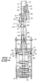
- Fig. 1 is a side elevation of the apparatus of this invention with part of the lower-supporting structure removed for clarity;
- Fig. 2 is a front elevation of the apparatus of Fig. 1, with the lower most imput feeder removed and part of the upper supporting structure removed for clarity;
- Fig. 3 is a schematic showing the manner in which the conveyor belts twist; and
- Fig. 4 is partly sectioned schematic illustrating the manner in which the belts grip.
- Description of the Preferred Embodiment
- Generally, the apparatus of this invention is for use in a conveyor system that is used for transporting newspaper signatures from the press to some other location where operations such as stacking are performed. The apparatus comprises basically a lower support frame means 10, and an upper support frame means 11. Each of the support frame means 10 and 11 is comprised of a pair of vertically extending
side rails 12, and a plurality of horizontally extendingintermediate rails 13, which function to join theside rails 12 together. It will be noted that the upper support frame means 11 is mounted on the upper end of the lower support frame means 10 and that it is turned at an angle of 90° with respect to the lower portion. For purposes of explanation only, while the present description is done using an angle of 90 between the two sections, it should be understood that any other angle of orientation could be selected if desired. Referring to Figure 1 of the drawings, it can be seen that the lower support frame means is mounted on top of an infeeddevice 15 which receives the newspaper signatures from a horizontal conveyor, not shown, and directs them upwardly toward the lower support frame means 10 by means of a pair of opposedendless belts - Within
infeed device 15, belt 16'is entrained about a plurality ofrollers 18 which are journaled for rotation between thesides 19, only one of which is shown. In similar fashion, a plurality ofrollers 20 are journaled insiaes 19 to provide guiding means for thebelt 17. Therollers belts centermost roll 18 to define athroat 21 into which signatures are fed. Withbelt 16 moving in the clockwise direction indicated byarrow 22 andbelt 17 in the anti-clockwise direction indicated byarrow 23, signatures fed intothroat 21 will be carried from the horizontal to the vertical direction toward the lower support frane means 10. Alos journaled betweensides 19 of infeeddevice 15 is a rotating member that has a rollet 24 with acanning surface 25 that slopes outwardly with respect to the axis of rotation of roller 24-Thisroller 24 andcamming surface 25 provide a belt biasing means that functions to retain the belts generally midway betweenside rails 12. - Lower frame means 10 contains a plurality of horizontally extending
belt guide rollers side rails 12.Uppermost roller 32 is journaled insocket members 33, see Figure 2, that are carried on a threadedrod 34 so that by turninghandle 35roller 32 can be moved toward or away fromopposed belts endless belts Guide roller 30 is identical in construction toroller 24 and it provides acamming surface 36. By referring to Figure 2 it can be seen thatcamming surface 25 andcamming surface 36 are oriented facing each other so that they cooperate with each other incentering belts - As mentioned earlier, upper support frame means 11 is mounted on top of lower frame means at some preselected angle, here illustrated as being at 90°. Thus, in this illustration the
lowermost guide roll 40 journaled betweenside rails 12 of upper frame support means 11 has its axis of rotation turned at a 90 angle with respect to the axes of rotation of the various rolls journaled in frame means 10 and infeedsection 15. Also carried by the upper frame means 11 are a pluralicy of guide, tensioning and drive rollers which coact with either one of thebelts - Specifically coacting with
belt 17 isguide roll 41 that is journaled onarm 42 fastened to anupper side rail 12.Tensioning rolls 45 and 46 are journaled onarm 47 that is pivotally attached toside tail 12.Arm 47 has its outer end (left end as viewed in Figure 2) biased upwardly by tensioningspring 50 that is connected toarm 47 at one end and toside rail 12 through mounting rod andbracket 51. The drive roll forbelt 17 is indicated by thenumeral 55.Roll 55 is driven bymotor 56 through thegear box 57. -
Belt 16 is guided, tensioned and driven in the same manner asbelt 17. Specifically it passes by aguide roller 60 journaled inside rails 12 overdrive roll 61 driven bymotor 62 throughgear box 63 and over tensioning rollers 64, 65 mounted onarm 66 that is pivotally carried onside rail 12. This arm is biased likearm 47 by atensioning spring 67 that is connected between its outer end (right as viewed in Figure 2) and mounting rod andbracket 68, the bracket being joined toside rail 12. Finally,belt 16 passes aroundguide roller 75 that is journaled onarm 76 mounted onside rail 12. One final guide roller is identified bynuneral 80 and this roll serves as a guide for bothbelts - Since the support frame means 10 and 11
side rails 12 and the various guide, arive, biasing and tensioning rollers are disposed or oriented as above described, it is apparent that thebelts belt 16 is shown as it exists between theupper guide roller 75 analower guide roller 31. - Turning to the general functioning or operation of the
belts belt 17 moves downwardly fromdrive roll 55, aroundtensioning rollers 45, 46,guide rollers camming guide roller 25, and finally around thelowermost guide rollers 20, prior to starting a return run upwardly. -
Belt 16 is guided in like fashion. Starting withdrive roll 61 it moves downwardly aroundrollers rollers 18 before starting its return run upwardly. Bothbelt 16 andbelt 17 on the downward runs are twisted 90 in the manner shown in Figure 3 which illustrates the twist inbelt 16. - After
belts throat 21 they come together so that signatures, such as that identified bynumeral 85 will be trapped and held between them. As the belts travel upwardly together carrying the signatures, they are guided by theguide rolls numeral 86. As signatures continue on upwardly they are twisted with the belts so that they move from the orientation ofstation 86 to an intermediate position such as that shown atstation 87. Continuing on, the signatures twist further until they have achieved the total preselected orientation and are positioned as shown atstation 88. - During reorientation of the signatures from
position 86 to thefinal position 88 it is essential that the lateral edges of the signatures be retained in the same relative positions with repect to each other throughout. This is effectively accomplished by means of a pair of guide means 90 and 91. Each guide means comprises an elongated plate like element havingterminal edges adjacent guide rolls edch guide element point 86 beyondroller 32 its lateral edges come into contact withguide elements elemencs - Although the present invention has been disolved in connection with the preferred embodiments, it is to be understood that modifications and variations may be resorted to without departing from the spirit and scope of the invention as those skilled in the art will readily understand. Such modifications and variations are considered to be within the purvieur and scope of the invention and the appendid claims.
Claims (6)
1. In a conveyor system for transporting newspaper signatures, an apparatus for turning the signatures through a preselected angle of twisc, said apparatus comprising:
(a) lower support frame means having vertically extending side rails and horizontally extending intermediate rails joining said side rails;
(b) upper support frame means having vertically extending side rails and horizontally extending intermediate rails joining said side rails, said upper support frame means being mounted on said lower support frame means in a position such that said intermediate rails of said lower and upper support frame means are disposed at a preselected angle with respect to each other;
(c) a plurality of rollers journaled on axes extending between said rails of said upper and lower support frame means;
(d) a pair of endless belts entrained about said rollers to provide a length where said belts are in opposing contact to hold the signatures between them and to twist the signatures throagh the preselected angle of turn; and
(e) guiae ne.ins secured to said upper and lower support frame menns and ectending therebetween to retain the lateiol edges of the signatures in the same relative relationship during the turn as they have during the remainder of transport through the conveyor system.
2. A conveyor system as defined in claim 1 wherein means is mounted on one of said frames in operative contact with each of said endless belts to continuously bias said belts toward the center of at least one of said entraining rollers.
3. A conveyor system as defined in claim 2 wherein said belt biasing means comprises a rotating member having a roller with a camming surface that slopes outwardly with respect to the axis of rotation of said rotating member.
4. A conveyor system as defined in claim 1 wherein said guide means comprises a pair of elongated plate-like elements of greater length than breadth, each said plate-like element having a lateral edge parallel to the axes of rotation of said rollers in said upper and lower support frame means.
5. A conveyor system as defined in claim wherein there is a guide roll adjacent to the upper side of sain guide means and a guide roll adjacent to lower end of saic guide means, the rotational axes of said rolls being disposed at a preselectea angle with respect to each other.
6. A conveyor system as defined in claim 5 wherein the lower of said rolls is mounted for adjustable movement toward and away from said opposed endless belts.
Applications Claiming Priority (2)
| Application Number | Priority Date | Filing Date | Title |
|---|---|---|---|
| US60504984A | 1984-04-30 | 1984-04-30 | |
| US605049 | 1990-10-29 |
Publications (1)
| Publication Number | Publication Date |
|---|---|
| EP0160739A1 true EP0160739A1 (en) | 1985-11-13 |
Family
ID=24422059
Family Applications (1)
| Application Number | Title | Priority Date | Filing Date |
|---|---|---|---|
| EP84113423A Withdrawn EP0160739A1 (en) | 1984-04-30 | 1984-11-07 | Newspaper stream conveyor |
Country Status (4)
| Country | Link |
|---|---|
| EP (1) | EP0160739A1 (en) |
| JP (1) | JPS60236963A (en) |
| AU (1) | AU3546184A (en) |
| BR (1) | BR8406311A (en) |
Cited By (4)
| Publication number | Priority date | Publication date | Assignee | Title |
|---|---|---|---|---|
| EP0281887A2 (en) * | 1987-03-09 | 1988-09-14 | Hagen Gämmerler | Transporting device for paper products, in particular overlapped products |
| DE3731151A1 (en) * | 1987-03-09 | 1988-09-22 | Hagen Gaemmerler | Conveying device for paper products, in particular in imbricated form |
| EP1170238A2 (en) * | 2000-05-18 | 2002-01-09 | NexPress Solutions LLC | Turning device |
| CN106219209A (en) * | 2016-08-29 | 2016-12-14 | 宁波永信精密管业有限公司 | The feeding device of sleeve member appearance detecting device |
Families Citing this family (2)
| Publication number | Priority date | Publication date | Assignee | Title |
|---|---|---|---|---|
| CN108639725B (en) * | 2018-07-03 | 2024-03-22 | 恒劢安全防护用品(南通)有限公司 | Hand mould strip conveyer belt of gloves gum dipping line |
| CN114515673B (en) * | 2022-02-22 | 2022-12-27 | 安徽工业大学 | Automatic gluing device for plastic straight joint |
Citations (2)
| Publication number | Priority date | Publication date | Assignee | Title |
|---|---|---|---|---|
| US3671035A (en) * | 1967-07-21 | 1972-06-20 | Ferag Ag | Conveyor apparatus |
| US4373712A (en) * | 1979-06-07 | 1983-02-15 | Gao Gesellschaft Fur Automation Und Organisation Mbh | Apparatus for transporting sheet material |
-
1984
- 1984-11-07 EP EP84113423A patent/EP0160739A1/en not_active Withdrawn
- 1984-11-15 AU AU35461/84A patent/AU3546184A/en not_active Abandoned
- 1984-12-06 JP JP59256629A patent/JPS60236963A/en active Pending
- 1984-12-10 BR BR8406311A patent/BR8406311A/en unknown
Patent Citations (2)
| Publication number | Priority date | Publication date | Assignee | Title |
|---|---|---|---|---|
| US3671035A (en) * | 1967-07-21 | 1972-06-20 | Ferag Ag | Conveyor apparatus |
| US4373712A (en) * | 1979-06-07 | 1983-02-15 | Gao Gesellschaft Fur Automation Und Organisation Mbh | Apparatus for transporting sheet material |
Cited By (14)
| Publication number | Priority date | Publication date | Assignee | Title |
|---|---|---|---|---|
| EP0281887A2 (en) * | 1987-03-09 | 1988-09-14 | Hagen Gämmerler | Transporting device for paper products, in particular overlapped products |
| DE3731151A1 (en) * | 1987-03-09 | 1988-09-22 | Hagen Gaemmerler | Conveying device for paper products, in particular in imbricated form |
| DE3744721A1 (en) * | 1987-03-09 | 1989-04-13 | Hagen Gaemmerler | Turning device for a stream of paper products, in particular in an imbricated formation |
| US4889333A (en) * | 1987-03-09 | 1989-12-26 | Gaemmerler Hagen | Conveying apparatus for paper products, in particular in stream form |
| EP0281887A3 (en) * | 1987-03-09 | 1990-07-25 | Hagen Gammerler | Transporting device for paper products, in particular overlapped products |
| EP0467417A2 (en) * | 1987-03-09 | 1992-01-22 | Hagen Gämmerler | Deviating device for a paper product stream, in particular in overlapped formation |
| EP0469636A2 (en) * | 1987-03-09 | 1992-02-05 | Hagen Gämmerler | Device for turning a product stream |
| EP0469636A3 (en) * | 1987-03-09 | 1992-08-05 | Hagen Gaemmerler | Device for turning a product stream |
| EP0467417A3 (en) * | 1987-03-09 | 1992-08-05 | Hagen Gaemmerler | Deviating device for a paper product stream, in particular in overlapped formation |
| EP1170238A2 (en) * | 2000-05-18 | 2002-01-09 | NexPress Solutions LLC | Turning device |
| EP1170238A3 (en) * | 2000-05-18 | 2003-01-15 | NexPress Solutions LLC | Turning device |
| US6626103B2 (en) | 2000-05-18 | 2003-09-30 | Nexpress Solutions Llc | Inverter |
| CN106219209A (en) * | 2016-08-29 | 2016-12-14 | 宁波永信精密管业有限公司 | The feeding device of sleeve member appearance detecting device |
| CN106219209B (en) * | 2016-08-29 | 2018-10-19 | 宁波永信精密管业有限公司 | The feeding device of sleeve member appearance detecting device |
Also Published As
| Publication number | Publication date |
|---|---|
| JPS60236963A (en) | 1985-11-25 |
| BR8406311A (en) | 1986-06-24 |
| AU3546184A (en) | 1985-11-07 |
Similar Documents
| Publication | Publication Date | Title |
|---|---|---|
| US4603800A (en) | Apparatus for transporting sheets of packaging material | |
| US4705157A (en) | Article turning assembly | |
| US4063632A (en) | Swingable arcuate guide for selectively orienting articles | |
| US5112041A (en) | Process and apparatus for transporting printing products arriving in imbricated formation | |
| US5474168A (en) | Stacking apparatus and method that reorients product units along a generally helical line while being conveyed from a loading station to an unloading station | |
| US6398010B1 (en) | Device for depositing flat objects, conveyed individually in succession, on a forwarding conveyor in shingle formation | |
| EP0160739A1 (en) | Newspaper stream conveyor | |
| US4204672A (en) | Device for conveying sheets within a sheet processing machine | |
| JPH0339943B2 (en) | ||
| US3966188A (en) | Label transport | |
| CA1065787A (en) | Board grouping apparatus | |
| US6152292A (en) | Device for automatic elimination of scraps in the manufacture of rolls of paper | |
| FI75527B (en) | TRANSPORT OR TRAFFIC TRUCKS. | |
| US4745727A (en) | Device serving to fashion carrying handles for attachment to sheet wrapping material, and a handle obtained with such a device | |
| US5667214A (en) | Envelope turning and aligning apparatus | |
| EP1409347B1 (en) | Method and apparatus for wrapping printed matters | |
| US4736940A (en) | Apparatus for aligning an opening of a sack | |
| US5178383A (en) | Method of separating sheets | |
| US5025609A (en) | Sheet separator device | |
| CA2010426C (en) | Process and apparatus for the temporary storage of multi-sheeted, folded printing products, such as newspapers, periodicals and parts thereof | |
| JPH06316359A (en) | Device to accumulate sheet paper or similar thing into piled body | |
| US4925006A (en) | Conveyor apparatus having means for a shock-free article acceleration | |
| JP4013193B2 (en) | Article alignment equipment | |
| JP2698542B2 (en) | Form accumulation processing device and form accumulation method | |
| US4641829A (en) | Screen printing machine having a stationary printing table |
Legal Events
| Date | Code | Title | Description |
|---|---|---|---|
| PUAI | Public reference made under article 153(3) epc to a published international application that has entered the european phase |
Free format text: ORIGINAL CODE: 0009012 |
|
| AK | Designated contracting states |
Designated state(s): BE CH DE FR GB IT LI NL SE |
|
| STAA | Information on the status of an ep patent application or granted ep patent |
Free format text: STATUS: THE APPLICATION IS DEEMED TO BE WITHDRAWN |
|
| 18D | Application deemed to be withdrawn |
Effective date: 19860714 |
|
| RIN1 | Information on inventor provided before grant (corrected) |
Inventor name: SCHWANKERT, DAVID C. Inventor name: ECKERSON, ROBERT D. |