EP0163248A2 - Spinning manifold for melt-spinning synthetic fibres - Google Patents
Spinning manifold for melt-spinning synthetic fibres Download PDFInfo
- Publication number
- EP0163248A2 EP0163248A2 EP85106256A EP85106256A EP0163248A2 EP 0163248 A2 EP0163248 A2 EP 0163248A2 EP 85106256 A EP85106256 A EP 85106256A EP 85106256 A EP85106256 A EP 85106256A EP 0163248 A2 EP0163248 A2 EP 0163248A2
- Authority
- EP
- European Patent Office
- Prior art keywords
- heating jacket
- nozzle
- melt
- pump block
- spinning
- Prior art date
- Legal status (The legal status is an assumption and is not a legal conclusion. Google has not performed a legal analysis and makes no representation as to the accuracy of the status listed.)
- Granted
Links
Images


Classifications
-
- D—TEXTILES; PAPER
- D01—NATURAL OR MAN-MADE THREADS OR FIBRES; SPINNING
- D01D—MECHANICAL METHODS OR APPARATUS IN THE MANUFACTURE OF ARTIFICIAL FILAMENTS, THREADS, FIBRES, BRISTLES OR RIBBONS
- D01D4/00—Spinnerette packs; Cleaning thereof
- D01D4/06—Distributing spinning solution or melt to spinning nozzles
-
- D—TEXTILES; PAPER
- D01—NATURAL OR MAN-MADE THREADS OR FIBRES; SPINNING
- D01D—MECHANICAL METHODS OR APPARATUS IN THE MANUFACTURE OF ARTIFICIAL FILAMENTS, THREADS, FIBRES, BRISTLES OR RIBBONS
- D01D4/00—Spinnerette packs; Cleaning thereof
Definitions
- the invention relates to a spinning beam for extrusion, in particular melt spinning synthetic threads according to the preamble of claim 1.
- Such a spinning beam (compare DE-AS 19 08 207) consists of a double-walled heating jacket, which is designed to hold a particularly vaporous heating medium as a pressure vessel and in its interior open chambers with plane-parallel machined heating surfaces for receiving and heat-conducting connection of melt-carrying components, such as pump blocks, metering pumps and optionally heat-conducting blocks.
- the heating jacket of the spinning beam is housed in a housing and surrounded by thermal insulation.
- melt-carrying components lie on a double-walled heating plate, which can be flat or L-shaped or U-shaped in cross-section and is supplemented by applied, heat-conducting fillers to form a closed hollow beam. All melt-carrying components can only be used from above, for which the insulating pieces and the corresponding fillers have to be removed. Between the insulating bodies and the packing may occur due to manufacturing tolerances and different thermal expansions, more or less there are wide gaps through which as a result of K amine effectively uncontrolled heat can flow. This can lead to different heating of the melt at the different spinning positions of the spinning beam.
- the object is achieved by a spinning beam with the features specified in the characterizing part of claim 1.
- the specified solution offers the advantages of a very uniform and inexpensive heating of all melt-carrying components and avoids vertical separating joints within the parts of the heating jacket and the thermal insulation.
- the chamber formed between the outer, horizontal U-legs of the heating jacket, which is U-shaped in cross section, for receiving the melt-carrying components is closed off from the nozzle shafts built into the heating jacket, and the chamber is sealed from the side (reduction of the overall height ) or accessible from above, while the nozzle pots with the pre-assembled nozzle packages are installed through the nozzle shafts in the heating jacket.
- a working platform above the spinning beam can be omitted if this is desirable.
- a connecting plug in particular with an external thread or bayonet lock for connecting the nozzle pot receiving the nozzle packet, is pressure-tightly connected to the pump block, in particular is screwed to or connected to the pump block forms a component.
- the development according to claim 3 has the further advantage that the V.e-rrivsstopfen for connecting the nozzle pot does not have to be dismantled within the nozzle shaft if the pump block is to be removed. Rather, the pump block with the connecting plug can be assembled and / or disassembled as a unit through the shaft formed between the U-legs of the heating jacket.
- the heating jacket from two mechanically independent heating chambers, which complement each other in a U-shaped cross section and have a flat, continuous separating surface along one of the horizontal U-legs.
- Such a construction offers the advantage that the melt-carrying components are clearly placed on the lower U-leg of the spinning beam and then the two mechanically independent heating chambers when the spinning beam is installed can be clamped together and with the melt-carrying components, whereby essentially all air gaps between the heat transfer surfaces can be avoided.
- the double-walled heating jacket has a substantially circular cross-section circumscribing the ends of the chamber and the nozzle shaft.
- Such a design of the outer wall of the heating jacket has the advantage that it manages with a very small wall thickness.
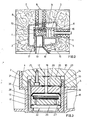
- the spinning beam 1 shows the top view of the spinning beam 1 shown in cross section in FIG. 2, which has a plurality of nozzle arrangements arranged in series one behind the other for melt spinning synthetic threads made of thermoplastic polymers.
- the spinning beam 1 essentially consists of a double-walled heating jacket 2, which, in particular, acts as a pressure container for receiving the heat transfer medium vaporous diphenyls, is formed and receives the melt-carrying components in a chamber 6 delimited by plane-parallel machined heat transfer surfaces 3, 4, 5.
- the heating jacket 2 is enclosed in its entirety to reduce heat losses by a sheet metal housing 7, which is stuffed with mineral wool 8 or another suitable insulating material.
- the insulating materials are present as insulating bodies pressed into geometrically simple shapes, which can be removed from the sheet metal housing at the appropriate point by means of closable cutouts.
- a heated melt feed line 9 which is connected to a melting device, such as an extruder or discharge pump, leads through the sheet metal housing 7 from above.
- the melt feed line 9 leads through the double-walled heating jacket 2 and is connected to a cuboid-shaped distributor block, from which branch ducts lead in a vertical direction to the pump blocks 10 lying next to one another.
- a branch leads from this channel to the suction side of the melt metering pump 11 attached to the pump block 10 and at least one pressure channel to an outlet opening 12 (FIG. 3), to which a nozzle pot 13 with a nozzle packet 22 is connected in a pressure-tight manner.
- the heating jacket 2 of the spinning beam 1 is double-walled over its entire length and U-shaped in cross-section, the two U-legs 14 and 15 of the heating jacket 2 being aligned horizontally or vertically (FIG. 7).
- a chamber 6 or one extends over the entire length of the heating jacket 2 extending shaft formed, which is limited at its ends to avoid heat loss by heat-conducting blocks in the form of fillers 16.
- the melt-carrying components such as pump blocks 10, melt metering pumps 11 and the melt distributor block, are accommodated in the chamber 6.
- the melt-carrying components rest on the heat transfer surface 5 of the U-leg 15 facing the chamber 6 and are pressed on by additional tension or compression screws in order to improve the heat transfer to the components to be heated.
- a plurality of nozzle shafts 17, ie, according to FIG. 1, for example, two nozzle shafts 17 per pump block 10, for the installation of the nozzle pots 13 in the heating jacket 2 are welded pressure-tight, starting from the chamber 6 vertically downwards, whereby the lower U-leg 15 of the double-walled heating jacket 2 is penetrated.
- the adjacent nozzle shafts 17 can preferably form a common component which extends over the entire length of the spinning beam 1 and is welded into the heating jacket 2.
- a spinning shaft extension 18 is connected to the vertical nozzle shafts 17 in order to make the nozzle pots 13 more accessible for assembly work.
- the blowing chutes leading downward, but not shown, are flanged to the ⁇ spinning chute extension 18.
- the spinning shaft extension 18 also serves to support and to fasten the spinning beam 1 to a carrier of a work platform or the like.
- the pump block 10 has a preferably circular cylindrical recess 23 on its underside in the region of each nozzle shaft 17.
- a connecting plug 20 with a central melt channel 19 is inserted in this recess 23 in a pressure-tight manner by means of fastening screws 25 distributed around the circumference.
- the melt channel 19 is aligned with the outlet opening 12 of the pump outlet channel in the pump block 10.
- the downward-facing end face 24 of the connecting plug 20 behind the bearing surface of the pump block 10 on the heat transfer surface-5 of the lower U-leg of the heating jacket 2 somewhat jumps back.
- the pump block 10 can be removed and installed from the chamber 6 and no assembly work on the connecting plug 20 can be carried out from the nozzle shaft 17.
- the connecting plug 20 has a thread 21 on its circumference, which can be of multiple threads, or a bayonet lock for simple and quick removal of the nozzle pots 13.
- the nozzle pack 22 accommodated in the nozzle pot 13 consists, in a known manner, of a nozzle plate 26, into which a plurality of nozzle bores are made, one Melt distributor plate 27, in which a filter 28 is arranged in a circular cylindrical recess and from a seal 29 which seals the nozzle packet 22 against the connecting plug 20 by the force of a differential piston 33 under melt pressure.
- the nozzle pack 22 is sealed between the differential piston 33 and the melt distributor plate 27 by a metal membrane 34 which is supported on the melt distributor plate 27.
- the attachment of the nozzle pot 13 to the connecting plug 20 means that the heating jacket 2 no longer has to absorb tensile forces resulting from the melt pressure. This is of great advantage for the dimensioning of the wall thickness of this critical component (pressure vessel).
- Fig. 4 shows the cross section of a spinning beam 1, in which, however, the radially outward-facing outer wall of the heating jacket 2 is essentially circularly curved and consists, for example, of tubular sections cut open in the longitudinal direction in a suitable manner. It has a length that extends to the ends of the horizontal chamber 6 for accommodating the melt-carrying components and the ends of the nozzle shafts 17 which are guided downward through the heating chamber 2.
- the solution shown is simple in terms of production technology and advantageous in terms of the stress caused by the pressure of the heat transfer medium.
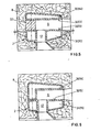
- FIG. 5 and 6 show a schematic representation of cross sections of spinning beams corresponding to FIG. 2, but in which the heating jacket 2 is composed of two mechanically independent heating chambers 30 and 31, which have two separating surfaces 32 in FIG. 5 and one in FIG. 6 .
- the lower U-leg 15 of the heating jacket 2 has a flat separating surface 32, on which all melt-carrying components are placed and fastened when the spinning beam 1 is assembled.
- the heating jacket 2 is then only supplemented by the U-leg 14, which is placed and braced from above and which has an L-shaped cross section according to FIG. 6.
- a corresponding U-shaped cross section is achieved by a heat-conducting block 37 which extends over the length of the heating jacket 2 and which is clamped to the heating chambers 30 and 31 having planar parting surfaces 32 while simultaneously clamping the melt-carrying components.
- All of the exemplary embodiments shown in FIGS. 1 to 6 have the horizontally arranged chamber 6 between the outer U-legs 14, 15 of the heating jacket 2 for the lateral installation of the pump blocks 10 and the melt metering pumps 1] as well as the nozzle shafts installed in the lower U-legs 15 17 as a common constructive feature.
- heating chambers 30, 31 of both U-legs 14, 15 are connected to one another and structural details regarding the heating of the heating jacket 2, which are not essential for understanding the invention, have been omitted in the drawing for the sake of simplicity .
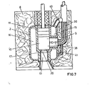
- FIG. 7 finally shows the cross section of a spinning beam 1 according to the design principle on which this invention is based, but in which the U-legs 14, 15 of the heating jacket 2 are oriented vertically and the nozzle shafts 17 starting from the pump shaft 6 vertically downward into the double-walled heating jacket 2 are pressure-tight installed, especially welded.
- the pump block 10 and the melt metering pump 11 are installed in the pump shaft 6 from above. Nevertheless, the nozzle shafts 17 are sealed off at their upper end by the pump block 10, which extends essentially over the entire length of the spinning beam 1, so that air circulation due to a chimney effect is prevented.
- the pump block 10 also has a corresponding number of connecting plugs 20 on the melt outlet side, which can form a common component with the pump block 10 or are non-positively and pressure-tightly connected to the latter.
- the nozzle pots 13 are screwed onto the connecting plugs 20, so that the melt forces are absorbed exclusively by the pump block 10 and the nozzle pots 13 and do not stress the heating jacket 2 and the nozzle shaft 17.
- the polymer melt is supplied here through the melt feed 9 arranged laterally, which opens into a valve module 38 or the like, which is connected to the pump block 10 and is guided through the vertical U-leg 15 of the double-walled heating jacket 2.
- the annular space 39 around the melt feed line is connected to the heating chambers of the heating jacket by branch lines 40, 41.
- the line 41 can, for example, discharge the condensate accumulating in front of the valve module 38.
- the invention also offers the particular advantage that the nozzle package, i.e. in particular, the nozzle plate, distribution elements and filters can be inserted into the nozzle pot before being attached to the heating box. To maintain a spinning station, it is then only necessary to remove the nozzle pot which is in operation and to insert a fresh nozzle pot. Compared to the previously known spinning heads, this saves in particular the laborious overhead work of individually removing and reinstalling the individual parts of the spinning head. It is avoided that the forces exerted by the melt pressure have to be absorbed by the spinning beam or heating jacket to such an extent that the stability suffers as a result.
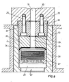
- Fig. 8 explains the attachment of the nozzle cup.
- the spinning beam carries the pump block 10, which is accommodated in a heating box 2, or a melt line module with the melt line 19, via which the spinning station is supplied.
- the pump block 10 (or fusible link module) has a suitable recess into which the connecting plug 20 is inserted.
- An annular seal is inserted between it (20) and the pump block 10, the bearing surface of which essentially determines the level of the forces to be exerted by the fastening screws in order to achieve a tight and pressure-resistant connection.
- the inner diameter of the ring seal also corresponds to that of the melt line 19.
- a thread 21 is incorporated in the connecting plug 20, which can be designed as a multi-start, self-locking and thus quickly tightened thread or as a bayonet connection.
- the nozzle pot 13 receiving the nozzle packet 22 is correspondingly on its upper part has a matching counterpart on the inside.
- the inner diameter of the nozzle pot is substantially equal to the outer diameter of the connecting plug.
- nozzle pot 13 sits the nozzle pack, which consists of the spinneret 26, the pressure or distributor plate 27 with the melt bores, the melt chamber lying between the two and the filter pack 28 inserted into the pot-shaped upper part of the pressure plate 27.
- a piston 33 which closes off the nozzle packet, sits above the pot with the filter pack 28 and is sealed off from the pot by the plate-shaped membrane 34.
- a further ring seal 29 is provided between the piston 33 and the connecting plug 20, to which the above-mentioned seal also applies.
- the thread 21 should be a bayonet lock designed as a three-start thread, which has axially extending recesses extending to the bottom of the thread in respective partial areas of its circumference, which are the same as the thread regions, namely three such recesses should be present evenly distributed. It is understood that the plug 20 and pot 13 fit together.
- the nozzle cup 13 with the nozzle pack and the plate membrane 34 and the piston 33 is then inserted into the bayonet thread of the connecting plug 20 and then only slightly tightened by turning it by about 60 °.
- the high contact pressure required for sealing is generated by the melt pressure itself, which is applied via the plate membrane 34 acts on the piston 33 and compresses the seal 29.
- the piston 33 is sealed by a plate membrane 34 with respect to the interior of the nozzle cup, in which it can be axially displaced.
- the object of the invention is then achieved that the nozzle change process is drastically simplified and accelerated and also that the force resulting from the high melt pressure and introduced into the suspension of the nozzle construction is significantly reduced compared to the effective in the nozzle pack.
- This can improve the heating box.
- the heating box is used to hold a liquid and / or vaporous, pressurized heating medium and to transfer heat to melt-carrying parts, in particular the pump block. It is a critical component in terms of its strength and ductility. According to the invention, it is largely freed from its function of absorbing the force of the melt pressure, and although it can be designed to be weaker, it can nevertheless be improved in its stiffness, which is particularly important for heat transfer to all melt-carrying parts and in particular the pump block.
Abstract
Description
Die Erfindung bezieht sich auf einen Spinnbalken zum Strangpressen, insbesondere Schmelzspinnen synthetischer Fäden nach dem Oberbegriff des Anspruch 1.The invention relates to a spinning beam for extrusion, in particular melt spinning synthetic threads according to the preamble of claim 1.
Ein derartiger Spinnbalken (vergleiche DE-AS 19 08 207), besteht aus einem doppelwandigen Heizmantel, der zur Aufnahme eines insbesondere dampfförmigen Heizmittels als Druckbehälter ausgebildet ist und in seinem Inneren nach oben offene Kammern mit planparallel bearbeiteten Heizflächen zur Aufnahme und wärmeleitenden Verbindung schmelzeführender Bauteile, wie Pumpenblöcke, Dosierpumpen sowie gegebenenfalls Wärmeleitblöcke aufweist. Der Heizmantel des Spinnbalkens ist in einem Gehäuse untergebracht und von einer Wärmeisolierung umgeben.Such a spinning beam (compare DE-AS 19 08 207) consists of a double-walled heating jacket, which is designed to hold a particularly vaporous heating medium as a pressure vessel and in its interior open chambers with plane-parallel machined heating surfaces for receiving and heat-conducting connection of melt-carrying components, such as pump blocks, metering pumps and optionally heat-conducting blocks. The heating jacket of the spinning beam is housed in a housing and surrounded by thermal insulation.
Bei dem bekannten Heizkasten liegen die schmelzeführenden Bauteile auf einer doppelwandigen Heizplatte, die eben oder im Querschnitt L- oder U-förmig ausgebildet sein kann und durch aufgelegte, wärmeleitende Füllkörper zu einem geschlossenen Hohlbalken ergänzt ist. Alle schmelzeführenden Bauteile können nur von oben eingesetzt werden, wozu die Isolierstücke und die entsprechenden Füllkörper ausgebaut werden müssen. Zwischen den Isolierkörpern und den Füllkörpern können aufgrund von Fertigungstoleranzen und unterschiedlichen Wärmedehnungen mehr oder weniger breite Spalte vorliegen, durch welche infolge einer Kaminwirkung unkontrolliert Wärme abfließen kann. Dies kann zu einer unterschiedlichen Beheizung der Schmelze an den verschiedenen Spinnstellen des Spinnbalkens führen.In the known heating box, the melt-carrying components lie on a double-walled heating plate, which can be flat or L-shaped or U-shaped in cross-section and is supplemented by applied, heat-conducting fillers to form a closed hollow beam. All melt-carrying components can only be used from above, for which the insulating pieces and the corresponding fillers have to be removed. Between the insulating bodies and the packing may occur due to manufacturing tolerances and different thermal expansions, more or less there are wide gaps through which as a result of K amine effectively uncontrolled heat can flow. This can lead to different heating of the melt at the different spinning positions of the spinning beam.
Zum Ausbau oder zur Wartung der schmelzeführenden Bauteile ist außerdem oberhalb des Spinnbalkens eine Bühne erforderlich, von der aus das Bedienungspersonal die Montage- und Wartungsarbeiten ausführen kann.To remove or maintain the melt-carrying components, a stage is also required above the spinning beam, from which the operating personnel can carry out the assembly and maintenance work.
Aus der DE-PS 21 20 600 ist es bekannt, den Extruder, insbesondere einer einetagigen Spinnanlage, auf einer tieferen Etage als den Spinnbalken anzuordnen, um die Raumhöhe für die Spinnanlage zu verringern oder für die Anblaszone und die Fadenkühlung verfügbar zu' machen. Dabei wird es dann als nachteilig angesehen, wenn die Raumhöhe wegen der erforderlichen Zugänglichkeit zu den schmelzeführenden Bauteilen des Spinnbalkens erhöht werden muß.From DE-PS 21 20 600 it is known to arrange the extruder, in particular a one-day spinning system, on a lower floor than the spinning beam in order to reduce the height of the room for the spinning system or to make it available for the blowing zone and the thread cooling. It is considered disadvantageous if the height of the room has to be increased due to the required accessibility to the melt-carrying components of the spinning beam.
Bei diesem Stand der Technik ist es Aufgabe der Erfindung, einen Spinnbalken zu schaffen, bei dem die Wartung und der Ausbau der beheizten, schmelzeführenden Bauteile einschließlich der Düsenpakete zwecks Reduzierung der Bauhöhe der Spinnanlage von unten und von der Seite her erfolgen kann und eine Arbeitsbühne oberhalb des Spinnbalkens nicht mehr erforderlich ist.In this prior art, it is an object of the invention to provide a spinning beam in which the maintenance and removal of the heated, melt-carrying components, including the nozzle packs, in order to reduce the overall height of the spinning system, can take place from below and from the side, and a work platform above the spinning beam is no longer required.
Die Aufgabe wird durch einen Spinnbalken mit den im Kennzeichenteil des Anspruchs 1 angegebenen Merkmalen gelöst.The object is achieved by a spinning beam with the features specified in the characterizing part of claim 1.
Die angegebene Lösung bietet die Vorteile einer sehr gleichmäßigen und günstigen Beheizung aller schmelzeführenden Bauteile und vermeidet senkrechte Trennfugen innerhalb der Teile des Heizmantels und der Wärmeisolierung.The specified solution offers the advantages of a very uniform and inexpensive heating of all melt-carrying components and avoids vertical separating joints within the parts of the heating jacket and the thermal insulation.
Dies wird dadurch erreicht, daß die zwischen den außenliegenden, horizontalen U-Schenkeln des im Querschnitt U-förmig ausgebildeten Heizmantels gebildete Kammer zur Aufnahme der schmelzeführenden Bauteile gegenüber den in dem Heizmantel eingebauten Düsenschächten verschlossen ist und die Kammer von der Seite her (Reduzierung der Bauhöhe) oder von oben zugänglich ist, während die Düsentöpfe mit den vormontierten Düsenpaketen durch die Düsenschächte im Heizmantel montiert werden. Hierdurch kann eine Arbeitsbühne oberhalb des Spinnbalkens entfallen, wenn dies wünschenswert ist.This is achieved in that the chamber formed between the outer, horizontal U-legs of the heating jacket, which is U-shaped in cross section, for receiving the melt-carrying components is closed off from the nozzle shafts built into the heating jacket, and the chamber is sealed from the side (reduction of the overall height ) or accessible from above, while the nozzle pots with the pre-assembled nozzle packages are installed through the nozzle shafts in the heating jacket. As a result, a working platform above the spinning beam can be omitted if this is desirable.
Um die Düsentöpfe einfach montieren zu können, ist in einer Weiterbildung des Spinnbalkens nach Anspruch 1 vorgesehen, daß ein Verbindungsstopfen, insbesondere mit Außengewinde oder Bajonettverriegelung zum Anschluß des das Düsenpaket aufnehmenden Düsentopfes druckdicht mit dem Pumpenblock verbunden, insbesondere mit dem Pumpenblock verschraubt ist oder mit diesem ein Bauteil bildet. Dabei bietet die Weiterbildung nach Anspruch 3 den weiteren Vorteil, daß der V.e-rbindungsstopfen zum Anschluß des Düsentopfes nicht innerhalb des Düsenschachtes demontiert werden muß, wenn der Pumpenblock ausgebaut werden soll. Vielmehr kann der Pumpenblock mit dem Verbindungsstopfen als Einheit durch den zwischen den U-Schenkeln des Heizmantels gebildeten Schacht montiert und/oder demontiert werden.In order to be able to easily assemble the nozzle pots, it is provided in a further development of the spinning beam according to claim 1 that a connecting plug, in particular with an external thread or bayonet lock for connecting the nozzle pot receiving the nozzle packet, is pressure-tightly connected to the pump block, in particular is screwed to or connected to the pump block forms a component. The development according to
Unter Beibehaltung der zuvor erwähnten Vorteile der vorliegenden Erfindung ist es auch möglich, den Heizmantel aus zwei mechanisch unabhängigen Heizkammern zusammenzusetzen, die sich im Querschnitt U-förmig ergänzen und längs eines der horizontalen U-Schenkel eine ebene, durchlaufende Trennfläche aufweisen. Eine derartige Konstruktion bietet den Vprteil, daß die schmelzeführenden Bauteile bei der Montage des Spinnbalkens übersichtlich auf den unteren U-Schenkel des Spinnbalkens aufgelegt und dann die beiden mechanisch unabhängigen Heizkammern miteinander und mit den schmelzeführenden Bauteilen verspannt werden können, wodurch im wesentlichen sämtliche Luftspalte zwischen den wärmeübertragenden Flächen vermieden werden können.While maintaining the aforementioned advantages of the present invention, it is also possible to assemble the heating jacket from two mechanically independent heating chambers, which complement each other in a U-shaped cross section and have a flat, continuous separating surface along one of the horizontal U-legs. Such a construction offers the advantage that the melt-carrying components are clearly placed on the lower U-leg of the spinning beam and then the two mechanically independent heating chambers when the spinning beam is installed can be clamped together and with the melt-carrying components, whereby essentially all air gaps between the heat transfer surfaces can be avoided.
Schließlich ist in einer weiteren Ausbildung des Spinnbalkens vorgesehen, daß der doppelwandige Heizmantel einen im wesentlichen kreisförmigen, die Enden der Kammer und des Düsenschachtes umschreibenden Querschnitt hat. Eine derartige Ausbildung der äußeren Wandung des Heizmantels hat den Vorteil, daß sie mit einer sehr geringen Wandstärke auskommt.Finally, in a further embodiment of the spinning beam it is provided that the double-walled heating jacket has a substantially circular cross-section circumscribing the ends of the chamber and the nozzle shaft. Such a design of the outer wall of the heating jacket has the advantage that it manages with a very small wall thickness.
Die Erfindung wird im folgenden anhand beigegebener Schemazeichnungen erläutert.The invention is explained below with reference to the attached schematic drawings.
Es zeigen: -
- Fig. 1 einen Spinnbalken zum Schmelzspinnen synthetischer Fäden in der Aufsicht;
- Fig. 2 einen Querschnitt des Spinnbalkens gemäß Fig. 1 entlang der Schnittlinie II-II in Fig. 1;
- Fig. 3 den Querschnitt eines Düsenschachtes mit Anschluß eines Düsentopfes am Pumpenblock;
- Fig. 4 einen ähnlichen Querschnitt wie Fig. 2 mit einer abgeänderten Ausbildung der Außenwand des Heizmantels;
- Fig. 5 einen abgeänderten Spinnbalken mit mechanisch und geteiltem Heizmantel;
- Fig. 6 geteiltem Heizmantel;
- Fig. 7 einen weiteren Querschnitt eines Spinnbalkens nach der Erfindung;
- Fig. 8 als Detail die Befestigung eines Düsentopfes.
- Figure 1 is a spinning beam for melt spinning synthetic threads in supervision.
- FIG. 2 shows a cross section of the spinning beam according to FIG. 1 along the section line II-II in FIG. 1;
- 3 shows the cross section of a nozzle shaft with connection of a nozzle pot to the pump block;
- Fig. 4 is a cross section similar to Figure 2 with a modified design of the outer wall of the heating jacket.
- 5 shows a modified spinning beam with a mechanically and divided heating jacket;
- F ig. 6 divided heating jacket;
- 7 shows a further cross section of a spinning beam according to the invention;
- Fig. 8 as a detail of the attachment of a nozzle pot.
In Fig. 1 ist die Aufsicht des in Fig..2 im Querschnitt dargestellten Spinnbalkens 1 dargestellt, der eine Mehrzahl von in Reihe hintereinander angeordneten Düsenanordnungen zum Schmelzspinnen synthetischer Fäden aus thermoplastischen Polymeren aufweist. Wie aus Fig. 2 ersichtlich, besteht der Spinnbalken 1 im wesentlichen aus einem doppelwandigen Heizmantel 2, der als Druckbehälter zur Aufnahme des Wärmeübertragungsmittels, insbesondere dampfförmigen Diphenyls, ausgebildet ist und in einer von planparallel bearbeiteten Wärmeübertragungsflächen 3, 4, 5 begrenzten Kammer 6 die schmelzeführenden Bauteile aufnimmt. Der Heizmantel 2 ist in seiner Gesamtheit zur Verminderung von Wärmeverlusten durch ein Blechgehäuse 7 umschlossen, das mit Mineralwolle 8 oder einem anderen geeigneten Isolierwerkstoff ausgestopft ist. An Stellen, wo der Spinnbalken 1 zu Wartungszwecken zugänglich sein muß, liegen die Isolierwerkstoffe als in geometrisch einfache Formen gepreßte Isolierkörper vor, die an der entsprechenden Stelle durch verschließbare Ausschnitte aus dem Blechgehäuse herausnehmbar sind. Durch das Blechgehäuse 7 führt von oben eine beheizte Schmelzezuführleitung 9, die an einer Aufschmelzeinrichtung, wie Extruder oder Austragspumpe, angeschlossen ist. Die Schmelzezuführleitung 9 führt durch den doppelwandigen Heizmantel 2 hindurch und ist an einem quaderförmigen Verteilerbaustein angeschlossen, von dem aus Abzweigkanäle in senkrechter Richtung zu den nebeneinander liegenden Pumpenblöcken 10 führen. In den Pumpenblöcken 10 führt jeweils eine Abzweigung von diesem Kanal zur Saugseite der am Pumpenblock 10 befestigten Schmelzedosierpumpe 11 und mindestens ein Druckkanal zu einer Auslaßöffnung 12 (Fig. 3), an der ein Düsentopf 13 mit Düsenpaket 22 druckdicht angeschlossen ist.1 shows the top view of the spinning beam 1 shown in cross section in FIG. 2, which has a plurality of nozzle arrangements arranged in series one behind the other for melt spinning synthetic threads made of thermoplastic polymers. As can be seen from FIG. 2, the spinning beam 1 essentially consists of a double-walled
Nach der Erfindung ist der Heizmantel 2 des Spinnbalkens 1 über seine gesamte Länge doppelwandig und im Querschnitt U-förmig ausgebildet, wobei die beiden U-Schenkel 14 und 15 des Heizmantels 2 horizontal oder vertikal (Fig.7) ausgerichtet sind. Von den Innenflächen 3, 4, 5 der U-Schenkel 14, 15, die von der offenen Seite des Heizmantels her bearbeitbar sind, wird eine Kammer 6 bzw. ein sich über die Gesamtlänge des Heizmantels 2 erstreckender Schacht gebildet, der an seinen Enden zur Vermeidung von Wärmeverlusten durch Wärmeleitblöcke in Form von Füllstücken 16 begrenzt wird. In der Kammer 6 werden die schmelzeführenden Bauteile, wie Pumpenblöcke 10, Schmelzedosierpumpen 11 und der Schmelzeverteilerbaustein, aufgenommen. Die schmelzeführenden Bauteile liegen auf der zur Kammer 6 weisenden Wärmeübertragungsfläche 5 des U-Schenkels 15 vollflächig auf und sind durch zusätzliche Zug- oder Druckschrauben angedrückt, um den Wärmeübergang auf die zu beheizenden Bauteile noch zu verbessern. Auf der Unterseite der Pumpenblöcke 10 sind eine Mehrzahl von Düsenschächten 17, d.h. gemäß Fig. 1 beispielsweise zwei Düsenschächte 17 pro Pumpenblock 10, zum Einbau der Düsentöpfe 13 in den Heizmantel 2 druckdicht eingeschweißt, und zwar von der Kammer 6 ausgehend senkrecht nach unten, wobei der untere U-Schenkel 15 des doppelwandigen Heizmantels 2 durchdrungen wird. Die nebeneinander liegenden Düsenschächte 17 können dabei vorzugsweise ein gemeinsames Bauteil bilden, das sich über die Gesamtlänge des Spinnbalkens 1 erstreckt und in den Heizmantel 2 eingeschweißt ist.According to the invention, the
An die senkrechten Düsenschächte 17 ist eine Spinnschachterweiterung 18 angeschlossen, um die Düsentöpfe 13 für Montagearbeiten besser zugänglich zu machen. An der ` Spinnschachterweiterung 18 sind die nach unten führenden, jedoch nicht dargestellten Anblasschächte angeflanscht. Die Spinnschachterweiterung 18 dient aber auch zur Auflage und zur Befestigung des Spinnbalkens 1 an einem Träger einer Arbeitsbühne oder dergleichen.A
Fig. 3 zeigt im Querschnitt die Einzelheit der Anbringung des Düsenschachtes 17 im.unteren U-Schenkel 15 des doppelwandigen Heizmantels 2. Ferner ist eine besonders vorteilhafte konstruktive Lösung für die Befestigung des das Düsenpaket 22 aufnehmenden Düsentopfes 13 und eine einfache Möglichkeit für den Ein- und Ausbau des Pumpenblocks 10 in bzw. aus der zwischen den horizontalen U-Schenkeln 14, 15 des Heizmantels 2 gebildeten Kammer 6 dargestellt. Im einzelnen hat der Pumpenblock 10 auf seiner Unterseite im Bereich jedes Düsenschachtes 17 eine vorzugsweise kreiszylindrische Ausnehmung 23. In diese Ausnehmung 23 ist ein Verbindungsstopfen 20 mit zentralem Schmelzekanal 19 durch umfangsverteilte Befestigungsschrauben 25 druckdicht eingesetzt. Der Schmelzekanal 19 fluchtet mit der Auslaßöffnung 12 des Pumpenauslaßkanals im Pumpenblock 10. Es wird insbesondere darauf hingewiesen, daß die nach unten zeigende Stirnfläche 24 des Verbindungsstopfens 20 hinter die Auflagefläche des Pumpenblocks 10 auf der Wärmeübertragungsfläche-5 des unteren U-Schenkels des Heizmantels 2 etwas zurückspringt. Hierdurch kann der Pumpenblock 10 nach Ausbau der Düsentöpfe 13 samt der am Pumpenblock befestigten Verbindungsstopfen 20 aus der Kammer 6 aus- und eingebaut werden und es sind keine Montagearbeiten am Verbindungsstopfen 20 vom Düsenschacht 17 aus durchzuführen. Der Verbindungsstopfen 20 besitzt an seinem Umfang ein Gewinde 21, das mehrgängig ausgebildet sein kann, oder eine Bajonettverriegelung zum einfachen und schnellen Ausbau der Düsentöpfe 13.3 shows in cross section the detail of the attachment of the
Das im Düsentopf 13 untergebrachte Düsenpaket 22 besteht in bekannter Weise aus einer Düsenplatte 26, in die eine Mehrzahl von Düsenbohrungen eingebracht ist, einer Schmelzeverteilerplatte 27, in der in einer kreiszylindrischen Ausnehmung ein Filter 28 angeordnet ist und aus einer Dichtung 29, die das Düsenpaket 22 durch die Kraftwirkung eines Differentialkolbens 33 unter Schmelzedruck gegen den Verbindungsstopfen 20 abdichtet. Zwischen dem Differentialkolben 33 und der Schmelzeverteilerplatte 27 ist das Düsenpaket 22 durch eine sich an der Schmelzeverteilerplatte 27 abstützende Metallmembran 34 abgedichtet.The
Bei der vorliegenden Konstruktion des Spinnbalkens 1 ist besonders hervorzuheben, daß trotz des zwischen dem Düsentopf 13 und dem Düsenschacht 17 zwecks Montage notwendigerweise verbleibenden ringförmigen Luftspaltes 36 keine Wärmeverluste durch Luftzirkulation oder infolge einer Kaminwirkung auftreten, da mögliche Luftspalte zwischen den Bauteilen nach oben hin durch den Pumpenblock 10 abgedichtet sind.In the present construction of the spinning beam 1, it should be particularly emphasized that despite the
Als weitere Besonderheit ist hervorzuheben, daß durch die Befestigung des Düsentopfes 13 an dem Verbindungsstopfen 20 keine aus dem Schmelzedruck resultierenden Zugkräfte von dem Heizmantel 2 mehr aufgenommen werden müssen. Dies ist für die Bemessung der Wandstärke dieses kritischen Bauteils (Druckbehälter) von großem Vorteil.As a further special feature, it should be emphasized that the attachment of the
Fig. 4 zeigt den Querschnitt eines Spinnbalkens 1, bei dem jedoch die radial nach außen weisende äußere Wand des Heizmantels 2 im wesentlichen kreisförmig gekrümmt ist und beispielsweise aus in geeigneter Weise in Längsrichtung aufgeschnittenen Rohrabschnitten besteht. Sie hat eine Länge, die bis an die Enden der horizontalen Kammer 6 zur Unterbringung der schmelzeführenden Bauteile und die Enden der nach unten durch die Heizkammer 2 hindurchgeführten Düsenschächte 17 reicht. Die gezeigte Lösung ist fertigungstechnisch einfach und hinsichtlich der Beanspruchung durch den Druck des Wärmeübertragungsmittels vorteilhaft.Fig. 4 shows the cross section of a spinning beam 1, in which, however, the radially outward-facing outer wall of the
Es sei bemerkt, daß in der Zeichnung die Andrückschrauben für die schmelzeführenden Bauteile an die Wärmeübertragungsflächen der Kammer 6 der Einfachheit halber weggelassen wurden.It should be noted that in the drawing the pressure screws for the melt-carrying components on the heat transfer surfaces of the
Die Fig. 5 und 6 zeigen in schematischer Darstellung Querschnitte von Spinnbalken entsprechend Fig. 2, bei denen jedoch der Heizmantel 2 aus zwei mechanisch unabhängigen Heizkammern 30 und 31 zusammengesetzt ist, die in Fig. 5 zwei und in Fig. 6 eine Trennfläche 32 haben. In beiden Ausführungen hat der untere U-Schenkel 15 des Heizmantels 2 eine ebene Trennfläche 32, auf die alle schmelzeführenden Bauteile bei der Montage des Spinnbalkens 1 aufgelegt und befestigt werden. Der Heizmantel 2 wird dann nur noch durch den von oben aufgelegten und verspannten U-Schenkel 14 ergänzt, der gemäß Fig. 6 einen L-förmigen Querschnitt hat. In Fig. 5 wird ein entsprechender U-förmiger Querschnitt durch einen Wärmeleitblock 37 erreicht, der sich über die Länge des Heizmantels 2 erstreckt und der mit den ebene Trennflächen 32 aufweisenden Heizkammern 30 und 31 unter gleichzeitiger Klemmung der Schmelzeführenden Bauteile verspannt ist.5 and 6 show a schematic representation of cross sections of spinning beams corresponding to FIG. 2, but in which the
Alle in den Fig. 1 bis 6 gezeigten Ausführungsbeispiele haben die horizontal angelegte Kammer 6 zwischen den äußeren U-Schenkeln 14, 15 des Heizmantels 2 zum seitlichen Einbau der Pumpenblöcke 10 und der Schmelzedosierpumpen 1] sowie die in den unteren U-Schenkel 15 eingebauten Düsenschächte 17 als gemeinsames konstruktives Merkmal.All of the exemplary embodiments shown in FIGS. 1 to 6 have the horizontally arranged
Es sei noch erwähnt, daß die Heizkammern 30, 31 beider U-Schenkel 14, 15 miteinander in Verbindung stehen und konstruktive Einzelheiten hinsichtlich der Beheizung des Heizmantels 2, die für das Verständnis der Erfindung nicht wesentlich sind, der Einfachheit halber in der Zeichnung weggelassen wurden.It should also be mentioned that the
Fig. 7 zeigt schließlich den Querschnitt eines Spinnbalkens 1 nach dem dieser Erfindung zugrundeliegenden Konstruktionsprinzip, bei dem die U-Schenkel 14, 15 des Heizmantels 2 jedoch vertikal ausgerichtet sind und die Düsenschächte 17 vom Pumpenschacht 6 ausgehend senkrecht nach unten in den doppelwandigen Heizmantel 2 druckdicht eingebaut, insbesondere eingeschweißt sind. Bei dieser Anordnung wird der Pumpenblock 10 und die Schmelzedosierpumpe 11 von oben her in den Pumpenschacht 6 eingebaut. Dennoch sind die Düsenschächte 17 durch den Pumpenblock 10, der sich im wesentlichen über die ganze Länge des Spinnbalkens 1 erstreckt, an ihrem oberen Ende dicht abgeschlossen, so daß eine Luftzirkulation infolge einer Kaminwirkung unterbunden wird. Auch weist der Pumpenblock 10 auf der Schmelzeauslaßseite eine entsprechende Anzahl von Verbindungsstopfen 20 auf, die ein gemeinsames Bauteil mit dem Pumpenblock 10 bilden können oder kraftschlüssig und druckdicht mit diesem verbunden sind. Auf die Verbindungsstopfen 20 sind die Düsentöpfe 13 aufgeschraubt, so daß die Schmelzekräfte ausschließlich vom Pumpenblock 10 und den Düsentöpfen 13 aufgenommen werden und den Heizmantel 2 und den Düsenschacht 17 nicht beanspruchen.7 finally shows the cross section of a spinning beam 1 according to the design principle on which this invention is based, but in which the U-legs 14, 15 of the
Die Polymerschmelze wird hier durch die seitlich angeordnete Schmelzezuführung 9 geliefert, die in einem Ventilbaustein 38 oder dergleichen mündet, der am Pumpenblock 10 angeschlossen und durch den vertikalen U-Schenkel 15 des doppelwandigen Heizmantels 2 hindurchgeführt ist. Der Ringraum 39 um die Schmelzezuführleitung ist durch Stichleitungen 40, 41 an den Heizkammern des Heizmantels angeschlossen. Die Leitung 41 kann beispielsweise das vor dem Ventilbaustein 38 anfallende Kondensat abführen.The polymer melt is supplied here through the melt feed 9 arranged laterally, which opens into a
Die Erfindung bietet darüberhinaus den besonderen Vorteil, daß das Düsenpaket, d.h. insbesondere Düsenplatte, Verteilungselemente und Filter, schon vor der Befestigung am Heizkasten in den Düsentopf eingelegt werden können. Zur Wartung einer Spinnstelle ist es sodann lediglich erforderlich, den in Betrieb befindlichen Düsentopf abzunehmen und einen frischen Düsentopf einzusetzen. Gegenüber den bisher bekannten Spinnköpfen wird also insbesondere erspart, in mühseliger Über-Kopf-Arbeit die Einzelteile des Spinnkopfes einzeln aus- und wieder einzubauen. Dabei wird vermieden, daß die durch den Schmelzedruck ausgeübten Kräfte in so großem Umfang von dem Spinnbalken bzw. Heizmantel aufgenommen werden müssen, daß darunter die Stabilität leidet.The invention also offers the particular advantage that the nozzle package, i.e. in particular, the nozzle plate, distribution elements and filters can be inserted into the nozzle pot before being attached to the heating box. To maintain a spinning station, it is then only necessary to remove the nozzle pot which is in operation and to insert a fresh nozzle pot. Compared to the previously known spinning heads, this saves in particular the laborious overhead work of individually removing and reinstalling the individual parts of the spinning head. It is avoided that the forces exerted by the melt pressure have to be absorbed by the spinning beam or heating jacket to such an extent that the stability suffers as a result.
Fig. 8 erläutert die Befestigung des Düsentopfes. Der Spinnbalken trägt den in einem Heizkasten 2 untergebrachten Pumpenblock 10 bzw. einen Schmelzeleitungs-Baustein mit der Schmelzeleitung 19, über die die Spinnstelle versorgt wird. Bei der dargestellten Ausführungsform weist der Pumpenblock 10 (oder Schmelzeleitungs-Baustein) eine passende Vertiefung auf, in die der Verbindungsstopfen 20 eingesetzt wird. Zwischen ihm (20) und dem Pumpenblock 10 ist eine Ringdichtung eingelegt, deren Auflagefläche die Höhe der durch die Befestigungsschrauben zum Erreichen einer dichten und druckfesten-Verbindung aufzubringenden Kräfte im wesentlichen bestimmt. Der Innendurchmesser der Ringdichtung stimmt ebenso mit dem der Schmelzeleitung 19 überein.Fig. 8 explains the attachment of the nozzle cup. The spinning beam carries the
An seinem Umfang ist in den Verbindungsstopfen 20 ein Gewinde 21 eingearbeitet, das als ein mehrgängiges, selbsthemmendes und damit schnell festzuziehendes Gewinde oder als Bajonettverbindung ausgebildet sein kann. Entsprechend ist der das Düsenpaket 22 aufnehmende Düsentopf 13 an seinem oberen Teil auf der Innenseite mit einer passenden Entsprechung ausgestattet.On its circumference, a
Wesentlich ist vor allem, daß der Innendurchmesser des Düsentopfes im wesentlichen gleich dem Außendurchmesser des Verbindungsstopfens ist.It is particularly important that the inner diameter of the nozzle pot is substantially equal to the outer diameter of the connecting plug.
Im Düsentopf 13 sitzt das Düsenpaket, das aus der Spinndüse 26, der Druck- oder Verteilerplatte 27 mit den Schmelzebohrungen, der zwischen beiden liegenden Schmelzekammer und dem in den topfförmigen oberen Teil der Druckplatte 27 eingelegten Filterpack 28 besteht. Zur Herstellung einer druckfesten und dichten Verbindung mit dem Verbindungsstopfen 20 sitzt über dem Topf mit dem Filterpack 28 ein das Düsenpaket abschließender Kolben 33, der gegenüber dem Topf durch die tellerförmige Membran 34 abgedichtet wird. Zwischen Kolben 33 und Verbindungsstopfen 20 ist eine weitere Ringdichtung 29 vorgesehen, für die das zur darüber liegenden Dichtung Gesagte ebenfalls gilt. Das Gewinde 21 soll im betrachteten Fall ein als dreigängiges Gewinde ausgebildeter Bajonettverschluß sein, der in jeweiligen Teilbereichen seines Umfanges, die den Gewindebereichen gleich sind, axial verlaufende und bis auf den Gewindegrund reichende Ausnehmungen besitzt, und zwar sollen drei solche Ausnehmungen gleichmäßig verteilt vorhanden sein. Es versteht sich, daß Stopfen 20 und Topf 13 zusammenpassen.In the
Zur Befestigung wird dann der Düsentopf 13 mit dem Düsenpaket sowie der Tellermembran 34 und dem Kolben 33 in das Bajonettgewinde des Verbindungsstopfens 20 eingeschoben und sodann durch Drehen um etwa 60° nur leicht angezogen. Die zur Abdichtung notwendige hohe Anpreßkraft wird vom Schmelzedruck selbst erzeugt, welcher über die Tellermembran 34 auf den Kolben 33 wirkt und die Dichtung 29 komprimiert. Dabei wird der Kolben 33 durch Tellermembran 34 gegenüber dem Innenraum des Düsentopfes, in dem er axial verschiebar ist, abgedichtet.For attachment, the
Aus der Darstellung wird dabei deutlich, daß die durch den Schmelzedruck und den Innenraumquerschnitt des Düsentopfes sich ergebende, in Richtung der Topfachse wirkende Kraft nur vom Verbindungsstopfen 20 mit seinem Gewinde 21 aufgenommen wird, weil sich der Kolben 33 ebenfalls - über die Dichtung 29 - am Verbindungsstopfen 20 abstützt. Die für dessen Befestigung in seine Aufhängung 10 einzuleitende Kraft ist durch den Dichtungsquerschnitt der Dichtung 29 bestimmt, der erfindungsgemäß wesentlich kleiner als der Querschnitt des Verbindungsstopfens 20 ist, so daß diese Kraft im Vergleich mit der im Verbindungsstopfen selbst wirksamen sehr gering ist.It is clear from the illustration that the force resulting from the melt pressure and the interior cross section of the nozzle pot, acting in the direction of the top axis, is only absorbed by the connecting
Durch den Erfindungsgegenstand wird danach erreicht, daß sich der Düsenwechselvorgang drastisch vereinfacht und beschleunigt und außerdem, daß die aus dem hohen Schmelzedruck resultierende und in die Aufhängung der Düsenkonstruktion eingeleitete Kraft gegenüber der im Düsenpack wirksamen erheblich reduziert ist. Dadurch kann der Heizkasten verbessert werden. Der Heizkasten dient der zur Aufnahme eines flüssigen und/oder dampfförmigen, unter Druck_stehenden Heizmediums und der Wärmeübertragung auf schmelzeführende Teile, insbesondere den Pumpenblock. Er ist hinsichtlich seiner Festigkeit und Verformbarkeit ein kritisches Bauteil. Er wird nach der Erfindung von seiner Funktion, die Kraft des Schmelzedruckes aufzunehmen, weitgehend befreit und kann zwar schwächer ausgelegt, aber trotzdem in seiner Formsteifigkeit, die für die Wärmeübertragung auf alle schmelzeführenden Teile und insbesondere den Pumpenblock besonders wichtig ist, verbessert werden.The object of the invention is then achieved that the nozzle change process is drastically simplified and accelerated and also that the force resulting from the high melt pressure and introduced into the suspension of the nozzle construction is significantly reduced compared to the effective in the nozzle pack. This can improve the heating box. The heating box is used to hold a liquid and / or vaporous, pressurized heating medium and to transfer heat to melt-carrying parts, in particular the pump block. It is a critical component in terms of its strength and ductility. According to the invention, it is largely freed from its function of absorbing the force of the melt pressure, and although it can be designed to be weaker, it can nevertheless be improved in its stiffness, which is particularly important for heat transfer to all melt-carrying parts and in particular the pump block.
- 1 Spinnbalken1 spinning beam
- 2 Heizmantel2 heating jacket
- 3 Wärmeübertragungsfläche des Heizmantels3 heat transfer surface of the heating jacket
- 4 Wärmeübertragungsfläche des Heizmantels4 heat transfer surface of the heating jacket
- 5 Wärmeübertragungsfläche des Heizmantels5 heat transfer surface of the heating jacket
- 6 Kammer, Pumpenschacht6 chamber, pump shaft
- 7 Blechgehäuse7 sheet metal housing
- 8 Isolierwerkstoff, -wolle8 Insulating material, wool
- 9 Schmelzezuführleitung9 melt feed line
- . 10 Pumpenblock, Aufhängung für Düsentopf. 10 pump block, suspension for nozzle pot
- 11 Schmelzedosierpumpe11 melt dosing pump
- 12 Auslaßöffnung12 outlet opening
- 13 Düsentopf13 nozzle pot
- 14 U-Schenkel14 U-legs
- 15 U-Schenkel15 U-legs
- 16 Füllstück16 filler
- 17 Düsenschacht17 nozzle shaft
- 18 Spinnschachterweiterung18 spinning shaft extension
- 19 Schmelzekanal19 melt channel
- 20 Verbindungsstopfen20 connection plugs
- 21 Gewinde21 threads
- 22 Düsenpaket22 nozzle package
- 23 Ausnehmung im Pumpenblock23 Recess in the pump block
-
24 Stirnfläche des Stopfens 2024 end face of the
plug 20 - 25 Befestigungsschraube25 fastening screw
- 26 Düsenplatte26 nozzle plate
- 27 Schmelzeverteilerplatte27 melt distribution plate
- 28 Filter28 filters
- 29 Dichtung29 seal
- 30 Heizkammer30 heating chamber
- 31 Heizkammer31 heating chamber
- 32 Trennfläche32 dividing surface
- 33 Differentialkolben33 differential pistons
- .34 Membran.34 membrane
- 3535
- 36 Luftspalt36 air gap
- 37 Wärmeleitblock37 heat conducting block
- 38 Ventilbaustein38 valve module
- 39 Ringraum39 annulus
- 40 Stichleitung40 branch line
- 41 Stichleitung41 branch line
Claims (7)
dadurch gekennzeichnet,
daß der Heizmantel (2) über seine gesamte Länge im Querschnitt U-förmig mit horizontal oder vertikal ausgerichteten äußeren U-Schenkeln (14, 15) ausgebildet ist
und zwischen seinen U-Schenkeln (14, 15), deren im Querschnitt offene Innenflächen (3, 4, 5) plan sind, die die schmelzeführenden Bauteile (10, 11) aufnehmende Kammer (6) begrenzt,
und daß eine Mehrzahl von Düsenschächten (17) von der Kammer (6) senkrecht nach unten in den doppelwandigen Heizmantel (2) druckdicht eingebaut sind, die an ihrem oberen Ende durch eine Platte oder einen Block, insbesondere Pumpenblock (10), verschlossen sind.1. Spinning beam for extrusion, particularly melt-spinning of synthetic threads, with a double-walled heating jacket, which is designed to receive a particular vaporous heat-transfer agent as a pressure vessel and umpenblöcke in its interior outwardly open chambers with heating surfaces to receive and thermally conductive compound melt-carrying components such as P, metering pumps and optionally has heat-conducting blocks,
characterized,
that the heating jacket (2) is U-shaped over its entire length in cross-section with horizontally or vertically oriented outer U-legs (14, 15)
and between its U-legs (14, 15), the inner surfaces (3, 4, 5) of which are open in cross section and which are planar and which delimit the chamber (6) receiving the melt-carrying components (10, 11),
and that a plurality of nozzle shafts (17) from the chamber (6) are installed vertically downward in the double-walled heating jacket (2), which are closed at their upper end by a plate or a block, in particular a pump block (10).
dadurch gekennzeichnet,
daß ein Verbindungsstopfen (20), insbesondere mit Gewinde (21) oder Bajonettverriegelung zum Anschluß des das Düsenpaket (22) aufnehmenden Düsentopfes (13) vorgesehen und druckdicht mit dem Pumpenblock (10) verbunden, insbesondere .verschraubt ist oder mit dem Pumpenblock (10) ein gemeinsames Bauteil bildet.2. spinning beam according to claim 1,
characterized,
that a connecting plug (20), in particular with a thread (21) or a bayonet lock, is provided for connecting the nozzle pot (13) receiving the nozzle pack (22) and is pressure-tightly connected to the pump block (10), in particular screwed or with the pump block (10) forms a common component.
dadurch gekennzeichnet,
daß der Verbindungsstopfen (20) derart in eine Ausnehmung (23) im Pumpenblock (10) eingelassen ist, daß die Stirnfläche (24) des Verbindungsstopfens (20) mit der Auflagefläche des Pumpenblocks (10) abschließt oder hinter die vom Pumpenblock (10) gebildete Auflagefläche zurückspringt.3. spinning beam according to claim 2,
characterized,
that the connecting plug (20) is inserted into a recess (23) in the pump block (10) in such a way that the end face (24) of the connecting plug (20) ends with the contact surface of the pump block (10) or behind that formed by the pump block (10) Contact surface jumps back.
daß der Heizmantel (2) aus mechanisch unabhängigen Heizkammern (30, 31) besteht, die sich im Querschnitt U-förmig ergänzen und längs eines der U-Schenkel (14, 15) , eine ebene,durchlaufende Trennfläche (32) aufweisen.4. spinning beam according to one of the preceding claims, characterized in
that the heating jacket (2) consists of mechanically independent heating chambers (30, 31) which complement each other in a U-shaped cross-section and have a flat, continuous separating surface (32) along one of the U-legs (14, 15).
dadurch gekennzeichnet,
daß beide U-Schenkel (14, 15) des Heizmantels (2) eine ebene, durchlaufende Trennfläche (32) aufweisen und durch einen quaderförmigen Wärmeleitblock (37), der mit den beiden U-Schenkeln (14, 15) des Heizmantels (2) verspannt ist, zum die Kammer (6) bildenden Heizmantel (2) mit U-förmigem Querschnitt ergänzt wird.5. spinning beam according to claim 4,
characterized,
that both U-legs (14, 15) of the heating jacket (2) have a flat, continuous separating surface (32) and by a cuboid-shaped heat-conducting block (37) which is connected to the two U-legs (14, 15) of the heating jacket (2) is clamped to the heating jacket (2) forming the chamber (6) with a U-shaped cross section.
daß der doppelwandige Heizmantel (2) einen im wesentlichen kreisförmigen, die Enden der
Kammer (6) und des Düsenschachtes (17) umschreibenden Querschnitt hat.6. spinning beam according to one of the preceding claims, characterized in
that the double-walled heating jacket (2) has a substantially circular shape, the ends of the
Chamber (6) and the nozzle shaft (17) circumscribing cross section.
daß die Düsenschächte.(17) zwischen zwei vertikalen U-Schenkeln (14, 15) druckdicht in den doppelwandigen . Heizmantel (2) eingebaut sind
und daß der Pumpenblock (10) mit den Schmelzedosierpumpen (11) von oben in die vom Heizmantel (2) umscblossene Kammer (6) einbaubar ist und die Düsenschächte (17) verschließt.7. spinning beam according to one of the preceding claims, characterized in
that the nozzle shafts (17) between two vertical U-legs (14, 15) are pressure-tight in the double-walled. Heating jacket (2) are installed
and that the pump block (10) with the melt metering pumps (11) can be installed from above into the chamber (6) surrounded by the heating jacket (2) and closes the nozzle shafts (17).
Applications Claiming Priority (8)
| Application Number | Priority Date | Filing Date | Title |
|---|---|---|---|
| DE3419772 | 1984-05-26 | ||
| DE3419772 | 1984-05-26 | ||
| DE3423087 | 1984-06-22 | ||
| DE3423087 | 1984-06-22 | ||
| DE3426211 | 1984-07-17 | ||
| DE3426211 | 1984-07-17 | ||
| DE3428786 | 1984-08-04 | ||
| DE3428786 | 1984-08-04 |
Publications (3)
| Publication Number | Publication Date |
|---|---|
| EP0163248A2 true EP0163248A2 (en) | 1985-12-04 |
| EP0163248A3 EP0163248A3 (en) | 1987-09-16 |
| EP0163248B1 EP0163248B1 (en) | 1990-01-10 |
Family
ID=27433129
Family Applications (1)
| Application Number | Title | Priority Date | Filing Date |
|---|---|---|---|
| EP85106256A Expired - Lifetime EP0163248B1 (en) | 1984-05-26 | 1985-05-22 | Spinning manifold for melt-spinning synthetic fibres |
Country Status (2)
| Country | Link |
|---|---|
| EP (1) | EP0163248B1 (en) |
| DE (1) | DE3575313D1 (en) |
Cited By (17)
| Publication number | Priority date | Publication date | Assignee | Title |
|---|---|---|---|---|
| EP0387470A1 (en) * | 1989-03-17 | 1990-09-19 | Karl Fischer Industrieanlagen Gmbh | Apparatus for spinning thermoplastic melts |
| EP0545375A2 (en) * | 1991-12-06 | 1993-06-09 | Akzo Nobel N.V. | Self-sealing spinneret pack |
| EP0623693A2 (en) * | 1993-05-04 | 1994-11-09 | COGNETEX S.p.A. | Improved spinning block |
| WO1995000684A1 (en) * | 1993-06-21 | 1995-01-05 | Rieter Automatik Gmbh | Nozzle-plate mounting and spin-die manifold for the melt extrusion of filaments |
| WO1995007378A1 (en) * | 1993-09-08 | 1995-03-16 | Rieter Automatik Gmbh | Spin-die manifold |
| US5601856A (en) * | 1993-09-08 | 1997-02-11 | Rieter Automatik Gmbh | Spinning beam |
| US5922362A (en) * | 1994-12-02 | 1999-07-13 | Barmag Ag | Spin beam for spinning a plurality of synthetic filament yarns and spinning machine comprising such a spin beam |
| US6083432A (en) * | 1996-09-04 | 2000-07-04 | Barmag Ag | Melt spinning apparatus |
| WO2005123994A1 (en) * | 2004-06-15 | 2005-12-29 | Zimmer Ag | Device for spinning filaments |
| US7172399B2 (en) | 2002-12-13 | 2007-02-06 | Saurer Gmbh & Co. Kg | Spin beam |
| DE102008013916A1 (en) | 2007-03-26 | 2008-10-02 | Oerlikon Textile Gmbh & Co. Kg | Spinning arrangement for melt spinning of filaments has counter thread formed on counter holder of nozzle assembly by external thread with single turn with several gaps distributed over circumference |
| DE102008035964A1 (en) | 2008-07-31 | 2010-02-04 | Oerlikon Textile Gmbh & Co. Kg | Spinning device for melt spinning of set of filaments of polymer melt during manufacturing of synthetic threads, has retaining ring comprising screw thread that acts together with mating thread at spinning nozzle package |
| DE102010005219A1 (en) | 2009-02-11 | 2010-08-12 | Oerlikon Textile Gmbh & Co. Kg | Synthetic filaments melt-spinning device for forming threads, has pump block including upper heat flange, which covers pump block and lower heat flange, which covers nozzle package, where upper and lower heat flanges are heatably formed |
| WO2015003823A1 (en) * | 2013-07-08 | 2015-01-15 | TRüTZSCHLER GMBH & CO. KG | Apparatus for spinning threads |
| CN106811808A (en) * | 2017-03-24 | 2017-06-09 | 江苏恒科新材料有限公司 | It is a kind of to produce double-row circular blowing spinning manifold equipment of fine denier filament and preparation method thereof |
| CN107803091A (en) * | 2017-12-06 | 2018-03-16 | 宁波大发化纤有限公司 | A kind of synthetic fiber spinning ring blowing waste gas circulation concentration systems |
| CN113039311A (en) * | 2018-11-19 | 2021-06-25 | 欧瑞康纺织有限及两合公司 | Spinning box |
Families Citing this family (2)
| Publication number | Priority date | Publication date | Assignee | Title |
|---|---|---|---|---|
| IT1276034B1 (en) * | 1994-11-10 | 1997-10-24 | Barmag Barmer Maschf | SPINNING CROSS FOR THE SPINNING OF A PLURALITY OF SYNTHETIC YARNS AND PROCEDURE FOR ITS PRODUCTION |
| DE10160204B4 (en) * | 2001-12-07 | 2006-01-26 | Zimmer Ag | Nozzle block with a support plate |
Citations (6)
| Publication number | Priority date | Publication date | Assignee | Title |
|---|---|---|---|---|
| LU60314A1 (en) * | 1969-02-19 | 1970-04-06 | ||
| CH533693A (en) * | 1971-04-16 | 1973-02-15 | Du Pont Canada | Melt spinning device for synthetic filaments |
| DE1966565A1 (en) * | 1969-02-19 | 1973-04-19 | Barmag Barmer Maschf | Die bar for extrusion of synthetic material - filaments |
| DE2639282A1 (en) * | 1976-09-01 | 1978-03-02 | Neumuenster Masch App | Heated spinning melt distributor - which is provided with quickly releasable heating assembly supplied with vapour, pref. diphyl vapour |
| DE8407945U1 (en) * | 1984-03-15 | 1984-07-05 | Neumünstersche Maschinen- und Apparatebau GmbH (Neumag), 2350 Neumünster | Spinning beam |
| EP0155835A2 (en) * | 1984-03-19 | 1985-09-25 | Toray Industries, Inc. | Melt-spinning apparatus |
-
1985
- 1985-05-22 EP EP85106256A patent/EP0163248B1/en not_active Expired - Lifetime
- 1985-05-22 DE DE8585106256T patent/DE3575313D1/en not_active Expired - Fee Related
Patent Citations (6)
| Publication number | Priority date | Publication date | Assignee | Title |
|---|---|---|---|---|
| LU60314A1 (en) * | 1969-02-19 | 1970-04-06 | ||
| DE1966565A1 (en) * | 1969-02-19 | 1973-04-19 | Barmag Barmer Maschf | Die bar for extrusion of synthetic material - filaments |
| CH533693A (en) * | 1971-04-16 | 1973-02-15 | Du Pont Canada | Melt spinning device for synthetic filaments |
| DE2639282A1 (en) * | 1976-09-01 | 1978-03-02 | Neumuenster Masch App | Heated spinning melt distributor - which is provided with quickly releasable heating assembly supplied with vapour, pref. diphyl vapour |
| DE8407945U1 (en) * | 1984-03-15 | 1984-07-05 | Neumünstersche Maschinen- und Apparatebau GmbH (Neumag), 2350 Neumünster | Spinning beam |
| EP0155835A2 (en) * | 1984-03-19 | 1985-09-25 | Toray Industries, Inc. | Melt-spinning apparatus |
Cited By (28)
| Publication number | Priority date | Publication date | Assignee | Title |
|---|---|---|---|---|
| EP0387470A1 (en) * | 1989-03-17 | 1990-09-19 | Karl Fischer Industrieanlagen Gmbh | Apparatus for spinning thermoplastic melts |
| US5387097A (en) * | 1991-12-06 | 1995-02-07 | Akzo Nv | Self-sealing spin pack |
| EP0545375A2 (en) * | 1991-12-06 | 1993-06-09 | Akzo Nobel N.V. | Self-sealing spinneret pack |
| EP0545375A3 (en) * | 1991-12-06 | 1993-12-08 | Akzo Nv | Self-sealing spinneret pack |
| EP0623693A2 (en) * | 1993-05-04 | 1994-11-09 | COGNETEX S.p.A. | Improved spinning block |
| EP0623693A3 (en) * | 1993-05-04 | 1995-01-11 | Cognetex Spa | Improved spinning block. |
| WO1995000684A1 (en) * | 1993-06-21 | 1995-01-05 | Rieter Automatik Gmbh | Nozzle-plate mounting and spin-die manifold for the melt extrusion of filaments |
| EP0931863A2 (en) * | 1993-06-21 | 1999-07-28 | Rieter Automatik GmbH | Spinning pack for the spinning of continuous filaments |
| EP0931863A3 (en) * | 1993-06-21 | 1999-10-06 | Rieter Automatik GmbH | Spinning pack for the spinning of continuous filaments |
| WO1995007378A1 (en) * | 1993-09-08 | 1995-03-16 | Rieter Automatik Gmbh | Spin-die manifold |
| US5601856A (en) * | 1993-09-08 | 1997-02-11 | Rieter Automatik Gmbh | Spinning beam |
| CN1052515C (en) * | 1993-09-08 | 2000-05-17 | 里特自动有限公司 | Spin-die manifold |
| US5922362A (en) * | 1994-12-02 | 1999-07-13 | Barmag Ag | Spin beam for spinning a plurality of synthetic filament yarns and spinning machine comprising such a spin beam |
| US6083432A (en) * | 1996-09-04 | 2000-07-04 | Barmag Ag | Melt spinning apparatus |
| US7172399B2 (en) | 2002-12-13 | 2007-02-06 | Saurer Gmbh & Co. Kg | Spin beam |
| WO2005123994A1 (en) * | 2004-06-15 | 2005-12-29 | Zimmer Ag | Device for spinning filaments |
| DE102008013916A1 (en) | 2007-03-26 | 2008-10-02 | Oerlikon Textile Gmbh & Co. Kg | Spinning arrangement for melt spinning of filaments has counter thread formed on counter holder of nozzle assembly by external thread with single turn with several gaps distributed over circumference |
| DE102008035964A1 (en) | 2008-07-31 | 2010-02-04 | Oerlikon Textile Gmbh & Co. Kg | Spinning device for melt spinning of set of filaments of polymer melt during manufacturing of synthetic threads, has retaining ring comprising screw thread that acts together with mating thread at spinning nozzle package |
| DE102010005219A1 (en) | 2009-02-11 | 2010-08-12 | Oerlikon Textile Gmbh & Co. Kg | Synthetic filaments melt-spinning device for forming threads, has pump block including upper heat flange, which covers pump block and lower heat flange, which covers nozzle package, where upper and lower heat flanges are heatably formed |
| WO2015003823A1 (en) * | 2013-07-08 | 2015-01-15 | TRüTZSCHLER GMBH & CO. KG | Apparatus for spinning threads |
| CN105378161A (en) * | 2013-07-08 | 2016-03-02 | 特吕茨施勒有限及两合公司 | Apparatus for spinning threads |
| CN105378161B (en) * | 2013-07-08 | 2017-09-26 | 欧瑞康纺织有限及两合公司 | For the device spinned and the method heated to it |
| CN106811808A (en) * | 2017-03-24 | 2017-06-09 | 江苏恒科新材料有限公司 | It is a kind of to produce double-row circular blowing spinning manifold equipment of fine denier filament and preparation method thereof |
| CN106811808B (en) * | 2017-03-24 | 2023-02-24 | 江苏恒科新材料有限公司 | Double-row circular blowing spinning box equipment for producing fine denier yarns and manufacturing method thereof |
| CN107803091A (en) * | 2017-12-06 | 2018-03-16 | 宁波大发化纤有限公司 | A kind of synthetic fiber spinning ring blowing waste gas circulation concentration systems |
| CN107803091B (en) * | 2017-12-06 | 2023-04-18 | 宁波大发新材料有限公司 | Chemical fiber spinning ring air blowing waste gas circulation concentration system |
| CN113039311A (en) * | 2018-11-19 | 2021-06-25 | 欧瑞康纺织有限及两合公司 | Spinning box |
| CN113039311B (en) * | 2018-11-19 | 2023-08-22 | 欧瑞康纺织有限及两合公司 | Spinning box |
Also Published As
| Publication number | Publication date |
|---|---|
| DE3575313D1 (en) | 1990-02-15 |
| EP0163248A3 (en) | 1987-09-16 |
| EP0163248B1 (en) | 1990-01-10 |
Similar Documents
| Publication | Publication Date | Title |
|---|---|---|
| EP0163248B1 (en) | Spinning manifold for melt-spinning synthetic fibres | |
| EP0300120B1 (en) | Spinnerette for melt-spinning filaments | |
| DE4447211C2 (en) | Device for separating mixtures of substances by means of spaced, stacked membrane elements | |
| DE19540907C5 (en) | Spinning beam for spinning a plurality of synthetic threads and its manufacture | |
| EP0436105B1 (en) | Spinning apparatus | |
| WO1996017116A1 (en) | Spinning beam for spinning a plurality of synthetic threads and spinning device comprising a spinning beam of this type | |
| EP0208139A1 (en) | Shaft-sealing arrangement, especially for a device for continuously processing very viscous media | |
| DE4224652C2 (en) | Spinning device for melt spinning, in particular thermoplastic multi-component threads | |
| DE3113495C2 (en) | Spinning beam for melt spinning systems for synthetic high polymers | |
| EP0946796B1 (en) | Spin-die manifold | |
| EP0828017B1 (en) | Spinning beam | |
| DE2601065A1 (en) | ELECTROLYSIS DEVICE | |
| DE102008045756A1 (en) | Device for melt spinning and cooling of several synthetic threads | |
| DE2945317A1 (en) | DEVICE FOR WATER DESALINATION AND PURIFICATION BY REVERSE OSMOSIS AND ULTRAFILTRATION | |
| WO1992000129A1 (en) | Column body to take plate-type heat exchangers | |
| DE10235151B4 (en) | Holding device for an extrusion nozzle | |
| EP2122019A2 (en) | Device for melt-spinning synthetic filaments | |
| DE2447369A1 (en) | METHOD AND DEVICE FOR MIXING LOW-VISCOSE LIQUIDS IN HIGH-VISCOSE MEDIA | |
| DE3324833C2 (en) | Holding device for rectangular nozzle plates | |
| DE8418785U1 (en) | Spinning beam for melt spinning synthetic threads | |
| DE2448100A1 (en) | PROCESS FOR THE CONTINUOUS POLYMERIZATION OF LACTAMEN | |
| DE2460642C3 (en) | Apparatus for melt spinning a fiber-forming synthetic polymer | |
| DE4114064A1 (en) | Melt spinning head with exchangeable packs - has alternative connecting pieces for different numbers of spinnerets | |
| WO2016110300A1 (en) | Spin-die manifold for producing melt-spun filaments | |
| EP4309804A1 (en) | Conveyor device for conveying a pasty mass and subsequent plate for such a conveyor |
Legal Events
| Date | Code | Title | Description |
|---|---|---|---|
| PUAI | Public reference made under article 153(3) epc to a published international application that has entered the european phase |
Free format text: ORIGINAL CODE: 0009012 |
|
| AK | Designated contracting states |
Designated state(s): CH DE FR GB IT LI |
|
| RAP1 | Party data changed (applicant data changed or rights of an application transferred) |
Owner name: B A R M A G AG |
|
| PUAL | Search report despatched |
Free format text: ORIGINAL CODE: 0009013 |
|
| AK | Designated contracting states |
Kind code of ref document: A3 Designated state(s): CH DE FR GB IT LI |
|
| 17P | Request for examination filed |
Effective date: 19870904 |
|
| 17Q | First examination report despatched |
Effective date: 19880816 |
|
| ITF | It: translation for a ep patent filed |
Owner name: DE DOMINICIS & MAYER S.R.L. |
|
| GRAA | (expected) grant |
Free format text: ORIGINAL CODE: 0009210 |
|
| AK | Designated contracting states |
Kind code of ref document: B1 Designated state(s): CH DE FR GB IT LI |
|
| ET | Fr: translation filed | ||
| REF | Corresponds to: |
Ref document number: 3575313 Country of ref document: DE Date of ref document: 19900215 |
|
| GBT | Gb: translation of ep patent filed (gb section 77(6)(a)/1977) | ||
| PLBE | No opposition filed within time limit |
Free format text: ORIGINAL CODE: 0009261 |
|
| STAA | Information on the status of an ep patent application or granted ep patent |
Free format text: STATUS: NO OPPOSITION FILED WITHIN TIME LIMIT |
|
| 26N | No opposition filed | ||
| ITTA | It: last paid annual fee | ||
| PGFP | Annual fee paid to national office [announced via postgrant information from national office to epo] |
Ref country code: GB Payment date: 19950511 Year of fee payment: 11 |
|
| PGFP | Annual fee paid to national office [announced via postgrant information from national office to epo] |
Ref country code: FR Payment date: 19950519 Year of fee payment: 11 |
|
| PGFP | Annual fee paid to national office [announced via postgrant information from national office to epo] |
Ref country code: CH Payment date: 19950526 Year of fee payment: 11 |
|
| PG25 | Lapsed in a contracting state [announced via postgrant information from national office to epo] |
Ref country code: GB Effective date: 19960522 |
|
| PG25 | Lapsed in a contracting state [announced via postgrant information from national office to epo] |
Ref country code: LI Effective date: 19960531 Ref country code: CH Effective date: 19960531 |
|
| GBPC | Gb: european patent ceased through non-payment of renewal fee |
Effective date: 19960522 |
|
| REG | Reference to a national code |
Ref country code: CH Ref legal event code: PL |
|
| PG25 | Lapsed in a contracting state [announced via postgrant information from national office to epo] |
Ref country code: FR Effective date: 19970131 |
|
| REG | Reference to a national code |
Ref country code: FR Ref legal event code: ST |
|
| PGFP | Annual fee paid to national office [announced via postgrant information from national office to epo] |
Ref country code: DE Payment date: 20010726 Year of fee payment: 17 |
|
| PG25 | Lapsed in a contracting state [announced via postgrant information from national office to epo] |
Ref country code: DE Free format text: LAPSE BECAUSE OF NON-PAYMENT OF DUE FEES Effective date: 20021203 |