EP0163507A2 - Fare collection system - Google Patents
Fare collection system Download PDFInfo
- Publication number
- EP0163507A2 EP0163507A2 EP85303710A EP85303710A EP0163507A2 EP 0163507 A2 EP0163507 A2 EP 0163507A2 EP 85303710 A EP85303710 A EP 85303710A EP 85303710 A EP85303710 A EP 85303710A EP 0163507 A2 EP0163507 A2 EP 0163507A2
- Authority
- EP
- European Patent Office
- Prior art keywords
- ticket
- station
- machines
- data
- computer
- Prior art date
- Legal status (The legal status is an assumption and is not a legal conclusion. Google has not performed a legal analysis and makes no representation as to the accuracy of the status listed.)
- Withdrawn
Links
Images


Classifications
-
- G—PHYSICS
- G07—CHECKING-DEVICES
- G07B—TICKET-ISSUING APPARATUS; FARE-REGISTERING APPARATUS; FRANKING APPARATUS
- G07B15/00—Arrangements or apparatus for collecting fares, tolls or entrance fees at one or more control points
-
- G—PHYSICS
- G07—CHECKING-DEVICES
- G07B—TICKET-ISSUING APPARATUS; FARE-REGISTERING APPARATUS; FRANKING APPARATUS
- G07B5/00—Details of, or auxiliary devices for, ticket-issuing machines
- G07B5/04—Details of, or auxiliary devices for, ticket-issuing machines for recording or registering tickets issued
Definitions
- This invention relates to a fare collection and processing system and apparatus therefor particularly for use on railway systems such as the London Regional Transport Underground System, and a particular but not exclusive feature of the present invention is to provide an automatic fare collection system in which tickets are checked to verify the data thereon or determine their validity.
- the system and apparatus of the present invention includes ticket issue machines operated by a passenger (hereinafter termed passenger operated machines or POMs), and such POMs include few fare machines (FFMs) and multi-fare machines (MFMs) both hereinafter described.
- POMs passenger operated machines
- FFMs fare machines
- MFMs multi-fare machines
- the system and apparatus of the present invention also includes ticket office machines (TOMs). All three types of ticket issue machines produce standard tickets printed on one face and magnetically encoded with data on the reverse side.
- a number of ticket issue machines are installed and linked to a station computer (SC).
- the station computer system includes station control units (SCUs) which provide local control and monitoring of the ticket issue machines and enable printed accounting reports to be produced for the benefit of supervisory staff.
- SCUs station control units
- Each station computer (SC) is linked via a communications system e.g. a telephone system to control computers for the transmission of accounting and statistical data and for the receipt of control commands and fare tables/commercial rules.
- a facility to verify the data recorded on a ticket or to determine its validity comprises a verifier, a version of which may be hand held and which is employed to read data recorded magnetically on the reverse side of each ticket and to display the information read.
- a verifier allows supervisory personnel to verify that the printed data recorded on the face of the ticket corresponds with data magnetically encoded on the reverse side of the ticket such as to detect any attempt to fraudulently amend the printed data or magnetically encoded data.
- a portable verifier is not linked to the station computer system.
- each station may be provided with one or more automatic passenger gates which are arranged to accept tickets originating from the ticket issue machines and presented to a slot in the gate by a passenger, and to determine the validity of the ticket. If valid, the ticket coding is arranged to be updated by the gate mechanism and the gate barrier, which may be in the form of paddles, operated to allow a passenger to proceed therethrough. The ticket may normally be returned to the passenger but at the termination of a journey for which the ticket is valid, the ticket may be captured.
- the gating devices are arranged to communicate with the station computer.
- each station computer supports the station control units (SCU's), the respective TOMs, the POMs and the passenger gates; with the TOM' S , POM's and passanger gates operating independently of the station computer (SC), but all devices send details of transactions to the station computer.
- SCU's station control units
- the respective TOMs the respective TOMs
- the POMs the passenger gates
- the TOM' S the respective TOMs
- POM's and passanger gates operating independently of the station computer (SC)
- SC station computer
- a fare collection and processing system wherein there is provided at each of a plurality of stations, at least one passenger operated ticket issue machine and at least one ticket office ticket issue machine all arranged to communicate with a station computer, said machines operating independently of the station computer and sending details of transactions thereto, means for verifying data on tickets issued by said ticket issue means and operating independently of said station computer and said station computer of each station communicating with a central system computer arranged to collect data from all stations for storage and processing.
- the ticket data verifying means comprises a verifier device arranged to compare data printed on one side of a ticket with data magnetically encoded on the reverse side of the ticket, said verifier being in one version, hand held.
- an automatic fare collection and processing system wherein there is provided at each of a plurality of stations, at least one passenger operated ticket machine, at least one ticket office ticket issue machine and at least one automatic passenger gating device, all arranged to communicate with a station computer, said machines and said at least one gating device operating independently of the station computer, and sending details of transactions thereto, said at least one gating device performing a validity check on any ticket presented thereto and operating to allow a passenger to pass therethrough only on presentation thereto of a valid ticket, and the station computer of each station communicating with at least one central computer arranged to collect data from all stations for storage and processing.
- a station control unit is linked via the station computer to the passenger operated machines and to the gating devices for the monitoring of these machines and devices from the station ticket offices.
- an automatic fare collection and processing system including 'open' and 'closed' type stations, and wherein there is provided at each of a plurality of 'closed' stations in the system, at least one ticket"office ticket issue machine and at least one passenger operated ticket issue machine and at least one automatic passenger gating device, all arranged to communicate with a station computer linked with a central computer and said stations having means at each entry and exit point for validating tickets presented thereto either forming part of the gating device, or in lieu thereof whereby no journey which commences or terminates within a closed station can be completed on the system without validation of a ticket at both entry and exit points of the system.
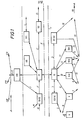
- FIG. 1 The fare collection and processing system of the present invention is illustrated in Figure 1 which shows the main components of the system and their inter-relationship. Only one station of the system is illustrated for clarity.
- the system illustrated is a distributed network of ticket issue machines, computer systems and associated gating devices and which provides automatic ticket issue, ticket checking and centralised accounting and statistical data.
- a number of ticket issue machines are installed together with ticket checking devices such as gates, all linked to a station computer (SC).
- the station computer system includes station control units (SCUs) which provide local control and monitoring of the various machines and enable printed accounting reports to be produced-
- SCUs station control units
- the station computers are linked via a telephone system (shown in Figure 1 by dot-dash lines X,Y) to a remote central computer system which provides a secure storage in its front end processors of all revenue and statistics data received from each station. This data is then converted by a data and protocol conversion system and transmitted to a central reporting system (CRS) which is a mainframe system external to the system of the present invention.
- CRM central reporting system
- the status of station equipment is monitored by central supervisory facilities and information made available on VDU terminals to an operations control centre (OCC) and to an engineering report centre (ERC) ( Figure 1) as hereinafter described.
- OCC operations control centre
- ERP engineering report centre
- the external central reporting system is supplied with accounts and statistics data to allow various reports to be produced for management.
- the system report centre (SRC) is used by the computer operators and data network, and to perform any computer system housekeeping necessary to effect a smooth running of the overall system.
- the station computer is linked to the central computers (CC) which pass information to the central reporting system (CRS).
- Reports and interogation data pass between the CRS and an accounts office 0 via link R/I and the office 0 supplies operations reports (OR) planning reports (PR) and engineering reports (ER).
- the office 0 also receives cash and statements from the bank from link A.
- the CR S supplies fares, book transactions, accounts and statistics data to the System Development/Support Centre via link J which also receives software system maintenance data and rules from a commercial office over links G and H respectively-
- the System Report Centre supplies and receives data to and from the central computers (CC) which receives control data from the operation control centre (CCC) which in turn receives status, alarms and reports from an operations centre over link L and supplies data thereto.
- Fault and diagnostics data is supplied from the central computers (CC) to the engineering report centre (ERC) via link E and link D enables interrogation of the ERC and the transmission of status, alarms and reports data.
- CC central computers
- ERP engineering report centre
- the station computer as controlled and controls the ticket hall SCC(a) and the ticket office SCU(b) over links 1 and 2 respectively and SCU(a) supplies control data to allow a travelling inspector to verify the data printed and encoded on a ticket by means of a portable verifier V; link 4 indicates the passing of tickets between the verifier V and the inspector.
- the gate G is linked to the inspector for ticket checks via link 5 and with the station computer-(SC) via link 6.
- Link 7 indicates tickets and credits from the gate G.
- the FFM's are linked to the SC via link 8 and supply tickets and cash via links 9, 10.
- the..MFM's along with the FFM's receive and transmit transaction accounts, statistics and status data to and from the SC via links 8 and 12 and the tickets and cash from the MFM's are shown by links 10, 13.
- the TOM's are linked to the SC via link 17 for rules and fare data and supplier tickets over link 14 to a clerks position who receives cash from the MFM's and FFM's and tickets from the TOM's.
- Link 15 indicates the communication between the clerks position and the booking hall SCU(b) and cash from the clerks position is supplied to a supervisor via link 16 who receives accounts summary and operating status data from the SCU(b). Cash from the supervisor is transmitted to the bank via joint A.
- TOM Ticket Office Ticket Issue Machine
- the TOMs of the system of the invention are used by booking office clerks to serve passengers through the window of a ticket office, with any of the types of tickets available on the system.
- Each clerk has his individual account records maintained by the TOM and tickets can only be issued after a clerk has identified himself to the TOM using a personal identity card and identification number (PIN).
- PIN personal identity card and identification number
- the clerk is presented with a printed account report at the end of each spell of duty, at the end of his shift and whenever an abnormal event has occurred or a ticket value or period has changed-
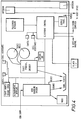
- the functional block diagram of a TOM is shown in Figure 2.
- the TOM consists of an issuing unit and a console for use by the clerk.
- Two types of partially preprinted ticket stock material are used, the appropriate type being automatically determined by the machine depending on the ticket requested by the operator. This allows a durable stock to be used for long-term tickets such as seasons, whilst a lower cost material may be used for short-term tickets such as singles and returns.
- the low-cost material is roll fed, whilst the durable material is pre-cut, and manually inserted for each such issue as required.
- the tickets are supplied from a ticket office window and a screen on the console indicates what is being transacted.
- the ticket issuing unit issues the ticket and a visual display available to the passenger provides data indicative of the fare at the time the ticket is issued or the value of a transaction made.
- a tally roll provided on the console prints in duplicate any flagged transaction, that is a non-standard transaction such as one where the fare has been keyed in. It also prints the accounts which are displayed concurrently on the screen and the summary accounts for clerk specifications and traffic days.
- Each TOM relies on the station computer (SC) for all its fare and ticket format data, but then having received this data, it can then operate independently of the SC until the audit data collected exceeds the capacity of the machine, at which point it will go out of service.
- SC station computer
- the TOM console consists of a keyboard, a display screen and a tally roll printer.
- a bank of keys relate to the most commonly used fares and depression of a key causes the ticket to be issued.
- a mother bank of keys allow tickets of any type to be printed and issued.
- Ten numeric keys are used to input such entries as station code, expiry dates and fares, if necessary. Further keys enable clerk accounts to be displayed (or printed) and tickets to be interpreted. This last mentioned function enables a ticket to be inserted in the ticket issuing unit, its magnetic data read off and displayed on the screen. Other keys on the keyboard are for operating change dispensing apparatus.
- the display provides an indication of the type of ticket being prepared including its serial number and price- If keys are depressed in an illogical order then a warning legend is displayed on the screen-Accounts are also displayed as are records at sign on and sign off.
- the tally roll printer is an ink ribbon needle type printer and prints whenever a sign on or sign off occurs, it prints accounts when requested or automatically and prints transactions when the 'value as keyed' key is depressed e.g. when a fare is manually entered, so that the validity of such transactions can be checked.
- the printer can, on request, print any screen display.
- the TOM issuing unit produces the ticket and delivers it to a counter.
- the operator Before producing tickets from the TOM, the operator must first sign on by turning a key to 'OPERATE' as appropriate, "swiping" his I.D. card in the slot and entering his personal identification number on the panel. To sign off, the key is turned to NORMAL. This panel will also display the state the machine is in and error codes relating to the machine.
- the tickets are cut from a roll mounted on the ticket issuing unit of the machine.
- the cut ticket passes under a print head that prints the information one one side of the stock. It is then magnetically encoded. The code on the ticket is then read to check that the encoding is correct. If it is correct the ticket is sent forward to the operator. If the read after write check indicates that the coding is unsatisfactory the ticket is returned via a diverter into a capture bin and a second ticket is produced. If the second ticket fails a third is produced, but if that fails the machine shuts down. This arrangement is intended to cope in the event of a local imperfection in the oxide coating of the ticket stock.
- the information for the printing and encoding resides in the TOM for each transaction- For each transaction a message is sent to the SC to indicate that a ticket has been produced. A record is kept in a power-loss protected battery protected Audit Register in the TOM of the total value of travel sold and at the end of his shift the operator obtains a record of this total that he must reconcile with cash taken. This information is also available at the SCU. A supervisor can use his card to obtain each operator's account on request and also a summary of accounts for all operators for any traffic day up to 6 days previously
- a display positioned at the window faces the passenger and indicates the value for the current transaction.
- the FFM is a passenger operated machine (POM) designed for use by the experienced passenger who knows the ticket/fare he wants and has valid coins to meet the.value of the ticket. Ticket selection is from one of ten buttons on the front panel of the machine. It is able to accept five coin denominations and issue change when available.
- the functional block diagram of a multi-fare machine is shown in Figure 3 and that of a few-fare machine in Figure 4.
- the multi-fare machine (MFM) is also a passenger operated machine (POM) but is intended for use by passengers who do not know their fare and who are unable to obtain a ticket from the FFM.
- the MFM allows the passenger to select from a number of destinations and ticket types. The fare to be paid is displayed to the passenger and it is able to accept five coins and one note denomination and issue change when available.
- Both types of POMs use the same identity card and personal identification number system to ensure that only authorised staff can gain access for cashing up the machines.
- the passenger presses the button corresponding to the ticket he wishes to purchase.
- the amount to pay is displayed on a red LED display and he is invited to insert coins; 5p, lOp, 20p, 50p and 100p coins are accepted-
- the "amount to pay" display is decremented and when zero the machine will issue the ticket.
- the machine is able to supply 5p, lOp, 20p, 50p coins in change when a predetermined number of coins is available in the tubes. These tubes capture inserted coins.
- the display will show the amount paid until a button is pressed, when it continues as before.
- a "Cancel” button will stop a transaction, clear the display and return the value of cash inserted, provided production of the ticket has not started.
- a "Call Assistance” button indication is provided at the SCU and sounds a warning buzzer in the ticket office.
- a flashing light asks the passenger to wait by the machine. The warning is cancelled by pressing a button fitted on top of the machine.
- a "CLOSED" sign indicates when the machine is not in service and coins cannot be inserted when this condition prevails.
- the ticket and change are delivered to a bowl.
- the paper is mounted in a similar fashion to the TOM.
- the printing and encoding processes are identical with the TOM and most parts are interchangeable.
- the fewfare machine does not rely on the SC and will stand alone if the SC has failed. However, in normal operation the machine will send transaction data to the SC at intervals and at sign on, and will receive new fares table information. If the SC is not operating properly then up to 28 sign-ons can be achieved. In this case transaction data and the vital data is stored in the Audit Register. A display on the service panel will indicate the number of sign-ons that remain before the store is filled.
- a printout at the local printer provides details of cash contents and value of tickets sold at the machine since the last service. This is reconciled by the operator against the money removed.
- the information concerning what tickets to produce for each button is contained in the fares data received from the SC. At a fare change this is automatically replaced, through communication with the SC. This command can be programmed in advance and requires no operating or maintenance staff action at the time of implementation, and at the same time button legends have to be altered.
- the multi-fare machine is designed for the passenger who does not know his fare or perhaps wishes to pay with five pound notes. It has a button for every station and eight buttons for eight types of ticket. It is twice the width of the fewfare machine
- the tickets produced are identical in format to the fewfare and TOM day tickets.
- the passenger first presses the button corresponding to the station he wishes to travel to and its name is displayed on a plasma display. He then presses one of the eight ticket type buttons and this is displayed similarly. The fare is displayed and a shutter across the coin insertion slot is opened. Illuminated legends are provided to assist the passenger to follow the correct sequence of operation.
- the passenger can now insert either 5p, lOp, 20p, 50p or 100p coins into the slot or five pound notes into the note acceptor.
- the "amount to pay" display is decremented and change is given and tickets are issued in the same manner as the fewfare machine.
- the passenger cannot insert money before selecting a ticket type.
- Insertion of five pound notes has to be one of two particular ways round as shown on the entry mouth. If the acceptor does not recognise the colour distribution pattern it is returned by reversing it out of the mouth. If accepted it is held in escrow and if the transaction is cancelled the note is returned through a slot lower down the machine. If the transaction is completed, it is passed from the escrow into a note vault. The machine is able to supply 5p, 10p, 50p and 100p coins in change when a predetermined number of coins is available in the tubes; as with the fewfare machine.
- the coin acceptor holds coins for change giving in tubes. These can be emptied to the coin vault when cash servicing if required.
- the ticket producing hardware is again similar to that of the fewfare machine as are many of the electronic components including the Audit Register.
- the multi-fare machine can operate without a station computer (SC) but will then accept up to 28 sign-ons before going out of service, like the fewfare.
- SC station computer
- the printouts that are produced by the multifare machine appear on the same printer as the fewfare machine.
- a number of centralised facilities are provided to alow staff to monitor, control and maintain various elements of the system.
- These facilities include the operations control centre (OCC) ( Figure 1) which monitors and controls the functions operation of the overall system, the engineering report centre (ERC) which controls the maintenance and repair of the various components of the system including station computers (SC's) peripherals and devices but excluding modems and communications lines, and a system report centre (SRC) which controls the maintenance and repair of the computer systems and peripherals at a central site but excluding modems and communications lines.
- OCC operations control centre
- ERP engineering report centre
- SRC system report centre
- the computer systems log all significant status changes of major components and maintain a data base containing the current status of each component along with its immediate history. This information is available to OCC and ERC staff on an enquiry basis and also as a series of regular reports- When status changes occur that require prompt attention from the staff, alarms and warning messages are produced automatically.
- the system provides centralised facilities to update commercial rules and fare tables via a system development facility and to update staff black-lists and station aliasing across the whole network via the operations control centre (OCC).
- OCC operations control centre
- the Operations Control Centre monitors and controls the functional operations of the system through the computer terminals and printers.
- the OCC monitors the TOM's, the MFM's, the FFM's, the Station Computers (SC's) and associated Station Control Units (SCU's), the central computers and associated peripherals and the communications links.
- the (OCC) monitors and controls the TOM's, MFM's, FFM's and any gating units of the system.
- Each of the components of the system is able to signal any significant status change to the Control Centre (OCC), and these changes are used to update a database which contains the current status of each component of the system, a log of all status changes for the current day, a log of all status changes for the previous day, and a log of all status changes for the day before the previous day.
- OCC Control Centre
- Significant status changes are status changes detected by a particular station level device e.g. ticket stock low, door of machine open, status changes detected by a station computer failure, and status changes in the central computer configuration e.g. failure to communicate with a particular station, terminal failure.
- Significant status changes also include text input from the Engineering Report Centre (ERC) e.g. action taken to repair a device, cause of fault, and messages sent from stations to the centre or from the centre to stations on user command.
- ERP Engineering Report Centre
- the ERC ( Figure 1) has a number of computer terminals and printers through which it monitors error conditions in the components of the system, and provides a logging mechanism for engineers to record maintenance and repair details for individual components of the system.
- the System Report Centre (SRC) ( Figure 1) has a number of system consoles for the central site computers- These consoles are used by the system to report significant hardware or software conditions and to accept operator commands to control the central and station computer (SC) systems (e.g. to load magnetic tape).
- SC central and station computer
- the system of the present invention provides a secure primary audit path from station devices to the central computer centre. Audit data is passed to the Management Information System for processing and report generation. A back-up path via an adjacent station is provided to allow collection of essential accounting data in the event of a failure of the direct communications between the station level and the computer centre.
- the ticket machines retain essential accounting data in secure audit registers. Each ticket machine keeps at least two independently calculated totals for value of tickets issued. In the case of POMs, records are kept of total cash accepted, kept cash where no ticket was issued and cash by denomination. As a result, the ticket machine can perform an internal account reconciliation and in a POM, a cash reconciliation. The account details are only made available to authorised personnel at station level through use of identity cards and personal identification numbers. Only booking clerks and supervisors would be authorised in this context.
- Passengers present cash to the POMs or booking clerk and receive tickets in return.
- the booking clerk receives cash from passengers in exchange for tickets and from servicing the POMs.
- the booking clerk receives accounts from the ticket machines against his identity card and personal identification number (PIN). These accounts are used to reconcile with cash collected from each POM servicing and TOM spell/duty.
- PIN personal identification number
- the supervisor receives cash and accounts from the booking clerks and also receives Accounts Summaries from the ticket machines (via the SCU Printer) against his identity card and PIN.
- the supervisor reconciles the accounts/cash at station level and banks the cash.
- Accounts and transaction data received at the Data Output Centre can be used to reproduce an internal reconciliation of the accounts.
- the Accounts Office receives the accounts reports from the CRS statements from the bank and control of the cash banked by all the supervisors.
- the Accounts Office reconciles the accounts against the bank statements and produces management accounting reports as appropriate.
- the Logical Trail described is implemented physically as a Primary Trail and a Secondary Trail. These are illustrated in Figure 8.
- (a) Primary Trail The Primary Trail is marked (1) in Figure 8 and is the path taken by audit data when the end-to-end connection is available.
- Secondary Trail The optional Secondary Trail is marked (2) in Figure 8. Secondary Trails are available in the case of failures of the following:
- the POMs and TOMs communicate with the station computer (SC).
- Passenger gates are arranged to open to provide entry to or exit from the system only when a valid ticket is presented thereto.
- the TOM's the passenger gates and the POM's, send details of transactions to the SC.
- the SC in turn communicates with the central computers which collect data from all stations and store the data for the preparation of reports.
- the central computers are also used to down line load programs and tables to the TOMs and multi-fare machines (MFMs) of the POMs via the station computer (SC).
- MFMs multi-fare machines
- terminals are provided representing the control centres from which operators could monitor the system and individual stations.
- Station Control Units are provided at each station (SCU(b) of Figure 1) and communicate through the SC with the POM's and passenger gates to enable them to be monitored and controlled from the clerk's position in the ticket office, or from another SCU in the ticket hall (SCU(a) of Figure 1) by a supervisor.
- a printer is installed to provide a printout of TOM's and POM audit data for local reconciliation of the station level accounts.
- the passenger gates are designed to open only when a valid ticket is inserted (although the Operator can open them manually via the SCU's).
- the reversible gate can be operated in entry or exit mode using a different transporter and set of doors in each case.
- a plurality of infra-red photocells monitor the passage of people through the gates.
- the gates and gating mechanism may be of the type described in GB Patents Nos. 1436712 and 1397186.
- a typical gating device layout is shown in Figure 6.
- the passenger inserts the ticket in the entry slot on the right hand stanchion as he enters.
- the ticket is taken by the first set of rollers into the transporter where it is read by a head.
- the ticket data is extracted and the gate uses its internal logic tables to determine whether the ticket is valid or not. If invalid, the gate returns the ticket to the passenger through the far slot, illuminates a sign reading "Seek Assistance" and sounds an audible warning. To aid staff a two digit code on the side of the gate indicates why the ticket was rejected and the gates remain closed.
- the gate finds the ticket valid, however, the gate generates a credit and causes the encoded data to be rewritten on the ticket.
- the gate confirms that the data has been written correctly by performing a read-after-write check. If this is the case, the ticket is returned to the passenger via the far slot and a sign is illuminated saying "Take Ticket". When the ticket is taken the doors open enabling the passenger to walk through. At this point the error display shows "00" indicating no error
- the infra-red beams ensure that the gate closes only when the passenger has passed. Up to three credits can be stored which would keep the gates open for the passage of three people and then close. If no-one goes through, the gate will close after a predetermined time e.g. 15 seconds (table loadable parameter).
- the infra-red beams pass through the perspex windows in the casing to reflectors mounted on the other side of the walkway.
- the logic employed to use the photocell data to control the doors is complex. Should a person try to push through a gate in either direction the warning will sound and a ticket entry shutter closes to prevent tickets from being inserted and hence prevent theft of credit.
- the ticket entry shutter also closes between the time a ticket is inserted and removed, this prevents two tickets from being in the transporter at the same time. The shutter also closes when three credits have been accumulated.
- SCU's Station Control Units
- SC Station Control Units
- a printer produces the POM cash service reports and prints error messages including POM power failures.
- the Ticket Office SCU indicates vandalism (back door opened without a valid sign), Out of Service or Fault, in test mode, in exact fare mode, cash servicing in progress, cash full (vault 80% full), change low, paper low (one roll out), assistance required, link between the POM and the SC not functioning.
- the SCU For each gate the SCU shows when a gate is out of service or has a fault, or when it is in test mode.
- the keyboard enables the operator to change the gate from entry to exit (or vice versa) or off (all doors shut) or released (which opens them for as long as the appropriate key is depressed).
- Another set of keys can be used to change the level or logic checks made on each ticket. For instance, "accept all tickets inwards" will give credit to any ticket presented provided it is coded. Thus it will not check for date, re-use, etc. and is useful when the correct tables are unavailable or faulty tickets are known to be in the system.
- Another facility is the ability to prevent Child Tickets from operating the gates.
- the separate emergency open control removes the air from the gates and allows passengers to push past-This feature is for emergencies requiring passengers to pass unhindered at times of failure or emergency.
- the Ticket Hall SCU(a) Figure 1 is similar to the Ticket Office SCU(b) but being in the passenger area, it has a lockable cover. Also, the facilities are somewhat different.
- the printer housed in the POM enclosure, will print an account for a POM whenever a valid sign-on is completed by an operator.
- Total cash and total ticket sales are included in the statement as are details for cash make-up and for sales by ticket types. This printout will also occur automatically at each "End-of-Day" to show the account state of each machine after each traffic day.
- This printer will also record the state of the POM accounts after that occur on the POM's.
- the machines have been designed around a modular system whereby most of the mechanisms and all the electronics are contained in units that can easily be unplugged, removed, replaced and reconnected to the body of the machine. Furthermore, many of these modules are common between different types of machines.
- the principle of repair is to use the error code or codes as displayed on the SP to identify which unit is faulty and to replace it in order to return the machine quickly to service. The faulty unit is then repaired off site.
- the booking office operator's task is made simpler by being able to produce all tickets and complete other transactions from one machine, rather than rely on card stocks- Hence no ticket is produced until required so there are no value stocks in the office that have to be accounted for.
- the tickets used and produced by the system are of a standard, credit-card size with printing on a coloured face and a magnetic coating on the back. Paper is used as the base material in POMs as those tickets are used for only one or two journeys.
- the TOMs normally use a stock based on plastics material, designed to be more durable when made as a season or travelcard.
- the station of origin (or zone details), date, serial number and machine number are all printed in clear in order that they can be read at barriers and by travelling ticket inspectors.
- the format varies slightly between types of tickets. Up to four lines of text can be printed to indicate availability of the ticket, i.e. travelcard, rail season, daily or test.
- the magnetic data is stored on a track 8mm wide at a density of 75 bits/inch. This data is of two types:
- FIG. 9 is a block diagram of the computer system network. Reference is made to both Figures 1 and 9 to illustrate the functions of the station computers (SC), the computer system network and the station control units (SCUs) and the inter-relationship therebetween.
- SC station computers
- SCU station control units
- Each Station Computer may consist of duplicated processors. Each machine contains the software necessary to support the SCU fares table loading of devices, and to pass the transactions and accounts data up to the Central Computers. One machine would perform all these functions, but should it not operate correctly, its partner machine would come into use.
- the SC communicates with each device through a multi-drop communications link as shown in Figure 5.
- Communications with the central computers is via a modem and a 4-wire telephone-type link.
- the Central Supervisory Computer (CSC) ( Figure 9) collects and records on disc and tape the data transmitted from site and will downline load a halted SC. In a full system the CSC would be linked to all sites. In addition the CSC can communicate faulty station and "aliasing" (in which a station assumes the logical identity of another as well as itself when a nearby station is closed in an emergency, for instance) and allow gate modes to be set up remotely.
- aliasing in which a station assumes the logical identity of another as well as itself when a nearby station is closed in an emergency, for instance
- Several remote VDU's are used to monitor system and device status at the operating control centre and engineering report centre. The data collected at the centre is used to complile;
- the Computer system equipment of the overall system at station level supports a number of distributed, intelligent ticketing devices capable of such operation, these devices are required to have the ability to communicate on line with the computer centre, such devices being the ticket office machines (TOMs), fewfare machines (FFMs), and the multi-fare machines (MFMs).
- TOMs ticket office machines
- FFMs fewfare machines
- MFMs multi-fare machines
- the Computer systems are also required to interface to the automatic gates and manual gates where provided.
- the Computer system equipment for both phases includes Station Control Unit (SCU) terminals and associated printers for local report and control functions.
- SCU Station Control Unit
- the functions of the computer system equipment at station level are to:
- Each station computer must be capable of supporting a number of attached station devices.
- the equipment must have the capability for supporting a duplicated system of SCs and communications links to station devices.
- duplication is optional- The software required to support duplicated SCs is provided even though no duplicate systems are configured into the initial network.
- SC duplicated set of SCs
- Each SCU is required to provide the following commands in normal mode:
- the SC equipment for station device monitoring and control provides the following functions:
- Each set of computer system equipment at a station is required to support two types of SCU VDU terminal.
- One type is identified as the Ticket Office SCU; the other as the Ticket Hall SCU.
- the Ticket Office SCU is required to have two associated hard copy printers.
- Different functions and display facilities are required. However, it must be possible for either SCU to provide both sets of functions and facilities as required except for printing functions.
- the SC is required to support secure and efficient, two way data communications between the station and the computer centre, and within the station, between an SC and station level devices including SCU terminals.
- the SC may support both a direct route between the station and the centre and an alternative route via a partner station.
- the communication links at station level will not be affected by the failure of any supported device i.e. communication between the SC and other devices in service will remain available. Similarly, it will be possible to add, remove or replace any device or SCU terminal without affecting the normal operation of the remainder of the system.
- An SCU is required to have two modes of operation - normal and supervisor. Station staff do not need to be logged onto an SCU terminal for normal mode operation.
- a supervisor is required to log on by keyboard entry of an identity and an assigned password for supervisor mode operation.
- the ticket office SCU is required to have two associated hard copy printers: one for TOM information, and one for POM information. These printers provide mutual backup capabilities and report on the following: sign on details, power failure recovery, out of service faults, unauthorised access, TOM supervisor interrogate and final accounts, and end of day accounts.
- Text message transmitted from the Operations Control Centre are displayed on a nominated SCU.
- the following station device status indications are available on the SCU terminal display: gate modes of operation and/or fault codes, gate capture bin 80% full, gate ticket monitoring and checking level setting, manual gate status, POM modes of operation (Passenger, Clerk, supervisor, engineer or fault code), POM ticket stock low (50%), POM exact money only, POM no notes mode (MFM only), POM coin vault greater than 80% full, POM note vault greater than 80% full (MFM only), POM passenger calling for assistance, POM unauthorised access, and TOM modes of operation (clerk, supervisor, engineer or fault code).
- the following ticket checking level settings are available for the automatic gates: normal (cancel selections below), accept all tickets inward, accept all tickets outward, no geography checks, all other stations faulty, set/accept emergency bit, and reject child tickets.
- Ticket type monitoring is required via an indicator on each gate.
- the setting of which types of ticket are to be monitored is made from a Ticket Hall SCU only. The following settings are available: normal (no indication required), child, pass, privilege, document required, travelcard or season, short distance travelcard or season, and platform or permit.
- the supervisor is required to sign on at a ticket office SCU terminal using his identity number and assigned password in order to employ supervisor commands. Whilst signed on in this mode, all normal mode commands must also be available.
- the ticket office SCU is required to provide the following commands in supervisor mode: TOM supervisor interrogate and final accounts, end of day accounts, local blacklisting, station computer system equipment and communications links status enquiry.
- the following data is sent by the TOM, MFM, FFM and automatic gate station level devices to the computer centre: machine status, plinth identity, machine identity, type machine, held table revision levels (for current and alternative tables), unauthorised access details, diagnostic error codes, sign on details, accounts and transaction data (not automatic gates), statistical data (automatic gates only), staff identity blacklist details, system messages (TOM only), and alarm messages.
- the manual gate device sends status information only.
- the following data is sent by the computer centre to the TOM, MFM, FFM and automatic gate station level devices: fare tables, date and time details, identity card blacklist information, and system message delivery acknowledgement (TOM only).
- the computer centre or a local SCU terminal can send controls to the above devices and also to the manual gate device. Text messages can also be sent by the centre to the SCU.
- the central system collects transaction data from all of the stations, safe-stores it at the central site and then sends it on to Central Reporting Systems computers where various data processng and reporting functions are performed.
- status information and user generated messages and data is safe-stored at the central site and then sent on to either the supervisory facilities or to the stations.
- safe-storage of data is defined as having a copy of the data on two separate disc packs.
- end-to-end acknowledgement is required for each message.
- the message source only discards the message after an acknowledgement has been received from the destination, signifying that the data has been successfully received and safe-stored. This means, for example, that station devices will not discard data until a positive acknowledgement has been received from the central computers. However, in the case of transactions, data may be discarded if the local storage within a device becomes full.
- this alternative path will be via an adjacent station, it may be provided as a second direct link, or there may be no alternative.
- FIG. 10 there is shown in diagrammatic form an automatic fare collection system for use on a railway Underground system which ensures that for any journey undertaken by a passenger, any ticket purchased by the passenger is validated at both entry and exit points of the journey.
- the system is divided into 'closed' stations and 'open' stations.
- the closed stations are under the control of a central computer linked to front-end processors and data concentrators which are in turn an area computer which is in turn linked to the respective station computer.
- each 'closed' station there is provided the passenger operated machines (POMs) and ticket office machines (TOMs), the POMs including multi-fare machines and fewfare machines previously referred to, and these are shown in the diagram for both the 'entry' station and the 'exit' station and the 'exit' station is provided with automatic passenger gating devices at entry and exit points and each gating device will have inbuilt ticket validation facilities.
- POMs passenger operated machines
- TOMs ticket office machines
- the system of the present invention provides ticket issue facilities, accounting facilities and communications facilities.
- (a) Ticket Issue Facilities include:
- (b) Accounting Facilities include:
Abstract
Description
- This invention relates to a fare collection and processing system and apparatus therefor particularly for use on railway systems such as the London Regional Transport Underground System, and a particular but not exclusive feature of the present invention is to provide an automatic fare collection system in which tickets are checked to verify the data thereon or determine their validity.
- The system and apparatus of the present invention includes ticket issue machines operated by a passenger (hereinafter termed passenger operated machines or POMs), and such POMs include few fare machines (FFMs) and multi-fare machines (MFMs) both hereinafter described. The system and apparatus of the present invention also includes ticket office machines (TOMs). All three types of ticket issue machines produce standard tickets printed on one face and magnetically encoded with data on the reverse side.
- At each station of the system, a number of ticket issue machines (TOMs, FFMs and MFMs) are installed and linked to a station computer (SC). The station computer system includes station control units (SCUs) which provide local control and monitoring of the ticket issue machines and enable printed accounting reports to be produced for the benefit of supervisory staff. Each station computer (SC) is linked via a communications system e.g. a telephone system to control computers for the transmission of accounting and statistical data and for the receipt of control commands and fare tables/commercial rules.
- Additionally at each station there is provided a facility to verify the data recorded on a ticket or to determine its validity. In one embodiment of the invention such a facility comprises a verifier, a version of which may be hand held and which is employed to read data recorded magnetically on the reverse side of each ticket and to display the information read. Such a verifier allows supervisory personnel to verify that the printed data recorded on the face of the ticket corresponds with data magnetically encoded on the reverse side of the ticket such as to detect any attempt to fraudulently amend the printed data or magnetically encoded data. Such a portable verifier is not linked to the station computer system.
- Alternatively, each station may be provided with one or more automatic passenger gates which are arranged to accept tickets originating from the ticket issue machines and presented to a slot in the gate by a passenger, and to determine the validity of the ticket. If valid, the ticket coding is arranged to be updated by the gate mechanism and the gate barrier, which may be in the form of paddles, operated to allow a passenger to proceed therethrough. The ticket may normally be returned to the passenger but at the termination of a journey for which the ticket is valid, the ticket may be captured. The gating devices are arranged to communicate with the station computer. With such a system each station computer supports the station control units (SCU's), the respective TOMs, the POMs and the passenger gates; with the TOM'S, POM's and passanger gates operating independently of the station computer (SC), but all devices send details of transactions to the station computer. The SCU's remain dependent on the SC.
- Thus, according to one aspect of the present invention there is provided a fare collection and processing system wherein there is provided at each of a plurality of stations, at least one passenger operated ticket issue machine and at least one ticket office ticket issue machine all arranged to communicate with a station computer, said machines operating independently of the station computer and sending details of transactions thereto, means for verifying data on tickets issued by said ticket issue means and operating independently of said station computer and said station computer of each station communicating with a central system computer arranged to collect data from all stations for storage and processing.
- In an embodiment of the invention, the ticket data verifying means comprises a verifier device arranged to compare data printed on one side of a ticket with data magnetically encoded on the reverse side of the ticket, said verifier being in one version, hand held.
- According to a further aspect of the present invention there is provided an automatic fare collection and processing system wherein there is provided at each of a plurality of stations, at least one passenger operated ticket machine, at least one ticket office ticket issue machine and at least one automatic passenger gating device, all arranged to communicate with a station computer, said machines and said at least one gating device operating independently of the station computer, and sending details of transactions thereto, said at least one gating device performing a validity check on any ticket presented thereto and operating to allow a passenger to pass therethrough only on presentation thereto of a valid ticket, and the station computer of each station communicating with at least one central computer arranged to collect data from all stations for storage and processing.
- In an embodiment of the invention, a station control unit (SCU) is linked via the station computer to the passenger operated machines and to the gating devices for the monitoring of these machines and devices from the station ticket offices.
- According to a'still further aspect of the present invention there is provided an automatic fare collection and processing system including 'open' and 'closed' type stations, and wherein there is provided at each of a plurality of 'closed' stations in the system, at least one ticket"office ticket issue machine and at least one passenger operated ticket issue machine and at least one automatic passenger gating device, all arranged to communicate with a station computer linked with a central computer and said stations having means at each entry and exit point for validating tickets presented thereto either forming part of the gating device, or in lieu thereof whereby no journey which commences or terminates within a closed station can be completed on the system without validation of a ticket at both entry and exit points of the system.
- The invention will now be described by way of example only with particular reference to the accompanying drawings wherein:
- Figure 1 is a block schematic diagram of the general layout of the system;
- Figure 2 is a functional block diagram of a ticket office ticket-issue machine;
- Figure 3 is a functional block diagram of a multi-fare machine;
- Figure 4 is a functional block diagram of a multi-fare machine;
- Figure 5 is a block diagram of the arrangement of machines and gates at station level;
- Figure 6 is a block diagram showing the layout of an automatic gating device;
- Figure 7 is a flow diagram of a logical audit trail;
- Figure 8 is a diagram of the physical audit trail;
- Figure 9 is a block diagram of the computer system network; and
- Figure 10 is a general schematic diagram of an underground ticketing system of the present invention.
- The fare collection and processing system of the present invention is illustrated in Figure 1 which shows the main components of the system and their inter-relationship. Only one station of the system is illustrated for clarity. The system illustrated is a distributed network of ticket issue machines, computer systems and associated gating devices and which provides automatic ticket issue, ticket checking and centralised accounting and statistical data.
- At each station as shown in Figure 5, a number of ticket issue machines (TOMs, FFMs, MFMs) are installed together with ticket checking devices such as gates, all linked to a station computer (SC). The station computer system includes station control units (SCUs) which provide local control and monitoring of the various machines and enable printed accounting reports to be produced- The station computers are linked via a telephone system (shown in Figure 1 by dot-dash lines X,Y) to a remote central computer system which provides a secure storage in its front end processors of all revenue and statistics data received from each station. This data is then converted by a data and protocol conversion system and transmitted to a central reporting system (CRS) which is a mainframe system external to the system of the present invention.
- The status of station equipment is monitored by central supervisory facilities and information made available on VDU terminals to an operations control centre (OCC) and to an engineering report centre (ERC) (Figure 1) as hereinafter described.
- The external central reporting system is supplied with accounts and statistics data to allow various reports to be produced for management.
- Updates to the system and new fares/commercial rules are developed on a system development/support centre (SD/RC) and when fully tested are loaded down to the Computer Centre under strict control.
- The system report centre (SRC) is used by the computer operators and data network, and to perform any computer system housekeeping necessary to effect a smooth running of the overall system.
- In Figure 1, the station computer (SC) is linked to the central computers (CC) which pass information to the central reporting system (CRS). Reports and interogation data pass between the CRS and an accounts office 0 via link R/I and the office 0 supplies operations reports (OR) planning reports (PR) and engineering reports (ER). The office 0 also receives cash and statements from the bank from link A. The CRS supplies fares, book transactions, accounts and statistics data to the System Development/Support Centre via link J which also receives software system maintenance data and rules from a commercial office over links G and H respectively- The System Report Centre (SRC) supplies and receives data to and from the central computers (CC) which receives control data from the operation control centre (CCC) which in turn receives status, alarms and reports from an operations centre over link L and supplies data thereto.
- Fault and diagnostics data is supplied from the central computers (CC) to the engineering report centre (ERC) via link E and link D enables interrogation of the ERC and the transmission of status, alarms and reports data.
- The station computer as controlled and controls the ticket hall SCC(a) and the ticket office SCU(b) over
links link 4 indicates the passing of tickets between the verifier V and the inspector. The gate G is linked to the inspector for ticket checks vialink 5 and with the station computer-(SC) vialink 6. Link 7 indicates tickets and credits from the gate G. The FFM's are linked to the SC via link 8 and supply tickets and cash vialinks links 8 and 12 and the tickets and cash from the MFM's are shown bylinks 10, 13. The TOM's are linked to the SC vialink 17 for rules and fare data and supplier tickets overlink 14 to a clerks position who receives cash from the MFM's and FFM's and tickets from the TOM's.Link 15 indicates the communication between the clerks position and the booking hall SCU(b) and cash from the clerks position is supplied to a supervisor vialink 16 who receives accounts summary and operating status data from the SCU(b). Cash from the supervisor is transmitted to the bank via joint A. - The TOMs of the system of the invention, are used by booking office clerks to serve passengers through the window of a ticket office, with any of the types of tickets available on the system. Each clerk has his individual account records maintained by the TOM and tickets can only be issued after a clerk has identified himself to the TOM using a personal identity card and identification number (PIN). The clerk is presented with a printed account report at the end of each spell of duty, at the end of his shift and whenever an abnormal event has occurred or a ticket value or period has changed- The functional block diagram of a TOM is shown in Figure 2. The TOM consists of an issuing unit and a console for use by the clerk.
- Two types of partially preprinted ticket stock material are used, the appropriate type being automatically determined by the machine depending on the ticket requested by the operator. This allows a durable stock to be used for long-term tickets such as seasons, whilst a lower cost material may be used for short-term tickets such as singles and returns. The low-cost material is roll fed, whilst the durable material is pre-cut, and manually inserted for each such issue as required. The tickets are supplied from a ticket office window and a screen on the console indicates what is being transacted. The ticket issuing unit issues the ticket and a visual display available to the passenger provides data indicative of the fare at the time the ticket is issued or the value of a transaction made.
- A tally roll provided on the console prints in duplicate any flagged transaction, that is a non-standard transaction such as one where the fare has been keyed in. It also prints the accounts which are displayed concurrently on the screen and the summary accounts for clerk specifications and traffic days.
- Each TOM relies on the station computer (SC) for all its fare and ticket format data, but then having received this data, it can then operate independently of the SC until the audit data collected exceeds the capacity of the machine, at which point it will go out of service.
- The TOM console consists of a keyboard, a display screen and a tally roll printer. A bank of keys relate to the most commonly used fares and depression of a key causes the ticket to be issued. A mother bank of keys allow tickets of any type to be printed and issued. Ten numeric keys are used to input such entries as station code, expiry dates and fares, if necessary. Further keys enable clerk accounts to be displayed (or printed) and tickets to be interpreted. This last mentioned function enables a ticket to be inserted in the ticket issuing unit, its magnetic data read off and displayed on the screen. Other keys on the keyboard are for operating change dispensing apparatus.
- The display provides an indication of the type of ticket being prepared including its serial number and price- If keys are depressed in an illogical order then a warning legend is displayed on the screen-Accounts are also displayed as are records at sign on and sign off.
- The tally roll printer is an ink ribbon needle type printer and prints whenever a sign on or sign off occurs, it prints accounts when requested or automatically and prints transactions when the 'value as keyed' key is depressed e.g. when a fare is manually entered, so that the validity of such transactions can be checked. The printer can, on request, print any screen display.
- The TOM issuing unit produces the ticket and delivers it to a counter. Before producing tickets from the TOM, the operator must first sign on by turning a key to 'OPERATE' as appropriate, "swiping" his I.D. card in the slot and entering his personal identification number on the panel. To sign off, the key is turned to NORMAL. This panel will also display the state the machine is in and error codes relating to the machine.
- The tickets are cut from a roll mounted on the ticket issuing unit of the machine.
- When a ticket is requested, the cut ticket passes under a print head that prints the information one one side of the stock. It is then magnetically encoded. The code on the ticket is then read to check that the encoding is correct. If it is correct the ticket is sent forward to the operator. If the read after write check indicates that the coding is unsatisfactory the ticket is returned via a diverter into a capture bin and a second ticket is produced. If the second ticket fails a third is produced, but if that fails the machine shuts down. This arrangement is intended to cope in the event of a local imperfection in the oxide coating of the ticket stock.
- The information for the printing and encoding resides in the TOM for each transaction- For each transaction a message is sent to the SC to indicate that a ticket has been produced. A record is kept in a power-loss protected battery protected Audit Register in the TOM of the total value of travel sold and at the end of his shift the operator obtains a record of this total that he must reconcile with cash taken. This information is also available at the SCU. A supervisor can use his card to obtain each operator's account on request and also a summary of accounts for all operators for any traffic day up to 6 days previously
- A display positioned at the window faces the passenger and indicates the value for the current transaction.
- These consist of few fare machines (FFMs) and multi-fare machines (MFMs). The FFM is a passenger operated machine (POM) designed for use by the experienced passenger who knows the ticket/fare he wants and has valid coins to meet the.value of the ticket. Ticket selection is from one of ten buttons on the front panel of the machine. It is able to accept five coin denominations and issue change when available. The functional block diagram of a multi-fare machine is shown in Figure 3 and that of a few-fare machine in Figure 4. The multi-fare machine (MFM) is also a passenger operated machine (POM) but is intended for use by passengers who do not know their fare and who are unable to obtain a ticket from the FFM. The MFM allows the passenger to select from a number of destinations and ticket types. The fare to be paid is displayed to the passenger and it is able to accept five coins and one note denomination and issue change when available.
- Both types of POMs use the same identity card and personal identification number system to ensure that only authorised staff can gain access for cashing up the machines.
- In operation, the passenger presses the button corresponding to the ticket he wishes to purchase. The amount to pay is displayed on a red LED display and he is invited to insert coins; 5p, lOp, 20p, 50p and 100p coins are accepted- As money is inserted the "amount to pay" display is decremented and when zero the machine will issue the ticket. The machine is able to supply 5p, lOp, 20p, 50p coins in change when a predetermined number of coins is available in the tubes. These tubes capture inserted coins. If more than the required money is inserted in "change given" mode, then the appropriate change is dispensed with the ticket- If it is in "exact money" mode, and more than the required amount of money is inserted, no ticket is issued and all the money is returned. The machine changes automatically between "change given" and "exact money" modes when the correct conditions exist.
- If the passenger chooses to insert money before pressing a button, the display will show the amount paid until a button is pressed, when it continues as before.
- A "Cancel" button will stop a transaction, clear the display and return the value of cash inserted, provided production of the ticket has not started.
- A "Call Assistance" button indication is provided at the SCU and sounds a warning buzzer in the ticket office. A flashing light asks the passenger to wait by the machine. The warning is cancelled by pressing a button fitted on top of the machine.
- A "CLOSED" sign indicates when the machine is not in service and coins cannot be inserted when this condition prevails.
- The ticket and change are delivered to a bowl. The paper is mounted in a similar fashion to the TOM. The printing and encoding processes are identical with the TOM and most parts are interchangeable.
- The fewfare machine does not rely on the SC and will stand alone if the SC has failed. However, in normal operation the machine will send transaction data to the SC at intervals and at sign on, and will receive new fares table information. If the SC is not operating properly then up to 28 sign-ons can be achieved. In this case transaction data and the vital data is stored in the Audit Register. A display on the service panel will indicate the number of sign-ons that remain before the store is filled.
- At each sign on, whatever the state of the SC, a printout at the local printer provides details of cash contents and value of tickets sold at the machine since the last service. This is reconciled by the operator against the money removed.
- The information concerning what tickets to produce for each button is contained in the fares data received from the SC. At a fare change this is automatically replaced, through communication with the SC. This command can be programmed in advance and requires no operating or maintenance staff action at the time of implementation, and at the same time button legends have to be altered.
- The multi-fare machine is designed for the passenger who does not know his fare or perhaps wishes to pay with five pound notes. It has a button for every station and eight buttons for eight types of ticket. It is twice the width of the fewfare machine The tickets produced are identical in format to the fewfare and TOM day tickets.
- The passenger first presses the button corresponding to the station he wishes to travel to and its name is displayed on a plasma display. He then presses one of the eight ticket type buttons and this is displayed similarly. The fare is displayed and a shutter across the coin insertion slot is opened. Illuminated legends are provided to assist the passenger to follow the correct sequence of operation.
- The passenger can now insert either 5p, lOp, 20p, 50p or 100p coins into the slot or five pound notes into the note acceptor. As coins or notes are accepted, the "amount to pay" display is decremented and change is given and tickets are issued in the same manner as the fewfare machine.
- Unlike the fewfare machine, the passenger cannot insert money before selecting a ticket type.
- "Exact Money"/"Change Given" signs and "Cancel"/"Call Assistance" buttons are similar to the fewfare, as is the ticket/change bowl.
- Insertion of five pound notes has to be one of two particular ways round as shown on the entry mouth. If the acceptor does not recognise the colour distribution pattern it is returned by reversing it out of the mouth. If accepted it is held in escrow and if the transaction is cancelled the note is returned through a slot lower down the machine. If the transaction is completed, it is passed from the escrow into a note vault. The machine is able to supply 5p, 10p, 50p and 100p coins in change when a predetermined number of coins is available in the tubes; as with the fewfare machine.
- The coin acceptor holds coins for change giving in tubes. These can be emptied to the coin vault when cash servicing if required.
- The ticket producing hardware is again similar to that of the fewfare machine as are many of the electronic components including the Audit Register.
- The multi-fare machine can operate without a station computer (SC) but will then accept up to 28 sign-ons before going out of service, like the fewfare. The printouts that are produced by the multifare machine appear on the same printer as the fewfare machine.
- When first switched on the multi-fare machine relies on the SC for the fare tables that it requires to operate. When a fare change occurs, these tables are replaced by a new set on command from the SC. This command can be programmed in advance and normally requires no operating or maintenance staff action at the time of implementation.
- A number of centralised facilities are provided to alow staff to monitor, control and maintain various elements of the system. These facilities include the operations control centre (OCC) (Figure 1) which monitors and controls the functions operation of the overall system, the engineering report centre (ERC) which controls the maintenance and repair of the various components of the system including station computers (SC's) peripherals and devices but excluding modems and communications lines, and a system report centre (SRC) which controls the maintenance and repair of the computer systems and peripherals at a central site but excluding modems and communications lines.
- To meet these operational requirements, the computer systems log all significant status changes of major components and maintain a data base containing the current status of each component along with its immediate history. This information is available to OCC and ERC staff on an enquiry basis and also as a series of regular reports- When status changes occur that require prompt attention from the staff, alarms and warning messages are produced automatically.
- The system provides centralised facilities to update commercial rules and fare tables via a system development facility and to update staff black-lists and station aliasing across the whole network via the operations control centre (OCC).
- The Operations Control Centre (OCC Figure 1 monitors and controls the functional operations of the system through the computer terminals and printers. The OCC monitors the TOM's, the MFM's, the FFM's, the Station Computers (SC's) and associated Station Control Units (SCU's), the central computers and associated peripherals and the communications links. In addition, the (OCC) monitors and controls the TOM's, MFM's, FFM's and any gating units of the system.
- Each of the components of the system is able to signal any significant status change to the Control Centre (OCC), and these changes are used to update a database which contains the current status of each component of the system, a log of all status changes for the current day, a log of all status changes for the previous day, and a log of all status changes for the day before the previous day.
- Significant status changes are status changes detected by a particular station level device e.g. ticket stock low, door of machine open, status changes detected by a station computer failure, and status changes in the central computer configuration e.g. failure to communicate with a particular station, terminal failure. Significant status changes also include text input from the Engineering Report Centre (ERC) e.g. action taken to repair a device, cause of fault, and messages sent from stations to the centre or from the centre to stations on user command.
- The ERC (Figure 1) has a number of computer terminals and printers through which it monitors error conditions in the components of the system, and provides a logging mechanism for engineers to record maintenance and repair details for individual components of the system.
- The System Report Centre (SRC) (Figure 1) has a number of system consoles for the central site computers- These consoles are used by the system to report significant hardware or software conditions and to accept operator commands to control the central and station computer (SC) systems (e.g. to load magnetic tape).
- The system of the present invention provides a secure primary audit path from station devices to the central computer centre. Audit data is passed to the Management Information System for processing and report generation. A back-up path via an adjacent station is provided to allow collection of essential accounting data in the event of a failure of the direct communications between the station level and the computer centre.
- The logical audit trail is shown in Figure 7.
- At the station level the ticket machines retain essential accounting data in secure audit registers. Each ticket machine keeps at least two independently calculated totals for value of tickets issued. In the case of POMs, records are kept of total cash accepted, kept cash where no ticket was issued and cash by denomination. As a result, the ticket machine can perform an internal account reconciliation and in a POM, a cash reconciliation. The account details are only made available to authorised personnel at station level through use of identity cards and personal identification numbers. Only booking clerks and supervisors would be authorised in this context.
- The full details of each individual transaction and the summary accounts are sent to the Computer Centre and acknowledged back to the ticket machines. Only when an acknowledgement has been received from the Centre and from the supervisor locally will the ticket machine discard the accounts data.
- Passengers present cash to the POMs or booking clerk and receive tickets in return.
- The booking clerk receives cash from passengers in exchange for tickets and from servicing the POMs. The booking clerk receives accounts from the ticket machines against his identity card and personal identification number (PIN). These accounts are used to reconcile with cash collected from each POM servicing and TOM spell/duty. The accounts.and cash are passed to the supervisor.
- The supervisor receives cash and accounts from the booking clerks and also receives Accounts Summaries from the ticket machines (via the SCU Printer) against his identity card and PIN. The supervisor reconciles the accounts/cash at station level and banks the cash.
- Accounts and transaction data received at the Data Output Centre can be used to reproduce an internal reconciliation of the accounts.
- The Accounts Office receives the accounts reports from the CRS statements from the bank and control of the cash banked by all the supervisors. The Accounts Office reconciles the accounts against the bank statements and produces management accounting reports as appropriate.
- Note that individual transaction records are created by the ticket issue machines for each ticket issued. These are stored in a non-volatile memory and where possible are transmitted to the central computers. In the event that the transaction store for the machine becomes full the subsequent transaction records overwrite previously stored records 'oldest first'. The transaction store sizes for each type of ticket issue machine have been estimated to be sufficient for a worst case 48 hours use.
- The Logical Trail described is implemented physically as a Primary Trail and a Secondary Trail. These are illustrated in Figure 8.
- (a) Primary Trail: The Primary Trail is marked (1) in Figure 8 and is the path taken by audit data when the end-to-end connection is available.
- (b) Secondary Trail: The optional Secondary Trail is marked (2) in Figure 8. Secondary Trails are available in the case of failures of the following:
- device to Station Computer link failed (either)
- Station Computer failed (either)
- device to Station Computer link failed (either and Station Computer failed (other)
- Front End Processor to Station Computer link failed
- Front End Processor failed (one only).
- Summarising the above, the POMs and TOMs communicate with the station computer (SC). Passenger gates are arranged to open to provide entry to or exit from the system only when a valid ticket is presented thereto. The TOM's the passenger gates and the POM's, send details of transactions to the SC. The SC in turn communicates with the central computers which collect data from all stations and store the data for the preparation of reports. The central computers are also used to down line load programs and tables to the TOMs and multi-fare machines (MFMs) of the POMs via the station computer (SC).
- As shown in Figure 1, terminals are provided representing the control centres from which operators could monitor the system and individual stations.
- Station Control Units (SCU's) are provided at each station (SCU(b) of Figure 1) and communicate through the SC with the POM's and passenger gates to enable them to be monitored and controlled from the clerk's position in the ticket office, or from another SCU in the ticket hall (SCU(a) of Figure 1) by a supervisor. In addition a printer is installed to provide a printout of TOM's and POM audit data for local reconciliation of the station level accounts.
- The passenger gates are designed to open only when a valid ticket is inserted (although the Operator can open them manually via the SCU's). The reversible gate can be operated in entry or exit mode using a different transporter and set of doors in each case. A plurality of infra-red photocells monitor the passage of people through the gates. The gates and gating mechanism may be of the type described in GB Patents Nos. 1436712 and 1397186. A typical gating device layout is shown in Figure 6.
- The passenger inserts the ticket in the entry slot on the right hand stanchion as he enters. The ticket is taken by the first set of rollers into the transporter where it is read by a head. The ticket data is extracted and the gate uses its internal logic tables to determine whether the ticket is valid or not. If invalid, the gate returns the ticket to the passenger through the far slot, illuminates a sign reading "Seek Assistance" and sounds an audible warning. To aid staff a two digit code on the side of the gate indicates why the ticket was rejected and the gates remain closed. If the gate finds the ticket valid, however, the gate generates a credit and causes the encoded data to be rewritten on the ticket. The gate confirms that the data has been written correctly by performing a read-after-write check. If this is the case, the ticket is returned to the passenger via the far slot and a sign is illuminated saying "Take Ticket". When the ticket is taken the doors open enabling the passenger to walk through. At this point the error display shows "00" indicating no error.
- The infra-red beams ensure that the gate closes only when the passenger has passed. Up to three credits can be stored which would keep the gates open for the passage of three people and then close. If no-one goes through, the gate will close after a predetermined time e.g. 15 seconds (table loadable parameter). The infra-red beams pass through the perspex windows in the casing to reflectors mounted on the other side of the walkway.
- If the ticket inserted is recognised as a Child Ticket a lamp above the gate is illuminated and an audible warning sound generated to identify passengers using Child Tickets.
- The logic employed to use the photocell data to control the doors is complex. Should a person try to push through a gate in either direction the warning will sound and a ticket entry shutter closes to prevent tickets from being inserted and hence prevent theft of credit. The ticket entry shutter also closes between the time a ticket is inserted and removed, this prevents two tickets from being in the transporter at the same time. The shutter also closes when three credits have been accumulated.
- The doors, when closed are locked in place such that reasonable pressure against them will not force them open. A high force, equivalent to a person hitting them very heavily will just open them; this feature is intended to prevent injury to passengers using the gates, say in an unruly crowd.
- On the exit side, valid tickets which give a credit and have no further validity are captured in a ticket bin.
- To enable station staff to monitor and control the operation of gates and POMs and to provide a POM local audit printout it is necessary to employ Station Control Units (SCU's) supported by the SC which is connected by multi-dropped lines to the POM's and gates. Its interface with the operators is by means of two display terminals, one in the ticket office near the booking clerks position and one in the ticket hall for supervisory staff to use. These are standard VDU's with adapted keyboards. A printer produces the POM cash service reports and prints error messages including POM power failures.
- The Ticket Office SCU indicates vandalism (back door opened without a valid sign), Out of Service or Fault, in test mode, in exact fare mode, cash servicing in progress, cash full (vault 80% full), change low, paper low (one roll out), assistance required, link between the POM and the SC not functioning.
- For each gate the SCU shows when a gate is out of service or has a fault, or when it is in test mode. The keyboard enables the operator to change the gate from entry to exit (or vice versa) or off (all doors shut) or released (which opens them for as long as the appropriate key is depressed).
- Another set of keys can be used to change the level or logic checks made on each ticket. For instance, "accept all tickets inwards" will give credit to any ticket presented provided it is coded. Thus it will not check for date, re-use, etc. and is useful when the correct tables are unavailable or faulty tickets are known to be in the system.
- Another facility is the ability to prevent Child Tickets from operating the gates.
- The separate emergency open control removes the air from the gates and allows passengers to push past-This feature is for emergencies requiring passengers to pass unhindered at times of failure or emergency.
- The Ticket Hall SCU(a) Figure 1, is similar to the Ticket Office SCU(b) but being in the passenger area, it has a lockable cover. Also, the facilities are somewhat different.
- There are a number of status indications for each POM e.g. Preparations, Change Low, Cash Full and Cash Service) but the keyboard enables supervisors to monitor tickets through the gates- To achieve this a selection of keys are pressed corresponding to the type of ticket the supervisor wishes to monitor, such as privilege tickets. Eight types of ticket can be monitored and more than one can be monitored at once if required. When a ticket of the type selected is used in a gate a small arrow is illuminated pointing to the relevant gate from the side where the passenger leaves it. Thus, when the light is illuminated the supervisor is aware of the type of ticket being used.
- The printer, housed in the POM enclosure, will print an account for a POM whenever a valid sign-on is completed by an operator. Total cash and total ticket sales are included in the statement as are details for cash make-up and for sales by ticket types. This printout will also occur automatically at each "End-of-Day" to show the account state of each machine after each traffic day.
- This printer will also record the state of the POM accounts after that occur on the POM's.
- The machines have been designed around a modular system whereby most of the mechanisms and all the electronics are contained in units that can easily be unplugged, removed, replaced and reconnected to the body of the machine. Furthermore, many of these modules are common between different types of machines. The principle of repair is to use the error code or codes as displayed on the SP to identify which unit is faulty and to replace it in order to return the machine quickly to service. The faulty unit is then repaired off site.
- It is possible to use the SPP to carry out diagnostics checks on such items as photocells and jammed buttons.
- The booking office operator's task is made simpler by being able to produce all tickets and complete other transactions from one machine, rather than rely on card stocks- Hence no ticket is produced until required so there are no value stocks in the office that have to be accounted for.
- The tickets used and produced by the system are of a standard, credit-card size with printing on a coloured face and a magnetic coating on the back. Paper is used as the base material in POMs as those tickets are used for only one or two journeys. The TOMs normally use a stock based on plastics material, designed to be more durable when made as a season or travelcard.
- The station of origin (or zone details), date, serial number and machine number are all printed in clear in order that they can be read at barriers and by travelling ticket inspectors. The format varies slightly between types of tickets. Up to four lines of text can be printed to indicate availability of the ticket, i.e. travelcard, rail season, daily or test.
- The magnetic data is stored on a track 8mm wide at a density of 75 bits/inch. This data is of two types:
- (a) fixed data set at time of issue and corresponding to the information printed on the front of the ticket; and
- (b) variable data used to detect fraud. Although the whole code is rewritten by a gate it is only the variable data that changes. The information covered by the magnetic data includes the following: Ticket Type, Station of Origin, Fare Value in pence concession types, e.g. Child, Station of Destination, routing, end of validity and day and time last processed- Other bits are used to control how often a ticket is used and to prevent pass back frauds.
- At the gate the ticket is checked to see:
- (a) that it is valid at that station at that time; and
- (b) that it has not been used to perpetuate an apparent fraud.
- Allowance has to be made for Out of Station Interchanges where a passenger using an exit barrier may require to re-enter another barrier to interchange between lines.
- Figure 9 is a block diagram of the computer system network. Reference is made to both Figures 1 and 9 to illustrate the functions of the station computers (SC), the computer system network and the station control units (SCUs) and the inter-relationship therebetween.
- Each Station Computer (SC) may consist of duplicated processors. Each machine contains the software necessary to support the SCU fares table loading of devices, and to pass the transactions and accounts data up to the Central Computers. One machine would perform all these functions, but should it not operate correctly, its partner machine would come into use.
- The SC communicates with each device through a multi-drop communications link as shown in Figure 5.
- Communications with the central computers is via a modem and a 4-wire telephone-type link.
- The Central Supervisory Computer (CSC) (Figure 9) collects and records on disc and tape the data transmitted from site and will downline load a halted SC. In a full system the CSC would be linked to all sites. In addition the CSC can communicate faulty station and "aliasing" (in which a station assumes the logical identity of another as well as itself when a nearby station is closed in an emergency, for instance) and allow gate modes to be set up remotely. Several remote VDU's are used to monitor system and device status at the operating control centre and engineering report centre. The data collected at the centre is used to complile;
- (a) event logs describing all changes of state of devices at the station;
- (b) revenue reports; and
- (c) statistical reports as required by various departments.
- The Computer system equipment of the overall system at station level supports a number of distributed, intelligent ticketing devices capable of such operation, these devices are required to have the ability to communicate on line with the computer centre, such devices being the ticket office machines (TOMs), fewfare machines (FFMs), and the multi-fare machines (MFMs).
- The Computer systems are also required to interface to the automatic gates and manual gates where provided.
- The Computer system equipment for both phases includes Station Control Unit (SCU) terminals and associated printers for local report and control functions.
- The functions of the computer system equipment at station level are to:
- collect data (e.g. status, accounts, transactions) from station devices and pass this to the computer centre;
- collect gate statistics from all gates at the station when requested by the centre and pass these statistics to the centre;
- monitor those elements of this collected data concerned with the status of station level equipments (attached station devices and computer system elements) and report locally at station control unit (SCU) terminals;
- maintain data tables received from the centre, downloading them to station devices as required;
- forward controls received from the centre or an SCU terminal to station devices as appropriate;
- maintain station accounts by the collection of accounts data and summaries for devices and by the production of reports on command from an SCU terminal;
- manage and control attached SCU terminals and associated printer; and
- support secure and efficient data communications to/from station level devices and to/from the computer centre.
- Each station computer (SC), must be capable of supporting a number of attached station devices. In addition, the equipment must have the capability for supporting a duplicated system of SCs and communications links to station devices. Such duplication is optional- The software required to support duplicated SCs is provided even though no duplicate systems are configured into the initial network.
- At very large or geographically diverse stations more than one SC (or duplicated set of SCs) are required to handle the station devices to be supported.
- Each SCU is required to provide the following commands in normal mode:
- - automatic gate emergency open
- - emergency open reset
- - automatic gate release
- - automatic gate closed mode (entry mode gates only)
- - automatic gate entry mode
- - automatic gate exit mode
- - automatic gate array open (array = group of gates)
- - automatic gate array closed
- - override child alarm (entry mode gates only)
- - automatic gate ticket return (outward gates only)
- - manual gate open (unlocks gate)
- - manual gate close (locks gate when next closed)
- - POM closed mode.
- The SC equipment for station device monitoring and control provides the following functions:
- (a) Data Collection
- The SC collects data from ticket issuing and ticket checking station devices on a regular basis. All data is required to be onward transmitted to the Computer centre via local buffering at the SC.
- This process is also required to cater for failure situations where a station device has been operating autonomously for some period and thus where data for collection has been buffered by the device itself.
- (b) Status Monitoring and Report
- The SC is required to monitor status change information collected from station devices in order that such changes may be reported locally for SCU display and output to an associated printer as appropriate.
- In addition, the SC is required to monitor the status of the other, locally attached SC (in the case of duplicated SCs) and the status of communication links between the station and the centre, the station and a partner station, and the links with devices at station level. These statuses are reported to the centre but are reported locally only when requested by a supervisor logged on at an SCU.
- (c) Data Table Maintenance and Management
- The SC is required to maintain copies of that dynamic data needed to reload a station device following a device failure and return to service. Copies of both current data and alternative data applicable following a fares revision or system update) must be maintained.
- The types of dynamic data held are: fares tables, date and time details, and identity card blacklist information, ticket printing and coding data.
- The SC is required to recognise a device request for reload, determine the data set applicable, and perform the request download whilst continuing to monitor the other devices.
- (d) Station Device Controls
- Station devices may receive controls from the centre or from any local station Control Unit.
- The SC is required to validate the command received given current knowledge of the device status, implement the command if valid, respond to the command initiator appropriately indicating any reason for failure, and if appropriate, reflect the new device status at the SCU terminals.
- (e) Station Account Maintenance and Report
- The SC is required to monitor all accounts data collected from station devices in order that up to date summary accounts are available for each connected TOM and POM station device.
- Whilst each individual TOM maintains its own accounts for the production of summaries requested by either clerk or supervisor, the SC is required to have access to that information of 'Supervisor Interrogate' and 'Supervisor Final' accounts for any specific TOM, or all TOMs, monitored by this SCU.
- The end of day accounting functions carried out by a supervisor require both the production of 'Supervisor Final' accounts for all associated TOMs and similar final accounts for all associated POMs.
- Each set of computer system equipment at a station is required to support two types of SCU VDU terminal. One type is identified as the Ticket Office SCU; the other as the Ticket Hall SCU. The Ticket Office SCU is required to have two associated hard copy printers. Dependent upon the identified usage of an SCU, different functions and display facilities are required. However, it must be possible for either SCU to provide both sets of functions and facilities as required except for printing functions.
- The SC is required to support secure and efficient, two way data communications between the station and the computer centre, and within the station, between an SC and station level devices including SCU terminals. The SC may support both a direct route between the station and the centre and an alternative route via a partner station.
- The communication links at station level will not be affected by the failure of any supported device i.e. communication between the SC and other devices in service will remain available. Similarly, it will be possible to add, remove or replace any device or SCU terminal without affecting the normal operation of the remainder of the system.
- All data collected from station level devices requires end to end acknowledgement from a secure data capture point at the Central Computer. However, due to the SC functions of account summary reporting, status monitoring and report, and so on, the link between station devices and SC requires a high level of error detection since the SC requires accurate data upon which to operate.
- An SCU is required to have two modes of operation - normal and supervisor. Station staff do not need to be logged onto an SCU terminal for normal mode operation. A supervisor is required to log on by keyboard entry of an identity and an assigned password for supervisor mode operation.
- The ticket office SCU is required to have two associated hard copy printers: one for TOM information, and one for POM information. These printers provide mutual backup capabilities and report on the following: sign on details, power failure recovery, out of service faults, unauthorised access, TOM supervisor interrogate and final accounts, and end of day accounts.
- Text message transmitted from the Operations Control Centre are displayed on a nominated SCU.
- The following station device status indications are available on the SCU terminal display: gate modes of operation and/or fault codes, gate capture bin 80% full, gate ticket monitoring and checking level setting, manual gate status, POM modes of operation (Passenger, Clerk, supervisor, engineer or fault code), POM ticket stock low (50%), POM exact money only, POM no notes mode (MFM only), POM coin vault greater than 80% full, POM note vault greater than 80% full (MFM only), POM passenger calling for assistance, POM unauthorised access, and TOM modes of operation (clerk, supervisor, engineer or fault code).
- All the above are available at a ticket office SCU terminal whereas only a limited display is available at a ticket hall SCU terminal. An audible warning is required with certain of the above status changes.
- The following ticket checking level settings are available for the automatic gates: normal (cancel selections below), accept all tickets inward, accept all tickets outward, no geography checks, all other stations faulty, set/accept emergency bit, and reject child tickets.
- All automatic gates under the control of the SCU are set at the same checking level, by barrier line groups.
- Ticket type monitoring is required via an indicator on each gate. The setting of which types of ticket are to be monitored is made from a Ticket Hall SCU only. The following settings are available: normal (no indication required), child, pass, privilege, document required, travelcard or season, short distance travelcard or season, and platform or permit.
- The supervisor is required to sign on at a ticket office SCU terminal using his identity number and assigned password in order to employ supervisor commands. Whilst signed on in this mode, all normal mode commands must also be available.
- The ticket office SCU is required to provide the following commands in supervisor mode: TOM supervisor interrogate and final accounts, end of day accounts, local blacklisting, station computer system equipment and communications links status enquiry.
- The following data is sent by the TOM, MFM, FFM and automatic gate station level devices to the computer centre: machine status, plinth identity, machine identity, type machine, held table revision levels (for current and alternative tables), unauthorised access details, diagnostic error codes, sign on details, accounts and transaction data (not automatic gates), statistical data (automatic gates only), staff identity blacklist details, system messages (TOM only), and alarm messages. The manual gate device sends status information only.
- The following data is sent by the computer centre to the TOM, MFM, FFM and automatic gate station level devices: fare tables, date and time details, identity card blacklist information, and system message delivery acknowledgement (TOM only). In addition, the computer centre or a local SCU terminal can send controls to the above devices and also to the manual gate device. Text messages can also be sent by the centre to the SCU.
- The central system collects transaction data from all of the stations, safe-stores it at the central site and then sends it on to Central Reporting Systems computers where various data processng and reporting functions are performed. In addition, status information and user generated messages and data is safe-stored at the central site and then sent on to either the supervisory facilities or to the stations. In this context safe-storage of data is defined as having a copy of the data on two separate disc packs.
- To ensure data integrity, end-to-end acknowledgement is required for each message. The message source only discards the message after an acknowledgement has been received from the destination, signifying that the data has been successfully received and safe-stored. This means, for example, that station devices will not discard data until a positive acknowledgement has been received from the central computers. However, in the case of transactions, data may be discarded if the local storage within a device becomes full.
- In the event of a link failure between a station and the central computers, the computer systems will attempt to find an alternative communications path. In some cases this alternative path will be via an adjacent station, it may be provided as a second direct link, or there may be no alternative.
- Referring to Figure 10 there is shown in diagrammatic form an automatic fare collection system for use on a Railway Underground system which ensures that for any journey undertaken by a passenger, any ticket purchased by the passenger is validated at both entry and exit points of the journey. The system is divided into 'closed' stations and 'open' stations. The closed stations are under the control of a central computer linked to front-end processors and data concentrators which are in turn an area computer which is in turn linked to the respective station computer. In each 'closed' station there is provided the passenger operated machines (POMs) and ticket office machines (TOMs), the POMs including multi-fare machines and fewfare machines previously referred to, and these are shown in the diagram for both the 'entry' station and the 'exit' station and the 'exit' station is provided with automatic passenger gating devices at entry and exit points and each gating device will have inbuilt ticket validation facilities.
- For 'open' stations of the system, there is no validation check and any validation check is carried out by ticket inspectors. The 'open' station equipment is linked to the station computer and via this to the data concentrators and front end processors and central computers. Thus, as shown in Figure 5, any passenger entering the system and leaving via a 'closed' station will be subject to a validation check on the ticket at both entry and exit points of the system.
- It must be clear at all times whether the passenger is within or outside the 'paid' area of the station (i.e. the area in which each passenger must hold a correctly validated ticket.
- The system of the present invention provides ticket issue facilities, accounting facilities and communications facilities.
- Passenger Operated Ticket Machines (POM's) Ticket Office Machines (TOM's)
- Magnetic encoding of all tickets in all machines Ticket printing in all machines
- Automatic distribution to stations of fare tables, commercial rules and operational changes.
- Individual Accountability of booking clerks Station level data gathering
- Central level data gathering/consolidation
- Station level communications Station to centre communications
- As a result of these facilities, the following objectives can be achieved:
- Improved passenger self service ticketing Improved ticket office ticketing facilities Reductions in fraud
- Establishment of individual accountability for clerks
- Improved security for staff Centralised accounting and statistics Automatic ticket checking including:
- Abolition of routine manual ticket checking at stations
- Entry/exit automatic gate ticket checking.
Claims (12)
Applications Claiming Priority (2)
| Application Number | Priority Date | Filing Date | Title |
|---|---|---|---|
| GB848413666A GB8413666D0 (en) | 1984-05-29 | 1984-05-29 | Automatic fare collection system |
| GB8413666 | 1984-05-29 |
Publications (2)
| Publication Number | Publication Date |
|---|---|
| EP0163507A2 true EP0163507A2 (en) | 1985-12-04 |
| EP0163507A3 EP0163507A3 (en) | 1986-11-12 |
Family
ID=10561635
Family Applications (1)
| Application Number | Title | Priority Date | Filing Date |
|---|---|---|---|
| EP85303710A Withdrawn EP0163507A3 (en) | 1984-05-29 | 1985-05-28 | Fare collection system |
Country Status (4)
| Country | Link |
|---|---|
| EP (1) | EP0163507A3 (en) |
| JP (1) | JPS6145382A (en) |
| AU (1) | AU4309485A (en) |
| GB (1) | GB8413666D0 (en) |
Cited By (7)
| Publication number | Priority date | Publication date | Assignee | Title |
|---|---|---|---|---|
| GB2232285A (en) * | 1989-06-02 | 1990-12-05 | Cubic Western Data | Voucher usage tracking method and system |
| EP0461927A2 (en) * | 1990-06-14 | 1991-12-18 | State Transit Authority Of New South Wales | Transit operators revenue accounting system |
| EP0465456A1 (en) * | 1990-07-06 | 1992-01-08 | Societe Regionale Wallonne Du Transport | System for fixing tariffs and proportional collection of fees in public transport |
| FR2674053A1 (en) * | 1991-03-12 | 1992-09-18 | Dassault Electronique | Installation for safeguarding transport passes, in particular magnetic track passes |
| US6732922B2 (en) | 2001-05-14 | 2004-05-11 | Robert Lindgren | System enablement of automatic fare collection devices using a network |
| RU2620724C1 (en) * | 2016-04-18 | 2017-05-29 | Михаил Васильевич Муратов | Automated system of payment of transport and control of travel documents |
| CN109459253A (en) * | 2018-10-12 | 2019-03-12 | 广州广电运通金融电子股份有限公司 | Gate Auto-Test System, method and controller |
Families Citing this family (4)
| Publication number | Priority date | Publication date | Assignee | Title |
|---|---|---|---|---|
| GB8332878D0 (en) * | 1983-12-09 | 1984-01-18 | Lucas Ind Plc | Drum and hand brake stop |
| JPS6278691A (en) * | 1985-10-01 | 1987-04-10 | 三菱電機株式会社 | Confirmation selling system for reserved seat in train |
| JPS62222363A (en) * | 1986-03-25 | 1987-09-30 | Omron Tateisi Electronics Co | Automatic transaction processing device |
| JP2724175B2 (en) * | 1988-09-28 | 1998-03-09 | 株式会社東芝 | Ticket gate system |
Citations (3)
| Publication number | Priority date | Publication date | Assignee | Title |
|---|---|---|---|---|
| GB1372180A (en) * | 1971-12-22 | 1974-10-30 | Emi Ltd | Fare reckoning system |
| DE2514915A1 (en) * | 1974-04-17 | 1975-10-30 | Ibm | DEVICE FOR THE ISSUE OF TICKETS OR THE LIKE |
| DE3221235A1 (en) * | 1981-06-04 | 1982-12-23 | Tokyo Shibaura Denki K.K., Kawasaki, Kanagawa | ARRANGEMENT FOR DISTRIBUTING SPACE OR TICKETS |
-
1984
- 1984-05-29 GB GB848413666A patent/GB8413666D0/en active Pending
-
1985
- 1985-05-28 EP EP85303710A patent/EP0163507A3/en not_active Withdrawn
- 1985-05-29 JP JP60116304A patent/JPS6145382A/en active Pending
- 1985-05-29 AU AU43094/85A patent/AU4309485A/en not_active Abandoned
Patent Citations (3)
| Publication number | Priority date | Publication date | Assignee | Title |
|---|---|---|---|---|
| GB1372180A (en) * | 1971-12-22 | 1974-10-30 | Emi Ltd | Fare reckoning system |
| DE2514915A1 (en) * | 1974-04-17 | 1975-10-30 | Ibm | DEVICE FOR THE ISSUE OF TICKETS OR THE LIKE |
| DE3221235A1 (en) * | 1981-06-04 | 1982-12-23 | Tokyo Shibaura Denki K.K., Kawasaki, Kanagawa | ARRANGEMENT FOR DISTRIBUTING SPACE OR TICKETS |
Cited By (9)
| Publication number | Priority date | Publication date | Assignee | Title |
|---|---|---|---|---|
| GB2232285A (en) * | 1989-06-02 | 1990-12-05 | Cubic Western Data | Voucher usage tracking method and system |
| EP0461927A2 (en) * | 1990-06-14 | 1991-12-18 | State Transit Authority Of New South Wales | Transit operators revenue accounting system |
| EP0461927A3 (en) * | 1990-06-14 | 1992-12-16 | New South Wales State Transit | Transit operators revenue accounting system |
| EP0465456A1 (en) * | 1990-07-06 | 1992-01-08 | Societe Regionale Wallonne Du Transport | System for fixing tariffs and proportional collection of fees in public transport |
| BE1003705A3 (en) * | 1990-07-06 | 1992-05-26 | Wallone Region | Pricing system and proportional perception in transportation. |
| FR2674053A1 (en) * | 1991-03-12 | 1992-09-18 | Dassault Electronique | Installation for safeguarding transport passes, in particular magnetic track passes |
| US6732922B2 (en) | 2001-05-14 | 2004-05-11 | Robert Lindgren | System enablement of automatic fare collection devices using a network |
| RU2620724C1 (en) * | 2016-04-18 | 2017-05-29 | Михаил Васильевич Муратов | Automated system of payment of transport and control of travel documents |
| CN109459253A (en) * | 2018-10-12 | 2019-03-12 | 广州广电运通金融电子股份有限公司 | Gate Auto-Test System, method and controller |
Also Published As
| Publication number | Publication date |
|---|---|
| GB8413666D0 (en) | 1984-07-04 |
| JPS6145382A (en) | 1986-03-05 |
| EP0163507A3 (en) | 1986-11-12 |
| AU4309485A (en) | 1985-12-05 |
Similar Documents
| Publication | Publication Date | Title |
|---|---|---|
| US5477952A (en) | Retrofittable universal secure activity-reporting electronic coin tracker for coin-operated machines, particularly for detecting embezzlement of monies collected by video games | |
| US3705384A (en) | Business transaction apparatus | |
| US3798603A (en) | Business transaction apparatus | |
| US7063252B2 (en) | Centralized electronic safe and accounting control system | |
| US3575586A (en) | Automatic audit system for parking garages | |
| US6039164A (en) | Automatic validating farebox system and method | |
| MX2013000264A (en) | System and method for controlling devices. | |
| US6125988A (en) | System and method for providing farebox accountability | |
| EP0163507A2 (en) | Fare collection system | |
| US20050087424A1 (en) | Mass transit bus fare box | |
| US20040226493A1 (en) | Deposit taking system and method | |
| US5742034A (en) | Digital deposit validating safe | |
| JP2726552B2 (en) | Cash processing system | |
| US6681984B2 (en) | Gaming cash management slip and method | |
| US20050263593A1 (en) | Secure, convenient, traceable voting system | |
| JP2000242749A (en) | Id managing method | |
| JP2809461B2 (en) | Cash management system | |
| JPH09251577A (en) | Register system | |
| JPS6367711B2 (en) | ||
| JPS5942912B2 (en) | Toll collection equipment on toll roads | |
| JP3325968B2 (en) | Cash storage system | |
| Dunik | Large scale off-track betting systems | |
| JP2671996B2 (en) | Amusement equipment | |
| JPH07192149A (en) | Automatic ticket issuing machine | |
| JP2521323B2 (en) | Toll collection system |
Legal Events
| Date | Code | Title | Description |
|---|---|---|---|
| PUAI | Public reference made under article 153(3) epc to a published international application that has entered the european phase |
Free format text: ORIGINAL CODE: 0009012 |
|
| AK | Designated contracting states |
Designated state(s): AT BE CH DE FR GB IT LI LU NL SE |
|
| PUAL | Search report despatched |
Free format text: ORIGINAL CODE: 0009013 |
|
| AK | Designated contracting states |
Kind code of ref document: A3 Designated state(s): AT BE CH DE FR GB IT LI LU NL SE |
|
| 17P | Request for examination filed |
Effective date: 19870415 |
|
| STAA | Information on the status of an ep patent application or granted ep patent |
Free format text: STATUS: THE APPLICATION IS DEEMED TO BE WITHDRAWN |
|
| 18D | Application deemed to be withdrawn |
Effective date: 19881201 |
|
| RIN1 | Information on inventor provided before grant (corrected) |
Inventor name: DAVIES, PETER RALPH Inventor name: DOCWRA, COLIN JACK Inventor name: SHERHOD, DAVID RICHARD Inventor name: MCNAIR, OWEN MAURICE ANTHONY Inventor name: LANE, PETER NEVILLE Inventor name: ROGERS, JOHN DAVID GAUL Inventor name: AGNEW, NICHOLAS PAUL |