EP0164302B1 - Conveyor system with movement-controlled conveyor vehicles - Google Patents
Conveyor system with movement-controlled conveyor vehicles Download PDFInfo
- Publication number
- EP0164302B1 EP0164302B1 EP85730076A EP85730076A EP0164302B1 EP 0164302 B1 EP0164302 B1 EP 0164302B1 EP 85730076 A EP85730076 A EP 85730076A EP 85730076 A EP85730076 A EP 85730076A EP 0164302 B1 EP0164302 B1 EP 0164302B1
- Authority
- EP
- European Patent Office
- Prior art keywords
- conveyor
- control unit
- switch
- trolley
- station
- Prior art date
- Legal status (The legal status is an assumption and is not a legal conclusion. Google has not performed a legal analysis and makes no representation as to the accuracy of the status listed.)
- Expired - Lifetime
Links
Images


Classifications
-
- B—PERFORMING OPERATIONS; TRANSPORTING
- B61—RAILWAYS
- B61L—GUIDING RAILWAY TRAFFIC; ENSURING THE SAFETY OF RAILWAY TRAFFIC
- B61L23/00—Control, warning, or like safety means along the route or between vehicles or vehicle trains
- B61L23/002—Control or safety means for heart-points and crossings of aerial railways, funicular rack-railway
- B61L23/005—Automatic control or safety means for points for operator-less railway, e.g. transportation systems
-
- B—PERFORMING OPERATIONS; TRANSPORTING
- B61—RAILWAYS
- B61L—GUIDING RAILWAY TRAFFIC; ENSURING THE SAFETY OF RAILWAY TRAFFIC
- B61L27/00—Central railway traffic control systems; Trackside control; Communication systems specially adapted therefor
- B61L27/10—Operations, e.g. scheduling or time tables
- B61L27/12—Preparing schedules
-
- B—PERFORMING OPERATIONS; TRANSPORTING
- B61—RAILWAYS
- B61L—GUIDING RAILWAY TRAFFIC; ENSURING THE SAFETY OF RAILWAY TRAFFIC
- B61L27/00—Central railway traffic control systems; Trackside control; Communication systems specially adapted therefor
- B61L27/10—Operations, e.g. scheduling or time tables
- B61L27/14—Following schedules
Definitions
- the invention relates to a method according to the preamble of claim 1 and a conveyor system for carrying out this method according to the preamble of claim 14.
- Conveyor systems are used for this in a known manner, in which the transport takes place in track-bound trolleys.
- the trolleys have conveying containers for receiving the material to be conveyed, which is conveyed with the aid of the trolleys from a station (transmitting station) arranged next to a section of the conveying track to another conveying station (receiving station) located next to another section of the conveying track.
- Conveyor systems are known in which the movement of trolleys along a main conveyor track is controlled, from which secondary conveyor tracks branch off to individual stations.
- Each of the trolleys is assigned a destination address, which is queried when the respective trolley moves along the main conveyor track at the branch points of the individual sub-conveyor tracks from the main conveyor track, in order to determine whether the trolley has reached the addressed destination station.
- a computer-controlled conveyor system in which a central main processor is connected to each conveyor car with conveyor containers.
- the trolleys in turn each hold a microprocessor, which is in a data exchange with the main processor and enables the storage of a destination address assigned to the assigned trolley;
- the known conveyor system enables the transport of the goods to be conveyed to their destination to be controlled.
- each trolley is provided with a bar code for identity identification, which can be read by reading devices arranged over the system.
- a destination address assigned to the receiving station is transmitted to a central control unit together with the identification number. If the trolley moves into a switch which is assigned a reading unit, the identification number is recorded via the reading unit and a control signal is sent to the switch according to the target address in order to control the trolley according to the assigned target address to the receiving station.
- a control signal is sent to the switch according to the target address in order to control the trolley according to the assigned target address to the receiving station.
- the invention has for its object to provide a method that enables reliable control of the movements of a plurality of trolleys in a conveyor system.
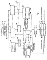
- FIG. 1 shows the functional diagram of the conveyor system according to the invention, in which material to be conveyed is transported in trolleys 10 via conveyor tracks 12 between transmitting and receiving stations.
- Each of the trolleys 10 has its own identification signal transmitter, which emits an identification signal that differs from those of the other carriages 10.
- the conveyor tracks 12 comprise a main conveyor track 14, which forms a main section or a loop, along which the trolleys 10 are moved to secondary conveyor tracks 16 which branch off from the main conveyor track 15.
- Both the main conveyor track 14 and the secondary conveyor tracks 16 each contain detector rails 18 and power supply rails 20.
- Each individual trolley 10 contains a motor, to which a supply voltage for driving the trolley 10 along the conveyor tracks 12 is supplied via the power supply rails 20.
- the detector rails 18 serve to detect the identification signal emitted by the respective identifier of the trolley 10 or to detect the presence of a trolley 10 on the respective conveyor track 12.
- the detector rails 18 can be arranged at predetermined locations along the conveyor tracks 12, so that with their help an approximate determination of the position of the trolleys 10 on the conveyor tracks 12 is possible.
- the conveyor system according to the invention also contains a number of switch devices 22 which are arranged at predetermined locations along the conveyor tracks 12.
- the switch devices 22 generally represent switching devices for the trolleys 10 between the main conveyor track 14 and the secondary conveyor tracks 16. However, the switch devices 22 can also be used to change the direction of the movement of the trolleys 10 along the main conveyor track 14.
- Each switch device 22 contains control rails 24 and a movable track section 26.
- control rails 24 of the switch devices 22, like the detector rails 18, contain rail sections for detecting the identification signals of the individual trolleys 10 and rail sections for detecting the presence of the trolleys 10.
- control rails 24 include further rail sections for stopping the trolleys 10.
- the movable track section 26 is slidably mounted between two positions relative to the main conveyor track 14 and the secondary conveyor tracks 16. In the first position, the movable track section 26 is aligned with the main conveyor track 14 between two connection points of the respective switch device 22. In the second position, the movable track section 26 is aligned with the secondary conveyor tracks 16 between two other connection points of the switch device 22.
- the connection points of the individual switch devices 22 are each assigned numbers 0 -3 such that the movable track section 26 is in a straight position, if it is aligned with the connection points 0 and 2 and is in the second (odd) position, if it is in line with the connection points 1 and 3.
- the conveyor system according to the invention contains a number of transmitting / receiving control units 28, which are assigned to corresponding transmitting and receiving stations for sending and receiving trolleys 10.
- Each transmitter / receiver control unit 28 is assigned a station address for its identification.
- Each transmission / reception control unit is usually arranged on a secondary conveyor track.
- the stations are used in two ways, namely as turning stations and as transfer stations. A turning station enables the movement of the trolleys 10 in each case on the same secondary conveyor track into and out of the respective station on the same secondary conveyor track 16.
- a pass-through station is characterized in that it allows the trolleys 10 to travel only in a single direction along the secondary conveyor track 16, so that a trolley 10 entering the pass-through station first leaves it.
- a pass-through station makes it possible to receive a trolley 10 at the same time and to send a further trolley.
- the switch devices 22 can be designed as end stations or can be connected to one, but preferably to two, stations for sending and receiving trolleys 10.
- the conveyor system according to the invention also contains a number of switch control units 30, of which one unit each has a switch device 22 in connection stands.
- the switch control units 30 serve to monitor and control the assigned switch devices 22 and their movable track sections 26 and to monitor the control rails 24 in the respective switch devices 22.
- a switch device 22 is controlled by the associated switch control unit 30, which moves the movable track section 26 via a motor with a drive device in the switch device 22 until the desired end position of the movable track section 26 is communicated to the switch control unit 30 by limit switches.
- each turnout device 22 contains a polarity reversal relay 32 controlled by the associated turnout control unit 30, in order to be able to reverse the polarity of the supply voltage on the sections of the power supply rails 20 in the region of the movable track section 26.
- Activation of the polarity reversal relay 32 causes a carriage 10 located on the movable track section 26 to move in one direction, while if the polarity reversal relay 32 is not actuated, the carriage 10 moves in the opposite direction.
- the associated switch control unit 30 receives input signals via the control rails 24.
- Each turnout control unit 30 can be connected to one or two transmit / receive control units 28, which in turn are connected to the station or stations to which the associated turnout device 22 sends or receives tram 10.
- the turnout control units 30 are each informed of the numbers of the connection points of the turnout devices 22 connected to the respective station via programmable address switches. Likewise, further programmable address switches are used to tell the switch control unit 30 whether a single station serves as a turning station or as a pass-through station.
- This information serves to determine the individual control steps for controlling the movement of a trolley 10 between a station and the switch device 22 connected to it.
- a central control unit 34 which is connected to each of the switch control units 30, is used for central control of the conveyor system according to the invention.
- the central control unit 34 contains a program-controlled processor and a memory as well as an input keyboard 36 for inputting data and information to the memory and a display unit 38 for the optical display of the desired information about the movement states of the trolleys 10.
- the central control unit 34 serves for the delivery of information to the Different switch control units 30, so that even with a large number of different trolleys 10 in the conveyor system, the movement of an individual trolley 10 from a transmitting station to a receiving station is made possible in the shortest possible time.
- the central control unit 34 In order to ensure exact control by the central control unit 34, this is programmed with a large amount of information about the configuration of the conveyor system according to the invention. A corresponding address is thus communicated to the central control unit 34 for each point control unit 30.
- the central control unit 34 For each of the associated switch devices 22, the central control unit 34 is given a number of a so-called standard input connection point (SE) and a so-called standard output connection point (SX).
- SE is generally the connection point of the switch device 22, which is located on the main traffic line of the tram 10 on the main conveyor track 14 and thus defines the starting or rest position of the movable track section 26.
- the standard output connection point (SX) is the connection point of the switch device 22, which points in the direction of the main traffic flow and on which all trams 10 die Exit switch device 22, unless another connection point is specified as an exit for the trolley 10 by an instruction.
- the central control unit 34 sends out a transmission information which is transmitted serially to each point control unit 30.
- the transmission information contains several bytes.
- the first byte contains the address of the switch control device 30 and the associated switch device 22, for which the following bytes are intended.
- the second byte contains the numbers of the connection points of the turnout device 22 addressed in byte 1, which form the standard input connection points or the standard output connection points.
- Byte 3 is used by the central control unit 34 to request information from the switch control units 33 and is also used to control certain functions associated therewith. Byte 4 is not used.
- Byte 5 contains the identification number of one of the trolleys 10 in the conveyor system according to the invention; With this identification number, the central control unit 34 informs the switch control unit 30 addressed in byte 1 about the identification number of the respective trolley 10, the path of which is to be controlled by the associated switch device. With byte 6, the central control unit 30 informs the switch control unit 30 addressed in byte 1 of the number of the connection point of the associated switch device 22, which is to serve as an output for the trolley 10 identified in byte 5 when the trolley leaves the switch device 22 again. Bytes 7 and 8 each serve to transmit status or control information to the switch control unit 30.
- each switch control unit 30, as already mentioned above, is connected to two transceiver control units 28 can stand, so that the information in byte 7 of one transmission / reception control unit 28 and the information in byte 8 of the other transmission / reception control unit 28 is to be assigned.
- an output control table 40 is stored in each switch control unit 30 in a memory, as shown in FIG. 3, with one storage location for each trolley 10 in the conveyor system is provided.
- Each storage location has a length of 8 bits, bits 4 and 5 identifying the connection point of the corresponding switch device 22 which serves as the exit for the relevant trolley 10.
- the junction 3 serves as the exit for the trolley 10 with the identification number n.
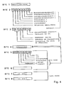
- FIG. 4 shows a data format for such a response signal.
- the response signal contains 8 bytes, the first byte containing the address of the answering point control unit 30 or the associated point control device 22.
- Byte 2 contains monitoring information at predetermined times or status information about the switch device 22.
- Byte 3 provides the central control unit 34 with information about the entry of a trolley 10 into the control area of the switch control unit 30.
- Byte 4 contains the identification number of a trolley 10, which in the case of detection of a trolley 10 together with byte 3 serves as information for the central control unit 34.
- Bytes 5 and 6 contain information for sending and / or receiving a trolley 10 in the area of the station, which is controlled by the corresponding switch control unit 30.
- byte 6 contains the destination or receiving address of the trolley 10 being sent, while byte 4 contains the identification number of this trolley.
- byte 4 is used together with either byte 3 or with bytes 5 and 6. Since the switch control unit 30 preferably controls two transmit / receive control units 28, the output signal contains two further bytes 7 and 8 instead of bytes 5 and 6 in order to provide the corresponding information for a second addressed transmit / receive control unit 28.
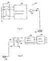
- Each trolley 10 in the conveyor system contains an identification signal transmitter 44 with a programmable address switch 42.
- the address switch 42 can be used to set a multiple-bit identification number so that, for example, with an 8-bit identification number, a total of 256 trolleys with different identification numbers are used in the conveyor system can find.
- the programmable address switch 42 is followed on the output side by a parallel / serial data converter 46, which converts the parallel output data of the programmable address switch 42 into serial data.
- a driver amplifier 48 is connected to the serial output of the parallel / serial data converter 46, the output signal of which has a level of approximately 6 V. This signal is fed to the control rail 24 via a diode 50 as soon as the trolley 10 comes into contact with this control rail 24 via a sliding contact.
- the control rail 24 is connected to a switch control device 30.
- the amplified serial output signal is transmitted from the identification signal generator 44 of the trolley 10 via the control rail 24 to a receiving device 52 in the switch control unit 30.
- the receiving device 52 contains a comparator device 54, 56, 58 with a differential amplifier 54, the inverting input (-) of which is connected to a voltage tap of a voltage divider consisting of two resistors 56 and 58 and is thus at a voltage of approximately 4 V. Since the output signal of the identifier 44 of the trolley 10 has a level of approximately 6 V, the voltage of 4 V at the inverting input (-) of the differential amplifier 54 serves as a threshold voltage.
- the serial output signal of the identification signal generator 44 is supplied via the control rail 24 to the non-inverting input (+) of the differential amplifier 54 and is amplified therein.
- a downstream serial / parallel data converter 60 the amplified serial signal is converted into a parallel signal which corresponds to the identification number of the trolley set with the programmable address switch 42 of the identification signal transmitter 44.
- the output of the serial / parallel data converter 60 is connected to a data memory 62, which supplies the identification number to the turnout control unit 30 on request.
- the serial / parallel converter 60 and the data memory 62 are connected on the control side to the switch control unit 30.
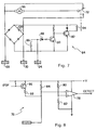
- each trolley 10 contains a drive control device 64 as shown in FIG. 7.
- the drive control device 64 contains a motor 66 which is electrically connected to the power supply rails 20 via sliding contacts.
- the power supply rails 20 consist of two adjacent contact rails 68 and 70, each carrying different voltage potentials, so that the motor 66 connected to the two contact rails 68 and 70 drives the trolley 10.
- the drive control device 64 also contains a switching relay 72 which, in a first switching position, connects the motor 66 to the voltage potential on the contact rail 70, so that a current flows through the current supply rails 20 through the motor 66 and drives the trolley 10. In the second switching position, the switching relay 72 short-circuits the motor connections in order to bring the motor 66 to a standstill and the trolley 10 to stop.
- each point control unit 30 contains a detector and control device 76, which is shown in more detail in FIG.
- the detector and control device 76 contains a threshold voltage detector 78, 80, 82 with a differential amplifier 78, the non-inverting input (+) of which is connected to the voltage tap of a voltage divider with the resistors 80 and 82.
- the threshold voltage present at this voltage tap is approximately 22 V.
- the inverting input (-) of the differential amplifier 78 is connected to the voltage tap of a further voltage divider, which consists of a resistor 84 and the control rail 24.
- the voltage signal at the inverting input (-) of the differential amplifier is 78 approximately 24 V and is therefore greater than the threshold voltage at the non-inverting input (+).
- the differential amplifier 78 outputs an output signal with a low level (low).
- the internal resistance 86 of the trolley 10 causes the voltage at the inverting input (-) of the differential amplifier 78 in the event that the value of the internal resistance 86 is approximately 8.2 kiloohms and the value of resistor 84 is about 100 kiloohms lowered to about 2 volts. The result of this is that a high signal level (high) is generated at the output of the differential amplifier 78, which indicates the presence of the trolley 10 on the control rail 24.
- the voltage on the control rail 24 also serves to control the trolley 10 and is supplied to the drive control device 64 of the trolley 10 via a Zener diode 88 (see FIG. 7) .
- a zener diode 88 is followed by a two-stage arrangement with a first transistor switch 90 and a second transistor switch 92, the second transistor switch 92 being in a current path with the excitation coil 94 of the switching relay 72.
- the voltage on the control rail 24 is approximately 2 V, so that the Zener diode 88, which has a Zener voltage of approximately 12 V, is in a non-conductive state.
- the detector and control device 76 of the switch control unit 30 shown in FIG. 8 also has a transistor 96 which is connected to the control rail 24 via a resistor 98.
- the switch control unit 30 In order to bring the trolley 10 to a standstill, the switch control unit 30 generates a stop signal which is fed to the base of the transistor 96 and controls the transistor 96 in a current-conducting state.
- the resistor 98 acts via the control rail 24 together with the internal resistor 86 of the drive control device 64 of the trolley 10 as a voltage divider which applies a voltage of approximately 19 V to the Zener diode 88 in the drive control device 64 of the trolley 10.
- the Zener diode 88 Since this voltage exceeds the Zener voltage (approximately 12 V) of the Zener diode 88, the Zener diode 88 is in a current-conducting state, so that the downstream first switching transistor 90 is also controlled in a current-conducting state and the second switching transistor 92 in a current-blocking state. This results in an interruption of the current flow through the excitation coil 94 of the switching relay 72, so that the switching relay 72 falls back into its second switching position, in which the motor connections of the motor 66 are short-circuited and, accordingly, the trolley 10 is at a standstill.
- a rectifier bridge circuit 100 which is connected to the contact rails 68 and 70 on the AC side, serves to supply power to the two-stage arrangement with the first switching transistor 90 and the second switching transistor 92 and the excitation coil 94 of the switching relay 72.
- the identification signal transmitters 44 of the various trolleys 10, the drive control devices 64 of the trolleys 10 or the detector and control devices 76 of the switch control units 30 must not influence one another. If at the exit of a Identifier 44 an output signal with a level of about 6 V is present, this signal has no influence on the conductivity of the Zener diode 88 in the drive control device 64, so that no current flows through the excitation winding 94 of the switching relay 72 and the motor 66 to the contact rails 68 and 70 remains switched.
- the diode 50 at the output of the transmitter 44 of the trolley 10 is controlled by the voltage of about 19 V on the control rail 24 in a non-conductive state, so that a possible by the output resistance of the Transmitter 44 causes the voltage at the zener diode 88 to drop below the zener voltage (approximately 12 V).
- the idle number of the trolley 10 cannot be detected while a trolley 10 is stationary in the area of a control rail 24. In the conveyor system according to the invention, however, it is not necessary due to the control to record the identification number of a trolley 10 which is at a standstill.
- the inverting input (-) of the differential amplifier 78 is at a voltage of 19 V, which is in any case lower than the voltage at the non-inverting input (+) of 22 V, so that the threshold voltage detector 78, 80, 82 receives a high level (high) as long as the trolley 10 is at a standstill and in contact with the control rail 24.
- FIG. 9 shows an exemplary embodiment of a switch device 22a.
- the switch device 22a shown has four connection points with the numbers 0 to 3.
- a trolley 10 which enters the switch device 22a at one of the four connection points 0 to 3, leaves it at one of the three other connection points on the way to its destination.
- the connection points 0 and 2 are each connected to sections of the main conveyor track 14, sections of a secondary conveyor track 16a and 16b being connected to the connection points 1 and 3.
- one connection point of the switch device 22a is defined as the standard input connection point (SE) and another connection point as the standard output connection point (SX). In the event that z. B.
- SE standard input connection point
- SX standard output connection point
- the switch device 22a further includes a movable track section 26a, which is positioned between the standard input connection point 0 and the standard output connection point 2. If a trolley 10 moves on one of the branching sections of the secondary conveyor track 16a or 16b, the movable track section 26a is moved into the position shown in broken lines.
- Control rails 24a which consist of a pair of detector rails 105 and a stop rail 104 lying between them, are arranged on the movable track section 26a.
- the stop rail 104 is used to stop a trolley 10 and to detect its presence.
- the detector rails 105 detect the presence of a trolley 10 on the movable track section 26a in the event that the trolley 10 is not in the area of the stop rail 104.
- the control rails 24a thus serve to notify the switch control unit 30 via the detector rail 105 when a trolley has entered the associated switch device 22a, and they also serve to bring the trolley 10 to a stop on the movable track section 26a via the stop rail 104.
- the movable track section 26a can be moved into its second position, shown in broken lines, in order to enable the conveyor carriage 10 to move further on the sections of the secondary conveyor track 16a and 16b.
- the sections of the main and secondary conveyor tracks connected to the connection points 0 to 3 of the switch device 22a likewise each have a stop rail 104 and a detector rail 106.
- the detector rails 106 are used, on the one hand, to detect the presence of a trolley 10 on the relevant conveyor track by the downstream detector and control device 76 of the associated point control unit 30.
- the receiving device 52 of the point control unit 30 reads in the identification number of the trolley 10 via the detector rail 106.
- the stop rail 104 like the corresponding stop rail 104 of the movable track section 26a, serves for detecting the presence and for stopping a trolley 10.
- each conveyor track in the area of the respective connection point 0 to 3 of the switch device 22a has a stop rail 104 and a detector rail 106 it is possible to prevent the transport of a trolley 10 into the switch device 22a as long as a trolley 10 is already in the switch device 22a; the turnout control unit 30 is informed at all times of the presence and the identification numbers of the trolleys 10 ready to enter or leave the turnout device 22a.
- the polarity reversal relay 32 (cf. FIG. 1) serves to set the desired voltage polarity on the power supply rails 20a of the movable track section 26a such that the trolley 10 can leave the switch device 22a in different directions, namely on the section 16a or on the section 16b.
- the exemplary embodiment of the conveyor system shown schematically in FIG. 10 serves to explain the functioning of the conveyor systems according to the invention.
- six stations A to F are provided for sending and / or receiving trolleys 10; each transmission / reception station A to F is assigned a transmission / reception control unit 28a to 28f.
- the conveyor system also contains nine switch devices 22a to 22i, each of which is connected to its own switch control unit 30a to 30i for controlling and monitoring the sequence of movements of the trolleys 10.
- the switch devices 22 serve different functions.
- the switch devices 22e and 22i are thus exclusively intended to divert the direction of travel of the trolleys 10 at each end of the main conveyor track 14.
- the main conveyor track 14 consists of two parallel directional tracks, along which the trolleys 10 travel in opposite directions. Each trolley 10 that enters one of the two switch devices 22e or 22i is transferred from one directional track to the other directional track of the main conveyor track 14 with the aid of the respective movable track section 26e or 26i.
- the switch device 22a, 22f and 22g serve u. a. to redirect the trolley 10 to a turning conveyor track 16a, 16d or 16e.
- the trolley 10 can be bidirectionally either from the corresponding switch device 22a, 22f or 22g to a turning / receiving station A, D or E or in the opposite direction from one of the transmitting / receiving stations A, Drive D or E to the corresponding switch device 22a, 22f or 22g.
- the switch device 22a can transport trolley 10 both to the transmitting / receiving station A and can receive from it.
- the switch device 22f serves both for sending trolleys 10 to the transmitting / receiving station D and for receiving the trolleys 10 from this station D.
- station D serves to temporarily park certain trolleys 10.
- the standard exit connection point (SX) of the switch device 22f is assigned to the connection point 2 connected to the station D.
- SX standard exit connection point
- the turnout device 22g serves to send or receive the trolleys 10 to and from the transmitting / receiving station E via the turning conveyor track 16e.
- the conveyor system shown in FIG. 10 also contains secondary conveyor tracks 16b, 16c and 16f, which only allow conveyor car transport in one direction.
- These secondary conveyor tracks 16b, 16c and 16f serve to convey the trolleys 10 from the respective switch devices 22a, 22d and 22h in one direction to transmitting / receiving stations, so that they receive the trolleys 10 from this one direction Stations that can only forward trams in the same direction.
- the switch device 22a which, as already described, is connected to the station A via the turning conveyor track 16a, is additionally connected to the transmitting / receiving station B for receiving the trolleys 10 via a section of the secondary conveyor track 16b.
- the switch device 22d enables the transport of the trolleys 10 to the station C via the secondary conveyor track 16c, and the switch device 22h is connected via a section of the secondary conveyor track 16f to the transmitting / receiving station F, which receives the conveyor cars 10 from the switch device 22h.
- the switch devices 22c and 22g are each connected to the stations B and F via sections of the secondary conveyor tracks 16b and 16f, while the switch device 22d both for reception and is also connected to the station C for sending the trolleys 10 via the secondary conveyor track 16c.
- the switch device 22b is furthermore arranged, which has two simultaneously movable track sections 22b and 22b 'lying parallel to one another.
- the two movable track sections 22b and 22b ' are slidably mounted between the connection points 0 to 3 of the switch device 22b in such a way that the track section labeled 26b can be moved from a position aligned with the connection points 1 and 3 to a position between the connection points 0 and 2 and the other track section 26b 'is simultaneously shifted from a position between the connection points 0 and 2 into the position shown in broken lines.
- this switch device 22b it is possible to divert a trolley 10 from one directional track of the main conveyor track 14 to the other directional track, so that there is the possibility of the route and the Shorten the travel time of a tram 10 from one station to another station. If, for example, a trolley 10 is dispatched from station A, to which station E is assigned as the destination address, where trolleys 10 entering the movable track section 26b 'between the connection points 1 and 3 of the point device 22b are moved between the connection points 0 and 2, so that the trolley 10 can reach the station E from this position via the switch device 22g. Otherwise, the trolley 10 would have had to pass through switch devices 22c, 22d, 22e and 22f on its way to station E.
- switch directions 22e and 22i at the ends of the main conveyor track 14 it should be pointed out that it is also possible to guide the direction tracks of the main conveyor track 14 into one another at their ends in a semicircle, so that the two direction tracks of the main conveyor track 14 are one in this way form a closed loop. In this case, the two switch devices 22e and 22i can be omitted. Furthermore, it is also not necessary for the two directional tracks of the main conveyor track 14 to run parallel to one another, as shown in FIG. 10; In accordance with the respective spatial requirements, it may be more advantageous to loop the directional tracks at a large distance from one another.
- the switch devices 22 serve to connect secondary conveyor tracks to the main conveyor track 14.
- control and monitoring of the conveyor system according to the invention there are no restrictions.
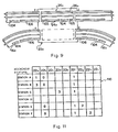
- a conveyor path table 110 is created in the memory of the central control unit 34. With reference to the exemplary embodiment of the conveyor system according to the invention shown in FIG. 10, such a conveyor path table 110 is shown in FIG.
- the conveyor path table 110 contains all the transmitting or receiving stations A to F and all the switch devices 22a to 22i of the conveyor system according to FIG. 10, the rows and the switching devices 22a to 22i the columns of the conveyor path table 110 being assigned to the transmitting / receiving stations A to F.
- the conveyor path table 110 arises from the point of view of determining the shortest possible conveyor path for the trolley 10 on the way to its receiving station, including the switch devices 22 with which the trolley 10 comes into contact and whose connection point serving as an exit for the trolley 10 is other than is the respective standard output connector (SX).
- the content of the conveyor path table 110 is independent of the station from which the conveyor truck 10 was sent.
- a trolley 10 to which station B (see FIG. 10) is assigned as the destination address must instead leave the switch device 22f instead of at the standard exit connection point 2 at the connection point 1, with the corresponding movable track section 26f by the associated switch control device 30f is moved into an aligned position with the connection point 1. If this trolley 10 comes from the right into the area of the switch device 22b, the associated switch control unit 30b will preferably determine the connection point 0 as the output for the trolley 10 and not the standard exit connection point 3.
- the trolley 10 with the station B as the destination address Switch device 22a does not leave the standard exit connection point 2, but instead the trolley 10 is controlled to leave the switch device 22a by means of the movable track section 26a in a position aligned with the connection point 3.
- the associated switch control device 30 controls the respective movable track section 26 such that the trolley can leave the respective switch device 22 at its standard exit connection point (SX).
- station B contains a trolley 10 to be sent to station E.
- the user of the conveyor system first enters the address of the receiving station E into the transmitting / receiving control unit 28b assigned to the transmitting station B. This address information is received by the switch control device 30a, via which the transceiver control unit 28b is connected to the central control unit 34. Is the receiving station E for the trolley 10th Ready to receive, the central control unit 34 transmits corresponding information to the switch control unit 30a for sending the trolley 10.
- the trolley 10 leaves the transmitting station B, its identification number is detected via the detector rail 106 of the secondary conveyor track 16b indicated by a point in FIG.
- the identification number is transmitted to the central control unit 34 together with the transmission address of the transmission station B via the switch control unit 30a. It is further assumed that the conveyor system shown in FIG. 10 is capable of controlling and monitoring 16 individual trolleys 10 and that the trolley 10 sent to the receiving station E has the identification number 13.
- the central control unit 34 now accesses the conveyor path table 110 stored in its memory in order to determine the desired conveyor path of the trolley 10 with the identification number 13 to the station E.
- the conveyor path table 110 contains the instruction to assign the trolley 10 in the switch device 22b to the connection point 0 as an output. This instruction is communicated to the switch control unit 30b by the central control unit 34.
- the switch control units 30f and 30e receive the instruction from the central control unit 34 based on the conveyor path table 110 to control the associated switch devices 22f and 22g in such a way that the trolley 10 with the identification number 13 leaves the connection points 1 and 2, respectively.
- the switch control unit 30g thus contains the information that the trolley 10 with the identification number 13 reaches the receiving station E when it leaves the switch device 22g at its junction 2. On its way to the station E, the trolley 10 with the identification number 13 will additionally pass through the switch devices 22c, 22d and 22e, the associated switch control units 30c, 30d and 30e determining the respective standard exit connection point (SX) as the exit for the trolley 10.
- SX standard exit connection point
- the point control units 30b, 30f and 30g store in the output control table 40 (see FIG. 3) stored in their memories in the row for the trolley 10 with the identification number 13 the respective number as the output for the trolley 10 serving connection point of the associated switch devices 22b, 22f and 22g.
- a substitute code word is stored instead, which designates the respective standard exit connection point of the relevant switch device 22.
- the switch control unit 30a When the trolley 10 with the identification number 13 leaves the transmitting station B, the switch control unit 30a outputs a response signal containing the identification number 13 of the trolley 10 to the central control unit 34. As already shown in FIG. 4, this response signal contains a number of information bytes, of which byte 4 the identification number 13 of the trolley 10, byte 6 the address of the receiving station E and byte 1 the address of the switching device 22a or the one assigned to it and the response signal sending switch control unit 30a contains. If the trolley 10 with the identification number 13 reaches the switch device 22c, the assigned switch control unit 30c accesses the output control table 40 stored in it and takes from it the information that the tram 10 located in the switch device 22c has the standard exit connection point 2 as an exit to the main conveyor track 14 can be assigned.
- This determination is made by querying the identification bit 6 in the line for the trolley 10 with the identification number 13 of the output control table 40, a value 0 of the identification bit meaning that the standard exit connection point (SX) is provided as the output for the trolley 10.
- the switch control unit 30c 4 in turn sends a transmission information to the central control unit 34 with the data format shown in FIG. 4, which in bytes 3 and 4 informs the central control unit 34 that the point control unit 30c identified in byte 1 has detected the presence of a trolley 10 with the identification number 13 .
- the switch control units 30d and 30e control the switch devices 22d and 22e assigned to them in such a way that the trolley 10 with the identification number 13 leaves both switch devices 22d and 22e via their standard exit connection points 2 and 0, respectively.
- the associated switch control units 30f and 30b determine from the output control tables 40 stored in them that the tram 10 with the identification number 13 is not the respective standard exit point (SX), but the connection point 1 of the switch device 22f or the connection point 0 the switch device 22b serves as an output.
- the switch control units 30f and 30b control the movable track sections 26f and 26b of the switch devices 22f and 22b so that they are aligned with the connection points intended for outputs.
- the output control table 40 in the memory of the associated switch control unit 30g for the identification number 13 indicates that the relevant trolley 10 is to be rerouted to the connection point 2.
- the central control unit 34 Before the trolley 10 with the identification number 13 enters the switch device 22g, it is identified via the detector rail 106 on the section of the main conveyor track 14 connected to the connection point 3 and the arrival of the trolley 10 is communicated to the central control unit 34.
- the central control unit 34 has the entire movement sequence of the trolley 10 with the identification number 13 is monitored with the aid of the transmission information received and given by it in the data formats indicated in FIG. 2 or in FIG. 4.
- the central control unit 34 terminates the execution of the program part currently running in it and gives the instructions to the switch control units 30b, 30f and 30g, in the respective output control tables 40 the to replace the respective exit for the trolley 10 with the identification number 13 by corresponding information values which denote the standard exit connection points (SX) of the respectively assigned switch devices 22b, 22f and 22g.
- SX standard exit connection points
- the control sequence for the movement of two different trolleys 10 to and from a common switch device 22 is described below with the aid of a further example. It is assumed here that the two trolleys 10 have the identification numbers 7 and 12 and move together on the main conveyor track 14 in the direction of the switch device 22a. It is further assumed that the tram 10 with the identification number 7 is assigned the destination address of the station C and that the trolley 10 with the identification number 12 has the destination A as its destination, which is connected to the switch device 22a via the turning conveyor track 16a. Finally, it is assumed that the trolley 10 with the identification number 7 moves in front of the trolley 10 with the identification number 12 on the main conveyor track 14.
- the detector and control device 76 in the switch control unit 30a detects the presence of the trolley 10 via the stop rail 104 (see FIG. 9) with the Identification number 7 immediately in front of the connection point 0 and generates a stop signal for the stop rails 104 of those conveyor track sections which are connected to the other connection points of the switch device 22a serving as an input.
- the switch control unit 30a generates a stop signal on the stop rail 104 of the section of the turning conveyor track 16a connected to the connection point 1.
- the stop signal on the stop rail 104 prevents further trolleys 10 from entering the switch device 22a as long as the trolley 10 with the identification number 7 is in the switch device 22a. In the case of the switch device 22a, this has the consequence that each trolley 10 which is emitted by the station A is stopped in front of the connection point 1 of the switch device 22a.
- the associated switch control unit 30a also generates a stop signal for the stop rail 104 just passed by the trolley 10 with the identification number 7, so that the subsequent trolley 10 with the identification number 12 is stopped on the stop rail 104 until the trolley 10 with the identification number 7 has left the switch device 22a.
- the receiving device 52 in the switch control unit 30a reads in the identification number 7 emitted by the transmitting device 44 of the trolley 10 via the detector rail 106.
- the switch control unit 30a determines from the one stored in it Output control table 40 that connection point which is intended as an output for the tram 10 with the identification number 7.
- the standard exit connection point (SX) of the switch device 22a serves as an exit.
- This information results from the identification bit 6 in the output control table 40, which indicates with a 0 as an information value that the corresponding trolley 10 is assigned the standard exit connection point (SX) as an exit for leaving the switch device 22a. Since the movable track section 26a of the switch device 22a is in its rest position between the connection points 0 and 2, the trolley 10 with the identification number 7 passes through the switch device 22a without stopping and leaves it at the connection point 2 on the way to its destination station C.
- the switch control unit 30a detects, via the detector rail 106 of the section of the main conveyor track 14 connected to the connection point 2 of the switch device 22a, the time at which the trolley 10 with the identification number 7 has left the switch device 22a and thereby recognizes the control of the trolley 10 with the identification number 7 in the area of the switch device 22a as finished.
- the switch control unit 30a then interrogates the stop rails 104 of the conveyor track sections connected to the connection points serving as inputs for the presence of further trolleys 10. In the example dealt with here, the switch control unit 30a detects the presence of the further conveyor carriage 10 with the identification number 12 on the stop rail 104 of the section of the main conveyor track 14 which is connected to the connection point 0.
- the switch control unit 30a now cancels the stop signal lying on the stop rail 104, so that the trolley 10 with the Identification number 12 continues its journey via junction 0 to the movable track section 26a of the switch device 22a.
- the trolley 10 with the identification number 12 passes over the detector rail 106 upstream of the junction 0 on the main conveyor track 14, the switch control unit 30a - as already described above for the trolley 10 with the identification number 7 - the stop rail 104 located in front of the detector rail 106 with a
- the stop signal is applied and the identification number 12 of the relevant trolley 10 is read in via the detector rail 106.
- the point control unit 30a determines from the output control table 40 stored in it the connection point which is intended as the output for the trolley 10 with the identification number 12.
- the junction 1 serves as an exit for the trolley 10. It is therefore necessary to move the trolley 10 to the junction 1 using the movable track section 26a to postpone. As soon as the trolley 10 entering the switch device 22a with the identification number 12 reaches the stop rail 104 on the movable track section 26a, the presence of the trolley 10 is detected by the switch control unit 30a and a stop signal for stopping the trolley 10 is emitted. The switch control unit 30a then controls the movable track section 26a from the position aligned with the connection points 0 and 2 into a new position aligned with the connection points 1 and 3 and shown here in broken lines.
- the switch control unit 30a by actuating the polarity reversal relay 32, reverses the polarity of the supply voltage on the power supply rails 20a of the movable track section 26a, so that after the stop signal on the stop rail 104 has been removed, the trolley 10 with the identification number 12 the switch device 22a leaves at its junction 1.
- the trolley 10 travels over the detector rail 105 of the movable track section 26a and subsequently over the detector rail 106 and the stop rail 104 of the section of the turning conveyor track 16a connected to the connection point 1.
- the switch control unit 30a detects via the stop rail 104 the time at which the trolley 10 with the identification number 12 leaves the switch device 22a and thereby recognizes the control of the trolley 10 with the identification number 12 in the area of the switch device 22a as finished. Thereafter, the switch control unit 30a controls the movable track section 26a back to its rest position between the connection points 0 and 2 and ends the activation of the polarity reversal relay 32, so that the direction of travel for the trolleys 10 on the movable track section 26a again runs from left to right in the direction of the default exit port (SX) of the switch 22a is set. The turnout control unit 30a then again interrogates the stop rails 104 of the conveyor track sections connected to the connection points serving as inputs for the presence of further conveyor carriages 10, in order to control them one after the other as described above by the turnout device 22a.
- the central control unit 34 provides the evaluation of the by the transmission / reception control unit 28a Transmission information transmitted to the central control unit 32 via the switch control unit 30a (see FIG. 4) for so long until the central control unit 32 has determined that the trolley 10 ready for dispatch in station A is determined next in the sequence of the trolleys 10 to be controlled by the switch device 22a.
- Another control function of the central control unit 34 serves to prevent the sending of additional trolleys 10 into the conveyor system if the central control unit 34 has been informed by the user of a maximum permissible number of trolleys 10 rotating in the conveyor system. In this case, the central control unit 34 rejects all transmission information sent by the transmission / reception control units 28, which contains a request to send trolleys 10.
- the central control unit 34 is equipped with a large number of further monitoring functions.
- a first monitoring function relates to the detection of the average time that a trolley 10 needs to travel from one switch device 22 to another switch device 22.
- the central control unit 34 determines whether a trolley 10 requires an above-average travel time between two switch devices 22.
- the central control unit 34 stores information about the travel sequences of the individual trolleys 10 in its memory. This information includes, in particular, the address of the sending and receiving stations assigned to the respective trolley 10, the identification numbers of the individual trolleys 10 and the elapsed travel time of the trolley 10.
- the central control unit 34 contains for each Trams 10 each have a counter is reset each time the trolley 10 leaves a switch device 22. The detection of the moment at which a trolley 10 leaves a switch device 22 has already been described in detail above.
- the central control unit 34 constantly compares the counter reading of each individual counter with a predetermined time value. If the counter reading exceeds the specified time value, the central control unit 34 issues an error message together with the identification number of the respective trolley 10 for the user of the conveyor system.
- the predefined time value is preferably selected to be somewhat longer than the time period which a trolley 10 requires on its way between the most distant switch devices 22 or the detector rails 18 or the control rails 24.
- An extension of the monitoring function of the central control unit 34 described above relates to the determination of the approximate position of the respective trolley 10 in the conveyor system at the point in time at which the counter reading the predetermined time value in connection with the detection of the travel time of the trolley 10 between two switch devices 22 described above exceeds. This is done in that the central control unit 34 additionally stores the address of the last switch device 22 that the trolley 10 passed through before the error message occurred. On the basis of this additional information, the user of the conveyor system is able to find the relevant conveyor 10 in the conveyor system in the event of a fault.
- the dwell time of each individual trolley 10 in the conveyor system is recorded from a transmission station from the time of its dispatch.
- the central control unit 34 contains for everyone to be monitored Trams 10 each have a further counter, which is reset as soon as the trolley 10 in question leaves the transmitting station. If the dwell time of the trolley 10 in the conveyor system reaches a predetermined maximum duration, then the central control unit 34 causes a further error message to be issued.
- the predefined maximum duration is chosen to be slightly longer than the maximum expected time that a trolley 10 needs on its way from a transmitting station to a receiving station when the conveyor system is functioning properly.
- This second monitoring function is used to record possible errors that would otherwise go undetected.
- a trolley 10 with the identification number 13 is sent from station B to station E. It is assumed that, for some reason of error, the soft device 22g does not assign the trolley 10 the connection point 2, but the standard exit connection point 0 as the output.
- the trolley 10 with the identification number 13 would constantly circulate on the main conveyor track 14 through the switch devices 22a, 22b, 22g, 22h and 22i, and at each of these switch devices the position of the trolley 10 would be detected by the central control unit 34. In this fault case, after some time the duration of the trolley 10 with the identification number 13 in the conveyor system exceeds the predetermined maximum duration, so that the central control unit issues an error message together with the identification number 13 for the user of the conveyor system.
- the central control unit 34 advantageously contains a program part which causes the trolley 10 to be controlled back into its transmitting station.
- the return of the respective trolley 10 can be carried out very easily because the central control unit 34 contains in its memory the addresses of the transmitting stations from which the individual trolleys 10 have been sent to the conveyor system.
- the central control unit 34 contains in its memory the addresses of the transmitting stations from which the individual trolleys 10 have been sent to the conveyor system.
- a third monitoring function of the central control unit 34 relates to the recording of the total length of stay of all trolleys 10 in the conveyor system.
- the total time of stay corresponds to the sum of all times of stay of the individual trolleys 10.
- the user of the conveyor system receives all the necessary information about the degree of utilization of the conveyor system according to the invention.
- a further monitoring function of the central control unit 34 relates to the control of trolleys 10 in the event that the receiving station assigned to them in each case via the destination address is overcrowded with other trolleys 10 and is therefore no longer ready to receive.
- each station is assigned a rail, which is connected to the switch control unit 30 associated with the station. If a trolley 10 is located on such a rail, this indicates to the respective switch control unit 30 that the station in question can no longer accommodate any further trolleys 10. In this case, the station in question blocks the access of further trolleys 10 and redirects them. The trams 10 thus redirected continue their journey and, if necessary, reach their desired destination address.
- the central control unit 34 receives the number of trolleys 10 diverted at the overcrowded station via the respective switch control unit 30 Central control unit 34 compares the current number of redirected trolleys 10 with a predetermined numerical value, and if this numerical value is exceeded, central control unit 34 can, for example, arrange for further trolleys 10 to be sent back to their respective transmitting station on the way to the overcrowded station.
- the central control unit 34 carries out an additional monitoring function which serves to provide a predetermined number of trolleys 10 in each station of the conveyor system. For this purpose, the central control unit compares the number of trolleys currently in a station with the predetermined minimum number of trolleys 10 in each station. If the current number of trolleys 10 in the station is less than the predetermined number, the central control unit 34 automatically sends a corresponding number of further trolleys 10 to the station.
- the conveyor system according to the invention can have a storage station from which the trolleys 10 required to fill up the other stations can be called up.
- the central control unit 34 of the conveyor system provides for the display of important information relating to the individual trolleys 10 controlled in the conveyor system travel via a display unit 38 (cf. FIG. 1).
- the input keyboard 36 allows the user to select the information to be displayed.
- This information includes the display of all the trolleys 10 that are in motion with their respective identification numbers and their respective sending and receiving stations. Further information of this type relates to the display of the travel times of the individual trolleys 10, the indicators of the current location of the individual trolleys 10 and the display of the respective operating states of the individual stations and switch devices 22.
- the information about the operating states includes e.g. B. the display of whether a turning point to the central control unit 34 to send a tram 10, or whether the entry and exit of the tram 10 via the corresponding standard input connection points (SE) or standard output connection points (SX) of the switch devices 22.
- SE standard input connection points
- SX standard output connection points
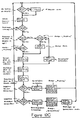
- FIGS. 12A to 12D show flow diagrams of the control and monitoring functions of the central control unit 34 described above.
- the invention relates to a computer-controlled conveyor system with a number of trolleys for conveying various types of conveyed goods from transmitting stations to receiving stations.
- the conveyor system according to the invention has a main conveyor track, along which the trolleys are moved between individual stations. Secondary conveyor tracks branch off from the main conveyor track, on which the trolleys are transported between the main conveyor track and sending or receiving stations.
- Sectional switch devices are provided along the main conveyor track.
- Each switch device has four connection points and a movable track section.
- the four connection points form connection points for sections of the main conveyor track and / or the secondary conveyor track, with which the movable track section can be brought into an aligned position.
- the movable track section serves as a link between the main conveyor track and a secondary conveyor track. For this purpose, the movable track section can be moved into two positions, wherein it forms part of the main conveyor track in the first position and forms part of the secondary conveyor track in the second position.
- Each turnout device is connected to a turnout control unit.
- the individual turnout control units are in turn connected to a central control unit which carries out control and monitoring functions in accordance with the invention.
- Transmit / receive control units which are assigned to the respective secondary conveyor tracks and are arranged at the various transmit and receive stations, are connected to the central control unit via the individual switch control units.
- Each trolley is assigned its own identification signal transmitter for controlling and monitoring the movement of the large number of trolleys by the central control unit.
- the user of the conveyor system enters into the central control unit a receiving address for the transmitting / receiving station to which a conveyor car is to be sent via the main conveyor track.
- the central control unit With these two pieces of information, namely the receiving address (or destination address) and the trolley identifier, the central control unit is able to control the movement of the trolley along a desired conveyor track.
- the associated point control unit uses the information received from the central control unit and spoken by the point control unit to assign the movable track section of the point device to the desired position, so that the trolley can find its way along the desired or selected conveyor track can continue.
- the point control unit determines the tram identifier and uses it to determine the desired position of the movable one Track section.
- the switch control unit controls the movable track section into a position in which the trolley is moved onto the secondary conveyor track and can reach the receiving station addressed by the receiving address.
- the central control unit In addition to the function of controlling the movement of the trolleys from the transmitting stations to the receiving stations with the aid of the trolley identifier, the central control unit with the associated switch control units provides a large number of other additional functions which are important for the function of the conveyor system according to the invention.
- the central control unit also serves to prevent trolleys from being sent from a transmitting station if the addressed receiving station is not available.
- the central control unit also automatically changes the specified route during the movement of a trolley if the receiving station is not ready to receive.
- the central control unit also serves to monitor the approximate position of each individual trolley during its movement along the conveyor track. There is also the possibility of recording the elapsed time of a trolley moving in the conveyor system according to the invention since it was sent from a transmitting station.
- the duration of use of each individual trolley in the conveyor system according to the invention can be determined accordingly.
- Another control function of the central control unit is to provide a sufficient number of trolleys for each individual station.
- empty trolleys or trolleys, the identification of which cannot be determined, are controlled by the central control unit at specified stations.
- the computer-controlled conveyor system according to the invention enables efficient transportation of each of many trolleys to the desired destination.
- the identifier can thus be attached to the trolley with little effort and can easily replace actuators for controlling the movement of the trolley.
- the conveyor system according to the invention enables a display and monitoring of the movement of the various trolleys with different target directions, so that the user of the conveyor system is informed about the targets of the various trolleys, their current position and their conveyance in the conveyor system.
Abstract
Description
Die Erfindung betrifft ein Verfahren gemäß dem Oberbegriff des Patentanspruches 1 sowie eine Förderanlage zur Durchführung dieses Verfahrens gemäß dem Oberbegriff des Anspruches 14.The invention relates to a method according to the preamble of
In relativ großen Bürogebäuden oder Krankenhäusern stellt sich die Aufgabe, verschiedenartiges Fördergut mit möglichst hoher Effizienz von einer Stelle zur anderen Stelle zu befördern. Hierzu dienen in bekannter Weise Förderanlagen, bei denen der Transport in spurgebundenen Förderwagen erfolgt. Die Förderwagen weisen Förderbehälter zur Aufnahme des Fördergutes auf, welches mit Hilfe der Förderwagen von einer neben einem Abschnitt der Förderspur angeordneten Station (Sendestation) zu einer neben einem anderen Abschnitt der Förderspur gelegenen anderen Förderstation (Empfangsstation) befördert wird.In relatively large office buildings or hospitals, the task is to transport various types of goods from one place to another with the greatest possible efficiency. Conveyor systems are used for this in a known manner, in which the transport takes place in track-bound trolleys. The trolleys have conveying containers for receiving the material to be conveyed, which is conveyed with the aid of the trolleys from a station (transmitting station) arranged next to a section of the conveying track to another conveying station (receiving station) located next to another section of the conveying track.
Es sind Förderanlagen bekannt, bei denen die Bewegung von Förderwagen entlang einer Hauptförderspur gesteuert wird, von der Nebenförderspuren zu einzelnen Stationen abzweigen. Dabei wird jedem der Förderwagen jeweils eine Zieladresse zugeordnet, die bei Bewegung des jeweiligen Förderwagens entlang der Hauptförderspur an den Abzweigpunkten der einzelnen Nebenförderspuren von der Hauptförderspur abgefragt wird, um so festzustellen, ob der Förderwagen die adressierte Zielstation erreicht hat.Conveyor systems are known in which the movement of trolleys along a main conveyor track is controlled, from which secondary conveyor tracks branch off to individual stations. Each of the trolleys is assigned a destination address, which is queried when the respective trolley moves along the main conveyor track at the branch points of the individual sub-conveyor tracks from the main conveyor track, in order to determine whether the trolley has reached the addressed destination station.
Es ist weiterhin eine rechnergesteuerte Förderanlage bekannt, bei der ein zentraler Hauptprozessor in Verbindung mit jedem Förderwagen mit Förderbehältern steht. Die Förderwagen halten ihrerseits jeweils einen Mikroprozessor, der mit dem Hauptprozessor in einem Datenaustausch steht und die Speicherung einer dem zugeordneten Förderwagen zugewiesenen Zieladresse ermöglicht; auf diese Weise ermöglicht die bekannte Förderanlage, den Transport des Fördergutes zu seiner Zieladresse zu steuern.A computer-controlled conveyor system is also known, in which a central main processor is connected to each conveyor car with conveyor containers. The trolleys in turn each hold a microprocessor, which is in a data exchange with the main processor and enables the storage of a destination address assigned to the assigned trolley; In this way, the known conveyor system enables the transport of the goods to be conveyed to their destination to be controlled.
Nach einem weiteren bekannten System (US-A-3 908 113) ist jeder Förderwagen mit einem Strichcode zur Identitätskennung versehen, der von über die Anlage verteilt angeordneten Leseeinrichtungen gelesen werden kann. Dabei wird beim Absenden eines Förderwagens eine der Empfangsstation zugeordnete Zieladresse zusammen mit der Kennungsnummer an eine Zentralsteuereinheit übertragen. Fährt der Förderwagen in eine Weiche ein, der eine Leseeinheit zugeordnet ist, so wird die Kennungsnummer über die Leseeinheit aufgenommen und wird über die Zentralsteuereinheit entsprechend der Zieladresse ein Steuersignal an die Weiche gegeben, um den Förderwagen entsprechend der zugeordneten Zieladresse zur Empfangsstation zu steuern. Ein solches System gibt aber keine ausreichende Abfragesicherheit, weil es infolge Beschädigungen oder Verschmutzungen an den Strichcodes zu Fehlerkennungen kommen kann. Auch ist bei einem einmaligen Vorbeifahren eines Strichcodes an einer optischen Leseeinheit keine ausreichende Abfragesicherheit gegeben. Schließlich sind aufwendige Verkehrssteuerungen erforderlich, um Fehlerkennungen bei Stillsetzen eines Förderwagens auszuschließen.According to a further known system (US-A-3 908 113), each trolley is provided with a bar code for identity identification, which can be read by reading devices arranged over the system. When a trolley is sent, a destination address assigned to the receiving station is transmitted to a central control unit together with the identification number. If the trolley moves into a switch which is assigned a reading unit, the identification number is recorded via the reading unit and a control signal is sent to the switch according to the target address in order to control the trolley according to the assigned target address to the receiving station. However, such a system does not provide sufficient security against queries, because damage or contamination of the bar codes can lead to error detections. Even if a bar code passes the optical reading unit once, there is no sufficient security against interrogation. Finally, complex traffic controls are required in order to rule out error detection when a tram is stopped.
Der Erfindung liegt die Aufgabe zugrunde, ein Verfahren anzugeben, das eine zuverlässige Steuerung der Bewegungen einer Vielzahl von Förderwagen in einer Förderanlage ermöglicht.The invention has for its object to provide a method that enables reliable control of the movements of a plurality of trolleys in a conveyor system.
Diese Aufgabe wird erfindungsgemäß für das Verfahren durch die im kennzeichnenden Teil des Anspruches 1 enthaltene Merkmale gelöst. Für die Förderanlage wird die Aufgabe durch die im kennzeichnenden Teil des Anspruches 14 enthaltenen Merkmale gelöst. Zweckmäßige Weiterbildungen sind in den Unteransprüchen angegeben.This object is achieved for the method by the features contained in the characterizing part of
Nachfolgend wird ein Ausführungsbeispiel der Erfindung anhand der Zeichnung beschrieben. Darin zeigen
Figur 1- ein Funktionsdiagramm eines Auführungsbeispiels der erfindungsgemäßen Förderanlage,
Figur 2- das Datenformat einer Sendeinformation von der Zentralsteuereinheit zu den Weichensteuereinheiten,
Figur 3- eine Ausgangssteuertabelle für eine Weichensteuereinheit,
Figur 4- ein Datenformat für ein Antwortsignal von einer Weichensteuereinheit zu der Zentralsteuereinheit,
Figur 5- ein Schaltbild eines Kennungssignalgebers in einem Förderwagen,
Figur 6- ein Schaltbild einer Empfangseinrichtung einer Weichensteuereinheit,
- Fig. 7
- ein Schaltbild einer Antriebsteuereinrichtung eines Förderwagens,
- Fig. 8
- eine Detektor- und Steuereinrichtung einer Weichensteuereinheit,
- Fig. 9
- den schematischen Aufbau einer Weicheneinrichtung,
- Fig. 10
- einen schematischen Aufbau der erfindungsgemäßen Förderanlage mit neun Weicheneinrichtungen und sechs Stationen,
- Fig. 11
- eine Förderwegtabelle, wie sie in einem Speicher der Zentralsteuereinheit der erfindungsgemäßen Förderanlage entsprechend Fig. 10 gespeichert ist, und
- Fig. 12A bis 12D
- Flußdiagramme von Steuer- und Überwachungsfunktionen der erfindungsgemäßen Förderanlage.
- Figure 1
- 2 shows a functional diagram of an exemplary embodiment of the conveyor system according to the invention,
- Figure 2
- the data format of a transmission information from the central control unit to the switch control units,
- Figure 3
- an output control table for a switch control unit,
- Figure 4
- a data format for a response signal from a switch control unit to the central control unit,
- Figure 5
- 1 shows a circuit diagram of an identification signal transmitter in a tram,
- Figure 6
- 1 shows a circuit diagram of a receiving device of a switch control unit,
- Fig. 7
- 1 shows a circuit diagram of a drive control device of a trolley,
- Fig. 8
- a detector and control device of a switch control unit,
- Fig. 9
- the schematic structure of a switch device,
- Fig. 10
- 1 shows a schematic structure of the conveyor system according to the invention with nine switch devices and six stations,
- Fig. 11
- a conveyor path table, as it is stored in a memory of the central control unit of the conveyor system according to FIG. 10, and
- Figures 12A to 12D
- Flow charts of control and monitoring functions of the conveyor system according to the invention.
Fig. 1 zeigt das Funktionsdiagramm der erfindungsgemäßen Förderanlage, bei der Fördergut in Förderwagen 10 über Förderspuren 12 zwischen Sende- und Empfangsstationen transportiert wird. Jeder der Förderwagen 10 weist einen eigenen Kennungssignalgeber auf, der ein Kennungssignal abgibt, das sich von denen der anderen Wagen 10 unterscheidet. Die Förderspuren 12 umfassen eine Hauptförderspur 14, die einen Hauptabschnitt oder eine Schleife bildet, entlang derer die Förderwagen 10 zu Nebenförderspuren 16 bewegt werden, die von der Hauptförderspur 15 abzweigen. Sowohl die Hauptförderspur 14 als auch die Nebenförderspuren 16 enthalten jeweils Detektorschienen 18 und Stromzuführungsschienen 20. Jeder einzelne Förderwagen 10 enthält einen Motor, dem über die Stromzuführungsschienen 20 eine Versorgungsspannung zum Antrieb des Förderwagens 10 entlang der Förderspuren 12 zugeführt wird. Die Detektorschienen 18 dienen zu Erfassung des von dem jeweiligen Kennungsgeber der Förderwagen 10 abgegebenen Kennungssignals oder zur Erfassung der Anwesenheit eines Förderwagens 10 auf der jeweiligen Förderspur 12. Hierzu können die Detektorschienen 18 an vorgegebenen Stellen entlang der Förderspuren 12 angeordnet sein, so daß mit ihrer Hilfe eine ungefähre Positionsbestimmung der Förderwagen 10 auf den Förderspuren 12 möglich ist.1 shows the functional diagram of the conveyor system according to the invention, in which material to be conveyed is transported in
Die erfindungsgemäße Förderanlage enthält weiterhin eine Anzahl von Weicheneinrichtungen 22, die an vorgegebenen Stellen entlang der Förderspuren 12 angeordnet sind. Die Weicheneinrichtungen 22 stellen in der Regel Schalteinrichtungen für die Förderwagen 10 zwischen der Hauptförderspur 14 und den Nebenförderspuren 16 dar. Die Weicheneinrichtungen 22 können jedoch auch zur Richtungsänderung der Bewegung der Förderwagen 10 entlang der Hauptförderspur 14 dienen. Jede Weicheneinrichtung 22 enthält Steuerschienen 24 und einen verfahrbaren Spurabschnitt 26.The conveyor system according to the invention also contains a number of
Die Steuerschienen 24 der Weicheneinrichtungen 22 enthalten ebenso, wie die Detektorschienen 18, Schienenabschnitte zum Erfassen der Kennungssignale der einzelnen Förderwagen 10 und Schienenabschnitte zum Erfassen der Anwesenheit der Förderwagen 10. Zusätzlich umfassen die Steuerschienen 24 weitere Schienenabschnitte zum Anhalten der Förderwagen 10.The control rails 24 of the
Der verfahrbare Spurabschnitt 26 ist relativ zu der Hauptförderspur 14 und den Nebenförderspuren 16 zwischen zwei Stellungen verschiebbar gelagert. In der ersten Stellung ist der verfahrbare Spurabschnitt 26 zwischen zwei Anschlußstellen der jeweiligen Weicheneinrichtung 22 mit der Hauptförderspur 14 fluchtend ausgerichtet. In der zweiten Stellung fluchtet der verfahrbare Spurabschnitt 26 zwischen zwei anderen Anschlußstellen der Weicheneinrichtung 22 mit den Nebenförderspuren 16. Zu Steuerzwecken sind den Anschlußstellen der einzelnen Weicheneinrichtungen 22 jeweils Nummern 0 -3 derart zugeordnet, daß sich der verfahrbare Spurabschnitt 26 in einer geraden Stellung befindet, wenn er mit den Anschlußstellen 0 und 2 fluchtet und sich in der zweiten (ungeraden) Stellung befindet, wenn er mit den Anschlußstellen 1 und 3 in einer Linie liegt.The
Die erfindungsgemäße Förderanlage enthält eine Anzahl von Sende-/Empfangssteuereinheiten 28, die entsprechenden Sende- und Empfangsstationen zum Absenden und zum Empfangen von Förderwagen 10 zugeordnet sind. Jeder Sende-/ Empfangssteuereinheit 28 ist zu ihrer Identifizierung jeweils eine Stationsadresse zugeordnet. Jede Sende-/Empfangssteuereinheit ist in der Regel jeweils an einer Nebenförderspur angeordnet. Bei einer bevorzugten Ausführung der erfindungsgemäßen Förderanlage finden die Stationen auf zweierlei Art, nämlich als Wendestationen und als Durchlaßstationen Verwendung. Dabei ermöglicht eine Wendestation die Bewegung der Förderwagen 10 jeweils auf derselben Nebenförderspur in die jeweilige Station hinein und aus dieser wieder heraus jeweils auf derselben Nebenförderspur 16.The conveyor system according to the invention contains a number of transmitting / receiving
Das hat zur Folge, daß der zuletzt in die Wendestation eingefahrene Förderwagen 10 dieser als erster wieder verlassen muß. Eine Durchlaßstation ist dadurch gekennzeichnet, daß durch sie die Förderwagen 10 nur in einer einzigen Richtung entlang der Nebenförderspur 16 fahren können, so daß ein zuerst in die Durchlaßstation einfahrender Förderwagen 10 diese auch als erster verläßt. Während also in einer Wendestation zur gleichen Zeit nur ein Förderwagen entweder empfangen oder abgesendet werden kann, ermöglicht es eine Durchlaßstation, gleichzeitig einen Förderwagen 10 zu empfangen und einen weiteren Förderwagen abzusenden. Bei einem bevorzugten Ausführungsbeispiel der erfindungsgemäßen Förderanlage können wenigstens einige der Weicheneinrichtungen 22 als Endstationen ausgebildet sein oder mit eine, vorzugsweise aber mit zwei Stationen zum Senden und Empfangen von Förderwagen 10 verbunden sein.The result of this is that the
Die erfindungsgemäße Förderanlage enthält weiterhin eine Anzahl von Weichensteuereinheiten 30, von denen jeweils eine Einheit mit jeweils einer Weicheneinrichtung 22 in Verbindung steht. Die Weichensteuereinheiten 30 dienen zur Überwachung und Steuerung der zugeordneten Weicheneinrichtungen 22 und ihrer verfahrbaren Spurabschnitte 26 sowie zur Überwachung der Steuerschienen 24 in den jeweiligen Weicheneinrichtungen 22.The conveyor system according to the invention also contains a number of
Die Steuerung einer Weicheneinrichtung 22 erfolgt durch die zugehörige Weichensteuereinheit 30, die über einen Motor mit einer Antriebseinrichtung in der Weicheneinrichtung 22 den verfahrbaren Spurabschnitt 26 so lange bewegt, bis durch Endschalter die gewünschte Endstellung des verfahrbaren Spurabschnittes 26 der Weichensteuereinheit 30 mitgeteilt wird. Weiterhin enthält jede Weicheneinrichtung 22 jeweils ein von der zugehörigen Weichensteuereinheit 30 gesteuertes Umpolungsrelais 32, um die Versorgungsspannung auf den Abschnitten der Stromzuführungsschienen 20 im Bereich des verfahrbaren Spurabschnittes 26 umpolen zu können. Dabei bewirkt eine Ansteuerung des Umpolungsrelais 32 eine Bewegung eines sich auf dem verfahrbaren Spurabschnitt 26 befindenden Förderwagens 10 in eine Richtung, während bei fehlender Ansteuerung des Umpolungsrelais 32 eine Bewegung des Förderwagens 10 in umgekehrter Richtung erfolgt. Zur Überwachung der Weicheneinrichtung 22 erhält die zugehörige Weichensteuereinheit 30 über die Steuerschienen 24 Eingangssignale.A
Jede Weichensteuereinheit 30 kann jeweils mit einer oder zwei Sende-/Empfangssteuereinheiten 28 in Verbindung stehen, die ihrerseits mit der bzw. mit den Stationen verbunden sind, zu denen die zugehörige Weicheneinrichtung 22 Förderwagen 10 sendet oder von ihnen empfängt. Den Weichensteuereinheiten 30 werden jeweils die Nummern der mit der jeweils einer Station verbundenen Anschlußstellen der Weicheneinrichtungen 22 über programmierbare Adreßschalter mitgeteilt. Gleichermaßen dienen weitere programmierbare Adreßschalter dazu, der Weichensteuereinheit 30 mitzuteilen, ob eine einzelne Station als Wendestation oder als Durchlaßstation dient.Each
Diese Information dient zur Festlegung der einzelnen Steuerschritte zur Steuerung der Bewegung eines Förderwagens 10 zwischen einer Station und der mit ihr verbundenen Weicheneinrichtung 22.This information serves to determine the individual control steps for controlling the movement of a
Zur zentralen Steuerung der erfindungsgemäßen Förderanlage dient eine Zentralsteuereinheit 34, die mit jeder der Weichensteuereinheiten 30 in Verbindung steht. Die Zentralsteuereinheit 34 enthält einen programmgesteuerten Prozessor und einen Speicher sowie eine Eingabetastatur 36 zur Eingabe von Daten und Informationen an den Speicher und eine Anzeigeeinheit 38 zur optischen Anzeige der gewünschten Informationen über die Bewegungszustände der FÖrderwagen 10. Die Zentralsteuereinheit 34 dient zur Abgabe von Informationen an die verschiedenen Weichensteuereinheiten 30, so daß auch bei einer großen Anzahl verschiedener Förderwagen 10 in der Förderanlage die Bewegung eines einzelnen Förderwagens 10 von einer Sendestation zu einer Empfangsstation in möglichst kurzer Zeit ermöglicht ist.A
Um eine exakte Steuerung durch die Zentralsteuereinheit 34 zu gewährleisten, ist diese mit zahlreichen Informationen über die Konfiguration der erfindungsgemäßen Förderanlage programmiert. So wird für jede Weichensteuereinheit 30 der Zentralsteuereinheit 34 eine entsprechende Adresse mitgeteilt. Für jede der zugeordneten Weicheneinrichtungen 22 erhält die Zentralsteuereinheit 34 jeweils eine Nummer einer sogenannten Standardeingangsanschlußstelle (SE) und einer sogenannten Standardausgangsanschlußstelle (SX). Die Standardeingangsanschlußstelle (SE) ist generell die Anschlußstelle der Weicheneinrichtung 22, die an der Hauptverkehrslinie der Förderwagen 10 auf der Hauptförderspur 14 liegt und definiert so die Ausgangs- oder Ruhestellung des verfahrbaren Spurabschnittes 26. Die Standardausgangsanschlußstelle (SX) ist die Anschlußstelle der Weicheneinrichtung 22, welche in Richtung des Hauptverkehrsflusses zeigt und an der alle Förderwagen 10 die Weicheneinrichtung 22 verlassen, wenn nicht durch eine Anweisung eine andere Anschlußstelle als Ausgang für den Förderwagen 10 festgelegt wird.In order to ensure exact control by the
Zur Steuerung und zur Überwachung der Bewegung der Förderwagen 10 sendet die Zentralsteuereinheit 34 eine Sendeinformation aus, die seriell zu jeder Weichensteuereinheit 30 übertragen wird. Die Sendeinformation, deren Datenformat in Figur 2 dargestellt ist, enthält mehrere Bytes. Das erste Byte enthält die Adresse der Weichensteuereinrichtung 30 und der zugeordneten Weicheneinrichtung 22, für die die folgenden Bytes bestimmt sind. Das zweite Byte enthält die Nummern der Anschlußstellen der in Byte 1 adressierten Weicheneinrichtung 22, die die Standardeingangsanschlußstellen bzw. die Standardausgangsanschlußstellen bilden. Byte 3 dient der Zentralsteuereinheit 34 zur Anforderung von Informationen von den Weichensteuereinheiten 33 und dient außerdem zur Steuerung bestimmter hiermit verbundener Funktionen. Byte 4 ist nicht benutzt. In Byte 5 ist die Kennungsnummer eines der Förderwagen 10 in der erfindungsgemäßen Förderanlage enthalten; mit dieser Kennungsnummer informiert die Zentralsteuereinheit 34 die in Byte 1 adressierte Weichensteuereinheit 30 über die Kennungsnummer des jeweiligen Förderwagens 10, dessen Weg durch die zugehörige Weicheneinrichtung gesteuert werden soll. Mit Byte 6 teilt die Zentralsteuereinheit 30 der in Byte 1 adressierten Weichensteuereinheit 30 die Nummer der Anschlußstelle der zugehörigen Weicheneinrichtung 22 mit, die dem in Byte 5 identifizierten Förderwagen 10 als Ausgang dienen soll, wenn der Förderwagen die Weicheneinrichtung 22 wieder verläßt. Byte 7 und 8 dienen jeweils zur Übertragung von Zustands- oder Steuerinformationen an die Weichensteuereinheit 30. Es sind hierzu zwei verschiedene Bytes vorgesehen, weil jede Weichensteuereinheit 30 wie oben bereits erwähnt mit zwei Sende-/Empfangssteuereinheiten 28 in Verbindung stehen kann, so daß die Informationen in Byte 7 der einen Sende-/Empfangssteuereinheit 28 und die Information in Byte 8 der anderen Sende-/Empfangssteuereinheit 28 zuzuordnen ist.In order to control and monitor the movement of the
In Verbindung mit der Aussendung der Kennungssignale bzw. der in ihnen als Information enthaltenen Kennungsnummern der Förderwagen 10 ist in jeder Weichensteuereinheit 30 in einem Speicher jeweils eine Ausgangssteuertabelle 40 entsprechend der Darstellung in Figur 3 abgespeichert, wobei für jeden Förderwagen 10 in der Förderanlage jeweils ein Speicherplatz vorgesehen ist. Jeder Speicherplatz hat eine Länge von 8 Bit, wobei Bit 4 und 5 die Anschlußstelle der entsprechenden Weicheneinrichtung 22 identifizieren, die dem betreffenden Förderwagen 10 als Ausgang dient. Beispielsweise dient für den Förderwagen 10 mit der Kennungsnummer n die Anschlußstelle 3 als Ausgang. Das hat zur Folge, daß abgesehen von einer Änderung durch die Zentralsteuereinheit 34 der Förderwagen mit der Nummer n die betreffende Weicheneinrichtung 22, deren zugeordnete Weichensteuereinheit 30 die in Figur 3 gezeigte Tabelle gespeichert hat, an der Anschlußstelle 3 verläßt.In connection with the transmission of the identification signals or the identification numbers of the
Jedesmal, wenn die Zentralsteuereinheit 34 eine Weichensteuereinheit 30 auswählt, antwortet die betreffende Weichensteuereinheit 30 mit einem eigenen Antwortsignal. In Figur 4 ist ein Datenformat für ein derartiges Antwortsignal dargestellt. Das Antwortsignal enthält 8 Bytes, wobei das erste Byte die Adresse der antwortenden Weichensteuereinheit 30 bzw. der zugeordneten Weichensteuereinrichtung 22 enthält. Byte 2 enthält Überwachungsinformationen zu vorgegebenen Zeitpunkten oder Zustandsinformationen über die Weicheneinrichtung 22. Byte 3 stellt für die Zentralsteuereinheit 34 Informationen über den Eintritt eines Förderwagens 10 in den Steuerbereich der Weichensteuereinheit 30 zur Verfügung. In Byte 4 ist die Kennungsnummer eines Förderwagens 10 enthalten, die im Falle der Erfassung eines Förderwagens 10 zusammen mit Byte 3 als Information für die Zentralsteuereinheit 34 dient. Byte 5 und Byte 6 enthalten Informationen zum Senden und/oder zum Empfangen eines Förderwagens 10 im Bereich der Station, die durch die entsprechende Weichensteuereinheit 30 gesteuert wird. Beim Senden eines Förderwagens 10 enthält Byte 6 die Ziel- oder Empfangsadresse des abgesandten Förderwagens 10, während Byte 4 die Kennungsnummer dieses Wagens enthält. Bei jedem Antwortsignal wird Byte 4 zusammen entweder mit Byte 3 oder mit Byte 5 und 6 verwendet. Da die Weichensteuereinheit 30 vorzugsweise zwei Sende-/Empfangssteuereinheiten 28 steuert, enthält das Ausgangssignal zwei weitere Bytes 7 und 8 anstelle der Bytes 5 und 6, um für eine zweite angesprochene Sende-/Empfangssteuereinheit 28 die entsprechende Information zur Verfügung zu stellen.Each time the
Im folgenden wird anhand der Figuren 5 und 6 beschrieben, auf welche Weise die Erfassung der jeweiligen Förderwagen 10 in der erfindungsgemäßen Förderanlage erfolgt. Jeder Förderwagen 10 in der Förderanlage enthält einen Kennungssignalgeber 44 mit einem programmierbaren Adreßschalter 42. Mit Hilfe des Adreßschalters 42 läßt sich eine mehrere Bit lange Kennungsnummer einstellen, so daß beispielsweise bei einer 8 Bit langen Kennungsnummer insgesamt 256 Förderwagen mit jeweils verschiedenen Kennungsnummern in der Förderanlage Verwendung finden können. Dem programmierbaren Adreßschalter 42 ist ausgangsseitig ein Parallel/Seriell-Datenumsetzer 46 nachgeordnet, der die parallelen Ausgangsdaten des programmierbaren Adreßschalters 42 in serielle Daten umsetzt. An dem seriellen Ausgang des Parallel/Seriell-Datenumsetzers 46 ist ein Treiberverstärker 48 angeschlossen, dessen Ausgangssignal ein Pegel von etwa 6 V aufweist. Dieses Signal wird über eine Diode 50 der Steuerschiene 24 zugeführt, sobald der Förderwagen 10 über einen Schleifkontakt in Kontakt mit dieser Steuerschiene 24 kommt.In the following, it will be described with reference to FIGS. 5 and 6 how the
Wie Figur 6 zeigt, ist die Steuerschiene 24 an einer Weichensteuereinrichtung 30 angeschlossen. Sobald ein Förderwagen 10 Kontakt mit einer Steuerschiene 24 erhält, wird das verstärkte serielle Ausgangssignal von dem Kennungssignalgeber 44 des Förderwagens 10 über die Steuerschiene 24 zu einer Empfangseinrichtung 52 in der Weichensteuereinheit 30 übertragen. Die Empfangseinrichtung 52 enthält eine Komparatoreinrichtung 54, 56, 58 mit einem Differenzverstärker 54, dessen invertierender Eingang (-) an einem Spannungsabgriff eines Spannungsteilers bestehend aus zwei Widerständen 56 und 58 angeschlossen ist und so an einer Spannung von etwa 4 V liegt. Da das Ausgangssignal des Kennungsgebers 44 des Förderwagens 10 einen Pegel von etwa 6 V aufweist, dient die Spannung von 4 V an dem invertierenden Eingang (-) des Differenzverstärkers 54 als Schwellenspannung. Das serielle Ausgangssignal des Kennungssignalgebers 44 wird über die Steuerschiene 24 dem nicht invertierenden Eingang (+) des Differenzverstärkers 54 zugeführt und in diesem verstärkt. In einem nachgeordneten Seriell-/Parallel-Datenumsetzer 60 wird das verstärkte serielle Signal in ein paralleles Signal umsetzt, welches der mit dem programmierbaren Adreßschalter 42 des Kennungssignalgebers 44 eingestellten Kennungsnummer des Förderwagens entspricht. Der Ausgang des Seriell-/Parallel-Datenumsetzers 60 steht mit einem Datenspeicher 62 in Verbindung, der auf Anforderung die Kennungsnummer der Weichensteuereinheit 30 zuführt. Dazu stehen der Seriell-/Parallel-Umsetzer 60 und der Datenspeicher 62 steuerseitig mit der Weichensteuereinheit 30 in Verbindung. Nach dem Lesen der Kennungsnummer des jeweiligen Förderwagens 10 ist die betreffende Weichensteuereinheit 30 durch einen Zugriff auf die in ihr gespeicherte Ausgangssteuertabelle 40 (vgl. Figur 3) in der Lage, die als Ausgang für den Förderwagen 10 dienende Anschlußstelle der entsprechenden Weicheneinrichtung 22 festzulegen.As FIG. 6 shows, the
Zusätzlich zu der jeweiligen Sendeeinrichtung 44 enthält jeder Förderwagen 10 eine Antriebssteuereinrichtung 64 entsprechend der Darstellung in Figur 7. Die Antriebssteuereinrichtung 64 enthält einen Motor 66, der über Schleifkontakte mit den Stromzuführungsschienen 20 elektrisch verbunden ist. Die Stromzuführungsschienen 20 bestehen aus zwei nebeneinander liegenden Kontaktschienen 68 und 70, die jeweils unterschiedliche Spannungspotentiale führen, so daß der mit den beiden Kontaktschienen 68 und 70 in Verbindung stehende Motor 66 den Förderwagen 10 antreibt. Die Antriebssteuereinrichtung 64 enthält weiterhin ein Schaltrelais 72, das in einer ersten Schaltstellung den Motor 66 mit dem Spannungspotential auf der Kontaktschiene 70 verbindet, so daß ein Stromfluß über die Stromzuführungsschienen 20 durch den Motor 66 stattfindet und dieser den Förderwagen 10 antreibt. In der zweiten Schaltstellung schließt das Schaltrelais 72 die Motoranschlüsse kurz, um so einen Stillstand des Motors 66 und ein Anhalten des Förderwagens 10 zu erreichen.In addition to the
Die Steuerung des Schaltrelais 72 erfolgt über die Steuerschiene 24 durch die an ihr jeweils angeschlossene Weichensteuereinheit 30. Hierzu enthält jede Weichensteuereinheit 30 jeweils eine Detektor- und Steuereinrichtung 76, die detailierter in Figur 8 dargestellt ist. Die Detektor- und Steuereinrichtung 76 enthält einen Schwellenspannungsdetektor 78, 80, 82 mit einem Differenzverstärker 78, dessen nicht invertierender Eingang (+) an dem Spannungsabgriff eines Spannungsteilers mit den Widerständen 80 und 82 angeschlossen ist. Die an diesem Spannungsabgriff anliegende Schwellenspannung beträgt etwa 22 V. Der invertierende Eingang (-) des Differenzverstärkers 78 ist an dem Spannungsabgriff eines weiteren Spannungsteilers angeschlossen, der aus einem Widerstand 84 und der Steuerschiene 24 besteht. Solange sich kein Förderwagen 10 im Bereich der Förderschiene 24 befindet, beträgt das Spannungssignal an dem invertierenden Eingang (-) des Differenzverstärkers 78 etwa 24 V und ist somit größer als die Schwellenspannung an dem nicht invertierenden Eingang (+). Demzufolge gibt der Differenzverstärker 78 ein Ausgangssignal mit einem niedrigen Pegel (low) ab. Befindet sich dagegen ein Förderwagen 10 im Bereich der Steuerschiene 24, so wird durch den Innenwiderstand 86 des Förderwagens 10 (vgl. Figur 7) die Spannung an dem invertierenden Eingang (-) des Differenzverstärkers 78 für den Fall, daß der Wert des Innenwiderstandes 86 etwa 8,2 Kiloohm und der Wert des Widerstandes 84 etwa 100 Kiloohm beträgt auf etwa 2 V abgesenkt. Das hat zur Folge, daß an dem Ausgang des Differenzverstärkers 78 ein hoher Signalpegel (high) erzeugt wird, der die Anwesenheit des Förderwagens 10 auf der Steuerschiene 24 anzeigt.The switching
Die Spannung auf der Steuerschiene 24 dient neben der oben beschriebenen Erfassung der Anwesenheit eines Förderwagens 10 durch die Detektor- und Steuereinrichtung 76 auch zur Steuerung des Förderwagens 10 und wird hierzu über eine Zenerdiode 88 (vgl. Figur 7) der Antriebssteuereinrichtung 64 des Förderwagens 10 zugeführt. Der Zenerdiode 88 ist eine zweistufige Anordnung mit einem ersten Transistorschalter 90 und einem zweiten Transistorschalter 92 nachgeordnet, wobei der zweite Transistorschalter 92 in einem Strompfad mit der Erregerspule 94 des Schaltrelais 72 liegt. Während der Anwesenheit eines Förderwagens 10 im Bereich der Steuerschiene 24 beträgt die Spannung auf der Steuerschiene 24 etwa 2 V, so daß die Zenerdiode 88, welche eine Zenerspannung von etwa 12 V aufweist, sich in einem nichtleitenden Zustand befindet. Das hat zur Folge, daß der nachgeordnete erste Schalttransistor 90 in einen stromsperrenden und der zweite Schalttransistor 92 in einen stromleitenden Zustand gesteuert ist, so daß ein Erregerstrom durch die Erregerspule 94 des Schaltrelais 72 fließt und das Schaltrelais 72 in die erste, den Motor 66 mit den Kontaktschienen 68 und 70 verbindende Schaltstellung gesteuert ist. In diesem Betriebszustand wird der Förderwagen 10 durch den Motor 66 angetrieben.In addition to the detection of the presence of a
Die in Figur 8 gezeigte Detektor- und Steuereinrichtung 76 der Weichensteuereinheit 30 weist weiterhin einen Transistor 96 auf, der über einen Widerstand 98 an der Steuerschiene 24 angeschlossen ist. Um den Förderwagen 10 zum Stillstand zu bringen, erzeugt die Weichensteuereinheit 30 ein Stopsignal, das der Basis des Transistors 96 zugeführt wird und den Transistor 96 in einen stromleitenden Zustand steuert. Dabei wirkt der Widerstand 98 über die Steuerschiene 24 zusammen mit dem Innenwiderstand 86 der Antriebssteuereinrichtung 64 des Förderwagens 10 als Spannungsteiler, der die Zenerdiode 88 in der Antriebssteuereinrichtung 64 des Förderwagens 10 mit einer Spannung von etwa 19 V beaufschlagt. Da diese Spannung die Zenerspannung (etwa 12 V) der Zenerdiode 88 überschreitet, befindet sich die Zenerdiode 88 in einem stromleitenden Zustand, so daß der nachgeordnete erste Schalttransistor 90 ebenfalls in einen stromleitenden und der zweite Schalttransistor 92 in einen stromsperrenden Zustand gesteuert ist. Das hat eine Unterbrechung des Stromflusses durch die Erregerspule 94 des Schaltrelais 72 zur Folge, so daß das Schaltrelais 72 in seine zweite Schaltstellung zurückfällt, in der die Motoranschlüsse des Motors 66 kurzgeschlossen sind und dementsprechend sich der Förderwagen 10 im Stillstand befindet.The detector and
Zur Stromversorgung der zweistufigen Anordnung mit dem ersten Schalttransistor 90 und dem zweiten Schalttransistor 92 sowie der Erregerspule 94 des Schaltrelais 72 dient eine Gleichrichterbrückenschaltung 100, die wechselstromseitig an den Kontaktschienen 68 und 70 angeschlossen ist.A
Um eine störungsfreie Funktion der erfindungsgemäßen Förderanlage zu erreichen, dürfen sich die Kennungssignalgeber 44 der verschiedenen Förderwagen 10, die Antriebssteuereinrichtungen 64 der Förderwagen 10 oder die Detektor- und Steuereinrichtungen 76 der Weichensteuereinheiten 30 nicht gegenseitig beeinflussen. Wenn an dem Ausgang eines Kennungssignalgebers 44 ein Ausgangssignal mit einem Pegel von etwa 6 V anliegt, so hat dieses Signal keinen Einfluß auf die Leitfähigkeit der Zenerdiode 88 in der Antriebssteuereinrichtung 64, so daß durch die Erregerwicklung 94 des Schaltrelais 72 kein Strom fließt und der Motor 66 an die Kontaktschienen 68 und 70 geschaltet bleibt. Wird der Förderwagen 10 aufgrund eines Stopsignals in den Stillstand gesteuert, so wird die Diode 50 am Ausgang der Sendeeinrichtung 44 des Förderwagens 10 durch die Spannung von etwa 19 V auf der Steuerschiene 24 in einen nichtleitenden Zustand gesteuert, so daß ein mögliches durch den Ausgangswiderstand der Sendeeinrichtung 44 verursachtes Absinken der Spannung an der Zenerdiode 88 unter die Zenerspannung (etwa 12 V) verhindert wird. Das hat zur Folge, daß während des Stillstands eines Förderwagens 10 im Bereich einer Steuerschiene 24 die Kennungsnummer des Förderwagens 10 nicht erfaßt werden kann. Bei der erfindungsgemäßen Förderanlage ist es jedoch aufgrund der Steuerung nicht notwendig, die Kennungsnummer eines sich im Stillstand befindlichen Förderwagens 10 zu erfassen.In order to achieve a fault-free function of the conveyor system according to the invention, the
Es ist noch anzumerken, daß bei einer Ansteuerung des Transistors 96 durch ein Stopsignal von der Weichensteuereinheit 30 der invertierende Eingang (-) des Differenzverstärkers 78 an einer Spannung von 19 V liegt, die in jedem Falle geringer als die Spannung am nichtinvertierenden Eingang (+) von 22 V ist, so daß von dem Schwellenspannungsdetektor 78, 80, 82 ein hoher Pegel (high) empfangen wird, solange der Förderwagen 10 sich im Stillstand befindet und in Kontakt mit der Steuerschiene 24 ist.It should also be noted that when the
Figur 9 zeigt ein Ausführungsbeispiel einer Weicheneinrichtung 22a. Die gezeigte Weicheneinrichtung 22a weist vier Anschlußstellen mit den Nummern 0 bis 3 auf. Ein Förderwagen 10, der an einer der vier Anschlußstellen 0 bis 3 in die Weicheneinrichtung 22a einfährt, verläßt diese an einer der drei übrigen Anschlußstellen auf dem Weg zu seinem Ziel. Die Anschlußstellen 0 und 2 sind jeweils mit Abschnitten der Hauptförderspur 14 verbunden, wobei an den Anschlußstellen 1 und 3 Abschnitte einer Nebenförderspur 16a und 16b angeschlossen sind. Wie vorstehend bereits bei der Erläuterung des Aufbaus der erfindungsgemaßen Förderanlage beschrieben, wird eine Anschlußstelle der Weicheneinrichtung 22a als Standardeingangsanschlußstelle (SE) und eine andere Anschlußstelle als Standardausgangsanschlußstelle (SX) festgelegt. Für den Fall, daß sich bei der dargestellten Weicheneinrichtung z. B. die Förderwagen 10 in Richtung von links nach rechts bewegen, wird die Anschlußstelle 0 zur Standardeingangsanschlußstelle (SE) und die Anschlußstelle 2 zur Standardausgangsanschlußstelle (SX) gewählt, weil diese beiden Anschlußstellen 0 und 2 im Zuge der Hauptverkehrslinie, nämlich der Hauptförderspur liegen. Die Weicheneinrichtung 22a enthält weiterhin einen verfahrbaren Spurabschnitt 26a, der zwischen der Standardeingangsanschlußstelle 0 und der Standardausgangsanschlußstelle 2 positioniert ist. Bewegt sich ein Förderwagen 10 auf einem der abzweigenden Abschnitte der Nebenförderspur 16a oder 16b, so wird der verfahrbare Spurabschnitt 26a in die gestrichelt dargestellte Stellung bewegt.FIG. 9 shows an exemplary embodiment of a
Auf dem verfahrbaren Spurabschnitt 26a sind Steuerschienen 24a angeordnet, die aus einem Paar von Detektorschienen 105 und einer zwischen diesen liegenden Stopschiene 104 bestehen. Die Stopschiene 104 dient zum Anhalten eines Förderwagens 10 und zur Erfassung seiner Anwesenheit. Die Detektorschienen 105 erfassen die Anwesenheit eines Förderwagens 10 auf dem verfahrbaren Spurabschnitt 26a für den Fall, daß der Förderwagen 10 sich nicht in dem Bereich der Stopschiene 104 befindet. Die Steuerschienen 24a dienen also dazu, der Weichensteuereinheit 30 über die Detektorschiene 105 mitzuteilen, wenn ein Förderwagen in die zugehörige Weicheneinrichtung 22a eingefahren ist, und sie dienen weiter dazu, den Förderwagen 10 über die Stopschiene 104 auf dem verfahrbaren Spurabschnitt 26a zum Stillstand zu bringen. Nach dem Anhalten des Förderwagens 10 kann der verfahrbare Spurabschnitt 26a in seine strichliert dargestellte zweite Stellung bewegt werden, um eine Weiterbewegung des Förderwagens 10 auf den Abschnitten der Nebenförderspur 16a und 16b zu ermöglichen.
Die an den Anschlußstellen 0 bis 3 der Weicheneinrichtung 22a angeschlossenen Abschnitte der Haupt- und Nebenförderspuren weisen ebenfalls jeweils eine Stopschiene 104 und eine Detektorschiene 106 auf. Die Detektorschienen 106 dienen zum einen zur Erfassung der Anwesenheit eines Förderwagens 10 auf der betreffenden Förderspur durch die nachgeordnete Detektor- und Steuereinrichtung 76 der zugehörigen Weichensteuereinheit 30. Außerdem liest die Empfangseinrichtung 52 der Weichensteuereinheit 30 über die Detektorschiene 106 die Kennungsnummer des Förderwagens 10 ein. Die Stopschiene 104 dient ebenso wie die entsprechende Stopschiene 104 des verfahrbaren Spurabschnittes 26a zur Erfassung der Anwesenheit und zum Anhalten eines Förderwagens 10. Da jede Förderspur im Bereich der jeweiligen Anschlußstelle 0 bis 3 der Weicheneinrichtung 22a jeweils eine Stopschiene 104 und eine Detektorschiene 106 aufweist, ist es möglich, den Transport eines Förderwagens 10 in die Weicheneinrichtung 22a zu verhindern, solange sich bereits ein Förderwagen 10 in der Weicheneinrichtung 22a befindet; dabei ist die Weichensteuereinheit 30 jederzeit über die Anwesenheit und die Kennungsnummern der zum Einfahren bzw. zum Verlassen der Weicheneinrichtung 22a bereitstehenden Förderwagen 10 informiert.The sections of the main and secondary conveyor tracks connected to the connection points 0 to 3 of the
Im Zusammenhang mit der Bewegung des Förderwagens 10 von dem verfahrbaren Spurabschnitt 26a auf einen der abzweigenden Abschnitte 16a und 16b der Nebenförderspur dient das Umpolungsrelais 32 (vgl. Figur 1) dazu, die gewünschte Spannungspolarität auf den Stromzuführungsschienen 20a des verfahrbaren Spurabschnittes 26a so einzustellen, daß der Förderwagen 10 die Weicheneinrichtung 22a in unterschiedlicher Richtung, nämlich auf dem Abschnitt 16a oder auf dem Abschnitt 16b verlassen kann.In connection with the movement of the
Zur Erläuterung der Funktionsweise der erfindungsgemäßen Förderanlagen dient im folgenden das in Figur 10 schematisch dargestellte Ausführungsbeisplel der Förderanlage. Bei dem dargestellten Ausführungsbeispie sind sechs Stationen A bis F zum Senden und/oder Empfangen von Förderwagen 10 vorgesehen; jeder Sende-/Empfangsstation A bis F ist jeweils eine Sende-/Empfangssteuereinheit 28a bis 28f zugeordnet. Die Förderanlage enthält weiterhin neun Weicheneinrichtungen 22a bis 22i, die jeweils mit einer eigenen Weichensteuereinheit 30a bis 30i zur Steuerung und Überwachung des Bewegungsablaufes der Förderwagen 10 in Verbindung stehen.The exemplary embodiment of the conveyor system shown schematically in FIG. 10 serves to explain the functioning of the conveyor systems according to the invention. In the embodiment shown, six stations A to F are provided for sending and / or receiving
Einige der Weicheneinrichtungen 22 dienen unterschiedlichen Funktionen. So sind die Weicheneinrichtungen 22e und 22i ausschließlich dazu bestimmt, die Fahrtrichtung der Förderwagen 10 an jedem Ende der Hauptförderspur 14 umzulenken. Die Hauptförderspur 14 besteht aus zwei parallelen Richtungsspuren, entlang derer die Förderwagen 10 in jeweils entgegengesetzter Richtung fahren. Jeder Förderwagen 10, der in eine der beiden Weicheneinrichtungen 22e oder 22i einfährt, wird mit Hilfe des jeweiligen verfahrbaren Spurabschnittes 26e bzw. 26i von einer Richtungsspur in die andere Richtungsspur der Hauptförderspur 14 überführt.Some of the
Die Weicheneinrichtung 22a, 22f und 22g dienen u. a. dazu, den Förderwagen 10 auf eine Wendeförderspur 16a, 16d bzw. 16e umzuleiten. Auf jeder der Wendeförderspuren 16a, 16d und 16e kann der Förderwagen 10 in bidirektionaler Richtung entweder von der entsprechenden Weicheneinrichtung 22a, 22f oder 22g zu einer Wende-/Empfangsstation A, D oder E oder in umgekehrter Richtung von einer der Sende-/Empfangsstationen A, D oder E zu der entsprechenden Weicheneinrichtung 22a, 22f oder 22g entlang fahren. Das bedeutet, daß die Weicheneinrichtung 22a Förderwagen 10 sowohl zu der Sende-/Empfangsstation A senden kann, als auch von dieser empfangen kann. Ebenso dient die Weicheneinrichtung 22f sowohl zum Senden von Förderwagen 10 zu der Sende-/Empfangsstation D als auch zum Empfangen der Förderwagen 10 von dieser Station D. Zusätzlich dient die Station D bei dem dargestellten Ausführungsbeispiel der erfindungsgemäßen Förderanlage zum vorübergehenden Abstellen bestimmter Förderwagen 10. Dementsprechend ist die Standardausgangsanschlußstelle (SX) der Weicheneinrichtung 22f der mit der Station D in Verbindung stehenden Anschlußstelle 2 zugeordnet. Solange keine andere Anschlußstelle der Weicheneinrichtung 22f zur Standardausgangsanschlußstelle (SX) gewählt wird, werden alle in die Weicheneinrichtung 22f einfahrenden Förderwagen 10 zu der Station D gesandt. Dieser Sachverhalt wird später näher erläutert. Die Weicheneinrichtung 22g dient wiederum zum Senden oder Empfangen der Förderwagen 10 zu bzw. von der Sende-/ Empfangsstation E über die Wendeförderspur 16e.The
Zusätzlich zu den Wendeförderspuren 16a, 16d und 16e enthält die in Figur 10 dargestellte Förderanlage auch Nebenförderspuren 16b, 16c und 16f, die einen Förderwagentransport nur in einer Richtung ermöglichen. Diese Nebenförderspuren 16b, 16c und 16f dienen dazu, die Förderwagen 10 von den jeweiligen Weicheneinrichtungen 22a, 22d bzw. 22h jeweils in einer Richtung zu Sende-/Empfangsstationen weiterzuleiten, so daß diese, die Förderwagen 10 aus dieser einen Richtung empfangenden Stationen die Förderwagen auch nur in derselben Richtung weiterleiten können. Im einzelnen ist die Weicheneinrichtung 22a, die wie bereits beschrieben, über die Wendeförderspur 16a mit der Station A in Verbindung steht zusätzlich über einen Abschnitt der Nebenförderspur 16b mit der Sende-/Empfangsstation B zum Empfangen der Förderwagen 10 verbunden. Die Weicheneinrichtung 22d ermöglicht über die Nebenförderspur 16c den Transport der Förderwagen 10 zu der Station C und die Weicheneinrichtung 22h ist über einen Abschnitt der Nebenförderspur 16f an der Sende-/Empfangsstation F angeschlossen, die die Förderwagen 10 von der Weicheneinrichtung 22h empfängt. Zum Transport der Förderwagen 10 von den Stationen B, C und F zu jeweils einer Weicheneinrichtung, sind die Weicheneinrichtung 22c und 22g jeweils über Abschnitte der Nebenförderspuren 16b bzw. 16f mit den Stationen B bzw. F verbunden, während die Weicheneinrichtung 22d sowohl zum Empfang als auch zum Absenden der Förderwagen 10 über die Nebenförderspur 16c mit der Station C verbunden ist.In addition to the reversing
Im Zuge der Hauptförderspur 14 ist weiterhin die Weicheneinrichtung 22b angeordnet, die zwei parallel zueinander liegende gleichzeitig verfahrbare Spurabschnitte 22b und 22b' aufweist. Die beiden verfahrbaren Spurabschnitte 22b und 22b' sind dabei derart zwischen den Anschlußstellen 0 bis 3 der Weicheneinrichtung 22b verschiebbar gelagert, daß der mit 26b bezeichnete Spurabschnitt von einer mit den Anschlußstellen 1 und 3 fluchtenden Stellung in eine Stellung zwischen den Anschlußstellen 0 und 2 verschiebbar ist und der andere Spurabschnitt 26b' gleichzeitig aus einer Stellung zwischen den Anschlußstellen 0 und 2 in die strichliert gezeichnete Stellung verschoben wird. Mit Hilfe dieser Weicheneinrichtung 22b ist es möglich, einen Förderwagen 10 von jeweils einer Richtungsspur der Hauptförderspur 14 auf die jeweils andere Richtungsspur umzuleiten, so daß hierdurch die Möglichkeit besteht, den Fahrweg und die Fahrzeit eines Förderwagens 10 von einer Station zu einer anderen Station zu verkürzen. Wird beispielsweise von der Station A ein Förderwagen 10 abgesandt, dem die Station E als Zieladresse zugeordnet ist, wo wird in den verfahrbaren Spurabschnitt 26b' zwischen den Anschlußstellen 1 und 3 der Weicheneinrichtung 22b einfahrende Förderwagen 10 zwischen die Anschlußstellen 0 und 2 verschoben, so daß der Förderwagen 10 von dieser Stellung aus über die Weicheneinrichtung 22g zu der Station E gelangen kann. Anderenfalls hätte der Förderwagen 10 auf seinem Weg zur Station E zusätzlich die Weicheneinrichtungen 22c, 22d, 22e und 22f durchfahren müssen.In the course of the
Bezüglich der Weichenrichtungen 22e und 22i an den Enden der Hauptförderspur 14 ist darauf hinzuweisen, daß es auch möglich ist, die Richtungsspuren der Hauptförderspur 14 an ihren Enden jeweils in einem Halbkreis ineinander zu führen, so daß die beiden Richtungsspuren der Hauptförderspur 14 auf diese Weise eine geschlossene Schleife bilden. In diesem Fall können die beiden Weicheneinrichtungen 22e und 22i entfallen. Es ist weiterhin auch nicht notwendig, daß die beiden Richtungsspuren der Hauptförderspur 14 so wie in Figur 10 dargestellt parallel nebeneinander verlaufen; entsprechend den jeweiligen räumlichen Erfordernissen kann es nämlich vorteilhafter sein, die Richtungsspuren in weitem Abstand voneinander schleifenförmig zu führen.With regard to the
Bei dem dargestellten Ausführungsbeispiel der erfindungsgemäßen Förderanlage dienen die Weicheneinrichtungen 22 zur Anbindung von Nebenförderspuren an die Hauptförderspur 14. Darüber hinaus ist es im Rahmen der Erfindung auch möglich, mit Hilfe der Weicheneinrichtungen 22 ganze Förderspurensysteme an der Hauptförderspur 14 anzuschließen oder miteinander zu verbinden. Bezüglich der Steuerung und Überwachung der erfindungsgemäßen Förderanlage ergeben sich hieraus keine Einschränkungen.In the illustrated embodiment of the conveyor system according to the invention, the
Im Zusammenhang mit der zur Konfiguration der erfindungsgemäßen Förderanlage erforderlichen Eingabe von Informationen an die Zentralsteuereinheit 34 wird in dem Speicher der Zentralsteuereinheit 34 eine Förderwegtabelle 110 angelegt. Bezogen auf das in Figur 10 dargestellte Ausführungsbeispiel der erfindungsgemäßen Förderanlage ist in Figur 11 eine derartige Förderwegtabelle 110 dargestellt. Die Förderwegtabelle 110 enthält alle Sende-oder Empfangsstationen A bis F sowie alle Weicheneinrichtungen 22a bis 22i der Förderanlage nach Figur 10, wobei den Sende-/Empfangsstationen A bis F die Zeilen und den Weicheneinrichtungen 22a bis 22i die Spalten der Förderwegtabelle 110 zugeordnet sind. Zur Speicherung der notwendigen Förderweginformationen eines Förderwagens 10 auf dem Weg zu seiner Zielstation wird in der Zeile der jeweiligen als Ziel dienenden Station jeweils die Nummer jeder als Ausgang für den Förderwagen 10 dienenden Anschlußstelle 0 bis 3 derjenigen Weicheneinrichtungen 22a bis 22i eingetragen, die der Förderwagen 10 auf dem Weg zu der Zielstation durchfährt. Dabei sind in der Förderwegtabelle 110 nur diejenigen Weicheneinrichtungen 22 mit ihren als Ausgang für den Förderwagen 10 dienenden Anschlußstellen 0 bis 3 eingetragen, bei denen eine andere Anschlußstelle als Ausgang für den Förderwagen 10 auf seinem Weg zur Zielstation bestimmt ist, als die jeweilige Standardausgangsanschlußstelle (SX). Die Förderwegtabelle 110 entsteht unter dem Gesichtspunkt der Festlegung eines möglichst kurzen Förderweges für den Förderwagen 10 auf dem Weg zu seiner Empfangsstation unter Einbeziehung der Weicheneinrichtungen 22, mit denen der Förderwagen 10 in Berührung kommt und deren als Ausgang für den Förderwagen 10 dienende Anschlußstelle eine andere als der jeweilige Standardausgangsanschluß (SX) ist. Der Inhalt der Förderwegtabelle 110 ist dabei unabhängig davon, von welcher Station aus der Förderwagen 10 abgesandt worden ist.In connection with the input of information to the
Entsprechend der Förderwegtabelle 110 muß also ein Förderwagen 10, dem als Zieladresse die Station B (vgl. Figur 10) zugeordnet ist, die Weicheneinrichtung 22f statt an der Standardausgangsanschlußstelle 2 vielmehr an der Anschlußstelle 1 verlassen, wobei der entsprechende verfahrbare Spurabschnitt 26f durch die zugehörige Weichensteuereinrichtung 30f in eine fluchtende Stellung mit der Anschlußstelle 1 verschoben wird. Fährt dieser Förderwagen 10 von rechts kommend in den Bereich der Weicheneinrichtung 22b ein, so wird die zugehörige Weichensteuereinheit 30b bevorzugt die Anschlußstelle 0 als Ausgang für den Förderwagen 10 bestimmen und nicht die Standardausgangsanschlußstelle 3. Ebenso wird der Förderwagen 10 mit der Station B als Zieladresse die Weicheneinrichtung 22a nicht an der Standardausgangsanschlußstelle 2 verlassen, sondern stattdessen wird der Förderwagen 10 zum Verlassen der Weicheneinrichtung 22a mittels des verfahrbaren Spurabschnittes 26a in eine mit der Anschlußstelle 3 fluchtende Stellung gesteuert. Bei den übrigen Weicheneinrichtungen 22, die der Förderwagen 10 auf seinem Weg zu der Zielstation B durchfährt, steuert die jeweils zugehörige Weichensteuereinrichtung 30 den jeweiligen verfahrbaren Spurabschnitt 26 derart, daß der Förderwagen die jeweilige Weicheneinrichtung 22 an ihrer Standardausgangsanschlußstelle (SX) verlassen kann.According to the conveyor path table 110, a
Im folgenden wird die Bewegung eines Förderwagens 10 von einer Sendestation zu einer Empfangsstation anhand eines Beispiels erläutert. Es sei dabei angenommen, daß die Station B einen Förderwagen 10 enthält, der zur Station E gesendet werden soll. Durch den Benutzer der Förderanlage wird zunächst die Adresse der Empfangsstation E in die der Sendestation B zugeordnete Sende-/Empfangssteuereinheit 28b eingegeben. Diese Adressinformation wird von der Weichensteuereinrichtung 30a empfangen, über die die Sende-/Empfangssteuereinheit 28b mit der Zentralsteuereinheit 34 in Verbindung steht. Ist die Empfangsstation E für den Förderwagen 10 empfangsbereit, so gibt die Zentralsteuereinheit 34 an die Weichensteuereinheit 30a eine entsprechende Information zum Absenden des Förderwagens 10 ab. Sobald der Förderwagen 10 die Sendestation B verläßt, wird seine Kennungsnummer über die durch einen Punkt in der Figur 10 angedeutete Detektorschiene 106 der Nebenförderspur 16b erfaßt. Die Kennungsnummer wird zusammen mit der Sendeadresse der Sendestation B über die Weichensteuereinheit 30a an die Zentralsteuereinheit 34 übertragen. Es sei weiterhin angenommen, daß die in Figur 10 dargestellte Förderanlage zur Steuerung und Überwachung von 16 einzelnen Förderwagen 10 in der Lage sei und daß der zu der Empfangsstation E gesandte Förderwagen 10 die Kennungsnummer 13 habe. Die Zentralsteuereinheit 34 greift nun auf die in ihrem Speicher abgespeicherte Förderwegtabelle 110 zu, um den gewünschten Förderweg des Förderwagens 10 mit der Kennungsnummer 13 zu der Station E festzulegen. Bei der Station E als Empfangsstation enthält die Förderwegtabelle 110 die Anweisung, dem Förderwagen 10 in der Weicheneinrichtung 22b die Anschlußstelle 0 als Ausgang zuzuweisen. Diese Anweisung wird der Weichensteuereinheit 30b von der Zentralsteuereinheit 34 mitgeteilt. Entsprechend erhalten die Weichensteuereinheiten 30f und 30e von der Zentralsteuereinheit 34 aufgrund der Förderwegtabelle 110 jeweils die Anweisung, die zugehörigen Weicheneinrichtungen 22f bzw. 22g so zu steuern, daß sie der Förderwagen 10 mit der Kennungsnummer 13 jeweils an der Anschlußstelle 1 bzw. 2 verläßt. Die Weichensteuereinheit 30g enthält somit die Information, daß der Förderwagen 10 mit der Kennungsnummer 13 die Empfangsstation E dann erreicht, wenn er die Weicheneinrichtung 22g an ihrer Anschlußstelle 2 verläßt. Auf seinem Weg zu der Station E wird der Förderwagen 10 mit der Kennungsnummer 13 zusätzlich die Weicheneinrichtungen 22c, 22d und 22e durchfahren, wobei die zugehörigen Weichensteuereinheiten 30c, 30d und 30e die jeweilige Standardausgangsanschlußstelle (SX) als Ausgang für den Förderwagen 10 bestimmen.The movement of a
Im Zusammenhang mit den von der Zentralsteuereinheit 34 empfangenen Anweisungen speichern die Weichensteuereinheiten 30b, 30f und 30g in der in ihren Speichern jeweils abgelegten Ausgangssteuertabelle 40 (vgl. Figur 3) in der Zeile für den Förderwagen 10 mit der Kennungsnummer 13 die jeweilige Nummer der als Ausgang für den Förderwagen 10 dienenden Anschlußstelle der zugeordneten Weicheneinrichtungen 22b, 22f bzw. 22g ab. In den Tabellenplätzen für die einzelnen Förderwagen 10, in denen keine Eintragung einer Nummer der Anschlußstelle erfolgt ist, ist stattdessen ein Ersatzcodewort abgespeichert, welches die jeweilige Standardausgangsanschlußstelle der betreffenden Weicheneinrichtung 22 bezeichnet.In connection with the instructions received from the
Wenn der Förderwagen 10 mit der Kennungsnummer 13 die Sendestation B verläßt, gibt die Weichensteuereinheit 30a ein die Kennungsnummer 13 des Förderwagens 10 enthaltendes Antwortsignal an die Zentralsteuereinheit 34 ab. Dieses Antwortsignal enthält, wie in Figur 4 bereits gezeigt, eine Anzahl von Informationsbytes, von denen Byte 4 die Kennungsnummer 13 des Förderwagens 10, Byte 6 die Adresse der Empfangsstation E und Byte 1 die Adresse der Weicheneinrichtung 22a bzw. der ihr zugeordeneten und das Antwortsignal absendenden Weichensteuereinheit 30a enthält. Erreicht der Förderwagen 10 mit der Kennungsnummer 13 die Weicheneinrichtung 22c, so greift die zugeordnete Weichensteuereinheit 30c auf die in ihr gespeicherte Ausgangssteuertabelle 40 zu und entnimmt aus ihr die Information, daß dem in der Weicheneinrichtung 22c befindlichen Förderwagen 10 die Standardausgangsanschlußstelle 2 als Ausgang auf die Hauptförderspur 14 zuzuordnen ist. Diese Feststellung erfolgt durch Abfragen des Kennzeichenbits 6 in der Zeile für den Förderwagen 10 mit der Kennungsnummer 13 der Ausgangssteuertabelle 40, wobei ein Wert 0 des Kennzeichenbits bedeutet, daß die Standardausgangsanschlußstelle (SX) als Ausgang für den Förderwagen 10 vorgesehen ist. Die Weichensteuereinheit 30c sendet nun ihrerseits an die Zentralsteuereinheit 34 eine Sendeinformation mit dem in Figur 4 gezeigten Datenformat ab, die in den Bytes 3 und 4 der Zentralsteuereinheit 34 mitteilt, daß die betreffende in Byte 1 gekennzeichnete Weichensteuereinheit 30c die Anwesenheit eines Förderwagens 10 mit der Kennungsnummer 13 festgestellt hat. Auf entsprechende Weise steuern die Weichensteuereinheiten 30d und 30e die ihnen zugeordneten Weicheneinrichtung 22d und 22e in der Weise, daß der Förderwagen 10 mit der Kennungsnummer 13 beide Weicheneinrichtungen 22d und 22e jeweils über ihre Standardausgangsanschlußstellen 2 bzw. 0 verläßt.When the
Bei den Weicheneinrichtungen 22f und 22b ermitteln die zugehörigen Weichensteuereinheiten 30f und 30b aus den in ihnen abgespeicherten Ausgangssteuertabellen 40, daß für den Förderwagen 10 mit der Kennungsnummer 13 nicht die jeweilige Standardausgangsstelle (SX), sondern die Anschlußstelle 1 der Weicheneinrichtung 22f bzw. die Anschlußstelle 0 der Weicheneinrichtung 22b als Ausgang dient. Entsprechend steuern die Weichensteuereinheiten 30f und 30b die verfahrbaren Spurabschnitte 26f bzw. 26b der Weicheneinrichtungen 22f bzw. 22b so, daß sie mit den zu Ausgängen bestimmten Anschlußstellen fluchten.In the case of the
Sobald der Förderwagen 10 mit der Kennungsnummer 13 die Weicheneinrichtung 22g erreicht, zeigt die Ausgangssteuertabelle 40 in dem Speicher der zugehörigen Weichensteuereinheit 30g für die Kennungsnummer 13 an, daß der betreffende Förderwagen 10 an die Anschlußstelle 2 umzuleiten ist. Bevor der Förderwagen 10 mit der Kennungsnummer 13 in die Weicheneinrichtung 22g einfährt, wird er über die Detektorschiene 106 auf dem mit der Anschlußstelle 3 verbundenen Abschnitt der Hauptförderspur 14 identifiziert und die Ankunft des Förderwagens 10 wird der Zentralsteuereinheit 34 mitgeteilt. Die Zentralsteuereinheit 34 hat bis dahin den gesamten Bewegungsablauf des Förderwagens 10 mit der Kennungsnummer 13 mit Hilfe der von ihr empfangenen und abgegebenen Sendeinformationen in den in Figur 2 bzw. in Figur 4 angegebenen Datenformaten überwacht. Ist die Überführung des Förderwagens 10 von der Sendestation B zu der Empfangsstation E beendet, so bricht die Zentralsteuereinheit 34 die Ausführung des in ihr momentan ablaufenden Programmteils ab und gibt an die Weichensteuereinheiten 30b, 30f und 30g die Anweisungen ab, in den jeweiligen Ausgangssteuertabellen 40 die den jeweiligen Ausgang für den Förderwagen 10 mit der Kennungsnummer 13 bezeichnenden Informationswerte durch entsprechende Informationswerte zu ersetzen, die die Standardausgangsanschlußstellen (SX) der jeweiligen zugeordneten Weicheneinrichtungen 22b, 22f und 22g bezeichnen.As soon as the
Im folgenden wird anhand eines weiteren Beispiels der Steuerungsablauf für die Bewegung zweier verschiedener Förderwagen 10 zu und von einer gemeinsamen Weicheneinrichtung 22 beschrieben. Dabei sei angenommen, daß die beiden Förderwagen 10 die Kennungsnummern 7 und 12 aufweisen und sich auf der Hauptförderspur 14 gemeinsam in Richtung auf die Weicheneinrichtung 22a zubewegen. Es sei weiterhin vorausgesetzt, daß dem Förderwagen 10 mit der Kennungsnummer 7 die Zieladresse der Station C zugeordnet ist und daß der Förderwagen 10 mit der Kennungsnummer 12 die Station A zum Ziel hat, die über die Wendeförderspur 16a mit der Weicheneinrichtung 22a verbunden ist. Schließlich sei vorausgesetzt, daß sich der Förderwagen 10 mit der Kennungsnummer 7 vor dem Förderwagen 10 mit der Kennungsnummer 12 auf der Hauptförderspur 14 bewegt. Sobald der Förderwagen 10 mit der Kennungsnummer 7 in den Abschnitt der Hauptförderspur 14 unmittelbar vor der Anschlußstelle 0 der Weicheneinrichtung 22a gelangt, erfaßt die Detektor- und Steuereinrichtung 76 in der Weichensteuereinheit 30a über die Stopschiene 104 (vgl. Figur 9) die Anwesenheit des Förderwagens 10 mit der Kennungsnummer 7 unmittelbar vor der Anschlußstelle 0 und erzeugt ein Stopsignal für die Stopschienen 104 derjenigen Förderspurabschnitte, die mit den übrigen, als Eingang dienenden Anschlußstellen der Weicheneinrichtung 22a verbunden sind. Im Falle der Weicheneinrichtung 22a dient lediglich die Anschlußstelle 1 als weiterer Eingang, so daß die Weichensteuereinheit 30a ein Stopsignal auf der Stopschiene 104 des mit der Anschlußstelle 1 verbundenen Abschnitts der Wendeförderspur 16a erzeugt. Da die Weicheneinrichtungen 22 jeweils nur einen einzigen Förderwagen 10 aufnehmen können, wird durch das Stopsignal auf der Stopschiene 104 der Zutritt weiterer Förderwagen 10 in die Weicheneinrichtung 22a solange verhindert, wie sich der Förderwagen 10 mit der Kennungsnummer 7 in der Weicheneinrichtung 22a befindet. Im Falle der Weicheneinrichtung 22a hat das zur Folge, daß jeder Förderwagen 10, der von der Station A ausgesendet wird, vor der Anschlußstelle 1 der Weicheneinrichtung 22a gestoppt wird.The control sequence for the movement of two
Sobald der Förderwagen 7 nach Überfahren der Stopschiene 104 auf der Hauptförderspur 14 die nachfolgende Detektorschiene 106 vor der Anschlußstelle 0 der Weicheneinrichtung 22a erreicht, erzeugt die zugehörige Weichensteuereinheit 30a auch für die soeben von dem Förderwagen 10 mit der Kennungsnummer 7 überfahrene Stopschiene 104 ein Stopsignal, so daß der nachfolgende Förderwagen 10 mit der Kennungsnummer 12 solange auf der Stopschiene 104 angehalten wird, bis der Förderwagen 10 mit der Kennungsnummer 7 die Weicheneinrichtung 22a verlassen hat. Wie oben bereits in bezug auf den Förderwagen 10 mit der Kennungsnummer 13 erläutert, liest die Empfangseinrichtung 52 in der Weichensteuereinheit 30a über die Detektorschiene 106 die von der Sendeeinrichtung 44 des Förderwagens 10 abgegebene Kennungsnummer 7 ein. Aufgrund der erfaßten Kennungsnummer 7 ermittelt die Weichensteuereinheit 30a aus der in ihr abgespeicherten Ausgangssteuertabelle 40 diejenige Anschlußstelle, die als Ausgang für den Förderwagen 10 mit der Kennungsnummer 7 bestimmt ist. Da dem Förderwagen 10 mit der Kennungsnummer 7 die Station C als Zieladresse zugeordnet ist, dient in diesem Fall die Standardausgangsanschlußstelle (SX) der Weicheneinrichtung 22a als Ausgang. Diese Information ergibt sich aus dem Kennzeichenbit 6 in der Ausgangssteuertabelle 40, das durch eine 0 als Informationswert anzeigt, daß dem entsprechenden Förderwagen 10 die Standardausgangsanschlußstelle (SX) als Ausgang zum Verlassen der Weicheneinrichtung 22a zugewiesen ist. Da sich der verfahrbare Spurabschnitt 26a der Weicheneinrichtung 22a in seiner Ruhestellung zwischen den Anschlußstellen 0 und 2 befindet, durchfährt der Förderwagen 10 mit der Kennungsnummer 7 die Weicheneinrichtung 22a ohne anzuhalten und verläßt sie an der Anschlußstelle 2 auf dem Weg zu seiner Zielstation C.As soon as the
Die Weichensteuereinheit 30a erfaßt über die Detektorschiene 106 des mit der Anschlußstelle 2 der Weicheneinrichtung 22a verbundenen Abschnittes der Hauptförderspur 14 den Zeitpunkt, zu dem der Förderwagen 10 mit der Kennungsnummer 7 die Weicheneinrichtung 22a verlassen hat und erkennt dadurch die Steuerung des Förderwagens 10 mit der Kennungsnummer 7 im Bereich der Weicheneinrichtung 22a als beendet an. Hierauf erfolgt durch die Weichensteuereinheit 30a eine Abfrage der Stopschienen 104 der mit den als Eingängen dienenden Anschlußstellen verbundenen Förderspurabschnitten auf die Anwesenheit weiterer Förderwagen 10. Bei dem hier behandelten Beispiel erfaßt die Weichensteuereinheit 30a die Anwesenheit des weiteren Förderwagens 10 mit der Kennungsnummer 12 auf der Stopschiene 104 des mit der Anschlußstelle 0 in Verbindung stehenden Abschnittes der Hauptförderspur 14. Die Weichensteuereinheit 30a hebt nun das an der Stopschiene 104 liegende Stopsignal auf, so daß der Förderwagen 10 mit der Kennungsnummer 12 seine Fahrt über die Anschlußstelle 0 auf den verfahrbaren Spurabschnitt 26a der Weicheneinrichtung 22a fortsetzt. Dabei überfährt der Förderwagen 10 mit der Kennungsnummer 12 die der Anschlußstelle 0 vorgelagerte Detektorschiene 106 auf der Hauptförderspur 14, wobei die Weichensteuereinheit 30a - ebenso wie oben bereits für den Förderwagen 10 mit der Kennungsnummer 7 beschrieben - die vor der Detektorschiene 106 liegende Stopschiene 104 mit einem Stopsignal beaufschlagt und die Kennungsnummer 12 des betreffenden Förderwagens 10 über die Detektorschiene 106 einliest. Aufgrund der erfaßten Kennungsnummer 12 ermittelt die Weichensteuereinheit 30a aus der in ihr abgespeicherten Ausgangssteuertabelle 40 diejenige Anschlußstelle, die als Ausgang für den Förderwagen 10 mit der Kennungsnummer 12 bestimmt ist. Da dem Förderwagen 10 mit der Kennungsnummer 12 die Station A als Zieladresse zugeordnet ist, dient bei dem hier beschriebenen Beispiel die Anschlußstelle 1 als Ausgang für den Förderwagen 10. Es ist daher erforderlich, den Förderwagen 10 mit Hilfe des verfahrbaren Spurabschnittes 26a an die Anschlußstelle 1 zu verschieben. Sobald der in die Weicheneinrichtung 22a einfahrende Förderwagen 10 mit der Kennungsnummer 12 die Stopschiene 104 auf dem verfahrbaren Spurabschnitt 26a erreicht, wird durch die Weichensteuereinheit 30a die Anwesenheit des Förderwagens 10 erfaßt und ein Stopsignal zum Anhalten des Förderwagens 10 abgegeben. Daraufhin steuert die Weichensteuereinheit 30a den verfahrbaren Spurabschnitt 26a aus der mit den Anschlußstellen 0 und 2 fluchtenden Stellung in eine neue mit den Anschlußstellen 1 und 3 fluchtende und hier strichliert dargestellte Stellung. Sobald sich der verfahrbare Spurabschnitt 26a in dieser neuen Stellung befindet, bewirkt die Weichensteuereinheit 30a durch Ansteuerung des Umpolungsrelais 32 eine Umpolung der Versorgungsspannung auf den Stromzuführungsschienen 20a des verfahrbaren Spurabschnittes 26a, so daß nach Aufhebung des Stopsignals auf der Stopschiene 104 der Förderwagen 10 mit der Kennungsnummer 12 die Weicheneinrichtung 22a an ihrer Anschlußstelle 1 verläßt. Dabei fährt der Förderwagen 10 über die Detektorschiene 105 des verfahrbaren Spurabschnittes 26a und nachfolgend über die Detektorschiene 106 und die Stopschiene 104 des mit der Anschlußstelle 1 verbundenen Abschnittes der Wendeförderspur 16a. Die Weichensteuereinheit 30a erfaßt hierbei über die Stopschiene 104 den Zeitpunkt, zu dem der Förderwagen 10 mit der Kennungsnummer 12 die Weicheneinrichtung 22a verläßt und erkennt dadurch die Steuerung des Förderwagens 10 mit der Kennungsnummer 12 im Bereich der Weicheneinrichtung 22a als beendet an. Hiernach steuert die Weichensteuereinheit 30a den verfahrbaren Spurabschnitt 26a wieder in seine Ruhestellung zwischen den Anschlußstellen 0 und 2 zurück und beendet die Ansteuerung des Umpolungsrelais 32, so daß die Fahrtrichtung für die Förderwagen 10 auf dem verfahrbaren Spurabschnitt 26a wieder von links nach rechts verlaufend in Richtung auf die Standardausgangsanschlußstelle (SX) der Weicheneinrichtung 22a festgelegt ist. Danach erfolgt durch die Weichensteuereinheit 30a wiederum eine Abfrage der Stopschienen 104 der mit den als Eingängen dienenden Anschlußstellen verbundenen Förderspurabschnitten auf die Anwesenheit weiterer Förderwagen 10, um diese ggf. wie vorstehend beschrieben nacheinander durch die Weicheneinrichtung 22a zu steuern.The
Wünscht der Benutzer der erfindungsgemäßen Förderanlage einen weiteren Förderwagen 10 von der Station A aus abzusenden, nachdem die Anwesenheit des Förderwagens 10 mit der Kennungsnummer 12 durch die Weichensteuereinheit 30a festgestellt worden ist, so stellt die Zentralsteuereinheit 34 die Auswertung der von der Sende-/Empfangssteuereinheit 28a über die Weichensteuereinheit 30a an die Zentralsteuereinheit 32 übertragene Sendeinformation (vgl. Figur 4) so lange zurück, bis die Zentralsteuereinheit 32 festgestellt hat, daß der in der Station A absendungsbereite Förderwagen 10 als nächster in der Reihenfolge der durch die Weicheneinrichtung 22a zu steuernden Förderwagen 10 bestimmt ist.If the user of the conveyor system according to the invention wishes to send another
Eine weitere Steuerungsfunktion der Zentralsteuereinheit 34 dient dazu, die Absendung zusätzlicher Förderwagen 10 in die Förderanlage zu verhindern, wenn der Zentralsteuereinheit 34 durch den Benutzer eine maximal zulässige Anzahl von in der Förderanlage umlaufenden Förderwagen 10 mitgeteilt worden ist. In diesem Fall erfolgt durch die Zentralsteuereinheit 34 eine Zurückweisung aller von den Sende-/Empfangssteuereinheiten 28 abgesandten Sendeinformationen, die eine Anforderung zum Absenden von Förderwagen 10 enthalten.Another control function of the
Zusätzlich zur Steuerung der Fahrt der einzelnen Förderwagen 10 durch die erfindungsgemäße Förderanlage ist die Zentralsteuereinheit 34 mit einer Vielzahl weiterer Überwachungsfunktionen ausgestattet. Eine erste Überwachungsfunktion betrifft die Erfassung der mittleren Zeit, die ein Förderwagen 10 bei seiner Fahrt von einer Weicheneinrichtung 22 zu einer anderen Weicheneinrichtung 22 benötigt. Um festzustellen, ob sich ein Förderwagen 10 ordnungsgemäß entlang der Hauptförderspur 14 zu seiner Zieladresse bewegt, ermittelt die Zentralsteuereinheit 34, ob ein Förderwagen 10 eine überdurchschnittliche Fahrtzeit zwischen zwei Weicheneinrichtungen 22 benötigt. Hierzu speichert die Zentralsteuereinheit 34 in ihrem Speicher Informationen über die Fahrtabläufe der einzelnen Förderwagen 10 ab. Diese Informationen umfassen insbesondere die Adresse der den jeweiligen Förderwagen 10 zugeordneten Sende- und Empfangsstationen, die Kennungsnummern der einzelnen Förderwagen 10 sowie die jeweils verstrichene Fahrtzeit der Förderwagen 10. Zur Erfassung der Fahrtzeit der Förderwagen 10 zwischen jeweils zwei Weicheneinrichtungen 22 enthält die Zentralsteuereinheit 34 für jeden Förderwagen 10 jeweils einen Zähler, der jedesmal dann zurückgesetzt wird, wenn der Förderwagen 10 eine Weicheneinrichtung 22 verläßt. Die Erfassung des Moments, an dem ein Förderwagen 10 eine Weicheneinrichtung 22 verläßt, ist bereits oben ausführlich beschrieben worden. Die Zentralsteuereinheit 34 vergleicht ständig den Zählerstand jedes einzelnen Zählers mit jeweils einem vorgegebenen Zeitwert. Überschreitet der Zählerstand den vorgegebenen Zeitwert, so gibt die Zentralsteuereinheit 34 eine Fehlermeldung zusammen mit der Kennungsnummer des jeweiligen Förderwagens 10 für den Benutzer der Förderanlage ab. Der vorgegebene Zeitwert ist vorzugsweise etwas größer als die Zeitspanne gewählt, die ein Förderwagen 10 auf seinem Weg zwischen den am weitesten entfernten Weicheneinrichtungen 22 bzw. den Detektorschienen 18 oder den Steuerschienen 24 benötigt.In addition to controlling the travel of the
Eine Erweiterung der zuvor beschriebenen Überwachungsfunktion der Zentralsteuereinheit 34 betrifft im Zusammenhang mit der vorstehend beschriebenen Erfassung der Fahrzeit der Förderwagen 10 zwischen jeweils zwei Weicheneinrichtungen 22 die Ermittlung der ungefähren Position des jeweiligen Förderwagens 10 in der Förderanlage zu dem Zeitpunkt, an dem der Zählerstand den vorgegebenen Zeitwert überschreitet. Dies geschieht dadurch, daß die Zentralsteuereinheit 34 zusätzlich die Adresse der jeweils letzten Weicheneinrichtung 22 speichert, die der Förderwagen 10 vor dem Auftreten der Fehlermeldung durchfahren hat. Der Benutzer der Förderanlage ist aufgrund dieser zusätzlichen Information in der Lage, im Fehlerfall den betreffenden Förderwagen 10 in der Förderanlage ausfindig zu machen.An extension of the monitoring function of the
Gemäß einer zweiten Überwachungsfunktion der Zentralsteuereinheit 34 wird die Verweildauer jedes einzelnen Förderwagens 10 in der Förderanlage vom Zeitpunkt seiner Absendung von einer Sendestation aus erfaßt. Hierzu enthält die Zentralsteuereinheit 34 für jeden zu überwachenden Förderwagen 10 jeweils einen weiteren Zähler, der zurückgesetzt wird, sobald der betreffende Förderwagen 10 die Sendestation verläßt. Erreicht die Verweildauer des Förderwagens 10 in der Förderanlage eine vorgegebene Maximaldauer, so veranlaßt die Zentralsteuereinheit 34 die Abgabe einer weiteren Fehlermeldung. Die vorgegebene Maximaldauer ist dabei geringfügig größer gewählt als die maximal zu erwartende Zeit, die ein Förderwagen 10 bei ordnungsgemäßer Funktion der Förderanlage auf seinem Weg von einer Sendestation zu einer Empfangsstation benötigt.According to a second monitoring function of the
Diese zweite Überwachungsfunktion dient zur Erfassung möglicher Fehler, die anderenfalls unentdeckt blieben. Zur Erläuterung dieses Sachverhalts soll im folgenden auf das vorstehend bereits beschriebene Beispiel Bezug genommen werden, bei dem ein Förderwagen 10 mit der Kennungsnummer 13 von der Station B zur Station E gesendet wird. Es sei angenommen, daß aus irgendeinem Fehlergrund die Weicheinrichtung 22g dem Förderwagen 10 nicht die Anschlußstelle 2, sondern die Standardausgangsanschlußstelle 0 als Ausgang zuweist. In diesem Fall würde der Förderwagen 10 mit der Kennungsnummer 13 ständig auf der Hauptförderspur 14 durch die Weicheneinrichtungen 22a, 22b, 22g, 22h und 22i zirkulieren, und an jeder dieser Weicheneinrichtungen würde die Position des Förderwagens 10 von der Zentralsteuereinheit 34 erfaßt werden. In diesem Fehlerfall überschreitet nach einiger Zeit die Verweildauer des Förderwagens 10 mit der Kennungsnummer 13 in der Förderanlage die vorgegebene Maximaldauer, so daß die Zentralsteuereinheit eine Fehlermeldung zusammen mit der Kennungsnummer 13 für den Benutzer der Förderanlage abgibt.This second monitoring function is used to record possible errors that would otherwise go undetected. To explain this fact, reference is made below to the example already described above, in which a
Die Zentralsteuereinheit 34 enthält in Verbindung mit dieser Überwachungsfunktion vorteilhafterweise ein Programmteil, das eine Steuerung des Förderwagens 10 in seine Sendestation zurück bewirkt. Die Zurücksendung des jeweiligen Förderwagens 10 läßt sich sehr einfach ausführen, weil die Zentralsteuereinheit 34 in ihrem Speicher die Adressen der Sendestationen enthält, von denen aus die einzelnen Förderwagen 10 in die Förderanlage ausgesandt worden sind. In Abwandlung hierzu besteht die Möglichkeit, die betreffenden Förderwagen 10 nicht an ihre jeweilige Sendestation zurückzusenden, sondern statt dessen den Förderwagen 10 die Adresse der Speicherstation D als Zieladresse zuzuordnen.In connection with this monitoring function, the
Eine dritte Überwachungsfunktion der Zentralsteuereinheit 34 betrifft die Erfassung der Gesamtaufenthaltszeit aller Förderwagen 10 in der Förderanlage. Die Gesamtaufenthaltszeit entspricht dabei der Summe aller Aufenthaltszeiten der einzelnen Förderwagen 10. Mit dieser Überwachungsfunktion erhält der Benutzer der Förderanlage alle notwendigen Informationen über den Auslastungsgrad der erfindungsgemäßen Förderanlage.A third monitoring function of the
Gemäß der Erfindung betrifft eine weitere Überwachungsfunktion der Zentralsteuereinheit 34 die Steuerung von Förderwagen 10 für den Fall, daß die ihnen jeweils über die Zieladresse zugewiesene Empfangsstation mit anderen Förderwagen 10 überfüllt ist und daher nicht mehr empfangsbereit ist. Zur Erkennung der Überladung einer Station ist jeder Station jeweils eine Schiene zugeordnet, die mit der zur Station zugehörigen Weichensteuereinheit 30 in Verbindung steht. Befindet sich ein Förderwagen 10 auf einer solchen Schiene, so zeigt dies der jeweiligen Weichensteuereinheit 30 an, daß die betreffende Station keine weitere Förderwagen 10 mehr aufnehmen kann. In diesem Fall sperrt die betreffende Station den Zutritt weiterer Förderwagen 10 und leitet diese um. Die so umgeleiteten Förderwagen 10 setzen ihre Fahrt fort und erreichen gegebenenfalls ihre gewünschte Zieladresse. Die Zentralsteuereinheit 34 erhält über die betreffende Weichensteuereinheit 30 jeweils die Zahl der an der überfüllten Station umgeleiteten Förderwagen 10. In der Zentralsteuereinheit 34 wird die jeweils momentane Zahl der umgeleiteten Förderwagen 10 mit einem vorgebenen Zahlenwert verglichen, und bei Überschreitung dieses Zahlenwertes kann die Zentralsteuereinheit 34 beispielsweise veranlassen, daß weitere Förderwagen 10 auf dem Weg zu der überfüllten Station zu ihrer jeweiligen Sendestation zurückgeschickt werden.According to the invention, a further monitoring function of the
Die Zentralsteuereinheit 34 führt gemäß der Erfindung eine zusätzliche Überwachungsfunktion aus, die dazu dient, in jeder Station der Förderanlage eine vorgegebene Anzahl von Förderwagen 10 bereitzustellen. Hierzu vergleicht die Zentralsteuereinheit die Anzahl der sich jeweils momentan in einer Station befindenden Förderwagen mit der vorgegebenen minimalen Anzahl von Förderwagen 10 in jeder Station. Ist die jeweils momentane Zahl der Förderwagen 10 in der Station geringer als die vorgegebene Anzahl, so sendet die Zentralsteuereinheit 34 automatisch eine entsprechende Anzahl weiterer Förderwagen 10 zu der Station. Hierzu kann die erfindungsgemäße Förderanlage eine Speicherstation aufweisen, aus der die zum Auffüllen der anderen Stationen erforderlichen Förderwagen 10 abgerufen werden.According to the invention, the
Zusätzlich zu den oben beschriebenen Steuerungs- und Überwachungsfunktionen ist durch die Zentralsteuereinheit 34 der erfindungsgemäßen Förderanlage die Anzeige wichtiger Informationen bezüglich der einzelnen in der Förderanlagefahrt gesteuerten Förderwagen 10 über eine Anzeigeeinheit 38 vorgesehen (vgl. Fig. 1). Die Eingabetastatur 36 ermöglicht dem Benutzer die Auswahl der gewünschten anzuzeigenden Informationen. Diese Informationen beinhalten die Anzeige aller sich in Fahrt befindlichen Förderwagen 10 mit ihren jeweiligen Kennungsnummern und ihren jeweiligen Sende- und Empfangsstationen. Weitere derartige Informationen betreffen die Anzeige der Fahrzeiten der einzelnen Förderwagen 10, die Anzeiger des jeweils momentanen Aufenthaltortes der einzelnen Förderwagen 10 sowie die Anzeige der jeweiligen Betriebszustände der einzelnen Stationen und Weicheneinrichtungen 22. Zu den Informationen über die Betriebszustände gehört z. B. die Anzeige, ob von einer Station eine Wendeinformation an die Zentralsteuereinheit 34 zum Absenden eines Förderwagens 10 ausgegangen ist, oder ob die Einfahrt und Ausfahrt der Förderwagen 10 über die entsprechenden Standardeingangsanschlußstellen (SE) bzw. Standardausgangsanbschlußstellen (SX) der Weicheneinrichtungen 22 erfolgt.In addition to the control and monitoring functions described above, the
In den Figuren 12A bis 12D sind Flußdiagramme der oben beschriebenen Steuer- und Überwachungsfunktionen der Zentralsteuereinheit 34 dargestellt.FIGS. 12A to 12D show flow diagrams of the control and monitoring functions of the
Die Erfindung betrifft eine rechnergesteuerte Förderanlage mit einer Anzahl von Förderwagen zur Beförderung von verschiedenartigem Fördergut von Sendestationen zu Empfangsstationen. Die erfindungsgemäße Förderanlage weist eine Hauptförderspur auf, entlang derer die Förderwagen zwischen einzelnen Stationen bewegt werden. Von der Hauptförderspur zweigen Nebenförderspuren ab, auf denen ein Transport der Förderwagen zwischen der Hauptförderspur und Sende- oder Empfangsstationen erfolgt.The invention relates to a computer-controlled conveyor system with a number of trolleys for conveying various types of conveyed goods from transmitting stations to receiving stations. The conveyor system according to the invention has a main conveyor track, along which the trolleys are moved between individual stations. Secondary conveyor tracks branch off from the main conveyor track, on which the trolleys are transported between the main conveyor track and sending or receiving stations.
Entlang der Hauptförderspur sind abschnittsweise Weicheneinrichtungen vorgesehen. Jede Weicheneinrichtung weist vier Anschlußstellen und einen verfahrbaren Spurabschnitt auf. Die vier Anschlußstellen bilden Verbindungsstellen für Abschnitte der Hauptförderspur und/oder der Nebenförderspur, mit denen sich der verfahrbare Spurabschnitt in eine fluchtende Lage bringen läßt. Der verfahrbare Spurabschnitt dient dabei als Bindeglied oder Verbindungsglied zwischen der Hauptförderspur und einer Nebenförderspur. Hierzu läßt sich der verfahrbare Spurabschnitt in zwei Stellungen verschieben, wobei er in der ersten Stellung einen Teil der Hauptförderspur bildet und in der zweiten Stellung einen Teil der Nebenförderspur bildet.Sectional switch devices are provided along the main conveyor track. Each switch device has four connection points and a movable track section. The four connection points form connection points for sections of the main conveyor track and / or the secondary conveyor track, with which the movable track section can be brought into an aligned position. The movable track section serves as a link between the main conveyor track and a secondary conveyor track. For this purpose, the movable track section can be moved into two positions, wherein it forms part of the main conveyor track in the first position and forms part of the secondary conveyor track in the second position.
Jede Weicheneinrichtung steht mit jeweils einer Weichensteuereinheit in Verbindung. Die einzelnen Weichensteuereinheiten sind wiederum an eine Zentralsteuereinheit angeschlossen, die Steuer- und Überwachungsfunktionen entsprechend der Erfindung ausführt. Über die einzelnen Weichensteuereinheiten stehen mit der Zentralsteuereinheit zusätzlich jeweils Sende-/Empfangssteuereinheiten in Verbindung, die den jeweiligen nebenförderspuren zugeordnet sind und bei den verschiedenen Sende- und Empfangsstationen angeordnet sind. Zur Steuerung und Überwachung der Bewegung der Vielzahl von Förderwagen durch die Zentralsteuereinheit ist jedem Förderwagen ein eigener Kennungssignalgeber zugeordnet.Each turnout device is connected to a turnout control unit. The individual turnout control units are in turn connected to a central control unit which carries out control and monitoring functions in accordance with the invention. Transmit / receive control units, which are assigned to the respective secondary conveyor tracks and are arranged at the various transmit and receive stations, are connected to the central control unit via the individual switch control units. Each trolley is assigned its own identification signal transmitter for controlling and monitoring the movement of the large number of trolleys by the central control unit.
Der Benutzer der erfindungsgemäßen Förderanlage gibt der Zentralsteuereinheit eine Empfangsadresse für diejenige Sende-/Empfangsstation ein, zu der ein Förderwagen über die Hauptförderspur geschickt werden soll. Mit diesen beiden Informationen, nämlich der Empfangsadresse (oder Zieladresse) und der Förderwagenkennung ist die Zentralsteuereinheit in der Lage, die Bewegung des Förderwagens entlang einer gewünschten Förderspur zu steuern. Sobald der Förderwagen auf seinem Weg eine Weicheneinrichtung erreicht, benutzt die zugehörige Weichensteuereinheit die von der Zentralsteuereinheit empfangene und von der Weichensteuereinheit gespricherte Information, um den verfahrbaren Spurabschnitt der Weicheneinrichtung in die gewünschte Stellung zu vergeben, so daß der Förderwagen seinen Weg entlang der gewünschten oder der ausgewählten Förderspur fortsetzen kann. Hierzu ermittelt die Weichensteuereinheit die Förderwagenkennung und bestimmt hiermit die gewünschte Stellung des verfahrbaren Spurabschnittes. Erreicht der Förderwagen schließlich eine Weicheneinrichtung, an der die mit der Empfangsstation in Verbindung stehende Nebenförderspur abzweigt, so steuert die Weichensteuereinheit den verfahrbaren Spurabschnitt in eine Stellung, in der der Förderwagen auf die Nebenförderspur bewegt wird und die durch die Empfangsadresse adressierte Empfangsstation erreichen kann.The user of the conveyor system according to the invention enters into the central control unit a receiving address for the transmitting / receiving station to which a conveyor car is to be sent via the main conveyor track. With these two pieces of information, namely the receiving address (or destination address) and the trolley identifier, the central control unit is able to control the movement of the trolley along a desired conveyor track. As soon as the trolley reaches a point device on its way, the associated point control unit uses the information received from the central control unit and spoken by the point control unit to assign the movable track section of the point device to the desired position, so that the trolley can find its way along the desired or selected conveyor track can continue. For this purpose, the point control unit determines the tram identifier and uses it to determine the desired position of the movable one Track section. When the trolley finally reaches a switch device on which the secondary conveyor track connected to the receiving station branches off, the switch control unit controls the movable track section into a position in which the trolley is moved onto the secondary conveyor track and can reach the receiving station addressed by the receiving address.
Zusätzlich zu der Funktion, die Bewegung der Förderwagen von den Sendestationen zu den Empfangsstationen mit Hilfe der Förderwagenkennung zu steuern, sieht die Zentralsteuereinheit mit den zugeordneten Weichensteuereinheiten eine Vielzahl anderer, für die Funktion der erfindungsgemäßen Förderanlage wichtige Zusatzfunktionen vor. So dient die Zentralsteuereinheit zusätzlich dazu, die Absendung von Förderwagen von einer Sendestation zu verhindern, wenn die adressierte Empfangsstation nicht verfügbar ist. Die Zentralsteuereinheit ändert außerdem während der Bewegung eines Förderwagens automatisch den vorgegebenen Wegverlauf, wenn die Empfangsstation nicht empfangsbereit ist. Weiterhin dient die Zentralsteuereinheit zur Überwachung der ungefähren Position jedes einzelnen Förderwagens während seiner Bewegung entlang der Förderspur. Weiterhin ist die Möglichkeit gegeben, die jeweilige abgelaufene Zeit eines in der erfindungsgemäßen Förderanlage bewegten Förderwagens seit seiner Absendung von einer Sendestation zu erfassen. Entsprechend läßt sich die Benutzungsdauer jedes einzelnen Förderwagens in der erfindungsgemaßen Förderanlage ermitteln. Eine weitere Steuerungsfunktion der Zentralsteuereinheit besteht darin, für jede einzelne Station eine ausreichende Anzahl von Förderwagen zur Verfügung zu stellen. Außerrdem werden leere Förderwagen oder Förderwagen, deren Kennung nicht feststellbar ist, durch die Zentralsteuereinheit zu festgelegten Stationen gesteuert.In addition to the function of controlling the movement of the trolleys from the transmitting stations to the receiving stations with the aid of the trolley identifier, the central control unit with the associated switch control units provides a large number of other additional functions which are important for the function of the conveyor system according to the invention. The central control unit also serves to prevent trolleys from being sent from a transmitting station if the addressed receiving station is not available. The central control unit also automatically changes the specified route during the movement of a trolley if the receiving station is not ready to receive. The central control unit also serves to monitor the approximate position of each individual trolley during its movement along the conveyor track. There is also the possibility of recording the elapsed time of a trolley moving in the conveyor system according to the invention since it was sent from a transmitting station. The duration of use of each individual trolley in the conveyor system according to the invention can be determined accordingly. Another control function of the central control unit is to provide a sufficient number of trolleys for each individual station. In addition, empty trolleys or trolleys, the identification of which cannot be determined, are controlled by the central control unit at specified stations.
Aus der vorgehenden Beschreibung der erfindungsgemäßen Förderanlage ergibt sich ohne weiteres eine Vielzahl von Vorzügen. So wird durch die erfindungsgemaße rechnergesteuerte Förderanlage ein effizienter Transport eines jeden von vielen Förderwagen zu dem gewünschten Ziel ermöglicht. Als Folge der Verwendung von Kennungsgebern an den Förderwagen ist die Möglichkeit gegeben, die Bewegung jedes einzelnen Förderwagens aufgrund seiner Förderwagenkennung zu steuern. Der Kennungsgeber läßt sich also mit nur geringem Aufwand an den Förderwagen anbringen und kann ohne weiteres Stellglieder zur Bewegungssteuerung des Förderwagens ersetzen. Zusätzlich ermöglicht die erfindungsgemäße Förderanlage eine Anzeige und Überwachung der Bewegung der verschiedenen Förderwagen mit verschiedenen Zielrichtungen, so daß der Benutzer der Förderanlage über die Ziele der verschiedenen Förderwagen, ihre jeweils momentane Position und ihre Förderzeig in der Förderanlage informiert ist.From the above description of the conveyor system according to the invention, there are many advantages. Thus, the computer-controlled conveyor system according to the invention enables efficient transportation of each of many trolleys to the desired destination. As a result of the use of identifiers on the trolleys, it is possible to control the movement of each individual trolley on the basis of its trolley identification. The identifier can thus be attached to the trolley with little effort and can easily replace actuators for controlling the movement of the trolley. In addition, the conveyor system according to the invention enables a display and monitoring of the movement of the various trolleys with different target directions, so that the user of the conveyor system is informed about the targets of the various trolleys, their current position and their conveyance in the conveyor system.
Claims (25)
- Method for controlling the movement of guided conveyor vehicles (10) in a conveyor system from sending stations to receiving stations by way of switch means (22) along conveyor tracks (12), during which, when a conveyor vehicle (10) is transmitted from a sending station to a receiving station, a destination address associated to the receiving station is transmitted, together with a code number associated to the conveyor vehicle (10), from a sending/receiving control unit (28) associated to the sending station to a central control unit (34),
and during which that address is, at each admission of a conveyor vehicle (10) running along a conveyor track (12), identified by receiving a code signal transmitted by the vehicle and corresponding to its code number, in a switch control unit (30) controlling the respective switch means (22) and being in connection with the central control unit,
and during which the switch means (22) is controlled by the associated switch control unit (30) as a function of the code number corresponding to the received code signal and of the associated destination address for forwarding in the direction of the receiving station the conveyor vehicle (10) arriving in the switch means (22),
characterized in
that, each time, the code signal of a conveyor vehicle (20) is detected by means of an electrical contact and transmitted serially by a detector rail (105,106) associated to the switch means (22), as soon as that rail is passed by a conveyor vehicle (10). - Method according to claim 1, characterized in that the route of the conveyor vehicles (10) through the switch means (22) is determined, each time, as a function of the destination addresses of the receiving stations by means of a conveying route list (110) stored in the central control unit (34).
- Method according to claim 1 or 2, characterized in that ends of the conveyor tracks (12) connected with places of attachment (PORT) of each switch means (22) are observed regarding the appearance of a code signal transmitted by a conveyor vehicle (10) and that detected code signals are received by the switch control unit (50) and transmitted to the central control unit (34).
- Method according to claims 2 and 3, characterized in that, by means of the central control unit (34) and according to an output control list (40) stored in each switch control unit (30), a coordination is effected between each code number of a conveyor vehicle (10) and the number of the place of attachment (PORT) of the respective switch means (22) serving as output for the conveyor vehicle (10) having the respective code number
- Method according to one of the preceding claims, characterized in that in each switch means (22) there is received the code signal of a conveyor vehicle (10) located in the switch means, on a track portion (26) travelling between two places of attachment (PORT).
- Method according to one of the claims 3 to 5, characterized in that, on the ends of the conveyor tracks (12) connected with the places of attachment (PORT) of a switch means (22), the presence of conveyor vehicles (10) is detected by means of stop rails (104) having a greater distance to the corresponding place of attachment (PORT) than the detector rails (106).
- Method according to claim 6, characterized in that conveyor vehicles (10) arrived on the stop rails (104) are stopped by the switch control unit (30), by sending a stop signal to the stop rails (104), as long as a conveyor vehicle (10) is in the switch means (22).
- Method according to one of the preceding claims, characterized in that, together with the code number of every single conveyor vehicle, the address of the sending station transmitting the vehicle is stored in a storage of the central control unit (34) and that the destination address of a conveyor vehicle (10) is replaced by the address of the corresponding sending station so that the conveyor vehicle (10) can be sent back, if necessary, to the sending station.
- Method according to one of the preceding claims, characterized in that a conveyor vehicle (10) to be transmitted from a sending station is prevented from leaving the sending station by sending a stop signal to a stop rail located at the exit of the sending station, if the receiving station addressed by the destination address is not ready for reception.
- Method according to one of the claims 1 to 8, characterized in that the destination address associated to a conveyor vehicle (10) to be transmitted is replaced by the address of a storage station, if the receiving station determined by the destination address is not ready for reception, and that the conveyor vehicle (10) is moved to the storage station.
- Method according to one of the preceding claims characterized in that the time required by a conveyor vehicle (10) for running from one switch means (22) to another switch means (22) is registered by the central control unit and that an error message is effected by the central control unit (34) if the registered time exceeds a given time value.
- Method according to one of the preceding claims, characterized in that the period of dwell of every single conveyor vehicle (10) in the conveyor system is registered by means of the central control unit from the moment of the sending of the vehicle from a sending station and that an error message is effected by the central control unit (34) if the period of dwell exceeds a given maximum period.
- Method according to one of the preceding claims, characterized in that the momentary number of the conveyor vehicles (10) present in the receiving stations is, each time, registered by the central control unit (34) and that the sending of a conveyor vehicle (10) from a sending station to a receiving station is prevented if the number of the conveyor vehicles (10) present in the receiving station exceeds a given value.
- Conveyor system for realizing a method according to claim 1 having guided conveyor vehicles (10) whose movement from sending stations to receiving stations by way of switch means (22) along conveyor tracks (12) is controllable,
in which every sending station is connected, via a sending/ receiving control unit (28) associated to that station, with a central control unit (34) for transmitting a destination address, which is associated to the receiving station, for a conveyor vehicle (10) to be transmitted, in which a switch control unit (30) is associated to every switch means (22) for controlling it,
characterized in
that every conveyor vehicle (10) contains a code signal transmitter (44) for the serial transmitting of a code signal, that in the area of every switch means (22) there are located receiving elements (24) for receiving the code signal of a conveyor vehicle (10) present in said area, that the receiving elements (24) are detector rails (105,106) located in the area of the switch means (11) in the course of the conveyor tracks (12) and that in every conveyor vehicle (10) a sliding contact is connected to the exit side of the code signal transmitter (44) in such a way that it gets into contact with the detector rail (105,106) when passing it and that the receiving elements (24) are, with the corresponding switch control unit (30), connected with the central control unit (34) for controlling the movement of the conveyor vehicles (10). - Conveyor system according to claim 14, characterized in that every end of the conveyor tracks (12) connected to a place of attachment (PORT) of a switch means (22) has a detector rail (106).
- Conveyor system according to claim 14 or 15, characterized in that every switch means (22) has a track portion (26) travelling between two positions, said track portion being, in every position, in alignment with two places of attachment of the switch means (22) and that the travelling track portion (26) also has a detector rail (105).
- Conveyor system according to one of the claims 14 to 16, characterized in that the code signal transmitter (44) in every conveyor vehicle (10) contains an address switch (42) connected to the exit of the code signal transmitter (44) via a parallel/ serial data converter (46).
- Conveyor system according to claim 17, characterized in that every switch control unit (22) contains a receiving means (52) having a comparator (54,56,58), the entrance side of which is connected to the detector rails, and at the exit side of which a serial/ parallel data converter (60) is inserted.
- Conveyor system according to one of the claims 14 to 19, characterized in that every detector rail (105,106) is a component part of a control rail (24) with an additional stop rail (104), that the stop rail (104) is stationarily connected with a detector- and control means (76) of the switch control unit (22) and that the stop rail can be loaded by said means with a stop signal (STOP), that every conveyor vehicle (10) has a further sliding contact and that the further sliding contact is connected with a driving control means (64) for stopping and starting the movement of the conveyor vehicle (10).
- Conveyor system according to claim 19, characterized in that on the ends of the conveyor tracks (12) connected to the places of attachment (PORT) of a switch means (22), the detector rail (106) is connected closer at the corresponding place of attachment (PORT) than the corresponding stop rail (104).
- Conveyor system according to claim 19 or 20, characterized in that the detector- and control means (76) of every switch control unit (22) contains a threshold voltage detector (78,82,84) whose entrance side is connected to the stop rails (104) and whose exit transmits a detector signal (DETECT) if a conveyor vehicle (10) is present on the corresponding stop rail (104).
- Conveyor system according to claim 21 characterized in that the driving means (64) has, in every conveyor vehicle (10), an internal resistance (86) connected to the further sliding contact and that the detector- and control means (76) has, in every switch control means (22), a resistance (84) connected with the corresponding stop rails (104) in such a way that, when the further sliding contact contacts the corresponding stop rail (104), the internal resistance (86) of the driving means (64) and the resistance (80) of the detector- and control means (76) form a voltage divider, to the voltage tap of which the entrance of the threshold voltage detector (78,82,84) is connected.
- Conveyor system according to one of the claims 14 to 22, characterized in that every switch control means (22) contains an electronic storage connected with the central control unit (34), for storing information for controlling the associated switch means (22) as a function of the code number of the corresponding conveyor vehicle (10).
- Conveyor system according to claim 23, characterized in that the central control unit (34) contains a storage for storing a conveying route list (11) having given conveying routes for several receiving stations.
- Conveyor system according to one of the claims 14 to 24, characterized in that the central control unit (34) has a display unit (38) for monitoring the movement of the conveyor vehicles (10) in the conveyor system.
Priority Applications (1)
| Application Number | Priority Date | Filing Date | Title |
|---|---|---|---|
| AT85730076T ATE76371T1 (en) | 1984-06-05 | 1985-06-05 | CONVEYOR SYSTEM WITH MOTION CONTROLLED CONVEYOR CARS. |
Applications Claiming Priority (2)
| Application Number | Priority Date | Filing Date | Title |
|---|---|---|---|
| US617348 | 1984-06-05 | ||
| US06/617,348 US4630216A (en) | 1984-06-05 | 1984-06-05 | Method and apparatus for controlling and monitoring movement of material-transporting carriages |
Publications (3)
| Publication Number | Publication Date |
|---|---|
| EP0164302A2 EP0164302A2 (en) | 1985-12-11 |
| EP0164302A3 EP0164302A3 (en) | 1988-09-07 |
| EP0164302B1 true EP0164302B1 (en) | 1992-05-20 |
Family
ID=24473297
Family Applications (1)
| Application Number | Title | Priority Date | Filing Date |
|---|---|---|---|
| EP85730076A Expired - Lifetime EP0164302B1 (en) | 1984-06-05 | 1985-06-05 | Conveyor system with movement-controlled conveyor vehicles |
Country Status (6)
| Country | Link |
|---|---|
| US (1) | US4630216A (en) |
| EP (1) | EP0164302B1 (en) |
| JP (1) | JPS6159508A (en) |
| AT (1) | ATE76371T1 (en) |
| DE (1) | DE3586071D1 (en) |
| HK (1) | HK68195A (en) |
Cited By (1)
| Publication number | Priority date | Publication date | Assignee | Title |
|---|---|---|---|---|
| WO2019169643A1 (en) * | 2018-03-09 | 2019-09-12 | 深圳蓝胖子机器人有限公司 | Luggage transport method, transport system, robot, terminal device, and storage medium |
Families Citing this family (103)
| Publication number | Priority date | Publication date | Assignee | Title |
|---|---|---|---|---|
| US4902948A (en) * | 1985-05-02 | 1990-02-20 | Eaton-Kenway, Inc. | Guide wire communication system and method |
| DE3515698A1 (en) * | 1985-05-02 | 1986-11-06 | Robert Bosch Gmbh, 7000 Stuttgart | CONTROL SYSTEM FOR MOBILE TRANSPORT UNITS ON TRANSPORT ROADS |
| US4791570A (en) * | 1985-05-02 | 1988-12-13 | Eaton-Kenway, Inc. | Guide wire communication system and method |
| US5024315A (en) * | 1985-08-19 | 1991-06-18 | O-I Neg Tv Products, Inc. | Method of distributing workpieces between a conveyor and workstations |
| DE3540316A1 (en) * | 1985-11-13 | 1987-05-14 | Siemens Ag | MANUFACTURING SYSTEM FOR AUTOMATIC ASSEMBLY AND TESTING OF ELECTRONIC FLAT ASSEMBLIES |
| US4700633A (en) * | 1986-01-21 | 1987-10-20 | Gerber Garment Technology | Tracking apparatus in conveyorized transport system |
| GB2186460A (en) * | 1986-02-05 | 1987-08-12 | Bridge & Plate Const Pty Ltd | Remotely controlled warehouse apparatus |
| JPH062246B2 (en) * | 1986-02-13 | 1994-01-12 | マツダ株式会社 | Apparatus and method for pooling by body color in automobile body painting line |
| US4766547A (en) * | 1986-04-14 | 1988-08-23 | Transfer Technologies, Inc. | Computer controlled conveyor system |
| US4926753A (en) * | 1986-04-29 | 1990-05-22 | Programmation, Inc. | Flexible material transport system |
| WO1987006551A1 (en) * | 1986-04-29 | 1987-11-05 | Programmation, Inc. | Flexible material transport system |
| US4777416A (en) * | 1986-05-16 | 1988-10-11 | Denning Mobile Robotics, Inc. | Recharge docking system for mobile robot |
| US4736812A (en) * | 1986-11-26 | 1988-04-12 | Zvi Livneh | Remote switching mechanism |
| JPS63188247A (en) * | 1987-01-30 | 1988-08-03 | Yokogawa Electric Corp | Memory access device |
| US4829445A (en) * | 1987-03-11 | 1989-05-09 | National Semiconductor Corporation | Distributed routing unit for fully-automated flexible manufacturing system |
| DE3850513T2 (en) * | 1987-03-13 | 1994-10-20 | Pitney Bowes Inc | Apparatus for processing letters. |
| CA1328054C (en) * | 1987-05-05 | 1994-03-29 | Brian T. Whitten | Automated underground haulage truck |
| JPH07122201B2 (en) * | 1987-08-24 | 1995-12-25 | 株式会社豊田自動織機製作所 | Replacement item transport control system for loom |
| JPS6475303A (en) * | 1987-09-14 | 1989-03-22 | Toshiba Corp | Conveying system device |
| FR2621878A1 (en) * | 1987-10-19 | 1989-04-21 | Sysmo Sa | MODULAR INSTALLATION FOR THE CONTROLLED TRANSPORT OF PARTS OR PRODUCTS |
| US4870592A (en) * | 1988-02-01 | 1989-09-26 | Lampi Wayne J | Manufacturing system with centrally disposed dynamic buffer region |
| US4956777A (en) * | 1988-06-09 | 1990-09-11 | R. J. Reynolds Tobacco Company | Automatic vehicle control system |
| JPH0719177B2 (en) * | 1988-09-13 | 1995-03-06 | 株式会社椿本チエイン | Operation management method for mobile |
| JP2582173B2 (en) * | 1988-10-20 | 1997-02-19 | ビユロー パテント アクチエンゲゼルシヤフト | Method for retrofitting a monitoring device to a transport device and an apparatus for performing the method |
| US5236156A (en) * | 1988-10-20 | 1993-08-17 | Buro Patent Ag | Monitoring of track-type conveyor system |
| JP2780814B2 (en) * | 1989-06-22 | 1998-07-30 | 株式会社日立製作所 | production management system |
| CA1334439C (en) * | 1989-07-25 | 1995-02-14 | Yoshimasa Ohta | Production management system with simultaneous multiple data transmission |
| US5072400A (en) * | 1989-10-03 | 1991-12-10 | Pitney Bowes Inc. | Mail delivery system with package integrity monitoring |
| US5043908A (en) * | 1989-10-03 | 1991-08-27 | Pitney Bowes Inc. | Mail delivery system with arrival monitoring |
| US5281901A (en) * | 1990-12-03 | 1994-01-25 | Eaton-Kenway, Inc. | Downward compatible AGV system and methods |
| US5187664A (en) * | 1990-11-27 | 1993-02-16 | Eaton-Kenway, Inc. | Proportional position-sensing system for an automatic guided vehicle |
| US5216605A (en) * | 1990-06-28 | 1993-06-01 | Eaton-Kenway, Inc. | Update marker system for navigation of an automatic guided vehicle |
| KR960005672B1 (en) * | 1990-08-23 | 1996-04-30 | 가부시끼가이샤 다이후꾸 | Vehicle control system |
| US5228820A (en) * | 1990-09-21 | 1993-07-20 | Advanced Technology And Research Corporation | Article handling system with distributed storage |
| US5127486A (en) * | 1990-11-23 | 1992-07-07 | Eaton-Kenway, Inc. | System for sensing arrival of an automatic guided vehicle at a wire |
| US5175415A (en) * | 1990-11-27 | 1992-12-29 | Eaton-Kenway, Inc. | Combination drive-wheel mechanism and travel-sensor mechanism |
| JPH04223505A (en) * | 1990-12-25 | 1992-08-13 | Makome Kenkyusho:Kk | Magnetic guidance apparatus |
| JP3062826B2 (en) * | 1990-12-26 | 2000-07-12 | 豊田工機株式会社 | Management system for flexible processing system |
| JPH0673891A (en) * | 1992-08-24 | 1994-03-15 | Mitsubishi Heavy Ind Ltd | Automatic transport system for article |
| US5386364A (en) * | 1993-06-02 | 1995-01-31 | Translogic Corporation | Communication of control signals to a vehicle using its bumper switch |
| US5539646A (en) * | 1993-10-26 | 1996-07-23 | Hk Systems Inc. | Method and apparatus for an AGV inertial table having an angular rate sensor and a voltage controlled oscillator |
| US5493642A (en) * | 1994-04-26 | 1996-02-20 | Jocatek, Inc. | Graphically constructed control and scheduling system |
| TW386875B (en) * | 1995-01-11 | 2000-04-11 | Shinko Electric Co Ltd | Transportation system |
| US5673195A (en) * | 1995-06-12 | 1997-09-30 | Schwartz; Vladimir | Compact disc tracking system and method |
| US5804802A (en) * | 1996-02-14 | 1998-09-08 | United Parcel Service Of America, Inc. | Two-way data communication manager |
| US5864485A (en) * | 1996-05-20 | 1999-01-26 | Translogic Corporation | Gridlock detection and alleviation for pneumatic carrier systems |
| US5781004A (en) * | 1996-07-10 | 1998-07-14 | Pfi Vacuum Forming, Inc. | Method of production using an electronic assembly pallet |
| ATE215896T1 (en) * | 1997-01-17 | 2002-04-15 | Siemens Ag | MOBILE TRAIN CONTROL |
| US7039495B1 (en) * | 1998-12-08 | 2006-05-02 | Advance Micro Devices, Inc. | Management of multiple types of empty carriers in automated material handling systems |
| DE19935319A1 (en) * | 1999-07-28 | 2001-02-08 | Schneider Automation Gmbh | Setting workpiece flow in production system involves tasking transport agent with moving workpiece to desired target machine address; agent autonomously controls transport mechanism |
| DE19940584A1 (en) * | 1999-08-26 | 2001-03-22 | Siemens Ag | Method and system for assembling circuit carriers arranged in an assembly unit |
| US7219067B1 (en) | 1999-09-10 | 2007-05-15 | Ge Harris Railway Electronics Llc | Total transportation management system |
| AU2005203684B2 (en) * | 2000-01-11 | 2008-10-02 | Ge Transportation Systems Global Signaling, Llc | Locomotive parking management tool |
| US7006957B2 (en) * | 2000-01-11 | 2006-02-28 | Ge Harris Railway Electronics, Llc | Locomotive parking management tool |
| DE10041940B4 (en) * | 2000-08-25 | 2013-05-29 | Telelift Gmbh | Conveying system with track-bound trolleys |
| US6795823B1 (en) * | 2000-08-31 | 2004-09-21 | Neoris Logistics, Inc. | Centralized system and method for optimally routing and tracking articles |
| JP4633327B2 (en) * | 2000-09-08 | 2011-02-16 | ヒュー チャップマン、ローレンス | Transportation system |
| US6810817B1 (en) * | 2001-02-23 | 2004-11-02 | William James | Intelligent transport system |
| US20030000871A1 (en) * | 2001-07-02 | 2003-01-02 | Fitzgibbons Patrick J. | Sorting system |
| US7174836B2 (en) * | 2002-04-05 | 2007-02-13 | Jervis B. Webb Company | Station control system for a driverless vehicle |
| US7207024B2 (en) * | 2002-09-13 | 2007-04-17 | Cadence Design Sytems, Inc. | Automatic insertion of clocked elements into an electronic design to improve system performance |
| US6924451B2 (en) * | 2002-10-08 | 2005-08-02 | Lockheed Martin Corporation | Method for sequentially ordering objects using a single pass delivery point process |
| US7250582B2 (en) * | 2002-10-08 | 2007-07-31 | Lockheed Martin Corporation | Method and system for sequentially ordering objects using a single pass delivery point process |
| US20040251179A1 (en) * | 2002-10-08 | 2004-12-16 | Hanson Bruce H. | Method and system for sequentially ordering objects using a single pass delivery point process |
| US6679672B1 (en) | 2003-03-10 | 2004-01-20 | Syracuse University | Transfer port for movement of materials between clean rooms |
| US7536321B2 (en) * | 2004-01-30 | 2009-05-19 | Canon U.S.A., Inc. | Estimated time of arrival (ETA) systems and methods |
| US7243002B1 (en) | 2004-03-27 | 2007-07-10 | Translogic Corporation | System and method for carrier identification in a pneumatic tube system |
| US8192137B2 (en) | 2004-05-03 | 2012-06-05 | Jervis B. Webb Company | Automatic transport loading system and method |
| US7980808B2 (en) * | 2004-05-03 | 2011-07-19 | Jervis B. Webb Company | Automatic transport loading system and method |
| US8210791B2 (en) * | 2004-05-03 | 2012-07-03 | Jervis B. Webb Company | Automatic transport loading system and method |
| EP1747154A4 (en) | 2004-05-03 | 2010-07-14 | Webb Int Co Jerwis B | Automatic transport loading system and method |
| US8075243B2 (en) | 2004-05-03 | 2011-12-13 | Jervis B. Webb Company | Automatic transport loading system and method |
| US7671293B2 (en) * | 2004-09-08 | 2010-03-02 | Lockheed Martin Corporation | System and method for dynamic allocation for bin assignment |
| WO2006049617A2 (en) * | 2004-11-01 | 2006-05-11 | William Dean James | Intelligent transportation system |
| US20060276958A1 (en) * | 2005-06-02 | 2006-12-07 | Jervis B. Webb Company | Inertial navigational guidance system for a driverless vehicle utilizing laser obstacle sensors |
| US8269125B2 (en) * | 2005-06-02 | 2012-09-18 | Lockheed Martin Corporation | Mixed product delivery point sequencer and method of use |
| DE102005027687A1 (en) * | 2005-06-15 | 2006-12-28 | Siemens Ag | Conveyor system, in particular airport baggage conveyor system |
| DE102005042532A1 (en) * | 2005-09-07 | 2007-03-08 | Siemens Ag | System for detecting a local utilization status of a technical system |
| US20070090028A1 (en) * | 2005-10-25 | 2007-04-26 | Lockheed Martin Corporation | Sort mechanism and method of use |
| US8220710B2 (en) | 2006-06-19 | 2012-07-17 | Kiva Systems, Inc. | System and method for positioning a mobile drive unit |
| US8538692B2 (en) | 2006-06-19 | 2013-09-17 | Amazon Technologies, Inc. | System and method for generating a path for a mobile drive unit |
| US7912574B2 (en) | 2006-06-19 | 2011-03-22 | Kiva Systems, Inc. | System and method for transporting inventory items |
| US8649899B2 (en) * | 2006-06-19 | 2014-02-11 | Amazon Technologies, Inc. | System and method for maneuvering a mobile drive unit |
| US20130302132A1 (en) | 2012-05-14 | 2013-11-14 | Kiva Systems, Inc. | System and Method for Maneuvering a Mobile Drive Unit |
| US7873469B2 (en) * | 2006-06-19 | 2011-01-18 | Kiva Systems, Inc. | System and method for managing mobile drive units |
| US7920962B2 (en) | 2006-06-19 | 2011-04-05 | Kiva Systems, Inc. | System and method for coordinating movement of mobile drive units |
| CA2554651A1 (en) * | 2006-07-31 | 2008-01-31 | Trapeze Software Inc. | System and method for optimizing a transit network |
| US8793014B2 (en) * | 2008-10-09 | 2014-07-29 | Translogic Corporation | Pneumatic transport delivery control |
| US8382401B2 (en) * | 2008-10-09 | 2013-02-26 | Translogic Corporation | Variable diameter pneumatic tube brake |
| US8317432B2 (en) * | 2008-10-09 | 2012-11-27 | Translogic Corporation | Air valve pneumatic tube carrier system |
| CA2703256C (en) * | 2009-05-05 | 2015-02-24 | Translogic Corporation | Pneumatic tube system recovery |
| US8504195B2 (en) * | 2009-09-08 | 2013-08-06 | Jervis B. Webb Company | Method and apparatus for radio-controlled friction drive conveyor system |
| DE102010007191A1 (en) * | 2010-02-05 | 2011-09-29 | Eisenmann Ag | Conveyor for transporting objects |
| US8721231B2 (en) | 2010-08-25 | 2014-05-13 | Swisslog Healthcare Solutions | Deadlock alleviation for pneumatic tube systems |
| US8641329B2 (en) | 2010-08-25 | 2014-02-04 | Swisslog Healthcare Solutions | Pneumatic transport zone exchange system and method |
| US8892240B1 (en) | 2011-06-29 | 2014-11-18 | Amazon Technologies, Inc. | Modular material handling system for order fulfillment |
| US9139383B2 (en) | 2012-09-13 | 2015-09-22 | Translogic Corporation | Control of pneumatic carrier system based on carrier or payload identification |
| US9650214B2 (en) | 2013-03-15 | 2017-05-16 | Translogic Corporation | Multiple carrier handling in a pneumatic transport system |
| US9439996B2 (en) | 2014-02-28 | 2016-09-13 | Translogic Corporation | Light source disinfection in a pneumatic transport system |
| US10279823B2 (en) * | 2016-08-08 | 2019-05-07 | General Electric Company | System for controlling or monitoring a vehicle system along a route |
| AT519829A1 (en) | 2017-04-04 | 2018-10-15 | B & R Ind Automation Gmbh | Method for operating a long-stator linear motor |
| US10965201B2 (en) * | 2017-09-25 | 2021-03-30 | Canon Kabushiki Kaisha | Transport system, processing system and manufacturing method of article |
| US11179849B1 (en) | 2021-04-25 | 2021-11-23 | Elisha Ben-Ezra | System and method for automated item dispersal |
Citations (1)
| Publication number | Priority date | Publication date | Assignee | Title |
|---|---|---|---|---|
| US4309600A (en) * | 1967-12-15 | 1982-01-05 | Cincinnati Milacron Inc. | Machine tool |
Family Cites Families (12)
| Publication number | Priority date | Publication date | Assignee | Title |
|---|---|---|---|---|
| FR1389245A (en) * | 1964-03-28 | 1965-02-12 | Translift G M B H Fuer Buerora | Automatic mail transport installation in buildings |
| US3803556A (en) * | 1971-05-11 | 1974-04-09 | Conveyor Systems | Conveyor control system |
| US3933099A (en) * | 1971-07-29 | 1976-01-20 | H. Jungheinrich & Co. | Vehicle control apparatus for a closed transporting system |
| GB1390225A (en) * | 1972-06-14 | 1975-04-09 | British Railways Board | Vehicle control system |
| US3908113A (en) * | 1973-11-13 | 1975-09-23 | Boeing Co | Computer controlled optical sort system |
| JPS5429797B2 (en) * | 1974-08-30 | 1979-09-26 | ||
| JPS51106980A (en) * | 1975-03-18 | 1976-09-22 | Tsubakimoto Chain Co | Dendoshanimochiiru nodotekiesukootomemorisochi |
| US4215759A (en) * | 1975-12-22 | 1980-08-05 | Westinghouse Electric Corp. | Guidance control system for a traction vehicle |
| JPS603641B2 (en) * | 1976-12-21 | 1985-01-30 | 株式会社ダイフク | Conveyance equipment equipped with self-propelled conveyance device |
| US4168760A (en) * | 1978-04-10 | 1979-09-25 | The Raymond Corporation | Wire-guidance apparatus |
| JPS56139862A (en) * | 1980-04-03 | 1981-10-31 | Toshiba Mach Co Ltd | Operation control system of machine tool group |
| JPS5759208A (en) * | 1980-09-26 | 1982-04-09 | Shinko Electric Co Ltd | Calling system for unmanned and guided vehicle |
-
1984
- 1984-06-05 US US06/617,348 patent/US4630216A/en not_active Expired - Lifetime
-
1985
- 1985-06-05 JP JP60120750A patent/JPS6159508A/en active Pending
- 1985-06-05 AT AT85730076T patent/ATE76371T1/en not_active IP Right Cessation
- 1985-06-05 DE DE8585730076T patent/DE3586071D1/en not_active Expired - Fee Related
- 1985-06-05 EP EP85730076A patent/EP0164302B1/en not_active Expired - Lifetime
-
1995
- 1995-05-04 HK HK68195A patent/HK68195A/en not_active IP Right Cessation
Patent Citations (1)
| Publication number | Priority date | Publication date | Assignee | Title |
|---|---|---|---|---|
| US4309600A (en) * | 1967-12-15 | 1982-01-05 | Cincinnati Milacron Inc. | Machine tool |
Cited By (1)
| Publication number | Priority date | Publication date | Assignee | Title |
|---|---|---|---|---|
| WO2019169643A1 (en) * | 2018-03-09 | 2019-09-12 | 深圳蓝胖子机器人有限公司 | Luggage transport method, transport system, robot, terminal device, and storage medium |
Also Published As
| Publication number | Publication date |
|---|---|
| EP0164302A3 (en) | 1988-09-07 |
| JPS6159508A (en) | 1986-03-27 |
| EP0164302A2 (en) | 1985-12-11 |
| US4630216A (en) | 1986-12-16 |
| HK68195A (en) | 1995-05-12 |
| ATE76371T1 (en) | 1992-06-15 |
| DE3586071D1 (en) | 1992-06-25 |
Similar Documents
| Publication | Publication Date | Title |
|---|---|---|
| EP0164302B1 (en) | Conveyor system with movement-controlled conveyor vehicles | |
| DE4244351C2 (en) | Automatic transport system | |
| DE102006024692B4 (en) | Method and device for detecting the occupancy or free status of a track section | |
| DE2330366A1 (en) | VEHICLE CONTROL SYSTEM | |
| EP1894153A2 (en) | Conveyor system, especially airport baggage conveyor system | |
| DE4013168A1 (en) | DRIVE CONTROL METHOD, DRIVE CONTROL DEVICE, AND MOBILE ROBOT FOR A MOBILE ROBOT SYSTEM | |
| DE2430378B2 (en) | Automatic trackless floor conveyor system | |
| DE3836193A1 (en) | METHOD FOR SORTING ITEMS | |
| EP0105182B1 (en) | Decentralized interlocking device of routes in a route interlocking station | |
| EP0593910A1 (en) | Train control system using line conductors with improved vehicle location | |
| EP0739802B1 (en) | Method for improving availability of multi-section axle counters | |
| DE3935809A1 (en) | DEVICE FOR TRANSFERRING CONTROL INFORMATION TO A RAIL VEHICLE | |
| DE10205656C9 (en) | Textile machine with at least one maintenance device | |
| DE3236367C2 (en) | Equipment for track vacancy detection, train location and speed measurement | |
| DE2114608A1 (en) | Automated transportation and traffic system | |
| EP0540509B1 (en) | A supplementary monitoring installation for a conveyor | |
| DE3935598A1 (en) | Sequence director for computer-controlled belt conveyor system - uses by=pass tracks for routing articles to and from connecting track without negotiating parallel waiting tracks | |
| DE3544705A1 (en) | Passive programmable responder for guide systems | |
| DE4131166A1 (en) | DEVICE FOR EXCHANGING DATA BETWEEN SEVERAL RAIL-MOUNTED MOVABLE MACHINES FOR THE OPERATION OF SEVERAL DIVERSE TEXTILE MACHINES AND A CONTROL CENTER | |
| CH677469A5 (en) | Control system for self-propelled conveying vehicle - uses detected vehicle position to access pre-programmed table for required conveying path | |
| DE2247275C2 (en) | ARRANGEMENT IN RAILWAYS WITH LINE-SHAPED INFORMATION TRANSFER BETWEEN TRAIN AND TRACK | |
| DE3434268A1 (en) | Method for decentralised control of track-bound vehicles and vehicle functions | |
| DE10041940B4 (en) | Conveying system with track-bound trolleys | |
| DE4320574C2 (en) | Device for handling track functions in electronic signal boxes | |
| EP0041918B1 (en) | Coding device for destination marks of receptacles |
Legal Events
| Date | Code | Title | Description |
|---|---|---|---|
| PUAI | Public reference made under article 153(3) epc to a published international application that has entered the european phase |
Free format text: ORIGINAL CODE: 0009012 |
|
| AK | Designated contracting states |
Designated state(s): AT CH DE FR GB IT LI |
|
| PUAL | Search report despatched |
Free format text: ORIGINAL CODE: 0009013 |
|
| AK | Designated contracting states |
Kind code of ref document: A3 Designated state(s): AT CH DE FR GB IT LI |
|
| 17P | Request for examination filed |
Effective date: 19881010 |
|
| 17Q | First examination report despatched |
Effective date: 19891214 |
|
| GRAA | (expected) grant |
Free format text: ORIGINAL CODE: 0009210 |
|
| AK | Designated contracting states |
Kind code of ref document: B1 Designated state(s): AT CH DE FR GB IT LI |
|
| REF | Corresponds to: |
Ref document number: 76371 Country of ref document: AT Date of ref document: 19920615 Kind code of ref document: T |
|
| REF | Corresponds to: |
Ref document number: 3586071 Country of ref document: DE Date of ref document: 19920625 |
|
| GBT | Gb: translation of ep patent filed (gb section 77(6)(a)/1977) | ||
| ITF | It: translation for a ep patent filed |
Owner name: MODIANO & ASSOCIATI S.R.L. |
|
| ET | Fr: translation filed | ||
| PLBE | No opposition filed within time limit |
Free format text: ORIGINAL CODE: 0009261 |
|
| STAA | Information on the status of an ep patent application or granted ep patent |
Free format text: STATUS: NO OPPOSITION FILED WITHIN TIME LIMIT |
|
| 26N | No opposition filed | ||
| PGFP | Annual fee paid to national office [announced via postgrant information from national office to epo] |
Ref country code: AT Payment date: 19930623 Year of fee payment: 9 |
|
| PG25 | Lapsed in a contracting state [announced via postgrant information from national office to epo] |
Ref country code: AT Effective date: 19940605 |
|
| PGFP | Annual fee paid to national office [announced via postgrant information from national office to epo] |
Ref country code: GB Payment date: 19970522 Year of fee payment: 13 |
|
| PGFP | Annual fee paid to national office [announced via postgrant information from national office to epo] |
Ref country code: FR Payment date: 19970616 Year of fee payment: 13 |
|
| PGFP | Annual fee paid to national office [announced via postgrant information from national office to epo] |
Ref country code: CH Payment date: 19970623 Year of fee payment: 13 |
|
| PG25 | Lapsed in a contracting state [announced via postgrant information from national office to epo] |
Ref country code: GB Free format text: LAPSE BECAUSE OF NON-PAYMENT OF DUE FEES Effective date: 19980605 |
|
| PG25 | Lapsed in a contracting state [announced via postgrant information from national office to epo] |
Ref country code: LI Free format text: LAPSE BECAUSE OF NON-PAYMENT OF DUE FEES Effective date: 19980630 Ref country code: CH Free format text: LAPSE BECAUSE OF NON-PAYMENT OF DUE FEES Effective date: 19980630 |
|
| GBPC | Gb: european patent ceased through non-payment of renewal fee |
Effective date: 19980605 |
|
| REG | Reference to a national code |
Ref country code: CH Ref legal event code: PL |
|
| PG25 | Lapsed in a contracting state [announced via postgrant information from national office to epo] |
Ref country code: FR Free format text: LAPSE BECAUSE OF NON-PAYMENT OF DUE FEES Effective date: 19990226 |
|
| REG | Reference to a national code |
Ref country code: FR Ref legal event code: ST |
|
| PGFP | Annual fee paid to national office [announced via postgrant information from national office to epo] |
Ref country code: DE Payment date: 20000602 Year of fee payment: 16 |
|
| PG25 | Lapsed in a contracting state [announced via postgrant information from national office to epo] |
Ref country code: DE Free format text: LAPSE BECAUSE OF NON-PAYMENT OF DUE FEES Effective date: 20020403 |