EP0165472B1 - Surgical gripping instrument - Google Patents
Surgical gripping instrument Download PDFInfo
- Publication number
- EP0165472B1 EP0165472B1 EP85106030A EP85106030A EP0165472B1 EP 0165472 B1 EP0165472 B1 EP 0165472B1 EP 85106030 A EP85106030 A EP 85106030A EP 85106030 A EP85106030 A EP 85106030A EP 0165472 B1 EP0165472 B1 EP 0165472B1
- Authority
- EP
- European Patent Office
- Prior art keywords
- sleeve
- fixing tube
- patient
- cable
- cable sheath
- Prior art date
- Legal status (The legal status is an assumption and is not a legal conclusion. Google has not performed a legal analysis and makes no representation as to the accuracy of the status listed.)
- Expired - Lifetime
Links
Images
Classifications
-
- A—HUMAN NECESSITIES
- A61—MEDICAL OR VETERINARY SCIENCE; HYGIENE
- A61B—DIAGNOSIS; SURGERY; IDENTIFICATION
- A61B10/00—Other methods or instruments for diagnosis, e.g. instruments for taking a cell sample, for biopsy, for vaccination diagnosis; Sex determination; Ovulation-period determination; Throat striking implements
- A61B10/02—Instruments for taking cell samples or for biopsy
-
- A—HUMAN NECESSITIES
- A61—MEDICAL OR VETERINARY SCIENCE; HYGIENE
- A61B—DIAGNOSIS; SURGERY; IDENTIFICATION
- A61B17/00—Surgical instruments, devices or methods, e.g. tourniquets
- A61B17/28—Surgical forceps
- A61B17/29—Forceps for use in minimally invasive surgery
-
- A—HUMAN NECESSITIES
- A61—MEDICAL OR VETERINARY SCIENCE; HYGIENE
- A61B—DIAGNOSIS; SURGERY; IDENTIFICATION
- A61B17/00—Surgical instruments, devices or methods, e.g. tourniquets
- A61B17/28—Surgical forceps
- A61B17/29—Forceps for use in minimally invasive surgery
- A61B2017/2901—Details of shaft
- A61B2017/2905—Details of shaft flexible
-
- A—HUMAN NECESSITIES
- A61—MEDICAL OR VETERINARY SCIENCE; HYGIENE
- A61B—DIAGNOSIS; SURGERY; IDENTIFICATION
- A61B2217/00—General characteristics of surgical instruments
- A61B2217/002—Auxiliary appliance
- A61B2217/007—Auxiliary appliance with irrigation system
-
- A—HUMAN NECESSITIES
- A61—MEDICAL OR VETERINARY SCIENCE; HYGIENE
- A61B—DIAGNOSIS; SURGERY; IDENTIFICATION
- A61B90/00—Instruments, implements or accessories specially adapted for surgery or diagnosis and not covered by any of the groups A61B1/00 - A61B50/00, e.g. for luxation treatment or for protecting wound edges
- A61B90/70—Cleaning devices specially adapted for surgical instruments
-
- A—HUMAN NECESSITIES
- A61—MEDICAL OR VETERINARY SCIENCE; HYGIENE
- A61M—DEVICES FOR INTRODUCING MEDIA INTO, OR ONTO, THE BODY; DEVICES FOR TRANSDUCING BODY MEDIA OR FOR TAKING MEDIA FROM THE BODY; DEVICES FOR PRODUCING OR ENDING SLEEP OR STUPOR
- A61M3/00—Medical syringes, e.g. enemata; Irrigators
- A61M3/02—Enemata; Irrigators
- A61M3/0279—Cannula; Nozzles; Tips; their connection means
Definitions
- the invention relates to a surgical gripper instrument, in particular a sample excitation forceps, as can be used for example in bronchoscopy, bulbo, coloscopy, duodenoscopy, endoscopy or gastroscopy.
- a gripper instrument of this type for example known from DE-A-2 506 471, comprises a gripper and an elongated, flexible actuating cable which holds the gripper at its end near the patient and which has a radially sealed cable sheath and a slidably guided in the cable sheath during the relative displacement Has gripper actuating cable core.
- a manual control device is connected to the far end of the control cable.
- the manual control device comprises an elongated guide shaft, which has at one end a fastening tube extending in the shaft direction, to which the cable sheath is coaxially fastened, and at its other end a first finger grip in the form of a thumb ring.
- a second finger grip in the form of a middle finger index finger push handle is slidably guided on the guide shaft and is connected to the flexible cable core via a rigid coupling rod passing through the fastening tube.
- the gripper, the actuation cable and the manual actuation device form an operationally inseparable unit.
- the gripper instrument which is sensitive per se
- it has the disadvantage that it is very difficult to clean.
- the inside of the actuating cable can become dirty during use, with the result that the sensitive pliers, which are driven by lever scissors, become blocked and the instrument becomes unusable.
- the object of the invention is to improve a surgical gripper instrument in which the gripper, the actuating cable and the manual actuating device form a unit that cannot be disassembled in operation so that it can be cleaned easily and completely.
- the cable jacket is sealed to the mounting tube, that the mounting tube carries a rinsing connection piece, which opens into an annular space formed between the mounting tube and the coupling rod, which extends into the interior of the cable jacket and that the mounting tube on the the actuating cable facing away from the flushing connector supports a ring seal enclosing the coupling rod and sealing towards the mounting tube.
- the cable jacket is coaxially fastened to a sleeve enclosing the coupling rod, the sleeve engaging in the fastening tube and in turn being fastened to it.
- the annular space connected to the cable jacket is located between the sleeve and the coupling rod.
- a second annular space is provided between the fastening tube and the sleeve in the area of the flushing connection and is connected to the first-mentioned annular space via at least one radial opening of the sleeve.
- the ring seal is expediently clamped between the axial end face of the sleeve remote from the patient and a shoulder surface of the fastening tube that projects radially inward and points toward the sleeve.
- a further sealing ring between the axial end face of the fastening tube near the patient and an annular shoulder of the sleeve projecting axially to the fastening tube and projecting radially outwards.
- the axial clamping forces are generated by means of a union nut screwed onto the fastening pipe, which clamps the sleeve against the sealing rings and holds it on the fastening pipe.
- the surgical sample excitation forceps shown in the figures comprises a manual actuation device 1 which is connected via a flexible, comparatively thin, but long actuation cable 3 to a forceps 5 to form an operationally inseparable unit.
- the manual control device 1 comprises a guide shaft 7 which carries a thumb ring 9 at its end remote from the patient.
- a fastening tube 11 is attached to the end of the guide shaft 7 near the patient, to which a cable sheath 13 of the actuating cable 3, which is formed by a spring spiral, is fastened, as will be explained in more detail below.
- a flexible cable core 17 is slidably guided in the cable sheath 13, which is sealed off from the outside by a plastic sheathing 15.
- the cable core 17 is connected via a coupling rod 19 passing through the fastening tube 11 to a middle finger-index finger push handle 21 which is displaceably guided on the guide shaft 7.
- the forceps 5 are held at the end of the actuating cable 3 near the patient and comprise a fork tube 23 which is fastened coaxially to the cable jacket 13 and which carries on its side remote from the cable jacket 2 diametrically opposed fork halves 25.
- On the fork halves 25, from 1, only two halves of the pliers 29 are pivotally mounted on a diametrical axis 27 relative to one another and to the fork tube 23.
- the pliers halves 29 are articulated to the cable core 17 via scissor levers 31. If the thumb grip 9 and the index finger-middle finger push handle 21 are moved towards one another, the pliers 5 are closed. If the thumb grip 9 and the index finger-middle finger push handle 21 are moved away from one another, the pliers 5 are opened.
- a flushing connection piece 33 in particular a Luer lock connection, is fastened to the fastening tube 11.
- the rinsing connection piece 33 is, as best shown in FIG. 2, connected to the interior of the cable jacket 13.
- the cable jacket 13 is held in an end recess 35 of a sleeve 37 coaxially enclosing the coupling rod 19 and seated coaxially in the fastening tube 11.
- the sleeve 37 On the patient-side side of the fastening tube 11, the sleeve 37 carries a radially outwardly projecting ring extension 39, via which a union nut 43 screwed onto an external thread 41 of the fastening tube 11 holds the sleeve 37 on the fastening tube 11.
- the sheath 15 also covers the area of the sleeve 37 that protrudes on the side of the union nut 43 near the patient.
- the sleeve 37 In the area of the flushing connecting piece 33, which is connected to the interior of the fastening tube 11 by a radial opening 45, the sleeve 37 is provided with an annular groove 47 running around its outer circumference.
- the annular groove 47 forms an annular space over which the washing liquid can be distributed on the circumference of the sleeve 37.
- a further annular space 49 is formed between the inner jacket of the sleeve 37 and the coupling rod 19 and is connected to the annular groove 47 via a plurality of radial openings 51 at the bottom thereof.
- the annular space 49 extends into the interior of the cable jacket 13.
- annular space 49 is sealed by an annular seal 53 which tightly surrounds the coupling rod 19 and is clamped between the axial end face of the sleeve 37 remote from the patient and a ring shoulder 55 of the fastening tube 11 projecting radially inward and axially pointing to the sleeve 37.
- Another ring seal 57 which is snapped into an annular groove 59 enclosing the outer circumference of the sleeve 37, seals the axial end face of the fastening tube 11 near the patient against the annular shoulder 61 formed by the ring extension 39 and axially directed towards the fastening tube 11.
- the clamping forces are generated by means of the union nut 43.
Abstract
Description
Die Erfindung betrifft ein chirurgisches Greiferinstrument, insbesondere eine Probenexzessions-Zange, wie sie beispielsweise bei der Broncho-, Bulbo-, Kolo-, Duodeno-, Endo- oder Gastroskopie eingesetzt werden kann.The invention relates to a surgical gripper instrument, in particular a sample excitation forceps, as can be used for example in bronchoscopy, bulbo, coloscopy, duodenoscopy, endoscopy or gastroscopy.
Ein zum Beispiel aus DE-A-2 506 471 bekanntes Greiferinstrument dieser Art umfaßt einen Greifer sowie ein langgestrecktes, an seinem patientennahen Ende den Greifer haltendes, flexibles Betätigungskabel, welches einen radial dichten Kabelmantel und eine in dem Kabelmantel verschiebbar geführte, bei der Relativverschiebung den Greifer betätigende Kabelseele aufweist. Am patientenfernen Ende des Betätigungskabels ist eine Handbetätigungseinrichtung angeschlossen. Die Handbetätigungseinrichtung umfaßt einen langgestreckten Führungsschaft, der an seinem einen Ende ein in Schaftrichtung sich erstreckendes Befestigungsrohr, an den der Kabelmantel koaxial befestigt ist, und an seinem anderen Ende einen ersten Fingergriff in Form eines Daumenrings trägt. An dem Führungsschaft ist ein zweiter Fingergriff in Form eines Mittelfinger-Zeigefinger-Schiebegriffs verschiebbar geführt, der über eine das Befestigungsrohr durchsetzende, starre Kupplungsstange mit der flexiblen Kabelseele verbunden ist.A gripper instrument of this type, for example known from DE-A-2 506 471, comprises a gripper and an elongated, flexible actuating cable which holds the gripper at its end near the patient and which has a radially sealed cable sheath and a slidably guided in the cable sheath during the relative displacement Has gripper actuating cable core. A manual control device is connected to the far end of the control cable. The manual control device comprises an elongated guide shaft, which has at one end a fastening tube extending in the shaft direction, to which the cable sheath is coaxially fastened, and at its other end a first finger grip in the form of a thumb ring. A second finger grip in the form of a middle finger index finger push handle is slidably guided on the guide shaft and is connected to the flexible cable core via a rigid coupling rod passing through the fastening tube.
Bei derartigen, bekannten Greiferinstrumenten bilden der Greifer, das Betätigungskabel und die Handbetätigungseinrichtung eine betriebsmäßig untrennbare Einheit. Dies hat zwar den Vorteil, daß das an sich empfindliche Greiferinstrument stabiler und mit geringerem konstruktiven Aufwand gebaut werden kann, hat aber andererseits den Nachteil, daß es nur sehr schwer zu reinigen ist. Insbesondere kann bei Benutzung das Innere des Betätigungskabels verschmutzen, mit der Folge, daß die empfindliche, über eine Hebelschere angetriebene Zange blockiert und das Instrument unbrauchbar wird.In such known gripper instruments, the gripper, the actuation cable and the manual actuation device form an operationally inseparable unit. Although this has the advantage that the gripper instrument, which is sensitive per se, can be built more stably and with less design effort, on the other hand it has the disadvantage that it is very difficult to clean. In particular, the inside of the actuating cable can become dirty during use, with the result that the sensitive pliers, which are driven by lever scissors, become blocked and the instrument becomes unusable.
Aufgabe der Erfindung ist es, ein chirurgisches Greiferinstrument, bei welchem der Greifer, das Betätigungskabel und die Handbetätigungseinrichtung eine betriebsmäßig nicht zerlegbare Einheit bilden, so zu verbessern, daß es leicht und vollständig gereinigt werden kann.The object of the invention is to improve a surgical gripper instrument in which the gripper, the actuating cable and the manual actuating device form a unit that cannot be disassembled in operation so that it can be cleaned easily and completely.
Diese Aufgabe wird erfindungsgemäß dadurch gelöst, daß der Kabelmantel abgedichtet an dem Befestigungsrohr angebracht ist, daß das Befestigungsrohr einen Spülanschlußstutzen trägt, der in einem zwischen dem Befestigungsrohr und der Kupplungsstange gebildeten, bis in das Innere des Kabelmantels hineinreichenden Ringraum mündet und daß das Befestigungsrohr auf der dem Betätigungskabel abgewandten Seite des Spülanschlußstutzens eine die Kupplungsstange umschließende und zum Befestigungsrohr hin abdichtende Ringdichtung trägt. Über den Spülanschlußstutzen kann das Innere des Kabelmantels nach Benutzung des Instruments mit Spül-und Desinfektionsflüssigkeit zum Greifer hin gespültwerden, ohne daß das Instrument für eine vollständige Reinigung zerlegbar sein muß.This object is achieved in that the cable jacket is sealed to the mounting tube, that the mounting tube carries a rinsing connection piece, which opens into an annular space formed between the mounting tube and the coupling rod, which extends into the interior of the cable jacket and that the mounting tube on the the actuating cable facing away from the flushing connector supports a ring seal enclosing the coupling rod and sealing towards the mounting tube. After the instrument has been used, the inside of the cable sheath can be rinsed with rinsing and disinfecting liquid to the gripper via the rinsing connection piece, without the instrument having to be dismantled for complete cleaning.
In einer bevorzugten Ausführungsform ist der Kabelmantel an einer, die Kupplungsstange umschließenden Hülse koaxial befestigt, wobei die Hülse in das Befestigungsrohr eingreift und ihrerseits an diesem befestigt ist. Der mit dem Kabelmantel verbundene Ringraum befindet sich hierbei zwischen der Hülse und der Kupplungsstange. Für die Verbindung zum Spülanschluß ist im Bereich des Spülanschlusses ein zweiter Ringraum zwischen dem Befestigungsrohr und der Hülse vorgesehen, der über wenigstens eine radiale Öffnung der Hülse mit dem erstgenannten Ringraum verbunden ist. Die Ringdichtung ist zweckmäßigerweise zwischen der patientenfernen axialen Stirnseite der Hülse und einer zur Hülse weisenden, radial nach innen vorspringenden Schulterfläche des Befestigungsrohrs eingespannt. Für r die Abdichtung der Hülse zum Befestigungsrohr hin hat es sich als günstig erwiesen, zwischen der patientennahen, axialen Stirnfläche des Befestigungsrohrs und einer axial zum Befestigungsrohr weisenden, radial nach außen vorspringenden Ringschulter der Hülse einen weiteren Dichtring einzuspannen. Die axialen Einspannkräfte werden mittels einer auf das Befestigungsrohr geschraubten Überwurfmutter erzeugt, die die Hülse gegen die Dichtringe spannt und an dem Befestigungsrohr hält.In a preferred embodiment, the cable jacket is coaxially fastened to a sleeve enclosing the coupling rod, the sleeve engaging in the fastening tube and in turn being fastened to it. The annular space connected to the cable jacket is located between the sleeve and the coupling rod. For the connection to the flushing connection, a second annular space is provided between the fastening tube and the sleeve in the area of the flushing connection and is connected to the first-mentioned annular space via at least one radial opening of the sleeve. The ring seal is expediently clamped between the axial end face of the sleeve remote from the patient and a shoulder surface of the fastening tube that projects radially inward and points toward the sleeve. For sealing the sleeve to the fastening tube, it has proven to be advantageous to clamp a further sealing ring between the axial end face of the fastening tube near the patient and an annular shoulder of the sleeve projecting axially to the fastening tube and projecting radially outwards. The axial clamping forces are generated by means of a union nut screwed onto the fastening pipe, which clamps the sleeve against the sealing rings and holds it on the fastening pipe.
Im folgenden soll ein Ausführungsbeispiel der Erfindung anhand von Zeichnungen näher erläutert werden.In the following an embodiment of the invention will be explained in more detail with reference to drawings.
Es zeigt:
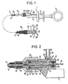
- Figur 1 eine Probenexzessions-Zange mit in Draufsicht dargestellter Handbetätigungseinrichtung und in vergrößertem Schnitt dargestellter Zange und
Figur 2 eine vergrößerte Darstellung des patientennahen Endes der Handbetätigungseinrichtung.
- FIG. 1 shows a sample excitation forceps with a manual actuation device shown in plan view and forceps shown in an enlarged section and
- Figure 2 is an enlarged view of the end of the manual control device near the patient.
Die in den Figuren dargestellte, chirugische Probenexzessions-Zange umfaßt eine Handbetätigungseinrichtung 1, die über ein flexibles, vergleichweise dünnes, aber langes Betätigungskabel 3 mit einer Zange 5 zu einer betriebsmäßig nicht trennbaren Einheit verbunden ist. Die Handbetätigungseinrichtung 1 umfaßt einen Führungsschaft 7, der an seinem patientenfernen Ende einen Daumenring 9 trägt. Am patientennahen Ende des Führungsschafts 7 ist ein Befestigungsrohr 11 angebracht, an dem in nachstehend noch näher erläuterter Weise ein durch eine Federspirale gebildeter Kabelmantel 13 des Betätigungskabels 3 befestigt ist. In dem Kabelmantel 13, der durch eine Kunststoffummantelung 15 nach außen hin abgedichtet ist, ist eine flexible Kabelseele 17 verschiebbar geführt. Die Kabelseele 17 ist über eine das Befestigungsrohr 11 durchsetzende Kupplungsstange 19 mit einem auf dem Führungsschaft 7 verschiebbar geführten Mittelfinger-Zeigefinger-Schiebegriff 21 verbunden. Die Zange 5 ist am patientennahen Ende des Betätigungskabels 3 gehalten und umfaßt ein koaxial am Kabelmantel 13 befestigtes Gabelrohr 23, welches auf seiner kabelmantelfernen Seite 2 einander diametral gegenüberliegende Gabelhälften 25 trägt. An den Gabelhälften 25, von denen in Fig. 1 lediglich eine dargestellt ist, sind an einer diametralen Achse 27 zwei Zangenhälften 29 relativ zueinander und zum Gabelrohr 23 schwenkbar gelagert. Die Zangenhälften 29 sind über Scherenhebel 31 gelenkig mit der Kabelseele 17 gekuppelt. Werden der Daumengriff 9 und der Zeigefinger-Mittelfinger-Schiebegriff 21 aufeinander zubewegt, so wird die Zange 5 geschlossen. Wird der Daumengriff 9 und der Zeigefinger-Mittelfinger-Schiebegriff 21 voneinander wegbewegt, so die Zange 5 geöffnet.The surgical sample excitation forceps shown in the figures comprises a manual actuation device 1 which is connected via a flexible, comparatively thin, but long actuation cable 3 to a forceps 5 to form an operationally inseparable unit. The manual control device 1 comprises a guide shaft 7 which carries a thumb ring 9 at its end remote from the patient. A fastening tube 11 is attached to the end of the guide shaft 7 near the patient, to which a
Die Probenexzessions-Zange kann betriebsmäßig nicht zerlegt werden. Um das Betätigungskabel 3 und insbesondere auch die empfindliche Zange 5 reinigen und desinfizieren zu können, ist an dem Befestigungsrohr 11 ein Spülanschlußstutzen 33, insbesondere ein Luer-Lock-Anschluß befestigt. Der Spülanschlußstutzen 33 ist, wie am besten Fig. 2 zeigt, mit dem Innenraum des Kabelmantels 13 verbunden. Der Kabelmantel 13 ist in einer stirnseitigen Aussparung 35 einer die Kupplungsstange 19 koaxial umschließenden und koaxial in dem Befestigungsrohr 11 sitzenden Hülse 37 gehalten. Auf der patientennahen Seite des Befestigungsrohrs 11 trägt die Hülse 37 einen radial nach außen vorspringenden Ringansatz 39, über den eine auf ein Außengewinde 41 des Befestigungsrohrs 11 geschraubte Überwurfmutter 43 die Hülse 37 an dem Befestigungsrohr 11 hält. Die Ummantelung 15 überdeckt auch den auf der patientennahen Seite der Überwurfmutter 43 vorstehenden Bereich der Hülse 37.The sample excision forceps cannot be disassembled during operation. In order to be able to clean and disinfect the actuating cable 3 and in particular also the sensitive pliers 5, a flushing
Im Bereich des Spülanschlußstutzens 33, der durch eine radiale Öffnung 45 mit dem Innenraum des Befestigungsrohrs 11 verbunden ist, ist die Hülse 37 mit einer über ihren Außenumfang umlaufenden Ringnut 47 versehen. Die Ringnut 47 bildet einen Ringraum, über den sich die Spülflüssigkeit am Umfang der Hülse 37 verteilen kann. Zwischen dem Innenmantel der Hülse 37 und der Kupplungsstange 19 ist ein weiterer Ringraum 49 gebildet, der über mehrere radiale Öffnungen 51 am Boden der Ringnut 47 mit dieser verbunden ist. Der Ringraum 49 erstreckt sich bis in den Innenraum des Kabelmantels 13 hinein.In the area of the flushing connecting
Zur patientenfernen Seite hin ist der Ringraum 49 durch eine die Kupplungsstange 19 dicht umschließende Ringdichtung 53 abgedichtet, die zwischen der patientenfernen axialen Stirnseite der Hülse 37 und einer radial nach innen vorspringenden, axial zur Hülse 37 weisenden Ringschulter 55 des Befestigungsrohrs 11 eingespannt ist. Eine weitere Ringdichtung 57, die in eine den Außenumfang der Hülse 37 umschließende Ringnut 59 eingeschnappt ist, dichtet die patientennahe, axiale Stirnfläche des Befestigungsrohrs 11 gegen die durch den Ringansatz 39 gebildete, zum Befestigungsrohr 11 axial gerichtete Ringschulter 61 ab. Die Spannkräfte werden mittels der Überwurfmutter 43 erzeugt.To the patient-distant side, the
Durch Einspülen einer Spülflüssigkeit in den Spülanschlußstutzen 33 kann das Innere des Kabelmantels 13 einschließlich der ansonsten nur schwer zugänglichen Gelenkteile der Zange 5 gereinigt und desinfiziert werden.By flushing a rinsing liquid into the
Claims (5)
Priority Applications (1)
| Application Number | Priority Date | Filing Date | Title |
|---|---|---|---|
| AT85106030T ATE60704T1 (en) | 1984-05-18 | 1985-05-15 | SURGICAL GRIPPER. |
Applications Claiming Priority (2)
| Application Number | Priority Date | Filing Date | Title |
|---|---|---|---|
| DE8415222U | 1984-05-18 | ||
| DE8415222 | 1984-05-18 |
Publications (3)
| Publication Number | Publication Date |
|---|---|
| EP0165472A2 EP0165472A2 (en) | 1985-12-27 |
| EP0165472A3 EP0165472A3 (en) | 1987-09-09 |
| EP0165472B1 true EP0165472B1 (en) | 1991-02-06 |
Family
ID=6767038
Family Applications (1)
| Application Number | Title | Priority Date | Filing Date |
|---|---|---|---|
| EP85106030A Expired - Lifetime EP0165472B1 (en) | 1984-05-18 | 1985-05-15 | Surgical gripping instrument |
Country Status (4)
| Country | Link |
|---|---|
| US (1) | US4646751A (en) |
| EP (1) | EP0165472B1 (en) |
| AT (1) | ATE60704T1 (en) |
| DE (1) | DE3581665D1 (en) |
Cited By (2)
| Publication number | Priority date | Publication date | Assignee | Title |
|---|---|---|---|---|
| DE19510707A1 (en) * | 1995-03-15 | 1996-09-19 | Uwe Dipl Ing Dey | Maintaining cleanliness inside medical working instrument inserted in live body |
| DE19630324A1 (en) * | 1996-07-26 | 1998-01-29 | Herbert Maslanka | Surgical endoscope flexible operating cable |
Families Citing this family (83)
| Publication number | Priority date | Publication date | Assignee | Title |
|---|---|---|---|---|
| US5133727A (en) * | 1990-05-10 | 1992-07-28 | Symbiosis Corporation | Radial jaw biopsy forceps |
| US6264617B1 (en) | 1977-09-12 | 2001-07-24 | Symbiosis Corporation | Radial jaw biopsy forceps |
| FR2582504A1 (en) * | 1985-06-04 | 1986-12-05 | Schintgen Jean Marie | IMPROVEMENTS ON BIOPSY CLAMPS |
| US4763668A (en) * | 1985-10-28 | 1988-08-16 | Mill Rose Laboratories | Partible forceps instrument for endoscopy |
| US5035248A (en) * | 1987-04-23 | 1991-07-30 | Zinnecker Hal P | Polyolefin sheath and silicone O-ring for medical instrument |
| US5048538A (en) * | 1989-11-27 | 1991-09-17 | Vance Products Incorporated | Biopsy instrument |
| DE3800331A1 (en) * | 1988-01-08 | 1989-07-27 | Fehling Medizintechnik Gmbh | MICROSURGICAL PLIERS, IN PART. FOR BIOPSY |
| US4815476A (en) * | 1988-03-28 | 1989-03-28 | Cordis Corporation | Biopsy forceps with locking handle |
| US4945920A (en) * | 1988-03-28 | 1990-08-07 | Cordis Corporation | Torqueable and formable biopsy forceps |
| US4887612A (en) * | 1988-04-27 | 1989-12-19 | Esco Precision, Inc. | Endoscopic biopsy forceps |
| US5201739A (en) * | 1988-05-17 | 1993-04-13 | Wisap Gesellschaft Fur Wissenschaftlichen Apparatebau Mbh | Medical instrument |
| US4880015A (en) * | 1988-06-03 | 1989-11-14 | Nierman David M | Biopsy forceps |
| US5486185A (en) * | 1989-01-30 | 1996-01-23 | Dexide, Inc. | Surgical apparatus |
| US5172700A (en) * | 1989-01-31 | 1992-12-22 | C. R. Bard, Inc. | Disposable biopsy forceps |
| US5052402A (en) * | 1989-01-31 | 1991-10-01 | C.R. Bard, Inc. | Disposable biopsy forceps |
| US5331971A (en) * | 1990-05-10 | 1994-07-26 | Symbiosis Corporation | Endoscopic surgical instruments |
| US5478347A (en) * | 1990-10-05 | 1995-12-26 | United States Surgical Corporation | Endoscopic surgical instrument having curved blades |
| CA2050868C (en) * | 1990-10-05 | 2002-01-01 | Ernie Aranyi | Endoscopic surgical instrument |
| US5509922A (en) * | 1990-10-05 | 1996-04-23 | United States Surgical Corporation | Endoscopic surgical instrument |
| US5489292A (en) * | 1990-10-05 | 1996-02-06 | United States Surgical Corporation | Endoscopic surgical instrument with grip enhancing means |
| US5626609A (en) * | 1990-10-05 | 1997-05-06 | United States Surgical Corporation | Endoscopic surgical instrument |
| US5486189A (en) * | 1990-10-05 | 1996-01-23 | United States Surgical Corporation | Endoscopic surgical instrument |
| US5209747A (en) * | 1990-12-13 | 1993-05-11 | Knoepfler Dennis J | Adjustable angle medical forceps |
| US5176700A (en) * | 1991-01-22 | 1993-01-05 | Pod, Inc. | Laparoscopic sponger-dissector forceps |
| CA2061885A1 (en) * | 1991-03-14 | 1992-09-15 | David T. Green | Approximating apparatus for surgical jaw structure |
| US5336232A (en) * | 1991-03-14 | 1994-08-09 | United States Surgical Corporation | Approximating apparatus for surgical jaw structure and method of using the same |
| US5217460A (en) * | 1991-03-22 | 1993-06-08 | Knoepfler Dennis J | Multiple purpose forceps |
| US5300087A (en) * | 1991-03-22 | 1994-04-05 | Knoepfler Dennis J | Multiple purpose forceps |
| US5176699A (en) * | 1991-06-05 | 1993-01-05 | Harold Markham | Surgical device with double jaw actuation |
| AU2377492A (en) * | 1991-07-16 | 1993-02-23 | Davinci Medical, Inc. | Surgical instrument actuator |
| EP0526115B1 (en) * | 1991-07-29 | 1997-04-02 | Smith & Nephew Richards Inc | Forceps |
| FR2687053A1 (en) * | 1992-02-10 | 1993-08-13 | Martos Gilbert | Precision automatic disinfecting clamp for medical, veterinary and aesthetic use, and which can be used by any individual |
| US5514157A (en) * | 1992-02-12 | 1996-05-07 | United States Surgical Corporation | Articulating endoscopic surgical apparatus |
| US5209755A (en) * | 1992-06-05 | 1993-05-11 | Stella Abrahan | Dermal exciser |
| JP3518603B2 (en) * | 1992-06-24 | 2004-04-12 | マイクロサージ・インコーポレーテツド | Surgical tool assembly and surgical instrument |
| US5478351A (en) * | 1992-06-24 | 1995-12-26 | Microsurge, Inc. | Endoscopic surgical tool with handle and detachable tool assembly |
| US5368606A (en) * | 1992-07-02 | 1994-11-29 | Marlow Surgical Technologies, Inc. | Endoscopic instrument system |
| US5290308A (en) * | 1992-07-15 | 1994-03-01 | Edward Weck Incorporated | Endoscopic instrument |
| CA2101293C (en) * | 1992-08-05 | 2004-06-29 | David A. Nicholas | Articulating endoscopic surgical apparatus |
| CA2106039A1 (en) * | 1992-09-23 | 1994-03-24 | David A. Nicholas | Surgical biopsy forceps apparatus |
| US5601224A (en) * | 1992-10-09 | 1997-02-11 | Ethicon, Inc. | Surgical instrument |
| US5662662A (en) * | 1992-10-09 | 1997-09-02 | Ethicon Endo-Surgery, Inc. | Surgical instrument and method |
| US5626587A (en) * | 1992-10-09 | 1997-05-06 | Ethicon Endo-Surgery, Inc. | Method for operating a surgical instrument |
| US5683359A (en) * | 1992-11-18 | 1997-11-04 | Symbiosis Corporation | Arthroscopic surgical instruments having suction capability |
| US5327908A (en) * | 1993-01-08 | 1994-07-12 | United States Surgical Corporation | Surgical apparatus for measuring body tissue |
| AU6236794A (en) * | 1993-02-22 | 1994-09-14 | Valleylab, Inc. | A laparoscopic dissection tension retractor device and method |
| CA2159348A1 (en) * | 1993-04-30 | 1994-11-10 | Claude A. Vidal | Surgical instrument having an articulated jaw structure and a detachable knife |
| US6716232B1 (en) * | 1993-04-30 | 2004-04-06 | United States Surgical Corporation | Surgical instrument having an articulated jaw structure and a detachable knife |
| US5373854A (en) * | 1993-07-15 | 1994-12-20 | Kolozsi; William Z. | Biopsy apparatus for use in endoscopy |
| US5417709A (en) * | 1994-04-12 | 1995-05-23 | Symbiosis Corporation | Endoscopic instrument with end effectors forming suction and/or irrigation lumens |
| US5591202A (en) * | 1994-04-28 | 1997-01-07 | Symbiosis Corporation | Endoscopic instruments having low friction sheath |
| US5569298A (en) * | 1994-05-02 | 1996-10-29 | Schnell; William J. | Resposable scissors |
| US6015426A (en) * | 1994-07-13 | 2000-01-18 | Tnco, Inc. | Rotatable linkage for micro-instrument |
| US5549636A (en) * | 1994-10-05 | 1996-08-27 | Li Medical Technologies Inc. | Surgical grasper with articulated fingers |
| US5797959A (en) * | 1995-09-21 | 1998-08-25 | United States Surgical Corporation | Surgical apparatus with articulating jaw structure |
| EP0918485B1 (en) * | 1996-01-11 | 2008-07-30 | Symbiosis Corporation | Flexible microsurgical instruments incorporating a sheath having tactile and visual position indicators |
| US5820009A (en) * | 1996-02-20 | 1998-10-13 | Richard-Allan Medical Industries, Inc. | Articulated surgical instrument with improved jaw closure mechanism |
| US5797537A (en) * | 1996-02-20 | 1998-08-25 | Richard-Allan Medical Industries, Inc. | Articulated surgical instrument with improved firing mechanism |
| US5700275A (en) * | 1996-04-25 | 1997-12-23 | United States Surgical Corporation | Articulating endoscopic surgical instrument |
| US5762613A (en) * | 1996-05-07 | 1998-06-09 | Spectrascience, Inc. | Optical biopsy forceps |
| US6142956A (en) | 1996-11-25 | 2000-11-07 | Symbiosis Corporation | Proximal actuation handle for a biopsy forceps instrument having irrigation and aspiration capabilities |
| US7347828B2 (en) * | 1996-11-25 | 2008-03-25 | Boston Scientific Miami Corporation | Suction adapter for medical instrument |
| US5897507A (en) | 1996-11-25 | 1999-04-27 | Symbiosis Corporation | Biopsy forceps instrument having irrigation and aspiration capabilities |
| US6331165B1 (en) * | 1996-11-25 | 2001-12-18 | Scimed Life Systems, Inc. | Biopsy instrument having irrigation and aspiration capabilities |
| US6139563A (en) * | 1997-09-25 | 2000-10-31 | Allegiance Corporation | Surgical device with malleable shaft |
| US6066102A (en) * | 1998-03-09 | 2000-05-23 | Spectrascience, Inc. | Optical biopsy forceps system and method of diagnosing tissue |
| US6273882B1 (en) | 1998-06-18 | 2001-08-14 | Scimed Life Systems | Snap handle assembly for an endoscopic instrument |
| US6086586A (en) * | 1998-09-14 | 2000-07-11 | Enable Medical Corporation | Bipolar tissue grasping apparatus and tissue welding method |
| DE19945228C1 (en) * | 1999-09-21 | 2001-06-07 | Storz Karl Gmbh & Co Kg | Medical instrument |
| ITCE990004A1 (en) * | 1999-10-25 | 2000-01-25 | Mario Immacolato Paternuosto | VALVE FOR BIOPSY FORCEPS IN DIGESTIVE ENDOSCOPY |
| US7137988B2 (en) * | 2001-03-03 | 2006-11-21 | Frye Darrin L | Needle driver |
| US7494501B2 (en) * | 2003-11-12 | 2009-02-24 | Applied Medical Resources Corporation | Overmolded grasper jaw |
| AU2006206544B2 (en) * | 2005-01-20 | 2010-08-26 | Cook Medical Technologies Llc | Biopsy forceps |
| US20070244513A1 (en) * | 2006-04-14 | 2007-10-18 | Ethicon Endo-Surgery, Inc. | Endoscopic device |
| US8313500B2 (en) * | 2006-04-14 | 2012-11-20 | Ethicon Endo-Surgery, Inc. | Endoscopic device |
| US7857827B2 (en) * | 2006-04-14 | 2010-12-28 | Ethicon Endo-Surgery, Inc. | Endoscopic device |
| US7998167B2 (en) * | 2006-04-14 | 2011-08-16 | Ethicon Endo-Surgery, Inc. | End effector and method of manufacture |
| JP5377991B2 (en) * | 2008-02-26 | 2013-12-25 | テルモ株式会社 | manipulator |
| CN101695457B (en) * | 2009-11-02 | 2012-05-23 | 重庆金山科技(集团)有限公司 | Firmly positioning device of mobile cavity |
| US8623064B2 (en) * | 2010-04-30 | 2014-01-07 | Medtronic Vascular, Inc. | Stent graft delivery system and method of use |
| DE202014006636U1 (en) * | 2014-08-14 | 2014-10-24 | Bacher Medizintechnik GmbH | Tubular shaft instrument with a tubular shaft and a flushing connection |
| CN112122231B (en) * | 2020-09-04 | 2022-08-12 | 北京中科盛康科技有限公司 | Cleaning device for biopsy forceps |
| RU206953U1 (en) * | 2021-02-16 | 2021-10-04 | Михаил Андреевич Кульминский | ENDOSCOPIC TONGS |
Family Cites Families (11)
| Publication number | Priority date | Publication date | Assignee | Title |
|---|---|---|---|---|
| US1294284A (en) * | 1918-11-14 | 1919-02-11 | Charles Frederick Logeman | Tweezers for surgical operations. |
| US1845727A (en) * | 1930-10-04 | 1932-02-16 | George H Slaughter | Trocar |
| US2031682A (en) * | 1932-11-18 | 1936-02-25 | Wappler Frederick Charles | Method and means for electrosurgical severance of adhesions |
| US2113246A (en) * | 1937-05-17 | 1938-04-05 | Wappler Frederick Charles | Endoscopic forceps |
| US3606878A (en) * | 1968-10-04 | 1971-09-21 | Howard B Kellogg Jr | Needle instrument for extracting biopsy sections |
| US3850175A (en) * | 1972-07-03 | 1974-11-26 | J Lglesias | Resectoscope with continuous irrigation |
| JPS5176120A (en) * | 1974-12-27 | 1976-07-01 | Showa Aluminium Co Ltd | |
| US3964468A (en) * | 1975-05-30 | 1976-06-22 | The Board Of Trustees Of Leland Stanford Junior University | Bioptome |
| FR2332743A1 (en) * | 1975-11-28 | 1977-06-24 | Inst Nat Sante Rech Med | Probe for cerebral biopsy - has coaxial internal and external needles with lateral openings in line |
| JPS6034241Y2 (en) * | 1977-04-25 | 1985-10-12 | オリンパス光学工業株式会社 | Endoscope passage sealing device |
| US4167943A (en) * | 1977-06-27 | 1979-09-18 | Surgical Design Corp. | Blade type rotatable surgical cutting instrument with improved cutter blade wear |
-
1985
- 1985-05-15 EP EP85106030A patent/EP0165472B1/en not_active Expired - Lifetime
- 1985-05-15 DE DE8585106030T patent/DE3581665D1/en not_active Expired - Lifetime
- 1985-05-15 AT AT85106030T patent/ATE60704T1/en not_active IP Right Cessation
- 1985-05-17 US US06/735,313 patent/US4646751A/en not_active Expired - Fee Related
Cited By (3)
| Publication number | Priority date | Publication date | Assignee | Title |
|---|---|---|---|---|
| DE19510707A1 (en) * | 1995-03-15 | 1996-09-19 | Uwe Dipl Ing Dey | Maintaining cleanliness inside medical working instrument inserted in live body |
| DE19630324A1 (en) * | 1996-07-26 | 1998-01-29 | Herbert Maslanka | Surgical endoscope flexible operating cable |
| DE19630324B4 (en) * | 1996-07-26 | 2006-05-24 | Herbert Maslanka | Surgical instrument |
Also Published As
| Publication number | Publication date |
|---|---|
| US4646751A (en) | 1987-03-03 |
| EP0165472A3 (en) | 1987-09-09 |
| DE3581665D1 (en) | 1991-03-14 |
| ATE60704T1 (en) | 1991-02-15 |
| EP0165472A2 (en) | 1985-12-27 |
Similar Documents
| Publication | Publication Date | Title |
|---|---|---|
| EP0165472B1 (en) | Surgical gripping instrument | |
| DE3803212C2 (en) | ||
| DE3800331A1 (en) | MICROSURGICAL PLIERS, IN PART. FOR BIOPSY | |
| DE3037110C2 (en) | End plug in a suction channel of an endoscope | |
| EP0710087B1 (en) | Surgical instrument | |
| DE2828638C3 (en) | Endoscope with an instrument channel for a controllable instrument | |
| DE19945228C1 (en) | Medical instrument | |
| DE3722116C2 (en) | ||
| EP0172838A1 (en) | Sample taking device. | |
| EP0412282A1 (en) | Endoscope for nasal surgery | |
| EP0998212A1 (en) | Water, air and suction valves on endoscopes | |
| EP2281516B1 (en) | Surgical instrument | |
| DE3249399C2 (en) | Device for sterile sampling from a fermenter | |
| DE8415222U1 (en) | Surgical grasping instrument | |
| DE19819432C2 (en) | Handpiece for a medical device for suction and rinsing | |
| EP0865299A1 (en) | Apparatus for cleansing and/or disinfecting surgical instruments | |
| DE4220644C1 (en) | Surgical instrument with sliding actuating member - has annular grommets sealed to member and enclosing tube at inner and outer edges at forward and rear ends | |
| DE4412171A1 (en) | Surgical instrument for endoscopy | |
| EP0446804A2 (en) | Arterial puncture set | |
| AT502947B1 (en) | ASEPTIC SAMPLING STATION | |
| DE4236329A1 (en) | Endoscopic laser instrument e.g. for laparoscopy - has operating member which is displaceable along axis of instrument, and valve junctions which are rotatable around handpiece, with light guide located in fluid flow channel | |
| DE4333746A1 (en) | Surgical tool operating instrument - has a tube which can be rotated in relation to the pull system and locked in place. | |
| DE4402677B4 (en) | Method and device for rinsing a pipe wrench | |
| DE4415360C2 (en) | Surgical instrument | |
| DE3431179A1 (en) | SYSTEM OF VALVES AND PIPES FOR VETERINE MEDICAL AND MEDICAL INSTRUMENTS, AND METHOD FOR CONTROLLING THE SUCTION EFFECT IN SUCH A SYSTEM |
Legal Events
| Date | Code | Title | Description |
|---|---|---|---|
| PUAI | Public reference made under article 153(3) epc to a published international application that has entered the european phase |
Free format text: ORIGINAL CODE: 0009012 |
|
| AK | Designated contracting states |
Designated state(s): AT DE FR GB NL |
|
| PUAL | Search report despatched |
Free format text: ORIGINAL CODE: 0009013 |
|
| AK | Designated contracting states |
Kind code of ref document: A3 Designated state(s): AT DE FR GB NL |
|
| 17P | Request for examination filed |
Effective date: 19880217 |
|
| 17Q | First examination report despatched |
Effective date: 19900406 |
|
| GRAA | (expected) grant |
Free format text: ORIGINAL CODE: 0009210 |
|
| AK | Designated contracting states |
Kind code of ref document: B1 Designated state(s): AT DE FR GB NL |
|
| PG25 | Lapsed in a contracting state [announced via postgrant information from national office to epo] |
Ref country code: NL Effective date: 19910206 Ref country code: GB Effective date: 19910206 Ref country code: FR Effective date: 19910206 |
|
| REF | Corresponds to: |
Ref document number: 60704 Country of ref document: AT Date of ref document: 19910215 Kind code of ref document: T |
|
| REF | Corresponds to: |
Ref document number: 3581665 Country of ref document: DE Date of ref document: 19910314 |
|
| PG25 | Lapsed in a contracting state [announced via postgrant information from national office to epo] |
Ref country code: AT Effective date: 19910515 |
|
| EN | Fr: translation not filed | ||
| NLV1 | Nl: lapsed or annulled due to failure to fulfill the requirements of art. 29p and 29m of the patents act | ||
| GBV | Gb: ep patent (uk) treated as always having been void in accordance with gb section 77(7)/1977 [no translation filed] | ||
| PLBI | Opposition filed |
Free format text: ORIGINAL CODE: 0009260 |
|
| 26 | Opposition filed |
Opponent name: NIELS RUDI PEDERSEN Effective date: 19911106 |
|
| PGFP | Annual fee paid to national office [announced via postgrant information from national office to epo] |
Ref country code: DE Payment date: 19930615 Year of fee payment: 9 |
|
| RDAG | Patent revoked |
Free format text: ORIGINAL CODE: 0009271 |
|
| STAA | Information on the status of an ep patent application or granted ep patent |
Free format text: STATUS: PATENT REVOKED |
|
| 27W | Patent revoked |
Effective date: 19930718 |