EP0166209A2 - Device for checking protective measures in electrical equipment - Google Patents
Device for checking protective measures in electrical equipment Download PDFInfo
- Publication number
- EP0166209A2 EP0166209A2 EP85106334A EP85106334A EP0166209A2 EP 0166209 A2 EP0166209 A2 EP 0166209A2 EP 85106334 A EP85106334 A EP 85106334A EP 85106334 A EP85106334 A EP 85106334A EP 0166209 A2 EP0166209 A2 EP 0166209A2
- Authority
- EP
- European Patent Office
- Prior art keywords
- measuring
- plug
- measuring device
- contact
- protective
- Prior art date
- Legal status (The legal status is an assumption and is not a legal conclusion. Google has not performed a legal analysis and makes no representation as to the accuracy of the status listed.)
- Granted
Links
Images


Classifications
-
- G—PHYSICS
- G01—MEASURING; TESTING
- G01R—MEASURING ELECTRIC VARIABLES; MEASURING MAGNETIC VARIABLES
- G01R19/00—Arrangements for measuring currents or voltages or for indicating presence or sign thereof
- G01R19/145—Indicating the presence of current or voltage
-
- G—PHYSICS
- G01—MEASURING; TESTING
- G01R—MEASURING ELECTRIC VARIABLES; MEASURING MAGNETIC VARIABLES
- G01R15/00—Details of measuring arrangements of the types provided for in groups G01R17/00 - G01R29/00, G01R33/00 - G01R33/26 or G01R35/00
- G01R15/08—Circuits for altering the measuring range
- G01R15/09—Autoranging circuits
Definitions
- the invention relates to a measuring device mentioned in the preamble of claim 1.
- the measuring lines of the device are connected to a three-pin measuring plug, which can be plugged into the earthed sockets.
- the measurement itself is not three-pole, but only two-pole, ie of the three poles of the measuring plug consisting of protective contact and two plug pins, only two are required as measuring contacts which absorb potential differences between certain conductors of the network.
- measurements must be made between the phase conductor L and the protective conductor PE or between the phase conductor L and the neutral conductor N.
- the checking of the protective measures is not only limited to sockets, but must of course also be able to be carried out directly on the conductors in systems.
- the three-pin measuring plug is unsuitable for contacting, so that it is replaced in known measuring devices by three measuring lines with banana plugs or connected to them by an adapter. Again, it is annoying that the three banana plugs must be carefully monitored for polarity.
- a measured variable for example the network loop resistance and the resulting short-circuit current
- several individual measurements must be carried out in succession, in which the measuring device must be operated.
- the measuring device For operation, as in the "de / der elektromeister + deutsches elektrohandtechnik" booklet 3/87, pages 148 to 152 Insulation measuring device described, several switches or buttons required.
- the object of the invention is to design a measuring device of the type mentioned in the preamble of claim 1 so that when connecting the measuring lines of the measuring device to the electrical system to be examined there is no need to pay attention to the polarity (phase) and to carry out the measurement quickly and can be done easily without having to operate the control elements provided on the measuring device during the measurement.
- the automatic measuring system ensures that the three correct poles of the measuring plug are always selected as measuring contacts, there is not only the advantage that when plugging the measuring plug into a socket, the phase position no longer has to be taken into account, but above all also that a three-pole connection can be made from the three-pole at will.
- the measuring plug is not suitable for contacting, it is therefore not necessary to connect three measuring lines to the measuring plug, but two measuring lines with connected banana plugs or measuring tips are sufficient.
- Another advantage of the measuring device according to the invention is that the hand no longer has to be removed from the measuring plug in order to carry out a measurement to the end, but that the movement of a finger is sufficient to actuate the hand switch.
- the automatic measuring system in conjunction with the measured variable switch ensures that the pole pin becomes the measuring contact that comes into contact with the phase, while the pole pin on the neutral conductor or the protective contact changes, if necessary serve as measuring contact.
- a contact adapter which can be placed on the measuring plug is designed as a plug-in pot to which two measuring tips are attached. It is important that one of the two measuring tips is firmly connected to the plug pot, so that the measuring plug can be held in one hand with the attached contact adapter.
- a second measuring tip of the contact adapter is connected to the socket via a measuring cable and can be held in the other hand. A safe measurement on free lines can thus be carried out with both measuring tips, the measuring device being operated via the hand switch.
- a further embodiment of the subject matter of the invention provides that the measuring plug can be used not only to measure sockets with external protective contacts, but also those which are provided with a protective contact pin. This also results in simple contacting of the measuring tip fixedly mounted on the plug pot, which is provided with a protective contact pin which engages in a protective contact socket of the measuring plug.
- phase adjustment that can be achieved by automatic switching is not advantageous in all cases.
- the position of the phase relative to the protective contact pin is mandatory.
- An automatic phase adjustment is undesirable here, since it would prevent a control of the phase position and no measurement between neutral conductor N and protective conductor PE would be possible.
- a voltage measuring range is therefore provided, in which the automatic phase adjustment is switched off and a fixed pole assignment, identified by the measuring plug, applies. With the contact adapter attached, you can measure potential differences between all three conductors in the network in this position of the measuring range switch. The position of the phase can also be determined or checked by measuring the potential differences lying at the leirters.
- a further improvement in the handling of the measuring device is achieved in that a contact is also provided on the measuring plug.
- the contact is automatically touched as soon as you take the measuring plug in your hand. This is very important because a dangerous potential on the protective conductor, but also the position of the phase conductor, can be determined before the actual measurement begins.
- a signal circuit is used, which is connected to the protective contact of the measuring plug with a high resistance via the contact. If there is an impermissible potential difference, a body current flows to earth when touched, which activates the signal circuit. The body current must of course be kept as low as possible and should not reach a questionable value even in the event of a fault chen.
- a protective capacitor which couples the signal circuit to the touch contact, an amplifier ensuring that currents in the microampere range are sufficient to activate the signal circuit.
- the protective capacitor is constructed in such a way that it also meets protection class 2 (test voltage 4 kV) observed by the measuring device.
- the supply of the signal circuit from a battery makes it independent of the mains, so that a dangerous voltage on the protective conductor can also be signaled when there is no voltage on the phase.
- the measuring sequence is initiated by the manual switch which acts on the automatic measuring system, preferably controlled by a microprocessor.
- optical and / or acoustic signaling means are provided on the measuring device, which signal impermissible deviations from certain nominal conditions under which the measurement is to be carried out, in particular impermissible mains voltages.
- the hand switch is expediently designed as a button and the activation of the measuring device initiated by pressing the button is limited to a time limited by a time switch, preferably 15 seconds.
- An embodiment of the hand switch as a slide switch which, in addition to its rest position and a second position for switching on the measuring device, has a third switch position, allows further evaluations or tests to be carried out in this position, which can change depending on the position of the measured variable switch.
- the measuring device is advantageously constructed in such a way that the automatic switch-off does not take effect after approx. 15 s when the hand switch is brought into its third switching position again. This increases the switch-on time by approx. 15 s each.
- the measuring device displays a calculated value which is mathematically derived from the measured value determined with the second switch position by a calculated circuit of the measuring device.
- This calculation value would be e.g. the short-circuit current when the measured variable switch assumes a switch position provided for measuring the loop resistance or the internal resistance.
- a measurement of the earth resistance is possible using the voltage reduction method, but it can be carried out even better by using an earth probe.
- An advantageous development of the measuring device according to the invention therefore provides a socket for connecting an earth probe.
- the socket contains a changeover contact, which places a measuring contact from the measuring plug to the earth probe, so that the pole of the measuring plug that has become free for voltage measurement only serves to conduct the test current.
- the measuring device consists of a housing 25, in which the most important functional units are housed, a measuring plug 2 and a contact adapter 7 that can be plugged onto it.
- a measuring variable switch 1 a socket 19 for connecting an earth probe, LEDs 20 are attached to the housing 25 to 23 for signaling certain error states and a display 30 for displaying certain measured or calculated values.
- the measuring plug 2 is connected via measuring lines 32 to the functional units accommodated in the housing 25. It is designed at its contacted end in accordance with a standardized protective contact plug and has three poles 3 to 5. Two of the poles are as pole pins 3, 4 and a pole as a protective contact 5.
- the protective contact 5, which is external according to the German standard, is connected to a protective contact socket 12, as is prescribed for protective contact plugs in other countries.
- a handle 26 extending the measuring plug 2 carries a slide button 6, which has three switch positions 16 to 18. The middle position of the button 6 is its rest position 16, in which it returns after actuation. If the button 6 is brought into its second position 17 lying at the front, the measuring device is switched on and its automatic measuring system comes into action.
- the automatically determined measured variable which is digitally shown on the display 30, depends on the switching position of the measured variable switch and the preselected measured variable or measurement type. If the boundary conditions to be observed during the measurement are not met, the LEDs 20 to 23 signal the respective error or defect.
- the switch-on time of the device is limited to 15 seconds by an automatic switch-off. However, if the switch 6 is brought into its third position 18 before the device has switched itself off automatically, the operating time is extended by a further 15 seconds.
- the measuring device remains switched on as long as the button is held in its third position 18. Furthermore, the measuring device is designed in such a way that in the third position 18 of the push button 6 it performs additional measuring or computing functions which are generally related to the measurement previously carried out in the second position 17 of the push button 6.
- a contact adapter 7 which can be placed on the measuring plug.
- the contact adapter 7 has a plug 8 for receiving the measuring plug 2, to which a first measuring tip is attached and a second measuring tip 10 connected to the plug 8 via a measuring cable 11.
- the contacts in the plug 8 are placed in such a way that a contact pin 13, which meets the protective contact socket 12 when plugged together, the protective contact PE is connected to the first measuring tip 9.
- Another contact piece connects one of the two connector pins 3, 4 via the measuring cable 11 to the. second measuring tip 10.
- a contact 14 is attached, which puts earth potential over the hand and the body of the contacting the measuring device.
- the contact 14 is the one pole of a protective capacitor which is installed together with an amplifier in the handle 26 and detects the smallest currents which flow from the protective conductor PE via the contact 14 to earth and reports them to one of the light-emitting diodes 20 to 23 for signaling.
- the circuit is designed in such a way that dangerous contact voltages on the protective conductor PE or the position of the phase can be determined before the automatic measuring system is switched on and thus before the actual measurement.
- FIG. 2 shows a block diagram of the measuring device, with the aid of which the interaction of the individual assemblies can be roughly explained.
- the measuring plug 2 is when plugged into a protective contact socket with the Phase conductor L, the neutral conductor N and the protective conductor PE connected.
- a finger contact FK serves as a touch contact to create an external earth potential.
- the selection of the measured variable, which is initially specified on the measured variable switch 1, is carried out by the automatic measuring system 33.
- a microprocessor 38 takes over all control and computing functions.
- An automatic phase matching device 37 ensures the correct polarity or position of the phase at the input of the automatic measuring device 33.
- a constant current source 40 which loads the network with a constant current.
- the constant current can be set to different values with the help of the variable switch.
- the differential voltage that arises during the voltage drop is determined via an integrator 39.
- the respective measurement or calculation variable is output via a display unit and digitally shown on a display 30. Fault conditions are signaled by LEDs. Reading the measured variable on the display 30 can sometimes be avoided by an audible signal generator 34 giving a clearly audible signal when the measured variable is within the prescribed range.
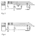
- FIG. 3 again illustrate the possibilities that arise when connecting the measuring device to the network.
- an FI switch is checked for functionality, while according to FIG. 4 an earth resistance is measured.
- Both a measurement with the measuring plug which can be plugged directly into a socket and with the contact adapter placed on the measuring plug are possible.
- the contact adapter advantageously allows two-pole measurement. Both measurements can be carried out with or without an earth probe. If an earth probe is used, as shown in FIG. 4, it is not the voltage drop but the principle of current / voltage measurement that is used.
Abstract
Description
Die Erfindung betrifft ein Meßgerät der im Oberbegriff des Anspruchs 1 genannten Art.The invention relates to a measuring device mentioned in the preamble of claim 1.
Zur Überprüfung der Schutzmaßnahmen in elektrischen Anlagen ist die Erfassung einer Vielzahl von Meßgrößen erforderlich. Bei der Erstellung geeigneter Meßgeräte für die verschiedenen Prüfungen stehen sich zwei unterschiedliche Konzepte gegenüber. So ist es möglich,mehrere auf besondere Prüfungen spezialisierte Einzelgeräte zu entwickeln oder aber das Meßgerät so zu gestalten, daß möglichst viele Prüfungen mit dem selben Gerät durchgeführt werden können. Es muß darauf geachtet werden, daß der durch ein Konzept der zweiten Art erreichte Vorteil, daß nur ein Gerät an den Einsatzort mitgenommen werden muß, nicht durch eine komplizierte Bedienung zum Teil wieder aufgehoben wird.To check the protective measures in electrical systems, a large number of measured variables must be recorded. When creating suitable measuring devices for the different tests, there are two different concepts. This makes it possible to develop several individual devices specializing in special tests or to design the measuring device so that as many tests as possible can be carried out with the same device. Care must be taken to ensure that the advantage achieved by a concept of the second type, that only one device has to be taken to the place of use, is not partially offset by complicated operation.
Die meisten Prüfungen werden unmittelbar an den Schutzkontaktsteckdosen des Niederspannungsnetzes durchgeführt. Hierzu sind die Meßleitungen des Gerätes mit einem dreipoligen Meßstecker verbunden, der in die Schutzkontaktsteckdosen eingesteckt werden kann. Die Messung selbst erfolgt jedoch nicht dreipolig sondern nur zweipolig, d.h. von den drei aus Schutzkontakt und zwei Steckerstiften bestehenden Polen des Meßsteckers werden nur zwei als Meßkontakte benötigt, die Potentialdifferenzen zwischen bestimmten Leitern des Netzes aufnehmen. Je nach Art der zu ermittelnden Meßgröße muß zwischen dem Phasenleiter L und dem Schutzleiter PE oder zwischen dem Phasenleiter L und dem Null-Leiter N gemessen werden. Da vor der Messung nicht bekannt ist, an welchen der beiden Buchsen einer Steckdose der Phasenleiter liegt, muß dessen Lage bei herkömmlichen Meßgeräten zunächst durch eine Phasenprüfung festgestellt werden. Danach ist der Meßstecker entsprechend der an seinen Polen vorgesehenen Kennzeichnung richtig einzustecken. Obwohl die Messung im Prinzip zweipolig durchgeführt wird, müssen bei den meisten bekannten Geräten dennoch alle drei Pole angeschlossen werden, da die Stromversorgung dieser Geräte über das Netz erfolgt.Most tests are carried out directly on the earthed sockets of the low-voltage network. For this purpose, the measuring lines of the device are connected to a three-pin measuring plug, which can be plugged into the earthed sockets. However, the measurement itself is not three-pole, but only two-pole, ie of the three poles of the measuring plug consisting of protective contact and two plug pins, only two are required as measuring contacts which absorb potential differences between certain conductors of the network. Depending on the type of measured variable to be determined, measurements must be made between the phase conductor L and the protective conductor PE or between the phase conductor L and the neutral conductor N. Since it is not known before the measurement at which of the two sockets of a socket the phase conductor is located, its position in conventional measuring devices must first be determined by a phase test. Then the measuring plug must be inserted correctly in accordance with the marking provided on its poles. Although the measurement is carried out in principle with two poles, most of the known devices still have to be connected to all three poles, since these devices are supplied with power via the network.
Die Überprüfung der Schutzmaßnahmen beschränkt sich nicht nur auf Steckdosen, sondern muß selbstverständlich auch in Anlagen unmittelbar an den Leitern durchführbar sein. Dabei ist der dreipolige Meßstecker für die Kontaktierung ungeeignet, so daß er bei bekannten-Meßgeräten durch drei Meßleitungen mit Bananensteckern ersetzt oder über einen Adapter mit diesen verbunden wird. Hierbei ist wiederum störend, daß bei den drei Bananenstekkern genau auf die Polarität geachtet werden muß.The checking of the protective measures is not only limited to sockets, but must of course also be able to be carried out directly on the conductors in systems. The three-pin measuring plug is unsuitable for contacting, so that it is replaced in known measuring devices by three measuring lines with banana plugs or connected to them by an adapter. Again, it is annoying that the three banana plugs must be carefully monitored for polarity.
Zur Ermittlung einer Meßgröße, z.B. des Netz-Schleifenwiderstandes sowie des daraus resultierenden Kurzschlußstroms, sind nacheinander mehrere Einzelmessungen durchzuführen, bei denen das Meßgerät bedient werden muß. Zur Bedienung sind, wie bei dem in "de/der elektromeister + deutsches elektrohandwerk" Heft 3/87, Seite 148 bis 152 beschriebenen Isolationsmeßgerät, mehrere Schalter oder Taster erforderlich. Für eine Einzelperson ist es aber nun nicht oder doch nur schwer möglich einerseits die Bananenstecker bzw. Meßspitzen an die Netzleitungen zu halten und andererseits das Meßgerät zu bedienen.To determine a measured variable, for example the network loop resistance and the resulting short-circuit current, several individual measurements must be carried out in succession, in which the measuring device must be operated. For operation, as in the "de / der elektromeister + deutsches elektrohandwerk"
Aufgabe der Erfindung ist es, ein Meßgerät der im Oberbegriff des Anspruchs 1 genannten Art so zu gestalten, daß beim Verbinden der Meßleitungen des Meßgerätes mit der zu untersuchenden elektrischen Anlage nicht auf die Polarität (Phase) geachtet werden muß und die Durchführung der Messung schnell und einfach erfolgen kann, ohne daß während der Messung auf dem Meßgerät vorgesehene Bedienelemente betätigt werden müssen.The object of the invention is to design a measuring device of the type mentioned in the preamble of claim 1 so that when connecting the measuring lines of the measuring device to the electrical system to be examined there is no need to pay attention to the polarity (phase) and to carry out the measurement quickly and can be done easily without having to operate the control elements provided on the measuring device during the measurement.
Diese Aufgabe wird durch die im Anspruch 1 gekennzeichneten Merkmale gelöst. Weitere Fortbildungen und zweckmäßige Ausgestaltungen der Erfindung sind in den Unteransprüchen genannt.This object is achieved by the features characterized in claim 1. Further developments and expedient refinements of the invention are mentioned in the subclaims.
Da die Meßautomatik dafür sorgt, daß von den drei Polen des Meßsteckers immer die beiden richtigen als Meßkontakte ausgewählt werden, ergibt sich nicht nur der Vorteil, das beim Einstecken des Meßsteckers in eine Steckdose nicht mehr auf die Phasenlage geachtet werden muß, sondern vor allem auch, daß aus dem Dreipol- nach Belieben ein Zweipolanschluß gemacht werden kann. Für Messungen, bei denen sich der Meßstecker nicht zur Kontaktierung eignet, ist es also nicht erforderlich drei Meßleitungen mit dem Meßstecker zu verbinden, sondern es genügen zwei Meßleitungen mit angeschlossenen Bananenstekkern oder Meßspitzen. Ein weiterer Vorteil des erfindungsgemäßen Meßgerätes ist, daß die Hand nicht mehr vom Meßstecker genommen werden muß, um eine Messung bis zum Ende durchzuführen, sondern daß hierzu die Bewegung eines Fingers zur Betätigung des Handschalters genügt.Since the automatic measuring system ensures that the three correct poles of the measuring plug are always selected as measuring contacts, there is not only the advantage that when plugging the measuring plug into a socket, the phase position no longer has to be taken into account, but above all also that a three-pole connection can be made from the three-pole at will. For measurements in which the measuring plug is not suitable for contacting, it is therefore not necessary to connect three measuring lines to the measuring plug, but two measuring lines with connected banana plugs or measuring tips are sufficient. Another advantage of the measuring device according to the invention is that the hand no longer has to be removed from the measuring plug in order to carry out a measurement to the end, but that the movement of a finger is sufficient to actuate the hand switch.
Um verschiedene Meßgrößen ermitteln zu können, sorgt die Meßautomatik in Verbindung mit dem Meßgrößenumschaler durch geeignete Umschaltung dafür, daß jeweils der Polstift zum Meßkontakt wird, der an Phase zu liegen kommt, während der am Null-Leiter liegende Polstift oder der Schutzkontakt, ggf. wechselnd als Meßkontakt dienen.In order to be able to determine various measured variables, the automatic measuring system in conjunction with the measured variable switch ensures that the pole pin becomes the measuring contact that comes into contact with the phase, while the pole pin on the neutral conductor or the protective contact changes, if necessary serve as measuring contact.
In weiterer Ausgestaltung der Erfindung ist ein auf den Meßstecker aufsetzbarer Kontaktadapter als Stecktopf gestaltet, an dem zwei Meßspitzen befestigt sind. Wichtig ist, daß eine der beiden Meßspitzen mit dem Stecktopf fest verbunden ist, so daß der Meßstecker mit dem aufgesetzten Kontaktadapter in einer Hand gehalten werden kann. Eine zweite Meßspitze des Kontaktadapters ist über ein Meßkabel mit dem Stecktopf verbunden und kann in der anderen Hand gehalten werden. Mit beiden Meßspitzen kann so eine gefahrlose Messung an freien Leitungen erfolgen, wobei die Bedienung des Meßgerätes über den Handschalter erfolgt.In a further embodiment of the invention, a contact adapter which can be placed on the measuring plug is designed as a plug-in pot to which two measuring tips are attached. It is important that one of the two measuring tips is firmly connected to the plug pot, so that the measuring plug can be held in one hand with the attached contact adapter. A second measuring tip of the contact adapter is connected to the socket via a measuring cable and can be held in the other hand. A safe measurement on free lines can thus be carried out with both measuring tips, the measuring device being operated via the hand switch.
Eine weitere Ausgestaltung des Erfindungsgegenstandes sieht vor, daß man mit dem Meßstecker nicht nur an Steckdosen mit außenliegenden Schutzkontakten messen kann, sondern auch an solchen, die mit einem Schutzkontaktstift versehen sind. Hierdurch ergibt sich auch eine einfache Kontaktierung der auf dem Stecktopf fest montierten Meßspitze, die mit einem Schutzkontaktstift versehen ist, der in eine Schutzkontaktbuchse des Meßstekkers eingreift.A further embodiment of the subject matter of the invention provides that the measuring plug can be used not only to measure sockets with external protective contacts, but also those which are provided with a protective contact pin. This also results in simple contacting of the measuring tip fixedly mounted on the plug pot, which is provided with a protective contact pin which engages in a protective contact socket of the measuring plug.
Die durch automatische Umschaltung erzielbare Phasenanpassung ist nicht in allen Fällen von Vorteil. So gibt es Länder in denen Steckdosen mit einem Schutzkontaktstift vorgeschrieben sind, der ein Umpolen des Steckers verhindert. Die Lage der Phase zum Schutzkontaktstift ist vorgeschrieben. Eine automatische Phasenanpassung ist hier unerwünscht, da sie eine Kontrolle der Phasenlage verhindern würde und auch keine Messung zwischen Null-Leiter N und Schutzleiter PE möglich wäre. Es ist deshalb ein Spannungsmeßbereich vorgesehen, bei dem die automatische Phasenanpassung abgeschaltet ist und eine feste und dem Meßstecker gekennzeichnete Polzuordnung gilt. Bei aufgesetztem Kontaktadapter kann man in dieser Stellung des Meßbereichsschalters zwischen allen drei Leitern des Netzes Potentialdifferenzen messen. Durch die Messung der an den Leirtern liegenden Potentialdifferenzen läßt sich auch die Lage der Phase ermitteln oder kontrollieren.The phase adjustment that can be achieved by automatic switching is not advantageous in all cases. There are countries in which sockets with a protective contact pin are prescribed that prevent the plug from being reversed. The position of the phase relative to the protective contact pin is mandatory. An automatic phase adjustment is undesirable here, since it would prevent a control of the phase position and no measurement between neutral conductor N and protective conductor PE would be possible. A voltage measuring range is therefore provided, in which the automatic phase adjustment is switched off and a fixed pole assignment, identified by the measuring plug, applies. With the contact adapter attached, you can measure potential differences between all three conductors in the network in this position of the measuring range switch. The position of the phase can also be determined or checked by measuring the potential differences lying at the leirters.
Eine weitere Verbesserung der Handhabbarkeit des Meßgerätes wird dadurch erreicht, daß am Meßstecker auch noch ein Berührungskontakt vorgesehen ist. Der Berührungskontakt wird automatisch berührt, sobald man den Meßstecker in die Hand nimmt. Das ist sehr wichtig, da ein gefährliches am Schutzleiter liegendes Potential, aber auch die Lage des Phasenleiters, schon vor Beginn der eigentlichen Messung festgestellt werden kann. Hierzu dient eine Signalschaltung, die über den Berührungskontakt hochohmig mit dem Schutzkontakt des Meßsteckers verbunden ist. Bei einer unzulässigen Potentialdifferenz fließt bei Berührung ein Körperstrom gegen Erde, der die Signalschaltung aktiviert. Der Körperstrom muß selbstverständlich so niedrig wie möglich gehalten werden und darf auch im Fehlerfall keinen bedenklichen Wert errei chen. Diese Voraussetzungen werden durch einen Schutzkondensator, der die Signalschaltung mit dem Berührungskontakt koppelt, gewährleistet, wobei ein Verstärker dafür sorgt, daß Ströme im Mikroamperebereich ausreichen, um die Signalschaltung zu aktivieren. Der Schutzkondensator ist so aufgebaut, daß er die vom Meßgerät eingehaltene Schutzklasse 2 (Prüfspg.4 kV) ebenfalls erfüllt.A further improvement in the handling of the measuring device is achieved in that a contact is also provided on the measuring plug. The contact is automatically touched as soon as you take the measuring plug in your hand. This is very important because a dangerous potential on the protective conductor, but also the position of the phase conductor, can be determined before the actual measurement begins. For this purpose, a signal circuit is used, which is connected to the protective contact of the measuring plug with a high resistance via the contact. If there is an impermissible potential difference, a body current flows to earth when touched, which activates the signal circuit. The body current must of course be kept as low as possible and should not reach a questionable value even in the event of a fault chen. These prerequisites are ensured by a protective capacitor which couples the signal circuit to the touch contact, an amplifier ensuring that currents in the microampere range are sufficient to activate the signal circuit. The protective capacitor is constructed in such a way that it also meets protection class 2 (
Die Versorgung der Signalschaltung aus einer Batterie macht diese netzunabhängig, so daß eine am Schutzleiter liegende gefährliche Spannung auch dann signalisiert werden kann, wenn an Phase keine Spannung liegt. Eine vom Netz gespeiste Signalschaltung, wie sie sonst üblich ist, wäre hierzu nicht in der Lage.The supply of the signal circuit from a battery makes it independent of the mains, so that a dangerous voltage on the protective conductor can also be signaled when there is no voltage on the phase. A signal circuit powered by the network, as is otherwise customary, would not be able to do this.
Bei einer zweckmäßigen Ausbildung des Meßgerätes wird der Meßablauf durch den Handschalter initiiert der, auf die, vorzugsweise durch einen Mikroprozessor gesteuerte, Meßautomatik wirkt. Weiterhin sind optische und/oder akustische Signalmittel am Meßgerät vorgesehen, die unzulässige Abweichungen von bestimmten Nennbedingungen, unter denen die Messung durchzuführen ist, insbesondere unzulässige Netzspannungen, signalisieren.If the measuring device is designed appropriately, the measuring sequence is initiated by the manual switch which acts on the automatic measuring system, preferably controlled by a microprocessor. Furthermore, optical and / or acoustic signaling means are provided on the measuring device, which signal impermissible deviations from certain nominal conditions under which the measurement is to be carried out, in particular impermissible mains voltages.
Zweckmäßigerweise wird der Handschalter als Taster ausgebildet und die durch Betätigen der Taste initiierte Einschaltung des Meßgerätes auf eine durch eine Zeitschaltung begrenzte Zeit, vorzugsweise 15 Sekunden, beschränkt.The hand switch is expediently designed as a button and the activation of the measuring device initiated by pressing the button is limited to a time limited by a time switch, preferably 15 seconds.
Eine Ausbildung des Handschalters als Schiebetaster, der außer seiner Ruhestellung und einer zweiten Stellung für das Einschalten des Meßgerätes eine dritte Schaltstellung besitzt, erlaubt es in dieser Stellung weitere Auswertungen oder Prüfungen vorzunehmen, die je nach Stellung des Meßgrößenumschalters wechseln können. Außerdem ist das Meßgerät vorteilhaft so aufgebaut, daß die automatische Abschaltung nach ca. 15 s nicht wirksam wird, wenn der Handschalter erneut in seine dritte Schaltstellung gebracht wird. Hierdurch verlängert sich die Einschaltzeit um jeweils ca. 15 s.An embodiment of the hand switch as a slide switch, which, in addition to its rest position and a second position for switching on the measuring device, has a third switch position, allows further evaluations or tests to be carried out in this position, which can change depending on the position of the measured variable switch. In addition, the measuring device is advantageously constructed in such a way that the automatic switch-off does not take effect after approx. 15 s when the hand switch is brought into its third switching position again. This increases the switch-on time by approx. 15 s each.
Vorteilhaft ist es, wenn das Meßgerät in der dritten Schaltstellung des Handschalters einen Rechenwert anzeigt, der von dem mit der zweiten Schaltstellung ermittelten Meßwert durch eine Rechenschaltung des Meßgerätes mathematisch abgeleitet wird. Dieser Rechenwert wäre z.B. der Kurzschlußstrom, wenn der Meßgrößenumschalter eine zur Messung des Schleifenwiderstandes oder des Innenwiderstandes vorgesehene Schaltstellung einnimmt.It is advantageous if, in the third switch position of the hand switch, the measuring device displays a calculated value which is mathematically derived from the measured value determined with the second switch position by a calculated circuit of the measuring device. This calculation value would be e.g. the short-circuit current when the measured variable switch assumes a switch position provided for measuring the loop resistance or the internal resistance.
Es ist weiterhin möglich die dritte Schaltstellung des Handschalters dahingehend zu nutzen, daß über die beiden Meßkontakte ein Prüfstrom fließt, der etwa dem Nennfehlerstrom eines zu prüfenden Fehlerstromschutzschalters entspricht, wenn der Meßgrößenumschalter eine zur Messung der Berührungsspannung vorgesehene Schaltstellung einnimmt.It is also possible to use the third switch position of the hand switch in such a way that a test current flows via the two measuring contacts which corresponds approximately to the nominal residual current of a residual current circuit breaker to be tested if the measured variable switch assumes a switch position provided for measuring the contact voltage.
Eine Messung des Erdungswiderstandes ist durch das Spannungsabsenkungsverfahren möglich, aber besser noch durch Verwendung einer Erdsonde durchführbar. Eine vorteilhafte Weiterbildung des erfindungsgemäßen Meßgerätes sieht deshalb eine Buchse zum Anschließen einer Erdsonde vor. Die Buchse enthält einen Umschaltkontakt, der einen Meßkontakt vom Meßstecker an die Erdsonde legt, so daß der für die Spannungsmessung frei gewordene Pol des Meßstekkers nur zum Leiten des Prüfstroms dient.
Ein Ausführungsbeispiel des erfindungsgemäßen Meßgerätes wird im folgenden näher beschrieben und in den Zeichnungen dargestellt.A measurement of the earth resistance is possible using the voltage reduction method, but it can be carried out even better by using an earth probe. An advantageous development of the measuring device according to the invention therefore provides a socket for connecting an earth probe. The socket contains a changeover contact, which places a measuring contact from the measuring plug to the earth probe, so that the pole of the measuring plug that has become free for voltage measurement only serves to conduct the test current.
An embodiment of the measuring device according to the invention is described in more detail below and shown in the drawings.
Es zeigen:
- Figur 1: Den Aufbau des erfindungsgemäßen Meßgerätes.
- Figur 2: Ein Blockschaltbild des Meßgerätes.
- Figur 3: Die Anwendung des Meßgerätes bei der FI-Schalterprüfung.
- Figur 4: Die Anwendung des Meßgerätes bei der Messung des Erdungswiderstandes.
- Figure 1: The structure of the measuring device according to the invention.
- Figure 2: A block diagram of the measuring device.
- Figure 3: The use of the measuring device in the FI switch test.
- Figure 4: The application of the measuring device in the measurement of the earth resistance.
Wie Figur 1 zeigt, besteht das Meßgerät aus einem Gehäuse 25, in dem die wichtigsten Funktionseinheiten untergebracht sind, einem Meßstecker 2 und einem auf diesen aufsteckbaren Kontaktadapter 7. Am Gehäuse 25 sind ein Meßgrößenumschalter 1, eine Buchse 19 zum Anschließen einer Erdsonde, Leuchtdioden 20 bis 23 zum Signalisieren bestimmter Fehlerzustände und ein Display 30 zur Anzeige bestimmter Meß- oder Rechenwerte vorgesehen.As FIG. 1 shows, the measuring device consists of a
Der Meßstecker 2 ist über Meßleitungen 32 mit den im Gehäuse-25 untergebrachten Funktionseinheiten verbunden. Er ist an seinem kontaktierten Ende entsprechend einem genormten Schutzkontaktstecker ausgebildet und besitzt drei Pole 3 bis 5. Zwei der Pole sind als Polstifte 3,4 und ein Pol als Schutzkontakt 5 ausgeführt. Der entsprechend der deutschen Norm außenliegende Schutzkontakt 5 ist mit einer Schutzkontaktbuchse 12 verbunden, wie sie in anderen Ländern bei Schutzkontaktsteckern vorgeschrieben ist. Ein den Meßstecker 2 verlängernder Handgriff 26 trägt einen Schiebetaster 6, der drei Schaltstellungen 16 bis 18 besitzt. Die mittlere Stellung des Tasters 6 ist seine Ruhestellung 16, in die er nach Betätigung zurückkehrt. Wird der Taster 6 in seine zweite, vorne liegende Stellung 17 gebracht, so wird das Meßgerät eingeschaltet und seine Meßautomatik tritt in Aktion. Die automatisch ermittelte und digital auf dem Display 30 angezeigte Meßgröße richtet sich nach der Schaltstellung des Meßgrößenumschalters und der somit vorgewählten Meßgröße oder Meßart. Sollten die bei der Messung einzuhaltenden Randbedingungen nicht erfüllt sein, so signalisieren die Leuchtdioden 20 bis 23 den jeweiligen Fehler oder Mangel.The measuring
Da das Meßgerät, um es unabhängig vom Netz zu machen, batteriebetrieben ist, wird die Einschaltzeit des Gerätes durch eine Abschaltautomatik auf eine Dauer von 15 Sekunden begrenzt. Bringt man jedoch den Taster 6 in seine dritte Stellung 18, bevor sich das Gerät selbsttätig abgeschaltet hat, so verlängert sich die Einschaltdauer um weitere 15 Sekunden. Das Meßgerät bleibt so lange eingeschaltet, solang der Taster in seiner dritten Stellung 18 gehalten wird. Weiterhin ist das Meßgerät so ausgelegt, daß es in der dritten Stellung 18 des Tasters 6 zusätzliche Meß- oder Rechenfunktionen ausführt, die im allgemeinen in Verbindung mit der vorher in der zweiten Stellung 17 des Tasters 6 durchgeführten Messung stehen.Since the measuring device is battery-operated to make it independent of the mains, the switch-on time of the device is limited to 15 seconds by an automatic switch-off. However, if the
Da sich der Meßstecker 2 zur Messung an nicht genormten Steckdosen oder frei liegenden Leitungen nicht eignet, ist ein Kontaktadapter 7 vorgesehen, der sich auf den Meßstecker aufsetzen läßt. Der Kontaktadapter 7 besitzt zur Aufnahme des Meßsteckers 2 einen Stecktopf 8, an dem eine erste Meßspitze befestigt ist sowie eine über ein Meßkabel 11 mit dem Stecktopf 8 verbundene zweite Meßspitze 10. Die Kontakte im Stecktopf 8 sind so gelegt, daß über einen Kontaktstift 13, der beim Zusammenstecken auf die Schutzkontaktbuchse 12 trifft, eine Verbindung des Schutzkontaktes PE mit der ersten Meßspitze 9 erfolgt. Ein weiteres Kontaktstück verbindet einen der beiden Steckerstifte 3,4 über das Meßkabel 11 mit der. zweiten Meßspitze 10.Since the measuring
Auf einer Seite des zum Meßstecker 2 gehörigen Handgriffs 26 ist ein Berührungskontakt 14 angebracht, der über die Hand und den Körper des Berührenden Erdpotential an das Meßgerät legt. Der Berührungskontakt 14 ist der eine Pol eines Schutzkondensators, der zusammen mit einem Verstärker im Handgriff 26 eingebaut ist und geringste Ströme, die vom Schutzleiter PE über den Berührungskontakt 14 gegen Erde fließen, erfaßt und zur Signalisierung an eine der Leuchtdioden 20 bis 23 meldet. Die Schaltung ist so ausgelegt, daß sich bereits vor dem Einschalten der Meßautomatik und somit vor der eigentlichen Messung, gefährliche Berührungsspannungen am Schutzleiter PE oder die Lage der Phase ermitteln lassen.On one side of the
In Figur 2 ist ein Blockschaltbild des Meßgerätes dargestellt, mit dessen Hilfe sich grob das Zusammenwirken der einzelnen Baugruppen erläutern läßt. Der Meßstecker 2 wird beim Einstecken in eine Schutzkontaktdose mit dem Phasenleiter L, dem Null-Leiter N und dem Schutzleiter PE verbunden. Ein Fingerkontakt FK dient als Berührungskontakt, zur Schaffung eines netzexternen Erdpotentials. Die Auswahl der Meßgröße, die zunächst am Meßgrößenumschalter 1 vorgegeben wird, erfolgt durch die Meßautomatik 33. Ein Mikroprozessor 38 übernimmt dabei alle Steuer- und Rechenfunktionen. Für die richtige Polarität bzw. Lage der Phase am Eingang der Meßautomatik 33 sorgt eine Phasenanpaßautomatik 37.FIG. 2 shows a block diagram of the measuring device, with the aid of which the interaction of the individual assemblies can be roughly explained. The measuring
Da die Berührungsspannung, der Schleifenwiderstand und der Netzinnenwiderstand nach dem Prinzip der Spannungsabsenkung gemessen werden, muß diese durch eine entsprechende Belastung des Netzes herbeiführbar sein. Hierzu dient eine Konstantstromquelle 40, die das Netz mit einem konstanten Strom belastet. Zur Überprüfung von FI-Schutzschaltern ist der Konstantstrom mit Hilfe des Meßgrößenumschalters auf verschiedene Werte einstellbar. Die bei der Spannungsabsenkung entstehende Differenzspannung wird über einen Integrator 39 ermittelt.Since the contact voltage, the loop resistance and the network internal resistance are measured according to the principle of voltage reduction, this must be able to be brought about by a corresponding load on the network. For this purpose, a constant
Die jeweilige Meß- oder Rechengröße wird über eine Anzeigeeinheit ausgegeben und auf einem Display 30 digital dargestellt. Fehlerzustände werden durch Leuchtdioden signalisiert. Das Ablesen der Meßgröße auf dem Display 30 läßt sich bisweilen dadurch vermeiden, daß ein akustischer Signalgeber 34 deutlich hörbar signalisiert, wenn die Meßgröße im vorgeschriebenen Bereich liegt.The respective measurement or calculation variable is output via a display unit and digitally shown on a
Die Figuren 3 und 4 verdeutlichen nochmal die Möglichkeiten, die sich beim Anschließen des Meßgerätes am Netz ergeben. Nach Figur 3 wird ein FI-Schalter auf seine Funktionsfähigkeit überprüft, während nach Figur 4 ein Erdungswiderstand gemessen wird. In beiden Fällen ist sowohl eine Messung mit dem unmittelbar in eine Steckdose einsteckbaren Meßstecker, wie auch mit dem auf den Meßstecker aufgesetzten Kontaktadapter möglich. Der Kontaktadapter gestattet in vorteilhafter Weise eine Zweipolmessung. Bei beiden Messungen kann mit oder ohne Erdsonde gearbeitet werden. Wird mit Erdsonde gearbeitet, wie in Figur 4 dargestellt, so kommt nicht die Spannungsabsenkung sondern das Prinzip der Strom/Spannungs-Messung zur Anwendung.Figures 3 and 4 again illustrate the possibilities that arise when connecting the measuring device to the network. According to FIG. 3, an FI switch is checked for functionality, while according to FIG. 4 an earth resistance is measured. In both cases Both a measurement with the measuring plug which can be plugged directly into a socket and with the contact adapter placed on the measuring plug are possible. The contact adapter advantageously allows two-pole measurement. Both measurements can be carried out with or without an earth probe. If an earth probe is used, as shown in FIG. 4, it is not the voltage drop but the principle of current / voltage measurement that is used.
Claims (14)
Priority Applications (1)
| Application Number | Priority Date | Filing Date | Title |
|---|---|---|---|
| AT85106334T ATE63170T1 (en) | 1984-06-13 | 1985-05-23 | MEASURING DEVICE FOR CHECKING THE PROTECTIVE MEASURES IN ELECTRICAL INSTALLATIONS. |
Applications Claiming Priority (2)
| Application Number | Priority Date | Filing Date | Title |
|---|---|---|---|
| DE19843421880 DE3421880A1 (en) | 1984-06-13 | 1984-06-13 | MEASURING DEVICE FOR CHECKING THE PROTECTIVE MEASURES IN ELECTRICAL SYSTEMS |
| DE3421880 | 1984-06-13 |
Publications (3)
| Publication Number | Publication Date |
|---|---|
| EP0166209A2 true EP0166209A2 (en) | 1986-01-02 |
| EP0166209A3 EP0166209A3 (en) | 1988-03-23 |
| EP0166209B1 EP0166209B1 (en) | 1991-05-02 |
Family
ID=6238230
Family Applications (1)
| Application Number | Title | Priority Date | Filing Date |
|---|---|---|---|
| EP19850106334 Expired - Lifetime EP0166209B1 (en) | 1984-06-13 | 1985-05-23 | Device for checking protective measures in electrical equipment |
Country Status (3)
| Country | Link |
|---|---|
| EP (1) | EP0166209B1 (en) |
| AT (1) | ATE63170T1 (en) |
| DE (2) | DE3421880A1 (en) |
Cited By (4)
| Publication number | Priority date | Publication date | Assignee | Title |
|---|---|---|---|---|
| EP0504514A1 (en) * | 1991-01-31 | 1992-09-23 | John Fluke Mfg. Co., Inc. | Multi-function, multi-mode switch for an instrument |
| EP0633475A2 (en) * | 1993-07-06 | 1995-01-11 | GOSSEN-METRAWATT Gesellschaft mit beschränkter Haftung | Interface for electric devices |
| AT405768B (en) * | 1997-11-04 | 1999-11-25 | Lem Norma Gmbh | METHOD AND DEVICE FOR MEASURING THE LOOP RESISTANCE IN CIRCUIT-PROTECTED NETS |
| US9719813B2 (en) | 2013-03-14 | 2017-08-01 | Scott Technologies, Inc. | Connector mechanism for safely and quickly attaching and detaching a sensor |
Citations (3)
| Publication number | Priority date | Publication date | Assignee | Title |
|---|---|---|---|---|
| DE2633786A1 (en) * | 1976-07-28 | 1978-02-02 | Metrawatt Gmbh | Testing circuit for socket outlets with earthed wire - has three test inputs two of which are connected to one lamp terminal and third to other lamp terminal |
| US4314312A (en) * | 1980-04-14 | 1982-02-02 | Amp Incorporated | Programming means |
| DE3130786A1 (en) * | 1981-08-04 | 1983-02-24 | Phywe AG, 3400 Göttingen | Switchable measuring instrument for direct currents and/or alternating currents and direct voltages and/or alternating voltages |
Family Cites Families (5)
| Publication number | Priority date | Publication date | Assignee | Title |
|---|---|---|---|---|
| DE2607606C2 (en) * | 1976-02-25 | 1978-03-23 | Mueller, Wolfgang, 6368 Bad Vilbel | Potential tester |
| DE2855165A1 (en) * | 1978-12-20 | 1980-07-10 | Lauerer Friedrich | Electric magnitudes measuring system - involves connection of high resistors to current source and feeding resistor voltages to computer |
| GB2049189B (en) * | 1979-03-16 | 1983-12-21 | Sharp Kk | Measuring instrument with audible output |
| DE2914761C2 (en) * | 1979-04-11 | 1980-11-06 | Siemens Ag, 1000 Berlin Und 8000 Muenchen | Device for measuring direct or alternating voltages as well as the values of electrical resistances |
| DE3151261A1 (en) * | 1981-12-24 | 1983-07-07 | Alois Zettler Elektrotechnische Fabrik GmbH, 8000 München | Test instrument for testing 2-pin protective contact sockets in consumer systems with fault current protection circuit |
-
1984
- 1984-06-13 DE DE19843421880 patent/DE3421880A1/en not_active Withdrawn
-
1985
- 1985-05-23 AT AT85106334T patent/ATE63170T1/en not_active IP Right Cessation
- 1985-05-23 DE DE8585106334T patent/DE3582700D1/en not_active Expired - Fee Related
- 1985-05-23 EP EP19850106334 patent/EP0166209B1/en not_active Expired - Lifetime
Patent Citations (3)
| Publication number | Priority date | Publication date | Assignee | Title |
|---|---|---|---|---|
| DE2633786A1 (en) * | 1976-07-28 | 1978-02-02 | Metrawatt Gmbh | Testing circuit for socket outlets with earthed wire - has three test inputs two of which are connected to one lamp terminal and third to other lamp terminal |
| US4314312A (en) * | 1980-04-14 | 1982-02-02 | Amp Incorporated | Programming means |
| DE3130786A1 (en) * | 1981-08-04 | 1983-02-24 | Phywe AG, 3400 Göttingen | Switchable measuring instrument for direct currents and/or alternating currents and direct voltages and/or alternating voltages |
Non-Patent Citations (2)
| Title |
|---|
| "de/der elektromeister + deutsches elektrohandwerk", Heft 3/78, Seiten 148 bis 152 * |
| IBM TECHNICAL DISCLOSURE BULLETIN, Band 19, Nr. 8, Januar 1977, Seiten 2830-2831, New York, US; C.P. LUDEMAN et al.: "Universal probe point" * |
Cited By (6)
| Publication number | Priority date | Publication date | Assignee | Title |
|---|---|---|---|---|
| EP0504514A1 (en) * | 1991-01-31 | 1992-09-23 | John Fluke Mfg. Co., Inc. | Multi-function, multi-mode switch for an instrument |
| EP0633475A2 (en) * | 1993-07-06 | 1995-01-11 | GOSSEN-METRAWATT Gesellschaft mit beschränkter Haftung | Interface for electric devices |
| EP0633475A3 (en) * | 1993-07-06 | 1995-09-20 | Metrawatt Gmbh Gossen | Interface for electric devices. |
| AT405768B (en) * | 1997-11-04 | 1999-11-25 | Lem Norma Gmbh | METHOD AND DEVICE FOR MEASURING THE LOOP RESISTANCE IN CIRCUIT-PROTECTED NETS |
| US9719813B2 (en) | 2013-03-14 | 2017-08-01 | Scott Technologies, Inc. | Connector mechanism for safely and quickly attaching and detaching a sensor |
| US10024698B2 (en) | 2013-03-14 | 2018-07-17 | Scott Technologies, Inc. | Connector mechanism for a sensor |
Also Published As
| Publication number | Publication date |
|---|---|
| EP0166209B1 (en) | 1991-05-02 |
| EP0166209A3 (en) | 1988-03-23 |
| ATE63170T1 (en) | 1991-05-15 |
| DE3421880A1 (en) | 1985-12-19 |
| DE3582700D1 (en) | 1991-06-06 |
Similar Documents
| Publication | Publication Date | Title |
|---|---|---|
| DE3151261C2 (en) | ||
| EP0166209B1 (en) | Device for checking protective measures in electrical equipment | |
| DE3421829C2 (en) | ||
| DE4002603C2 (en) | Voltage tester | |
| EP0006602B1 (en) | Method and circuit for testing current or voltage fault protective switches | |
| DE3726708C2 (en) | Arrangement for checking the function of a measuring or control device | |
| DE1137115B (en) | Circuit arrangement for testing residual current and residual voltage circuit breakers | |
| DE2755983C3 (en) | Device for testing the earthing resistance in networks equipped with residual current circuit breakers | |
| DE2653704B1 (en) | Procedure for testing FI and FI protective circuits and arrangement for carrying out this procedure | |
| DE2652190C3 (en) | Circuit arrangement with a safety socket strip for determining the quality of the protective conductor | |
| DE1943714C3 (en) | Portable circuit tester | |
| DE887676C (en) | Cable core testing device | |
| DE3213749A1 (en) | Circuit arrangement for lowering the input impedance of a two-terminal high-impedance test device | |
| DE19846163A1 (en) | Electrical isolation test device for domestic appliances has connector for making simultaneous connections between three-phase connectors and neutral while measuring resistance between neutral and earth | |
| DE2738148C2 (en) | Device for electrical self-testing and / or for function or damage testing of wirings arranged in test items | |
| DE1805584B2 (en) | DEVICE FOR CONTROLLING BUILT-IN ELECTRICITY COUNTERS | |
| AT229937B (en) | Circuit arrangement for testing residual current and residual voltage circuit breakers | |
| DE1056263B (en) | Device for checking the correct wiring and the intactness of the power supply of energized protective contact sockets | |
| DE1563802C3 (en) | Circuit arrangement for testing fault current and fault voltage protection switches | |
| DE830373C (en) | Testing device for systems with fluorescent tubes | |
| DE2526365A1 (en) | Testing circuit for three phase networks - is in three parts with test prod. for voltage detection and phase sequence indication | |
| DE2055477C3 (en) | Method for monitoring the resistance of contact arrangements, in particular switches, containing high-voltage conductors in fully insulated switchgear | |
| DE1248795B (en) | Handheld test device for electrical installation technology | |
| DE1919863A1 (en) | Electronic measuring device | |
| DE1588924A1 (en) | Testing device for electronic protection and control elements |
Legal Events
| Date | Code | Title | Description |
|---|---|---|---|
| PUAI | Public reference made under article 153(3) epc to a published international application that has entered the european phase |
Free format text: ORIGINAL CODE: 0009012 |
|
| AK | Designated contracting states |
Designated state(s): AT BE DE FR IT NL SE |
|
| PUAL | Search report despatched |
Free format text: ORIGINAL CODE: 0009013 |
|
| AK | Designated contracting states |
Kind code of ref document: A3 Designated state(s): AT BE DE FR IT NL SE |
|
| 17P | Request for examination filed |
Effective date: 19880701 |
|
| RAP1 | Party data changed (applicant data changed or rights of an application transferred) |
Owner name: ASEA BROWN BOVERI AKTIENGESELLSCHAFT |
|
| 17Q | First examination report despatched |
Effective date: 19900724 |
|
| GRAA | (expected) grant |
Free format text: ORIGINAL CODE: 0009210 |
|
| AK | Designated contracting states |
Kind code of ref document: B1 Designated state(s): AT BE DE FR IT NL SE |
|
| REF | Corresponds to: |
Ref document number: 63170 Country of ref document: AT Date of ref document: 19910515 Kind code of ref document: T |
|
| ET | Fr: translation filed | ||
| ITF | It: translation for a ep patent filed |
Owner name: DE DOMINICIS & MAYER S.R.L. |
|
| REF | Corresponds to: |
Ref document number: 3582700 Country of ref document: DE Date of ref document: 19910606 |
|
| PLBE | No opposition filed within time limit |
Free format text: ORIGINAL CODE: 0009261 |
|
| STAA | Information on the status of an ep patent application or granted ep patent |
Free format text: STATUS: NO OPPOSITION FILED WITHIN TIME LIMIT |
|
| RIN2 | Information on inventor provided after grant (corrected) |
Free format text: ZIEGLER, HERBERT * HOCHREUTHER, KARL * KINDERMANN ROBERT |
|
| 26N | No opposition filed | ||
| EAL | Se: european patent in force in sweden |
Ref document number: 85106334.7 |
|
| PGFP | Annual fee paid to national office [announced via postgrant information from national office to epo] |
Ref country code: FR Payment date: 19960515 Year of fee payment: 12 |
|
| PGFP | Annual fee paid to national office [announced via postgrant information from national office to epo] |
Ref country code: SE Payment date: 19960521 Year of fee payment: 12 Ref country code: BE Payment date: 19960521 Year of fee payment: 12 |
|
| PGFP | Annual fee paid to national office [announced via postgrant information from national office to epo] |
Ref country code: AT Payment date: 19960522 Year of fee payment: 12 |
|
| PGFP | Annual fee paid to national office [announced via postgrant information from national office to epo] |
Ref country code: NL Payment date: 19960529 Year of fee payment: 12 |
|
| PG25 | Lapsed in a contracting state [announced via postgrant information from national office to epo] |
Ref country code: AT Effective date: 19970523 |
|
| PG25 | Lapsed in a contracting state [announced via postgrant information from national office to epo] |
Ref country code: SE Effective date: 19970524 |
|
| PG25 | Lapsed in a contracting state [announced via postgrant information from national office to epo] |
Ref country code: BE Effective date: 19970531 |
|
| BERE | Be: lapsed |
Owner name: ASEA BROWN BOVERI A.G. Effective date: 19970531 |
|
| PG25 | Lapsed in a contracting state [announced via postgrant information from national office to epo] |
Ref country code: NL Effective date: 19971201 |
|
| PG25 | Lapsed in a contracting state [announced via postgrant information from national office to epo] |
Ref country code: FR Free format text: LAPSE BECAUSE OF NON-PAYMENT OF DUE FEES Effective date: 19980130 |
|
| EUG | Se: european patent has lapsed |
Ref document number: 85106334.7 |
|
| NLV4 | Nl: lapsed or anulled due to non-payment of the annual fee |
Effective date: 19971201 |
|
| REG | Reference to a national code |
Ref country code: FR Ref legal event code: ST |
|
| PGFP | Annual fee paid to national office [announced via postgrant information from national office to epo] |
Ref country code: DE Payment date: 19980528 Year of fee payment: 14 |
|
| PG25 | Lapsed in a contracting state [announced via postgrant information from national office to epo] |
Ref country code: DE Free format text: LAPSE BECAUSE OF NON-PAYMENT OF DUE FEES Effective date: 20000301 |