EP0166313A2 - Supspension control system for automotive vehicle suspension suppressing bouncing - Google Patents
Supspension control system for automotive vehicle suspension suppressing bouncing Download PDFInfo
- Publication number
- EP0166313A2 EP0166313A2 EP85107296A EP85107296A EP0166313A2 EP 0166313 A2 EP0166313 A2 EP 0166313A2 EP 85107296 A EP85107296 A EP 85107296A EP 85107296 A EP85107296 A EP 85107296A EP 0166313 A2 EP0166313 A2 EP 0166313A2
- Authority
- EP
- European Patent Office
- Prior art keywords
- suspension
- mode
- control system
- road
- set forth
- Prior art date
- Legal status (The legal status is an assumption and is not a legal conclusion. Google has not performed a legal analysis and makes no representation as to the accuracy of the status listed.)
- Granted
Links
Images


Classifications
-
- B—PERFORMING OPERATIONS; TRANSPORTING
- B60—VEHICLES IN GENERAL
- B60G—VEHICLE SUSPENSION ARRANGEMENTS
- B60G17/00—Resilient suspensions having means for adjusting the spring or vibration-damper characteristics, for regulating the distance between a supporting surface and a sprung part of vehicle or for locking suspension during use to meet varying vehicular or surface conditions, e.g. due to speed or load
- B60G17/06—Characteristics of dampers, e.g. mechanical dampers
- B60G17/08—Characteristics of fluid dampers
-
- B—PERFORMING OPERATIONS; TRANSPORTING
- B60—VEHICLES IN GENERAL
- B60G—VEHICLE SUSPENSION ARRANGEMENTS
- B60G17/00—Resilient suspensions having means for adjusting the spring or vibration-damper characteristics, for regulating the distance between a supporting surface and a sprung part of vehicle or for locking suspension during use to meet varying vehicular or surface conditions, e.g. due to speed or load
- B60G17/015—Resilient suspensions having means for adjusting the spring or vibration-damper characteristics, for regulating the distance between a supporting surface and a sprung part of vehicle or for locking suspension during use to meet varying vehicular or surface conditions, e.g. due to speed or load the regulating means comprising electric or electronic elements
- B60G17/016—Resilient suspensions having means for adjusting the spring or vibration-damper characteristics, for regulating the distance between a supporting surface and a sprung part of vehicle or for locking suspension during use to meet varying vehicular or surface conditions, e.g. due to speed or load the regulating means comprising electric or electronic elements characterised by their responsiveness, when the vehicle is travelling, to specific motion, a specific condition, or driver input
- B60G17/0165—Resilient suspensions having means for adjusting the spring or vibration-damper characteristics, for regulating the distance between a supporting surface and a sprung part of vehicle or for locking suspension during use to meet varying vehicular or surface conditions, e.g. due to speed or load the regulating means comprising electric or electronic elements characterised by their responsiveness, when the vehicle is travelling, to specific motion, a specific condition, or driver input to an external condition, e.g. rough road surface, side wind
-
- B—PERFORMING OPERATIONS; TRANSPORTING
- B60—VEHICLES IN GENERAL
- B60G—VEHICLE SUSPENSION ARRANGEMENTS
- B60G21/00—Interconnection systems for two or more resiliently-suspended wheels, e.g. for stabilising a vehicle body with respect to acceleration, deceleration or centrifugal forces
- B60G21/02—Interconnection systems for two or more resiliently-suspended wheels, e.g. for stabilising a vehicle body with respect to acceleration, deceleration or centrifugal forces permanently interconnected
- B60G21/04—Interconnection systems for two or more resiliently-suspended wheels, e.g. for stabilising a vehicle body with respect to acceleration, deceleration or centrifugal forces permanently interconnected mechanically
- B60G21/05—Interconnection systems for two or more resiliently-suspended wheels, e.g. for stabilising a vehicle body with respect to acceleration, deceleration or centrifugal forces permanently interconnected mechanically between wheels on the same axle but on different sides of the vehicle, i.e. the left and right wheel suspensions being interconnected
-
- G—PHYSICS
- G01—MEASURING; TESTING
- G01S—RADIO DIRECTION-FINDING; RADIO NAVIGATION; DETERMINING DISTANCE OR VELOCITY BY USE OF RADIO WAVES; LOCATING OR PRESENCE-DETECTING BY USE OF THE REFLECTION OR RERADIATION OF RADIO WAVES; ANALOGOUS ARRANGEMENTS USING OTHER WAVES
- G01S15/00—Systems using the reflection or reradiation of acoustic waves, e.g. sonar systems
- G01S15/88—Sonar systems specially adapted for specific applications
-
- B—PERFORMING OPERATIONS; TRANSPORTING
- B60—VEHICLES IN GENERAL
- B60G—VEHICLE SUSPENSION ARRANGEMENTS
- B60G2202/00—Indexing codes relating to the type of spring, damper or actuator
- B60G2202/10—Type of spring
- B60G2202/13—Torsion spring
- B60G2202/135—Stabiliser bar and/or tube
-
- B—PERFORMING OPERATIONS; TRANSPORTING
- B60—VEHICLES IN GENERAL
- B60G—VEHICLE SUSPENSION ARRANGEMENTS
- B60G2202/00—Indexing codes relating to the type of spring, damper or actuator
- B60G2202/10—Type of spring
- B60G2202/15—Fluid spring
- B60G2202/154—Fluid spring with an accumulator
-
- B—PERFORMING OPERATIONS; TRANSPORTING
- B60—VEHICLES IN GENERAL
- B60G—VEHICLE SUSPENSION ARRANGEMENTS
- B60G2202/00—Indexing codes relating to the type of spring, damper or actuator
- B60G2202/20—Type of damper
- B60G2202/24—Fluid damper
-
- B—PERFORMING OPERATIONS; TRANSPORTING
- B60—VEHICLES IN GENERAL
- B60G—VEHICLE SUSPENSION ARRANGEMENTS
- B60G2204/00—Indexing codes related to suspensions per se or to auxiliary parts
- B60G2204/80—Interactive suspensions; arrangement affecting more than one suspension unit
- B60G2204/82—Interactive suspensions; arrangement affecting more than one suspension unit left and right unit on same axle
-
- B—PERFORMING OPERATIONS; TRANSPORTING
- B60—VEHICLES IN GENERAL
- B60G—VEHICLE SUSPENSION ARRANGEMENTS
- B60G2400/00—Indexing codes relating to detected, measured or calculated conditions or factors
- B60G2400/20—Speed
- B60G2400/204—Vehicle speed
-
- B—PERFORMING OPERATIONS; TRANSPORTING
- B60—VEHICLES IN GENERAL
- B60G—VEHICLE SUSPENSION ARRANGEMENTS
- B60G2400/00—Indexing codes relating to detected, measured or calculated conditions or factors
- B60G2400/40—Steering conditions
- B60G2400/41—Steering angle
-
- B—PERFORMING OPERATIONS; TRANSPORTING
- B60—VEHICLES IN GENERAL
- B60G—VEHICLE SUSPENSION ARRANGEMENTS
- B60G2400/00—Indexing codes relating to detected, measured or calculated conditions or factors
- B60G2400/80—Exterior conditions
- B60G2400/84—Atmospheric conditions
- B60G2400/841—Wind
-
- B—PERFORMING OPERATIONS; TRANSPORTING
- B60—VEHICLES IN GENERAL
- B60G—VEHICLE SUSPENSION ARRANGEMENTS
- B60G2401/00—Indexing codes relating to the type of sensors based on the principle of their operation
- B60G2401/17—Magnetic/Electromagnetic
- B60G2401/176—Radio or audio sensitive means, e.g. Ultrasonic
-
- B—PERFORMING OPERATIONS; TRANSPORTING
- B60—VEHICLES IN GENERAL
- B60G—VEHICLE SUSPENSION ARRANGEMENTS
- B60G2500/00—Indexing codes relating to the regulated action or device
- B60G2500/10—Damping action or damper
- B60G2500/102—Damping action or damper stepwise
-
- B—PERFORMING OPERATIONS; TRANSPORTING
- B60—VEHICLES IN GENERAL
- B60G—VEHICLE SUSPENSION ARRANGEMENTS
- B60G2600/00—Indexing codes relating to particular elements, systems or processes used on suspension systems or suspension control systems
- B60G2600/02—Retarders, delaying means, dead zones, threshold values, cut-off frequency, timer interruption
-
- B—PERFORMING OPERATIONS; TRANSPORTING
- B60—VEHICLES IN GENERAL
- B60G—VEHICLE SUSPENSION ARRANGEMENTS
- B60G2600/00—Indexing codes relating to particular elements, systems or processes used on suspension systems or suspension control systems
- B60G2600/18—Automatic control means
- B60G2600/184—Semi-Active control means
-
- B—PERFORMING OPERATIONS; TRANSPORTING
- B60—VEHICLES IN GENERAL
- B60G—VEHICLE SUSPENSION ARRANGEMENTS
- B60G2600/00—Indexing codes relating to particular elements, systems or processes used on suspension systems or suspension control systems
- B60G2600/22—Magnetic elements
- B60G2600/26—Electromagnets; Solenoids
-
- B—PERFORMING OPERATIONS; TRANSPORTING
- B60—VEHICLES IN GENERAL
- B60G—VEHICLE SUSPENSION ARRANGEMENTS
- B60G2800/00—Indexing codes relating to the type of movement or to the condition of the vehicle and to the end result to be achieved by the control action
- B60G2800/01—Attitude or posture control
- B60G2800/012—Rolling condition
-
- B—PERFORMING OPERATIONS; TRANSPORTING
- B60—VEHICLES IN GENERAL
- B60G—VEHICLE SUSPENSION ARRANGEMENTS
- B60G2800/00—Indexing codes relating to the type of movement or to the condition of the vehicle and to the end result to be achieved by the control action
- B60G2800/22—Braking, stopping
Definitions
- the present invention generally comprises a bouncing suppressive suspension control system which suppressive bouncing of the vehicle occuring when the vehicle passes over a bump, manhole projecting from the road surface, hole and so forth which causes temporary bounding and/or rebounding motion on the vehicle and which will be referred to hereafter as "bump". More specifically, the invention relates to a suspension control system which assure riding comfort by precisely performing bouncing suppressive suspension control to vary damping characteristics of front and rear suspension systems independently of each other.
- Japanese Patent First Publication' No. 58-30542 published on February 23, 1983, discloses a variable damping force shock absorber with damping characteristics varying in accordance with vehicle driving conditons.
- the magnitude of relative displacement between the vehicle body and wheel axle is measured and a vehicle height variation indicative signal is derived from the measured displacement and the instantaneous vehicle speed.
- the vehicle height variation indicative signal value is compared with a reference value which serves as a staff suspension criterion for adjustment of the damping characteristics of the shock absorber in accordance therewith.
- Typical defect or drawback of the conventional systems have been found while the vehicle passes over a bump, manhole projecting from the road surface or a hole formed in the road. In such case, it is required to harden or stiffen the suspension for maintain damping characteristics hard enough for driving stability. Such demand for hard suspension temporarily or momentally occurs when passing over the bump, manhole or hole on the road surface and thereafter terminates. Since the conventional suspension control system controls damping characteristics solely depending upon amplitude of unevenness of the vehicle, such bump, manhole, hole on the road surface cannot be distinguished from undulation, gravel or rough road.
- the conventional control system controls the suspension to harden the damping characteristics of the suspension when magnitude of unevenness with electronical and mechanical lag time, change of damping characteristics delays for a certain period. This lag time prevents the conventional suspension control systems from performing control precisely adapted to the road surface condition.
- the road surface sensor is provided at a position corresponding to either of front and rear suspension, lag will cause substantial delay of change of damping characteristics to harden the suspension after passing over the bump, manhole or hole.
- the road condition sensor is provided at the front end of the vehicle, hardening of the suspension occurs in advance of passing the bump, manhole or hole. This is still not satisfactory in controlling the suspension in precise manner.
- Another and more specific object of the invention is to provide a suspension control system which assures riding comfort even when the vehicle passes over bump, manhole, hole and so forth.
- a suspension control system includes a road sensor which produces a road condition indicative signal.
- a controller is adapted to recognize bump, manhole, hole and so forth which causes temporary bounding and rebounding motion for the vehicle, on the basis of the road condition indicative signal from the road sensor.
- the controller produces a control signal to harden damping characteristics of suspension when -bump, manhole, hole and so forth is detected with a given delay time.
- the delay time for changing damping characteristics is different at the front and rear suspension from each other so that each of the front and rear suspension can be stiffened at a good timing.
- the suspension control system varies a criteria of bounding magnitude across which damping characteristics is varied, depending upon a vehicle speed. For instance, when vehicle speed increases, the bounding magnitude criteria is lowered to increase sensing ability of the bounding for assure driving stability.
- a suspension control system for a vehicle comprises front and rear suspension systems variable of damping characteristics at least in first mode where relatively low damping characteristics is obtained and a second mode where relatively high damping characteristics is obtained, the front and rear suspension systems being variable of the operation mode independently of each other, a road sensor monitoring road surface condition and producing a road condition indicative signal, a controller deriving operation mode of the front and rear suspensions on the basis of the road condition indicative signal to produce control signals for controlling the front and rear suspensions independently of each other, the controller being responsive to the road condition indicative signal having a value greater than a predetermined threshold value to output the control signal for controlling the- front suspension to the second mode with a given first delay time and output the control signal for controlling the rear suspension to the second mode with a given second delay time, which first and second
- a method for controlling damping characteristics of front and rear vehicular suspension systems comprising the steps of monitoring road surface condition and producing a road surface indicative signal, detecting irregularity of the road surface at a magnitude greater than a predetermined criteria, controlling damping characteristics of the front suspension system to the first mode with a given first delay time from a time at which the irregularity of the road surface of the greater magnitude than the criteria is detected, and controlling damping characteristics of the rear suspension system to the first mode with a given second delay time from a time at which the irregularity of the road surface of the greater magnitude than the criteria is detected.
- an electronic suspension control system in accordance with the present invention generally comprises suspension strut assemblies 10- in front and rear suspension, each including a shock absorber 12 with variable shock-absorbing characteristics and a controller 100 adapted to produce a control signal for actuating an actuator (not shown in Fig. 1) in each shock absorber 12 in order to the adjust the shock-absorbing characteristics in accordance with the vehicle driving condition.
- the preferred embodiment of the suspension control system is adapted to operate the actuators of the shock absorbers 12f in the front suspension and the actuators of the shock absorbes 12r in the rear suspension independently of each other.
- the controller 100 outputs different two control signals for independently controlling the actuators of the shock absorbers 12f and 12r independently of each other.
- the control signal for controlling the actuator of the shock absorber 12f of the front suspension will be referred to hereafter as “front suspension control signal S FC ".
- the control signal for controlling the actuator of the shock absorber 12r of the rear suspension will be referred to hereafter as "rear suspension control signal S Rc ".
- shock-absorbing characteristics refers to the quantitative degree to which a shock absorber produces damping force or spring force against bounding and rebounding motion of the vehicle body as a sprung mass and the road wheel assembly as unsprung mass, and pitching and rolling movement of the vehicle body relative to the road wheel assembly.
- the shock-absorbing characteristics can be controlled in various ways based on flow restriction between shock absorber working chambers disposed in shock absorber cylinders.
- the flow restriction is variable by means of a flow control valve disposed within a reciprocable piston separating the chambers.
- the preferred embodiment described herebelow employs a shock absorber with two-way variable shock-absorbing characteristics, i.e. HARD mode and SOFT mode.
- shock absorbers which operate in three modes, i.e. HARD mode, SOFT mode and INTERMEDIATE or MEDIUM mode, are also applicable to the preferred embodiment of the suspension control system according to the invention. Some possible modifications to the shock absorber will be disclosed together with the preferred shock absorber design given later.
- the work "bump” represents any irregularity on the road, such as bump as a projection, a manhole projecting from the road surface, hole and so forth, which causes temporary bouncing motion of the vehicle.
- the controller 100 is connected to a road surface sensor 200 which produces a sensor signal S r indicative of road surface conditions, which will be referred to hereinafter as “road sensor signal S r ".
- the controller 100 may also be connected to a vehicle speed sensor 201.
- the vehicle speed sensor 201 is adapted to monitor rotation speed of a propeller shaft or drive shaft for deriving a vehicle speed indicative signal S in- a per se well known manner.
- the controller 100 is also connected to other sensors, such as a brake switch, etc., in order to receive the sensor signals indicative of the suspension control parameters.
- the controller 100 is, in turn, connected to driver signal generators 102 which are responsive to the front and rear control signals S Fc and S Rc from the controller, which control signals S Fc and S RC can assume either of two states, namely HIGH and LOW.
- the driver signal generator 102 produces a drive signal S d which actuates the shock absorber to one of the HARD and SOFT modes.
- the controller 100 is responsive to the road sensor signal S r and the vehicle speed indicative signal S to produce the front and rear control signals S Fc and S Rc for switching the shock absorber between HARD mode and SOFT mode.
- the controller 100 is also connected to a manually operable switch 202 for allowing operation mode of the control system, which switch will be referred to hereafter as "auto/manual switch".
- the auto/manual witch 202 may be switched between MANUAL SOFT, MANUAL HARD and AUTO modes. In the MANUAL SOFT and MANUAL HARD modes, damping characteristics of the front and rear suspensions are fixed at SOFT or HARD mode irrespective of driving condition.
- Fig. 2 shows the preferred first embodiment of the suspension control system including controller 100 which generally comprises a microprocessor.
- controller 100 which generally comprises a microprocessor.
- the microprocessor performs control operations not only depending upon the road surface conditions but also depending upon vehicle speed, other vehicle driving conditions, such as vehicle acceleration, and other preselected suspension control parameters.
- the microprocessor 100 generally comprises an input interface 102, CPU 104, RAM 106, ROM 108 and output interface 110.
- the microprocessor 100 is connected to the road sensor 200 via the input interface 102.
- the microprocessor 100 is also connected for input from a clock generator 112.
- the road sensor in the shown embodiment, comprises an ultra-sonic sensor, construction and operation of which will be described herebelow.
- the ultra-sonic sensor 200 is associated with the controller 100.
- the output interface 110 of the microprocessor 100 is connected for output of control signal S c to each of the driver signal generators.
- the ultra-sonic sensor 200 comprises generally an ultra-sonic wave transmitter 230 and a reflected ultra-sonic wave receiver 232.
- the transmitter 230 is associated with the controller 100 to receive therefrom a trigger signal S Tr at a given timing.
- the transmitter 230 includes an ultra-sonic oscillator 234 and an ultra-sonic wave transmitting section 236.
- the ultra-sonic oscillator 234 is responsive to the trigger signal S Tr from the controller 100, which is issued periodically or intermittently, to transmit or discharge ultra-sonic waves through the transmitter section 236 toward the road surface.
- the ultra-sonic waves reflected by the road surface are received by a receiver section 238 of the receiver 232.
- the receiver section 238 produces a receiver signal S Rc having value varying in accordance with the amplitude of the received ultra-sonic waves.
- the receiver section 238 is connected to an amplifier 240 to supply the receiver signal - S Rc to the latter.
- the receiver signal S Rc is amplified by the amplifier 240 and transmitted to a rectifier 242.
- the rectifier 242 is connected to the band-pass filters 204 and 206 as set forth above, through a shaping circuit 244.
- the rectifier 242 is also connected to a peak-hold circuit 246 which holds the peak value of the receiver signal.
- the peak-hold circuit 246 produces an analog peak-value-indicative signal Sp e having a value proportional to the held peak value.
- the peak-hold circuit 246 is connected for output to the controller 100 via an analog-to-digital converter 248.
- the analog-to-digital converter 248 outputs a binary signal indicative of the peak-value-indicative signal value to the controller 100.
- the peak-hold circuit 246 is also connected to the controller 100 to receive the trigger signal STr.
- the peak-hold circuit 246 is responsive -to the trigger signal from the controller to clear the currently held value.
- Fig. 4 shows a timing control program executed by the controller 100 for controlling the trigger timing of the ultra-sonic sensor 200.
- a trigger-signal-output- indicative flag F Tr in a memory block 120 of RAM is checked at a step 1002.
- the trigger signal F Tr is set when the trigger signal is output through the output interface 110 to the transmitter 230 and is reset when the trigger signal is not being output.
- the timer value T 1 of a timer 122 in RAM is latched at a step 1004.
- the timer 122 continuously counts clock pulses from the clock generator 112.
- a trigger-signal-ON-time indicative time value t 1 is added to the latched timer value T 1 at a step 1006.
- the resultant value (T 1 + t l ) which serves as a trigger-signal-OFF time value, is transferred to and stored in a T 2 -register 124 in RAM 106, at a step 1008.
- the flag F Tr is set at a step 1010.
- a HIGH-level output is applied to the output interface as trigger signal S Tr at a step 1012.
- the potential at the output interface is held HIGH to continue application of the trigger signal S Tr to the transmitter 230.
- the timer 124 continues counting the clock pulses and produces a T 1 -timer signal after period t 1 which serves as a trigger signal for the timing control program.
- the time data t 2 has a value corresponding to a predetermined interval between successive trigger signals.
- the resultant time value (T 2 + t 2 ) is stored in the T 1 -timer 124 of RAM 106 at a step 1018. Then, the flag F Tr is reset at a step 1020. After the step 1020, the output level at the output interface drops to LOW to terminate transmission of the trigger signal to the transmitter, at a step 1022.
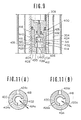
- Fig. 6 shows the detailed structure of a variable-damping-force shock absorber 12 employed in the first embodiment of the suspension control system according to the present invention.
- the shock absorber 12 generally comprises inner and outer hollow cylinders 20 and 22 arranged coaxially, and a piston 24 fitting flush within the hollow interior of the inner cylinder 20.
- the piston 24 defines upper and lower fluid chambers 26 and 28 within the inner cylinder 20.
- the inner and outer cylinders define an annular fluid reservoir chamber 30.
- the piston 24 is connected to the vehicle body (not shown) by means of a piston rod which is generally referred to by the reference number 32.
- the piston rod 32 comprises upper and lower segments 34 and 36.
- the upper segment 34 is formed with an axially extending through opening 38.
- the lower end of the through opening 38 opens into a recess 40 defined on the lower end of the upper segment 34.
- the lower segment 36 has an upper section 42 engageable to the recess 40 to define therein a hollow space 44.
- An actuator is disposed within the space 44.
- the actuator 46 is connected to the driver circuit 16 through a lead 48 extending through the through opening 38.
- the actuator 46 is associated with a movable valve body 50 which has a lower end extension 52 inserted into a guide opening 54 defined in the lower segment 36.
- the guide opening 54 extends across a fluid passage 56 defined through the lower segment 36 for fluid communication between the upper and lower fluid chambers 26 and 28.
- the fluid passage 56 serves as a bypass for flow-restrictive fluid passages 58 and 60 formed in the piston 24.
- the upper-end of the fluid passage 58 is closed by a resilient flow-restricting valve 62.
- the lower end of the fluid passage 60 is closed by a flow-restricting valve 64.
- the flow-restricting valve 62 and 64 serve as check valves for establishing one-way fluid communication in opposite directions.
- the flow-restriction valves 62 and 64 are biased toward the ends of the fluid passages 58 and 60, they open to allow fluid communication between the upper and lower fluid chambers 26 and 28 only when the fluid pressure difference between the upper and lower chambers 26 and 28 overcomes the effective pressure of the valves.
- the cross-sectional area of the fluid passages 58 and 60 and the set pressures of the fluid-restriction valves 60 and 62 determine the damping force produced in HIGH damping force mode.
- the cross-sectional area of the fluid passage 56 determines the drop-in the damping force in the LOW damping force mode in comparison with that in the HIGH damping force mode.
- the movable valve body 50 is normally biased upwards by means of a coil spring 51.
- the actuator 46 when the actuator 46 is not energized, the lower end section 52 of the valve body 50 is separated from the fluid passage 56 to allow fluid communication between the upper and lower chamber.
- the valve body 50 moves downwards against the resilient force of the coil spring 51 to block the fluid pasage 56 with the lower end extension 52.
- the damping force produced by the shock absorber 14 remains LOW.
- the fluid passage 56 is shut, fluid flow rate is reduced, thus increasing the damping force produced. Therefore, when the valve body 50 is shifted to the lowered position, the shock absorber works in HIGH damping force mode to produce a higher damping force against vertical shocks.
- a bottom valve 66 is installed between the lower fluid chamber 28 and the fluid reservoir chamber 30.
- the bottom valve 66 is secured to the lower end of the inner cylinder and includes fluid passages 68 and 70.
- the upper end of the fluid passage 68 is closed by a flow-restriction valve 72.
- the lower end of the fluid passage 70 is closed by a flow-restriction valve 74.
- the movable valve body 50 In the normal state wherein the control signal of the controller 100 remains LOW, the movable valve body 50 is held in its upper position by the effect of the spring force 51 so that the lower end extension 52 does not project into the fluid passage 56. Therefore, the fluid communication is established through both the fluid passage 56 and the applicable one of the flow-restricting fluid passages 58 and 60. As a result, the total flow restriction is relatively weak to allow the shock absorber to operate in SOFT mode.
- the driver signal generator 102 corresponding to each shock absorber 12 becomes active to energize the actuator 46.
- the actuator 46 drives the movable valve body 50 downward. This downward movement shifts the lower end of the extension 52 of the valve body 50 into the fluid passage 56 so as to block fluid communication between the upper and lower fluid chambers 26 and 28 via the fluid passage 56. Therefore, the fluid can flow between the upper and lower chambers 26 and 28 only through one of the fluid passages 58 and 60.
- the fluid flow restriction is, thus, increased, resulting in a greater damping force than is produced in the SOFT mode. In other words, the shock absorber 12 operates in HARD mode.
- Fig. 5 shows a suspension control program to be cyclically executed at a predetermined timing.
- the instantaneous value H of the road sensor signal Sr which is representative of a vehicle height from the road surface, is read out at a step 1102.
- an average value Have is calculated at a step 1104.
- average value H ave of the road sensor signal value H is calculated by adding a value derived from the instantaneous road sensor signal value H according to the following equation: where H ave0 is the average value of the road sensor signal value derived in the immediately preceding cycle of program execution.
- a step 1106 (H- H ave ) is calculated in order to derive a difference value D 1 .
- the derived difference value D 1 is compared with a predetermined reference value H ref which is representative of a harder suspension criteria, at a step 1108.
- H ref a predetermined reference value which is representative of a harder suspension criteria
- a higher vehicle height indicative flag FLHIGH is checked at a step 1110, which flag FLHIGH is to be set in the memory block 114 of RAM 106 when the difference value D 1 is equal to or greater than the reference value H ref .
- the higher vehicle height indicative flag FLHIGH is not set as checked at the step 1110, it is set at a step 1112.
- a value t of a timer 121 which is adapted to be set a predetermined t 0 and count down clock pulses from a clock generator 112, is checked whether the value t is zero, at a step 1114. If the timer value t is zero as checked at a step 1114, the timer 121 is set by the predetermined value t 0 at a step 1116.
- the difference value D 1 is smaller than the reference value H ref , the. higher vehicle height indicative flag FLHIGH is reset at a step 1118. Thereafter, (H ave - H) is calculated in order to derive a difference value D 2 at a step 1120. The derived difference value D 2 is compared with the reference H ref at a step 1122. When the difference value D 2 is equal to or greater than the reference value H ref' a lower vehicle height indicative flag FLLOW which is set/reset in a memory block 115 of RAM 106 is checked at a step 1124. When the flag FLLOW is not set as checked at the step 1124, the process goes to the step 1114.
- the lower vehicle height indicative flag FLLOW is reset at a step 1126. Thereafter, the timer value t is checked at a step 1128, whether the timer value t is zero. When the timer value t is zero as checked at the step 1128, then front and rear suspension control signals SFc and SRc are produced to operate the shock absorbers 12 into SOFT mode, at a step 1130. On the otherhand, when the timer value t is not zero as checked at the step 1128, the timer value t is decremented by 1 in response to clock pulse from the clock generator 112, at a step 1132.
- a counter value V of a vehicle speed counter 123 which is adapted to count pulse form vehicle speed indicative signals from the vehicle speed sensor 111, is read out at a step 1134. Derivation of the vehicle speed by counting the vehicle speed indicative signal from the vehicle speed sensor 111 is per se will known and need no detailed description.
- a front suspension timer threshold TF ref and a rear suspension timer threshold TR ref are derived at a step 1136.
- the front suspension timer threshold TF ref corresponds a possible elapsed time for the front wheels to reach a point after the road sensor passes over that point.
- the rear suspension timer threshold TR ref corresponds a possible elapsed time for the rear wheels to reach a point after the road sensor passes over that point. Therefore, the thresholds T F ref and TR ref are generally depend on the distance between the road sensor and the front and rear wheel axles. Since the elapsed time is variable depending upon the vehicle speed, the front and rear suspension timer thresholds TF ref and TR ref vary depending on the vehicle speed V. In practice, the front and rear suspension timer thresholds TF ref and TR ref would be derived by table look-up from tables 122 and 123 in terms of the vehicle speed counter value V.
- the elapsed time (TO - t) is then compared with the front suspension timer threshold TF ref at a step 1138. As long as the elapsed time value (TO - t) is smaller than the front suspension timer threshold TF ref' the front suspension control signal SFc to control the shock absorbers in the front suspension into SOFT mode is output, at a step 1140. Thereafter, the elapsed timer value (TO - t) is compared with the rear suspension timer threshold TR ref at a step 1142. Similarly to the above, as long as the elapsed time value is smaller than the rear suspension timer threshold, the rear suspension control signal SRc for operating the shock absorbers in the rear suspensions into SOFT mode is produced, at step 1144.
- the front suspension control signal SFc to operate the shock absorbers in the front suspension into HARD mode is produced at a step 1146.
- the rear suspension control signal SRc for operating the shock absorbers 12 in the rear suspension into HARD mode is produced at a step 1148.
- process When reset state of the higher vehicle height indicative flag FLHIGH is detected as checked at the step 1108 process also jumps to the step 1128. Also, when the timer value t as checked at the step 1114 is not zero, process jumps to the step 1128. Similarly, after setting the timer value t to the initial value T 0 at the step 1116, process jumps to the step 1128.
- the hardening timing of the front and rear suspensions are differed from the timing of detecting the bump as set forth above, and thus successfully adjusted so that each of the front and rear suspension is hardened upon the front and rear wheels passing over the bump. This assures riding comfort and the driving stability in more precise manner than that in the prior art.
- the line (a) represents road surface condition.
- the example illustrated is directed for substantially smooth road with a bump. While the vehicle is on the smooth road surface and thus the road sensor 200 does not detect the bump, the road sensor signal value H varies within the range defined by the reference value H ref' as represented by the line (b) in Fig. 6. Therefore, the timer value t is maintained zero.
- the front and rear suspension control signals S Fc and S Rc order SOFT mode of the shock absorbers 12f and 12r are provided to the shock absorbers 12f and 12r.
- the road sensor signal value H becomes to change at significant level so that the difference between the average value H ave become greater than the reference value H ref .
- This causes setting of the timer value t to the initial value to at a time t l .
- the front suspension timer threshold TF ref and the rear suspension timer threshold TR ref are derived interms of the vehicle speed indicative signal value V.
- the front suspension control signal S F changes its value to order HARD mode.
- the first embodiment of the suspension control systems as set forth above employs two-way variable damping characteristics shock absorber for varying the damping characteristics of the suspension between HARD mode and SOFT mode, it would be possible to employ shock absorbers which varies damping characteristics in more than two-way.
- the shock absorber which is variable of the damping characteristics in three-way i.e. HARD mode, MEDIUM mode and SOFT mode
- Figs. 8 to 11 show the modification of the variable-damping-characteristic shock absorber of Fig. 9.
- the shock absorber 12 can be operated in any of three modes, namely HARD mode, SOFT mode and MEDIUM mode, in the last of which damping characteristics intermediate to those of HARD mode and SOFT mode are achieved.
- the hydraulic shock absorber 12 has coaxial inner and outer cylinders 302 and 304. Top and bottom ends of the cylinders 302 and 304 are plugged with fittings 306 and 305.
- the fitting 306 includes a seal 307 which establishes a liquid-tight seal.
- a piston rod 308 extends through an opening 312 formed in the fitting 306 and is rigidly connected to a vehicle body (not shown) at its top end. The piston rod 308 is, in turn, connected to a piston 314 reciprocally housed within the inner cylinder 302 and defining upper and lower fluid chambers 316 and 318 therein.
- the piston 314 has fluid passages 320 and 322 connecting the upper and lower fluid chambers 316 and 318.
- the piston 314 also has annular grooves 324 and 326 along its upper and lower surfaces concentric about its axis.
- the upper end of the fluid passage 320 opens into the groove 324.
- the lower end of the fluid passage 322 opens into the groove 326.
- Upper and lower check valves 328 and 330 are provided opposite the grooves 324 and 326 respectively to close the grooves when in their closed positions.
- the lower end of the fluid passage 320 opens onto the lower surface of the piston at a point outside of the check valve 330.
- the upper end of the fluid passage 322 opens onto the upper surface of the piston at a point outside of the check valve 328.
- the fluid passage 322 is active during the piston expansion stroke, i.e. during rebound of the shock absorber. At this time, the check valve 323 prevents fluid flow through the fluid passage 320.
- the fluid passage 320 is active, allowing fluid flow from the lower fluid chamber 318 to the upper fluid chamber 316 and the fluid passage 322 is blocked by the check valve 330.
- the piston rod 308 has a hollow cylindrical shape so that a damping force adjusting mechanism, which will be referred to generally by the reference numeral "400" hereafter, can be housed therein.
- the damping force adjusting mechanism 400 includes a valve mechanism 402 for adjusting the cross-sectional area through which the working fluid can flow between the upper and lower chambers.
- the valve mechanism 402 allows three steps of variation of the damping force, i.e., HARD mode, MEDIUM mode and SOFT mode, the narrowest cross-sectional area representing the HARD mode, the widest the SOFT mode and intermediate the MEDIUM mode.
- the piston rod 308 defines an axially extending through opening 404 with the lower end opening into-the lower fluid chamber 318.
- a fitting 408 seals the lower end of the opening 404 of the piston rod and has axially extending through opening 410, the axis of which is parallel to the axis of the through opening 404 of the piston rod.
- the through openings 404 and 410 constitute a fluid path 412 extending through the piston rod.
- the piston rod 308 also has one or more radially extending orifices or openings 414 opening into the upper fluid chamber 316.
- the upper and lower fluid chambers 316 and 318 are in communication through the fluid path 412 and the radial orifices 414.
- a stationary valve member 416 with a flaring upper end 418 is inserted into the through opening 404 of the piston rod.
- the outer periphery of the flaring end 418 of the stationary valve member 416 is in sealing contact with the internal periphery of the through opening.
- the stationary valve member 416 has a portion 420 with a smaller diameter than that of the upper end 418 and so as to define an annular chamber 422 in conjunction with the inner periphery of the through opening 404 of the piston rod.
- the statioanry valve member 416 has two sets of radially extending orifices 424 and 426 and an internal space 428. The radially extending orifices 424 and 426 establish communication between the internal space 428 and the annular chamber 422.
- a movable or rotary valve member 430 is disposed within the internal space 428 of the stationary valve member 416.
- the outer periphery of the rotary valve member 430 slidingly and sealingly contacts the inner surface of the stationary valve member 416 to establish a liquid-tight seal therebetween.
- Radially extending orifices 432 and 434 are defined in the rotary valve member 430 at positions opposite the orifices 424 and 426 of the stationary valve member 416.
- the orifices 424 and 426 respectively include first, second and third orifices 424a, 424b, 424c, and 426a, 426b, and 426c.
- the first orifices 424a and 426b have the narrowest cross-sections and the orifices 432 and 434 are adapted to be in alignment with the first orifices to establish fluid communication between the upper and lower fluid chambers 316 and 318 in the case of the HARD mode.
- the third orifices 424c and 426c have the widest cross-sections and the orifices 432 and 434 are adapted to be in alignment with the third orifices in the case of the SOFT mode.
- the cross-sections of the second orifices 424b and 426c are intermediate those of the first and third orifices and the orifices 432 and 434 are adapted to align therewith in the case of the MEDIUM mode.
- a check valve 436 is provided within an internal space of the rotary valve member 430.
- the check valve 436 is normally biased towards a valve seat 438 by means of a bias spring 440 for allowing one-way fluid flow from the lower fluid chamber to the upper fluid chamber. This cause the bound damping force to be somewhat weaker than the rebound damping force.
- the rotary valve member 430 is associated with an electrically operable actuator such as an electrical step motor 442 through a differential gear unit 444 and an output shaft 446 as shown in Fig. 10 .
- a potentiometer 448 is associated with the output shaft 446.
- the potentiometer 448 includes a movable contact 450 with contactors 450a, 450b and 450c.
- the contactors 450a, 450b and 450c are adapted to slidingly contact stationary contact elements 452a, 452b and 452c of a stationary contact 452.
- the potentiometer 448 According to the electrical connections between the movable contact and the stationary contact, the potentiometer 448 produces a mode signal representative of the rotary valve position and thus indicative of the selected mode of the damping force adjusting- mechanism.
- the step motor 442 is electrically connected to a controller 100 to receive the control signal as a mode selector signal which drive the motor 442 through an angle corresponding to the rotary valve movement to the corresponding valve position.
- the potentiometer will return the mode signal as a feedback-signal to indicate the instantaneous valve position.
- controller 100 may be operated either in automatic mode or in manual mode.
- the shock absorber has a fluid reservoir chamber 332 between its inner and outer cylinders 302 and 304, which fluid reservoir chamber 332 is in communication with the lower fluid chamber 318 via the bottom fitting 305 described previously.
- the bottom fitting 305 may serve to produce damping force in cooperation with the piston and the damping force adjusting mechanism during bounding and rebounding motion of the vehicle.
- a relatively low pressure pneumatic chamber 336 is also defined between the inner and outer cylinders 302 and 304.
- Figs. 11 (A) and 11(B) show the case of the HARD mode.
- the orifice 432 of the rotary valve 430 is in alignment with the orifice 424a and the orifice 434 is in alignment with the orifice 426a.
- vehicle rebounding motion i.e., in the piston compression stroke
- the fluid flows from the upper fluid chamber 316 to the lower fluid chamber 318 though the orifice 426a.
- the fluid flows from the lower fluid chamber 318 to the upper fluid chamber 316 through orifices 424a and 426a. Since the first orifices 424a and 426a are the narrowest, the damping force produced in this mode is the highest among the three selectable modes.
- the orifices 432 and 434 of the rotary valve member 430 are respectively in alignment with the second orifices 424b and 426b.
- the orifices 432 and 434 align with the third orifices 424c and 426c, respectively to cause fluid flow. Since the third orifices 424c and 426c are the widest of the three sets, as described above, the damping force created in this SOFT mode is the lowest.
- the electric step motor 442 is connected to the controller 100 through the driver circuit 16.
- the controller 100 selects any appropriate damping force state in accordance with detected road surface conditions but in this case produces a three-way control signal for actuating the shock absorber to one of the SOFT, MEDIUM and HARD modes.
- the driver circuit 16 is responsive to the control signal to drive the step motor 442 to operate the rotary valve member 430 to the corresponding valve position.
- Figs. 12 to 14 show the structure of a roll stabilizer 530 to be controlled by the first or second embodiment of the suspension control system as set forth above.
- the roll stabilizer 530 comprises a transverse bar section 532 and a pair of parallel bar sections 534 and 536.
- the transverse bar section 532 extends essentially perpendicular to the vehicle axis and has a circular cross-section.
- the transverse bar section 532 is connected to hollow cylindrical bearing sections 538 and 540 at both ends.
- the parallel bar sections 534 and 536 have end segments 542 and 544 of circular cross-section adapted to rotatably engage the bearings 538 and 540 of the transverse bar section 532.
- the parallel bar sections 534 and 536 also have rectangular cross-section major sections 546 and 548, each of which has one end 550 and 552 connected to a suspension arm 551 through a connecting rod 553 which allows free rotation of the associated bar 534 or 536.
- the cylindrical cross-section end segments 542 and 544 of the parallel bar sections 534 and 536 extend beyond the ends of the bearing portion 538 and 540.
- Link plates 554 and 556 are rigidly fitted onto the protruding ends of the parallel bar sections 534 and 536.
- the link plates 554 and 556 are rotatable about the bearing sections 538 and 540 together with the parallel bar sections 534 and 536.
- the link plates are connected to each other through a linkage 558.
- the link plate 554 is associated with an actuator 560 through an actuation rod 562 engaging an elongated opening 564 of the link plate 554.
- the actuator 560 may comprise an electromagnetically operative solenoid.
- the actuator is adapted to be energized by a control signal fed from a controller 100 to rotate the link plate 554 along with the parallel bar section 534 through 90° from the shown neutral position.
- the link plate 556 is also rotated according to rotation of the-link plate 554 to pivot the parallel bar 536 through 90° within the bearing section 540.
- the parallel bar sections 534 and 536 lie with their wider sides 534w (536w) horizontal.
- the actuator 560 is energized, the parallel bar sections 534 and 536 are rotated to lie with their shorter sides 534s (536s) horizontal, as shown in phantom line in Fig. 12.
- the bending stress on the parallel bar sections 534 and 536 is increased, i.e., the torsion on the transverse bar section 532 of the stabilizer is increase.
- the roll-stabilizer 530 is normally arranged so that the wider sides 534W and 536W of the parallel bar sections 534 and 536 lie horizontal. As set forth above, since the resistance of the parallel bar sections 534 and 536 to bounding and rebounding of the vehicle wheel is relatively weak in this position, the stiffness of the suspension remains low to provide good riding comfort. This roll-stabilizer 530 is held in this position as long as the road surface condition indicative signal value remains less than the threshold value which is also derived in accordance with the vehicle speed.
- the actuator 560 When the steering angle change matches or exceeds the threshold value, the actuator 560 is energized to rotate the parallel bar sections 534 and 536 through 90° to align the shorter sides 534S and 536S horizontally. As a result, a greater resistance is exerted against bounding and rebounding of the vehicle wheel to successfully suppress rolling motion of the vehicle body.
- controlling the stiffness of the roll-stabilizer set forth above can also achieve roll-suppressive suspension control comparable to that of the first embodiment.
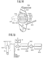
- Fig. 15 shows another arrangement of the automotive suspension system to which the control system according to the present invention is applicable.
- the pneumatic chamber 600 is connected to a pressurized pneumatic fluid source 602.
- the fluid source 602 comprises a compressor 604 for pressurizing a fluid such as air, a reservoir tank 606 connected to the compressor 604 through an induction valve 608, and a pressure control valve 610.
- the pressure control valve 610 connected to the driver circuit 16 to be controlled thereby.
- the fluid reservoir 606 is connected to the compressor 604 to receive the pressurized fluid.
- the fluid reservoir 606 is open to atmosphere to decrease the fluid pressure in the ventilation mode of the induction valve.
- the pressure control valve 610 is co-operative with the induction valve 608 to adjust the fluid pressure in the pneumatic chamber 600 in accordance with vehicle driving conditions.
- the driver ' circuit 16 may be connected to the control system of any of the first embodiment so that it is activated in response to road roughness.
- the pressure control valve 610 closes to block pneumatic fluid communication between the pneumatic chamber 600 and the fluid reservoir 606.
- the effective volume of the pneumatic chamber 600 corresponds to that of the pneumatic chamber.
- the damping characteristics due to the pneumatic pressure in the pneumatic chamber is related to the effective volume of the pneumatic chamber and a smaller volume is achieved by blocking fluid communication between the pneumatic chamber and the fluid reservoir, the pneumatic chamber becomes relatively rigid in this case, providing a larger damping force in response to the rough road which causes relatively low-frequency of vibration on the vehicle body as detected by the manner as set out with respect to the first embodiment.
- the effective volume becomes equal to the sum of the volumes of the pneumatic chamber and the fluid reservoir.
- Road surface condition dependent suspension control can also be achieved with this suspension system.
- the pressure control valve 610 is closed to block fluid communication between the pneumatic chamber 600 and the reservoir in order to increase the stiffness of the strut assembly and so produce a greater damping force with which to suppress vibration of the vehicle body.
- the pressure control valve 610 remains open, allowing fluid communication between the pneumatic chamber and the reservoir chamber. As a result, sufficiently soft-shock-absorbing characteristics can be provided to ensure good riding comfort.
- the vehicular suspension system can provide both riding comfort and good drivability by controlling hardness of the suspension depending upon the road surface conditions.
Abstract
Description
- The present invention generally comprises a bouncing suppressive suspension control system which suppressive bouncing of the vehicle occuring when the vehicle passes over a bump, manhole projecting from the road surface, hole and so forth which causes temporary bounding and/or rebounding motion on the vehicle and which will be referred to hereafter as "bump". More specifically, the invention relates to a suspension control system which assure riding comfort by precisely performing bouncing suppressive suspension control to vary damping characteristics of front and rear suspension systems independently of each other.
- Various uses of road preview sensors have been proposed and developed. For example, SAE Technical Paper Series -Nos. 630750 and 800520, respectively published on October, 1968 and February, 1980 show road preview sensors for use in suspension systems for obtaining optimum riding comfort and drivability. In addition, Japanese Patent First Publication No. 57-172808, published on October 23, 1982 discloses a vehicle height control system .which includes a sensor which detects rough road conditions and adjusts the vehicle height level depending upon road surface conditions. A vehicle height or level sensor is employed in the disclosed vehicle height control system for monitoring the relative displacement between the vehicle body and wheel axle. The output of the vehicle level sensor is compared with a reference level, which serves as a rough road criterion, and adjusts the vehicle height according to the result of judgement of the road surface conditions.
- On another example, Japanese Patent First Publication' No. 58-30542, published on February 23, 1983, discloses a variable damping force shock absorber with damping characteristics varying in accordance with vehicle driving conditons. In the disclosed system, the magnitude of relative displacement between the vehicle body and wheel axle is measured and a vehicle height variation indicative signal is derived from the measured displacement and the instantaneous vehicle speed. The vehicle height variation indicative signal value is compared with a reference value which serves as a staff suspension criterion for adjustment of the damping characteristics of the shock absorber in accordance therewith.
- On the other hand, Published Japanese Patent Application (Tokkai) Sho. 56-42739 discloses a suspension control system which controls the damping force produced in response to rolling forces depending upon vehicle speed and steering adjustments. The damping force is so controlled as to be HIGH when the vehicle speed is higher than a set speed and the steering adjustments through greater than a predetermined angle are performed. In addition, the owner of the present application has already disclosed a suspension control system in Published Japanese Utility Model Application (Jikkai) Sho. 56-147107. In this system, the damping force produced by a suspension shock absorber is adjusted between HIGH and LOW levels depending upon the vehicle speed, the magnitude of steering adjustments and the angular velocity of steering adjustments.
- In such prior art, road condition dependent suspension control has been performed according to the road surface condition indicative parameter. Such prior art suspension control systems achieves driving stability of the vehicle and riding comfort in some extent. However, in the prior it has been difficult to perform road condition dependent suspension control in precise manner so as to adapt damping characteristics or stiffness of the suspension precisely depending upon the road surface condition.
- Typical defect or drawback of the conventional systems have been found while the vehicle passes over a bump, manhole projecting from the road surface or a hole formed in the road. In such case, it is required to harden or stiffen the suspension for maintain damping characteristics hard enough for driving stability. Such demand for hard suspension temporarily or momentally occurs when passing over the bump, manhole or hole on the road surface and thereafter terminates. Since the conventional suspension control system controls damping characteristics solely depending upon amplitude of unevenness of the vehicle, such bump, manhole, hole on the road surface cannot be distinguished from undulation, gravel or rough road.
- Furthermore, since the conventional control system controls the suspension to harden the damping characteristics of the suspension when magnitude of unevenness with electronical and mechanical lag time, change of damping characteristics delays for a certain period. This lag time prevents the conventional suspension control systems from performing control precisely adapted to the road surface condition. In addition, when the road surface sensor is provided at a position corresponding to either of front and rear suspension, lag will cause substantial delay of change of damping characteristics to harden the suspension after passing over the bump, manhole or hole. On the other hand, when the road condition sensor is provided at the front end of the vehicle, hardening of the suspension occurs in advance of passing the bump, manhole or hole. This is still not satisfactory in controlling the suspension in precise manner.
- Therefore, it is an object of the invention to provide a suspension control system which can precisely adapt damping characteristics to the road condition.
- Another and more specific object of the invention is to provide a suspension control system which assures riding comfort even when the vehicle passes over bump, manhole, hole and so forth.
- In order to accomplish the aforementioned and other objects, a suspension control system, according to the invention, includes a road sensor which produces a road condition indicative signal. A controller is adapted to recognize bump, manhole, hole and so forth which causes temporary bounding and rebounding motion for the vehicle, on the basis of the road condition indicative signal from the road sensor. The controller produces a control signal to harden damping characteristics of suspension when -bump, manhole, hole and so forth is detected with a given delay time. The delay time for changing damping characteristics is different at the front and rear suspension from each other so that each of the front and rear suspension can be stiffened at a good timing.
- In practice, the suspension control system varies a criteria of bounding magnitude across which damping characteristics is varied, depending upon a vehicle speed. For instance, when vehicle speed increases, the bounding magnitude criteria is lowered to increase sensing ability of the bounding for assure driving stability.
- The suspension control system further adapted to maintain the damping characteristics of the suspension at hardened level for a given period after passing over the bump. This will successfully prevent the suspension control system from causing hunting while passing through undulation road, gravel and so forth. According to one aspect of the invention, a suspension control system for a vehicle comprises front and rear suspension systems variable of damping characteristics at least in first mode where relatively low damping characteristics is obtained and a second mode where relatively high damping characteristics is obtained, the front and rear suspension systems being variable of the operation mode independently of each other, a road sensor monitoring road surface condition and producing a road condition indicative signal, a controller deriving operation mode of the front and rear suspensions on the basis of the road condition indicative signal to produce control signals for controlling the front and rear suspensions independently of each other, the controller being responsive to the road condition indicative signal having a value greater than a predetermined threshold value to output the control signal for controlling the- front suspension to the second mode with a given first delay time and output the control signal for controlling the rear suspension to the second mode with a given second delay time, which first and second delay time are determined depending upon dimensional relationship of the road sensor, the front suspension and the rear suspension.
- According to another aspect of the invention, a method for controlling damping characteristics of front and rear vehicular suspension systems, each of which is variable of damping characteristics according to a preselected suspension control parameter, comprising the steps of monitoring road surface condition and producing a road surface indicative signal, detecting irregularity of the road surface at a magnitude greater than a predetermined criteria, controlling damping characteristics of the front suspension system to the first mode with a given first delay time from a time at which the irregularity of the road surface of the greater magnitude than the criteria is detected, and controlling damping characteristics of the rear suspension system to the first mode with a given second delay time from a time at which the irregularity of the road surface of the greater magnitude than the criteria is detected.
- The present invention will be understood more fully from the detailed description given herebelow and from the accompanying drawings of the preferred embodiments of the invention, which, however, should not be taken to limit the invention to the specific embodiments but are for explanation and understanding only.
- The following drawing, throughout which like numerals refer to like elements, may be of assistance in understanding the concepts behind the present invention and the structure, function and purpose of some preferred embodiments thereof:
- In the drawings:
- Fig. 1 is a perspective view of an automotive vehicle with a typical vehicular suspension system and a first preferred embodiment of a suspension control system in accordance with the present invention;
- Fig. 2 is a block diagram of the suspension control system of Fig. 1;
- Fig. 3 is a more detailed block diagram of the road sensor of Fig. 3;
- Fig. 4 is a flowchart of a road sensor timing control program executed by the controller of Figs. 2 and 3;
- Fig. 5 is a flowchart of a suspension control program to be executed by the first embodiment of suspension control system according to the invention;
- Fig. 6 is a longitudinal section through a shock absorber used in the first preferred embodiment;
- Fig. 7 is a timing chart showing operation of the first embodiment of the suspension control system;
- Fig. 8 is a longitudinal section of a modified shock absorber which is applicable for the first embodiment of the suspension control system of the invention;
- Fig. 9 is a partial longitudinal section through a modified shock absorber;
- Fig. 10 is an enlarged longitudinal section through the damping force adjusting mechanism of Fig. 9;
- Fig. ll(A) and 11(B) are cross-sections through the mechanism shown in Fig. 9 at positions revealing the three possible fluid flow paths;
- Fig. 12 is a fragmentary perspective view of a vehicular roll stabilizer in a suspension system, to which the present invention of a suspension control is applicable;
- Fig. 13 is an enlarged side elevation showing major part of the roll stabilizer of Fig. 14;
- Fig. 14 is a cross-section taken along line A - A of Fig. 12; and
- Fig. 15 is a schematic diagram of the third embodiment of a suspension control system in accordance with the present invention.
- Referring now to the drawings, particularly to Fig. 1, the preferred embodiment of an electronic suspension control system in accordance with the present invention generally comprises suspension strut assemblies 10- in front and rear suspension, each including a shock absorber 12 with variable shock-absorbing characteristics and a
controller 100 adapted to produce a control signal for actuating an actuator (not shown in Fig. 1) in each shock absorber 12 in order to the adjust the shock-absorbing characteristics in accordance with the vehicle driving condition. - In practice, the preferred embodiment of the suspension control system is adapted to operate the actuators of the shock absorbers 12f in the front suspension and the actuators of the shock absorbes 12r in the rear suspension independently of each other. For this, the
controller 100 outputs different two control signals for independently controlling the actuators of the shock absorbers 12f and 12r independently of each other. The control signal for controlling the actuator of the shock absorber 12f of the front suspension will be referred to hereafter as "front suspension control signal SFC". The control signal for controlling the actuator of the shock absorber 12r of the rear suspension will be referred to hereafter as "rear suspension control signal SRc". - It should be appreciated that the term "shock-absorbing characteristics" used throughout the disclosure refers to the quantitative degree to which a shock absorber produces damping force or spring force against bounding and rebounding motion of the vehicle body as a sprung mass and the road wheel assembly as unsprung mass, and pitching and rolling movement of the vehicle body relative to the road wheel assembly. In practice, the shock-absorbing characteristics can be controlled in various ways based on flow restriction between shock absorber working chambers disposed in shock absorber cylinders. In the shown embodiment, the flow restriction is variable by means of a flow control valve disposed within a reciprocable piston separating the chambers. The preferred embodiment described herebelow employs a shock absorber with two-way variable shock-absorbing characteristics, i.e. HARD mode and SOFT mode. Obviously, in HARD mode, the damping force generated in response to bounding or rebounding shock applied to the vehicle is greater than in SOFT mode. However, the shown embodiment is to be considered merely as an example for facilitating better understanding of the invention and simplification of the disclosure. In fact, shock absorbers which operate in three modes, i.e. HARD mode, SOFT mode and INTERMEDIATE or MEDIUM mode, are also applicable to the preferred embodiment of the suspension control system according to the invention. Some possible modifications to the shock absorber will be disclosed together with the preferred shock absorber design given later.
- It should be further noted that, throughout the disclosure, the work "bump" represents any irregularity on the road, such as bump as a projection, a manhole projecting from the road surface, hole and so forth, which causes temporary bouncing motion of the vehicle.
- Returning to Fig. 1, the
controller 100 is connected to aroad surface sensor 200 which produces a sensor signal Sr indicative of road surface conditions, which will be referred to hereinafter as "road sensor signal Sr". Thecontroller 100 may also be connected to avehicle speed sensor 201. In practice, thevehicle speed sensor 201 is adapted to monitor rotation speed of a propeller shaft or drive shaft for deriving a vehicle speed indicative signal S in- a per se well known manner. Thecontroller 100 is also connected to other sensors, such as a brake switch, etc., in order to receive the sensor signals indicative of the suspension control parameters. Thecontroller 100 is, in turn, connected todriver signal generators 102 which are responsive to the front and rear control signals SFc and SRc from the controller, which control signals SFc and S RC can assume either of two states, namely HIGH and LOW. Thedriver signal generator 102 produces a drive signal Sd which actuates the shock absorber to one of the HARD and SOFT modes. - The
controller 100 is responsive to the road sensor signal Sr and the vehicle speed indicative signal S to produce the front and rear control signals SFc and SRc for switching the shock absorber between HARD mode and SOFT mode. - The
controller 100 is also connected to a manually operable switch 202 for allowing operation mode of the control system, which switch will be referred to hereafter as "auto/manual switch". The auto/manual witch 202 may be switched between MANUAL SOFT, MANUAL HARD and AUTO modes. In the MANUAL SOFT and MANUAL HARD modes, damping characteristics of the front and rear suspensions are fixed at SOFT or HARD mode irrespective of driving condition. - Fig. 2 shows the preferred first embodiment of the suspension control
system including controller 100 which generally comprises a microprocessor. In practice, the microprocessor performs control operations not only depending upon the road surface conditions but also depending upon vehicle speed, other vehicle driving conditions, such as vehicle acceleration, and other preselected suspension control parameters. - The
microprocessor 100 generally comprises aninput interface 102,CPU 104,RAM 106,ROM 108 andoutput interface 110. In the shown embodiment, themicroprocessor 100 is connected to theroad sensor 200 via theinput interface 102. Themicroprocessor 100 is also connected for input from aclock generator 112. The road sensor, in the shown embodiment, comprises an ultra-sonic sensor, construction and operation of which will be described herebelow. Theultra-sonic sensor 200 is associated with thecontroller 100. Theoutput interface 110 of themicroprocessor 100 is connected for output of control signal Sc to each of the driver signal generators. - As shown in Fig. 3, the
ultra-sonic sensor 200 comprises generally anultra-sonic wave transmitter 230 and a reflectedultra-sonic wave receiver 232. Thetransmitter 230 is associated with thecontroller 100 to receive therefrom a trigger signal STr at a given timing. Thetransmitter 230 includes anultra-sonic oscillator 234 and an ultra-sonicwave transmitting section 236. Theultra-sonic oscillator 234 is responsive to the trigger signal STr from thecontroller 100, which is issued periodically or intermittently, to transmit or discharge ultra-sonic waves through thetransmitter section 236 toward the road surface. - The ultra-sonic waves reflected by the road surface are received by a
receiver section 238 of thereceiver 232. Thereceiver section 238 produces a receiver signal S Rc having value varying in accordance with the amplitude of the received ultra-sonic waves. Thereceiver section 238 is connected to anamplifier 240 to supply the receiver signal -SRc to the latter. The receiver signal SRc is amplified by theamplifier 240 and transmitted to a rectifier 242. The rectifier 242 is connected to the band-pass filters 204 and 206 as set forth above, through ashaping circuit 244. The rectifier 242 is also connected to a peak-hold circuit 246 which holds the peak value of the receiver signal. The peak-hold circuit 246 produces an analog peak-value-indicative signal Spe having a value proportional to the held peak value. The peak-hold circuit 246 is connected for output to thecontroller 100 via an analog-to-digital converter 248. The analog-to-digital converter 248 outputs a binary signal indicative of the peak-value-indicative signal value to thecontroller 100. - The peak-
hold circuit 246 is also connected to thecontroller 100 to receive the trigger signal STr. The peak-hold circuit 246 is responsive -to the trigger signal from the controller to clear the currently held value. - Fig. 4 shows a timing control program executed by the
controller 100 for controlling the trigger timing of theultra-sonic sensor 200. - At the initial stage of execution of the timing control program, a trigger-signal-output- indicative flag FTr in a memory block 120 of RAM is checked at a
step 1002. The trigger signal FTr is set when the trigger signal is output through theoutput interface 110 to thetransmitter 230 and is reset when the trigger signal is not being output. - If the trigger signal-indicative flag FTr is set when checked at the
step 1002, then the timer value T1 of atimer 122 in RAM is latched at astep 1004. Thetimer 122 continuously counts clock pulses from theclock generator 112. A trigger-signal-ON-time indicative time value t1 is added to the latched timer value T1 at astep 1006. The resultant value (T1 + tl) , which serves as a trigger-signal-OFF time value, is transferred to and stored in a T2-register 124 inRAM 106, at astep 1008. Then the flag FTr is set at astep 1010. A HIGH-level output is applied to the output interface as trigger signal STr at astep 1012. - During the period t1 starting from the time T 1, the potential at the output interface is held HIGH to continue application of the trigger signal STr to the
transmitter 230. Thetimer 124 continues counting the clock pulses and produces a T1-timer signal after period t1 which serves as a trigger signal for the timing control program. - In response to the T1-timer signal at time T2 marking the end of the period t1, the timing control program is executed again. Since the trigger signal-indicative flag FTr was set at the
step 1010 in the previous cycle of program execution, the answer at thestep 1002 becomes "NO". Thus, control passes to astep 1014 in which the timer value T2 of thesecond timer 125 is accessed inRAM 106. Similarly to the first-mentionedtimer 124, thetimer 125 continuously counts clock pulses from theclock generator 112. An OFF-interval-indicative time data t2 is added to the latched timer value T2 at astep 1016. The time data t2 has a value corresponding to a predetermined interval between successive trigger signals. The resultant time value (T2 + t2) is stored in the T1-timer 124 ofRAM 106 at astep 1018. Then, the flag FTr is reset at astep 1020. After thestep 1020, the output level at the output interface drops to LOW to terminate transmission of the trigger signal to the transmitter, at astep 1022. - The detailed structure and operation of the aforementioned preferred embodiment of the ultra-sonic sensor has been disclosed in the co-pending U.S. Patent Application Serial No. 650,705, filed September 14, 1984. The disclosure of the above-identified U.S. Patent Application Serial No. 650,705 is hereby incorporated by reference for the sake of disclosure.
- Fig. 6 shows the detailed structure of a variable-damping-
force shock absorber 12 employed in the first embodiment of the suspension control system according to the present invention. Theshock absorber 12 generally comprises inner and outerhollow cylinders piston 24 fitting flush within the hollow interior of theinner cylinder 20. Thepiston 24 defines upper and lowerfluid chambers inner cylinder 20. The inner and outer cylinders define an annularfluid reservoir chamber 30. - The
piston 24 is connected to the vehicle body (not shown) by means of a piston rod which is generally referred to by thereference number 32. Thepiston rod 32 comprises upper andlower segments upper segment 34 is formed with an axially extending throughopening 38. The lower end of the throughopening 38 opens into arecess 40 defined on the lower end of theupper segment 34. On the other hand, thelower segment 36 has anupper section 42 engageable to therecess 40 to define therein ahollow space 44. An actuator is disposed within thespace 44. Theactuator 46 is connected to thedriver circuit 16 through a lead 48 extending through the throughopening 38. Theactuator 46 is associated with amovable valve body 50 which has alower end extension 52 inserted into aguide opening 54 defined in thelower segment 36. Theguide opening 54 extends across afluid passage 56 defined through thelower segment 36 for fluid communication between the upper and lowerfluid chambers - The
fluid passage 56 serves as a bypass for flow-restrictive fluid passages piston 24. The upper-end of thefluid passage 58 is closed by a resilient flow-restrictingvalve 62. Similarly, the lower end of thefluid passage 60 is closed by a flow-restrictingvalve 64. The flow-restrictingvalve restriction valves fluid passages fluid chambers lower chambers - The cross-sectional area of the
fluid passages restriction valves fluid passage 56 determines the drop-in the damping force in the LOW damping force mode in comparison with that in the HIGH damping force mode. - The
movable valve body 50 is normally biased upwards by means of acoil spring 51. As a result, when theactuator 46 is not energized, thelower end section 52 of thevalve body 50 is separated from thefluid passage 56 to allow fluid communication between the upper and lower chamber. When theactuator 46 is energized,thevalve body 50 moves downwards against the resilient force of thecoil spring 51 to block thefluid pasage 56 with thelower end extension 52. As a result, fluid communication between the upper and lowerfluid chambers fluid passage 56 is blocked. When fluid communication through the fluid passage is permitted, the damping force produced by theshock absorber 14 remains LOW. On the other hand, when thefluid passage 56 is shut, fluid flow rate is reduced, thus increasing the damping force produced. Therefore, when thevalve body 50 is shifted to the lowered position, the shock absorber works in HIGH damping force mode to produce a higher damping force against vertical shocks. - A
bottom valve 66 is installed between thelower fluid chamber 28 and thefluid reservoir chamber 30. Thebottom valve 66 is secured to the lower end of the inner cylinder and includesfluid passages fluid passage 68 is closed by a flow-restriction valve 72. The lower end of thefluid passage 70 is closed by a flow-restriction valve 74. - In the normal state wherein the control signal of the
controller 100 remains LOW, themovable valve body 50 is held in its upper position by the effect of thespring force 51 so that thelower end extension 52 does not project into thefluid passage 56. Therefore, the fluid communication is established through both thefluid passage 56 and the applicable one of the flow-restrictingfluid passages - In response to a HIGH-level control signal from the
controller 100, thedriver signal generator 102 corresponding to eachshock absorber 12 becomes active to energize theactuator 46. Theactuator 46 drives themovable valve body 50 downward. This downward movement shifts the lower end of theextension 52 of thevalve body 50 into thefluid passage 56 so as to block fluid communication between the upper and lowerfluid chambers fluid passage 56. Therefore, the fluid can flow between the upper andlower chambers fluid passages shock absorber 12 operates in HARD mode. - Operation of the aforementioned first embodiment of the suspension control system in accordance with the present invention will be described herebelow with reference Fig. 5.
- Fig. 5 shows a suspension control program to be cyclically executed at a predetermined timing. Immediately after starting execution, the instantaneous value H of the road sensor signal Sr, which is representative of a vehicle height from the road surface, is read out at a
step 1102. Then, an average value Have is calculated at astep 1104. - In practice, average value H ave of the road sensor signal value H is calculated by adding a value derived from the instantaneous road sensor signal value H according to the following equation:

where H ave0 is the average value of the road sensor signal value derived in the immediately preceding cycle of program execution. - At a
step 1106, (H- Have) is calculated in order to derive a difference value D1. The derived difference value D1 is compared with a predetermined reference value Href which is representative of a harder suspension criteria, at astep 1108. When the difference value D1 is equal to or greater than the reference value Href, a higher vehicle height indicative flag FLHIGH is checked at astep 1110, which flag FLHIGH is to be set in thememory block 114 ofRAM 106 when the difference value D1 is equal to or greater than the reference value Href. When the higher vehicle height indicative flag FLHIGH is not set as checked at thestep 1110, it is set at astep 1112. Thereafter, a value t of atimer 121 which is adapted to be set a predetermined t0 and count down clock pulses from aclock generator 112, is checked whether the value t is zero, at astep 1114. If the timer value t is zero as checked at astep 1114, thetimer 121 is set by the predetermined value t0 at astep 1116. - On the other hand, when the difference value D1 is smaller than the reference value Href, the. higher vehicle height indicative flag FLHIGH is reset at a
step 1118. Thereafter, (Have - H) is calculated in order to derive a difference value D2 at astep 1120. The derived difference value D2 is compared with the reference Href at astep 1122. When the difference value D2 is equal to or greater than the reference value H ref' a lower vehicle height indicative flag FLLOW which is set/reset in amemory block 115 ofRAM 106 is checked at astep 1124. When the flag FLLOW is not set as checked at thestep 1124, the process goes to thestep 1114. - If the difference value D2 is smaller than the reference value Href as checked at the
step 1120, the lower vehicle height indicative flag FLLOW is reset at astep 1126. Thereafter, the timer value t is checked at astep 1128, whether the timer value t is zero. When the timer value t is zero as checked at thestep 1128, then front and rear suspension control signals SFc and SRc are produced to operate theshock absorbers 12 into SOFT mode, at astep 1130. On the otherhand, when the timer value t is not zero as checked at thestep 1128, the timer value t is decremented by 1 in response to clock pulse from theclock generator 112, at astep 1132. - Thereafter, a counter value V of a
vehicle speed counter 123 which is adapted to count pulse form vehicle speed indicative signals from the vehicle speed sensor 111, is read out at astep 1134. Derivation of the vehicle speed by counting the vehicle speed indicative signal from the vehicle speed sensor 111 is per se will known and need no detailed description. - On the basis of the counter value V, a front suspension timer threshold TF ref and a rear suspension timer threshold TRref are derived at a
step 1136. It should be noted that the front suspension timer threshold TFref corresponds a possible elapsed time for the front wheels to reach a point after the road sensor passes over that point. Similarly, the rear suspension timer threshold TR ref corresponds a possible elapsed time for the rear wheels to reach a point after the road sensor passes over that point. Therefore, the thresholds TF ref and TRref are generally depend on the distance between the road sensor and the front and rear wheel axles. Since the elapsed time is variable depending upon the vehicle speed, the front and rear suspension timer thresholds TFref and TRref vary depending on the vehicle speed V. In practice, the front and rear suspension timer thresholds TFref and TRref would be derived by table look-up from tables 122 and 123 in terms of the vehicle speed counter value V. - The elapsed time (TO - t) is then compared with the front suspension timer threshold TFref at a
step 1138. As long as the elapsed time value (TO - t) is smaller than the front suspension timer threshold TFref' the front suspension control signal SFc to control the shock absorbers in the front suspension into SOFT mode is output, at astep 1140. Thereafter, the elapsed timer value (TO - t) is compared with the rear suspension timer threshold TRref at astep 1142. Similarly to the above, as long as the elapsed time value is smaller than the rear suspension timer threshold, the rear suspension control signal SRc for operating the shock absorbers in the rear suspensions into SOFT mode is produced, atstep 1144. - If the elapsed timer value (T0 - t) becomes equal to or greater than the front suspension timer threshold TF ref -as checked at the
step 1138, the front suspension control signal SFc to operate the shock absorbers in the front suspension into HARD mode is produced at astep 1146. Similarly, when the elapsed time becomes equal to or greater than the rear suspension timer threshold TRref as checked at thestep 1140, the rear suspension control signal SRc for operating theshock absorbers 12 in the rear suspension into HARD mode, is produced at astep 1148. - When reset state of the higher vehicle height indicative flag FLHIGH is detected as checked at the
step 1108 process also jumps to thestep 1128. Also, when the timer value t as checked at thestep 1114 is not zero, process jumps to thestep 1128. Similarly, after setting the timer value t to the initial value T0 at thestep 1116, process jumps to thestep 1128. - As will be appreciated herefrom; the hardening timing of the front and rear suspensions are differed from the timing of detecting the bump as set forth above, and thus successfully adjusted so that each of the front and rear suspension is hardened upon the front and rear wheels passing over the bump. This assures riding comfort and the driving stability in more precise manner than that in the prior art.
- It should be noted that it would be preferable to provide another delay time for switching mode of the shock absorbers from the HARD mode to SOFT mode after passing the bump for preventing the control system from causing hunting on the undulation road, gravel road and so forth.
- The suspension control operation to be taken place by the aforementioned first embodiment of the suspension control system according to the invention will be described herebelow with reference to Fig. 7. In Fig. 7, the line (a) represents road surface condition. As will be appreciated from the line (a) the example illustrated is directed for substantially smooth road with a bump. While the vehicle is on the smooth road surface and thus the
road sensor 200 does not detect the bump, the road sensor signal value H varies within the range defined by the reference value Href' as represented by the line (b) in Fig. 6. Therefore, the timer value t is maintained zero. As a result, the front and rear suspension control signals SFc and SRc order SOFT mode of the shock absorbers 12f and 12r. - When the vehicle approaches the bump and the
road sensor 200 detects. The road sensor signal value H becomes to change at significant level so that the difference between the average value H ave become greater than the reference value H ref. This causes setting of the timer value t to the initial value to at a time tl. In response to setting of the timer value to t0' the front suspension timer threshold TFref and the rear suspension timer threshold TR ref are derived interms of the vehicle speed indicative signal value V. When the timer value t is decremented to the value qual to or smaller than front suspension timer threshold TFref at a time t2' the front suspension control signal SF, changes its value to order HARD mode. As appreciated from Fig. 6, since the rear suspension timer threshold TRref defines longer elapsed time than that of the front suspension timer threshold TFref' the rear suspension control signal SRc remains unchanged to maintain SOFT mode for the rear suspension. At a time t3, the timer value t is decremented below the rear suspension timer threshold TRref. Then, the rear suspension control signal SRc is changed to order HARD mode. - When the timer value t is decremented to zero at a time t4, the front and rear suspension control signals SFC and SRc changes to order SOFT mode.
- Though the first embodiment of the suspension control systems as set forth above employs two-way variable damping characteristics shock absorber for varying the damping characteristics of the suspension between HARD mode and SOFT mode, it would be possible to employ shock absorbers which varies damping characteristics in more than two-way. For example, the shock absorber which is variable of the damping characteristics in three-way, i.e. HARD mode, MEDIUM mode and SOFT mode, is applicable for the foregoing first embodiment of the suspension control system. Figs. 8 to 11 show the modification of the variable-damping-characteristic shock absorber of Fig. 9. In this modification, the
shock absorber 12 can be operated in any of three modes, namely HARD mode, SOFT mode and MEDIUM mode, in the last of which damping characteristics intermediate to those of HARD mode and SOFT mode are achieved. - The
hydraulic shock absorber 12 has coaxial inner andouter cylinders cylinders fittings 306 and 305. The fitting 306 includes aseal 307 which establishes a liquid-tight seal. Apiston rod 308 extends through anopening 312 formed in the fitting 306 and is rigidly connected to a vehicle body (not shown) at its top end. Thepiston rod 308 is, in turn, connected to apiston 314 reciprocally housed within theinner cylinder 302 and defining upper and lowerfluid chambers - The
piston 314 hasfluid passages fluid chambers piston 314 also hasannular grooves fluid passage 320 opens into thegroove 324. On the other hand, the lower end of thefluid passage 322 opens into thegroove 326. Upper andlower check valves grooves fluid passage 320 opens onto the lower surface of the piston at a point outside of thecheck valve 330. Likewise the upper end of thefluid passage 322 opens onto the upper surface of the piston at a point outside of thecheck valve 328. - Therefore, the
fluid passage 322 is active during the piston expansion stroke, i.e. during rebound of the shock absorber. At this time, the check valve 323 prevents fluid flow through thefluid passage 320. On the other hand, during the piston compression stroke, i.e. during bounding movement of the suspension, thefluid passage 320 is active, allowing fluid flow from thelower fluid chamber 318 to theupper fluid chamber 316 and thefluid passage 322 is blocked by thecheck valve 330. - The
piston rod 308 has a hollow cylindrical shape so that a damping force adjusting mechanism, which will be referred to generally by the reference numeral "400" hereafter, can be housed therein. The dampingforce adjusting mechanism 400 includes avalve mechanism 402 for adjusting the cross-sectional area through which the working fluid can flow between the upper and lower chambers. In the preferred embodiment, thevalve mechanism 402 allows three steps of variation of the damping force, i.e., HARD mode, MEDIUM mode and SOFT mode, the narrowest cross-sectional area representing the HARD mode, the widest the SOFT mode and intermediate the MEDIUM mode. Although the preferred embodiment of the invention will be described hereafter in terms of a three-way, adjustable-damping-force shock absorber, the number of adjustable positions of the shock absorber may be increased or decreased as desired and is not limited to this example. - As shown in Fig. 9, the
piston rod 308 defines an axially extending throughopening 404 with the lower end opening into-thelower fluid chamber 318. A fitting 408 seals the lower end of theopening 404 of the piston rod and has axially extending throughopening 410, the axis of which is parallel to the axis of the throughopening 404 of the piston rod. Thus, the throughopenings fluid path 412 extending through the piston rod. Thepiston rod 308 also has one or more radially extending orifices oropenings 414 opening into theupper fluid chamber 316. Thus, the upper and lowerfluid chambers fluid path 412 and theradial orifices 414. - A
stationary valve member 416 with a flaringupper end 418 is inserted into the throughopening 404 of the piston rod. The outer periphery of the flaringend 418 of thestationary valve member 416 is in sealing contact with the internal periphery of the through opening. Thestationary valve member 416 has aportion 420 with a smaller diameter than that of theupper end 418 and so as to define anannular chamber 422 in conjunction with the inner periphery of the throughopening 404 of the piston rod. Thestatioanry valve member 416 has two sets of radially extendingorifices internal space 428. Theradially extending orifices internal space 428 and theannular chamber 422. A movable orrotary valve member 430 is disposed within theinternal space 428 of thestationary valve member 416. The outer periphery of therotary valve member 430 slidingly and sealingly contacts the inner surface of thestationary valve member 416 to establish a liquid-tight seal therebetween.Radially extending orifices rotary valve member 430 at positions opposite theorifices stationary valve member 416. - As shown in. Figs. 11 (A) and 11(B), the
orifices third orifices first orifices orifices fluid chambers third orifices orifices second orifices orifices - A
check valve 436 is provided within an internal space of therotary valve member 430. Thecheck valve 436 is normally biased towards avalve seat 438 by means of a bias spring 440 for allowing one-way fluid flow from the lower fluid chamber to the upper fluid chamber. This cause the bound damping force to be somewhat weaker than the rebound damping force. - The
rotary valve member 430 is associated with an electrically operable actuator such as anelectrical step motor 442 through adifferential gear unit 444 and anoutput shaft 446 as shown in Fig. 10 . Apotentiometer 448 is associated with theoutput shaft 446. Thepotentiometer 448 includes amovable contact 450 withcontactors 450a, 450b and 450c. Thecontactors 450a, 450b and 450c are adapted to slidingly contactstationary contact elements stationary contact 452. According to the electrical connections between the movable contact and the stationary contact, thepotentiometer 448 produces a mode signal representative of the rotary valve position and thus indicative of the selected mode of the damping force adjusting- mechanism. Thestep motor 442 is electrically connected to acontroller 100 to receive the control signal as a mode selector signal which drive themotor 442 through an angle corresponding to the rotary valve movement to the corresponding valve position. In this case, the potentiometer will return the mode signal as a feedback-signal to indicate the instantaneous valve position. - It should be appreciated that the
controller 100 may be operated either in automatic mode or in manual mode. - Returning to Fig. 8, the shock absorber has a
fluid reservoir chamber 332 between its inner andouter cylinders fluid reservoir chamber 332 is in communication with thelower fluid chamber 318 via the bottom fitting 305 described previously. Thebottom fitting 305 may serve to produce damping force in cooperation with the piston and the damping force adjusting mechanism during bounding and rebounding motion of the vehicle. A relatively low pressurepneumatic chamber 336 is also defined between the inner andouter cylinders - The operation of the damping
force adjusting mechanism 400 will be briefly described herebelow with reference to Figs. 11. Figs. 11 (A) and 11(B) show the case of the HARD mode. In this case, theorifice 432 of therotary valve 430 is in alignment with theorifice 424a and theorifice 434 is in alignment with theorifice 426a. During vehicle rebounding motion, i.e., in the piston compression stroke, the fluid flows from theupper fluid chamber 316 to thelower fluid chamber 318 though theorifice 426a. On the other hand, during vehicle bounding motion, the fluid flows from thelower fluid chamber 318 to theupper fluid chamber 316 throughorifices first orifices - In case of the MEDIUM mode, the
orifices rotary valve member 430 are respectively in alignment with thesecond orifices - In case of the SOFT mode, the
orifices third orifices third orifices - According to the shown embodiment, the
electric step motor 442 is connected to thecontroller 100 through thedriver circuit 16. Similarly to the case of the two-way shock absorber, thecontroller 100 selects any appropriate damping force state in accordance with detected road surface conditions but in this case produces a three-way control signal for actuating the shock absorber to one of the SOFT, MEDIUM and HARD modes. Thedriver circuit 16 is responsive to the control signal to drive thestep motor 442 to operate therotary valve member 430 to the corresponding valve position. - As an alternative in the modification set forth above, only SOFT and MEDIUM modes may be used for road-condition-dependent suspension control. Therefore, when the HARD mode is selected in the foregoing first embodiment set forth above the
controller 100 actuates the shock absorber to MEDIUM mode. - Figs. 12 to 14 show the structure of a
roll stabilizer 530 to be controlled by the first or second embodiment of the suspension control system as set forth above. Theroll stabilizer 530 comprises atransverse bar section 532 and a pair ofparallel bar sections transverse bar section 532 extends essentially perpendicular to the vehicle axis and has a circular cross-section. Thetransverse bar section 532 is connected to hollowcylindrical bearing sections parallel bar sections end segments bearings transverse bar section 532. Theparallel bar sections major sections end suspension arm 551 through a connectingrod 553 which allows free rotation of the associatedbar - The cylindrical
cross-section end segments parallel bar sections portion Link plates parallel bar sections link plates sections parallel bar sections linkage 558. In addition, thelink plate 554 is associated with anactuator 560 through anactuation rod 562 engaging anelongated opening 564 of thelink plate 554. Theactuator 560 may comprise an electromagnetically operative solenoid. The actuator is adapted to be energized by a control signal fed from acontroller 100 to rotate thelink plate 554 along with theparallel bar section 534 through 90° from the shown neutral position. When theactuator 560 is energized, thelink plate 556 is also rotated according to rotation of the-link plate 554 to pivot theparallel bar 536 through 90° within thebearing section 540. - As shown in Fig. 14, at the neutral position, the
parallel bar sections parallel bar sections transverse bar section 532 of thestabilizer 530 is small. When theactuator 560 is energized, theparallel bar sections parallel bar sections transverse bar section 532 of the stabilizer is increase. - In this embodiment, the roll-
stabilizer 530 is normally arranged so that thewider sides 534W and 536W of theparallel bar sections parallel bar sections stabilizer 530 is held in this position as long as the road surface condition indicative signal value remains less than the threshold value which is also derived in accordance with the vehicle speed. - When the steering angle change matches or exceeds the threshold value, the
actuator 560 is energized to rotate theparallel bar sections shorter sides 534S and 536S horizontally. As a result, a greater resistance is exerted against bounding and rebounding of the vehicle wheel to successfully suppress rolling motion of the vehicle body. - Therefore, controlling the stiffness of the roll-stabilizer set forth above can also achieve roll-suppressive suspension control comparable to that of the first embodiment.
- Fig. 15 shows another arrangement of the automotive suspension system to which the control system according to the present invention is applicable. In the shown system, an expandable and contractable
pneumatic chamber 600 is formed above theshock absorber 14. Thepneumatic chamber 600 is connected to a pressurized pneumaticfluid source 602. Thefluid source 602 comprises acompressor 604 for pressurizing a fluid such as air, areservoir tank 606 connected to thecompressor 604 through aninduction valve 608, and a pressure control valve 610. The pressure control valve 610 connected to thedriver circuit 16 to be controlled thereby. In the induction mode, thefluid reservoir 606 is connected to thecompressor 604 to receive the pressurized fluid. On the other hand, thefluid reservoir 606 is open to atmosphere to decrease the fluid pressure in the ventilation mode of the induction valve. - The pressure control valve 610 is co-operative with the
induction valve 608 to adjust the fluid pressure in thepneumatic chamber 600 in accordance with vehicle driving conditions. - According to the shown embodiment, the driver' circuit 16 may be connected to the control system of any of the first embodiment so that it is activated in response to road roughness. When energized by the driver circuit, the pressure control valve 610 closes to block pneumatic fluid communication between the
pneumatic chamber 600 and thefluid reservoir 606. As a result, the effective volume of thepneumatic chamber 600 corresponds to that of the pneumatic chamber. Since the damping characteristics due to the pneumatic pressure in the pneumatic chamber is related to the effective volume of the pneumatic chamber and a smaller volume is achieved by blocking fluid communication between the pneumatic chamber and the fluid reservoir, the pneumatic chamber becomes relatively rigid in this case, providing a larger damping force in response to the rough road which causes relatively low-frequency of vibration on the vehicle body as detected by the manner as set out with respect to the first embodiment. - On the other hand, in the normal valve position, the pressure control valve 610 opens to establish fluid communication .=between the pneumatic chamber and the fluid reservoir. As a result, the effective volume becomes equal to the sum of the volumes of the pneumatic chamber and the fluid reservoir. By providing a larger effective volume, damping characteristics of the pneumatic chamber are weakened.
- The above-mentioned suspension system structure of Fig. 15 has been disclosed in U.S. Patent 4,349,077 to Sekiguchi et al and U.S. Patent 4,327,936 to Sekiguchi. In addition, a similar system has been disclosed in the co-pending U.S. Patent Application Serial No. 573,504, filed on January 24, 1984, which corresponds' to the co-pending European Patent Application No. 84100729.7, filed on January 24, 1984. The contents of the above-identified U.S. Patents and the co-pending applications are hereby incorporated by reference.
- Road surface condition dependent suspension control can also be achieved with this suspension system. When road roughness requires harder suspension, the pressure control valve 610 is closed to block fluid communication between the
pneumatic chamber 600 and the reservoir in order to increase the stiffness of the strut assembly and so produce a greater damping force with which to suppress vibration of the vehicle body. On the other hand, on relatively smooth road surface conditions, the pressure control valve 610 remains open, allowing fluid communication between the pneumatic chamber and the reservoir chamber. As a result, sufficiently soft-shock-absorbing characteristics can be provided to ensure good riding comfort. - As set forth above, according to the present invention, the vehicular suspension system can provide both riding comfort and good drivability by controlling hardness of the suspension depending upon the road surface conditions.
- It should be noted that although the shown embodiments control the damping force and/or rigidity of the suspension system by adjusting the damping characteristics of the suspension strut assemblies, it would also be possible to perform suspension control by adjusting the rigidity of a roll-stabilizer employed in the vehicle suspension. Such variable spring-force or damping-force stabilizers for vehicle suspension systems have been illustrated in the co-pending U.S. Patent Application Serial No. 647,648, filed September 6, 1984. The contents of the above-identified co-pending U.S. Patent Application are hereby incorporated by reference for the sake of disclosure.
Claims (16)
characterized in that the operation modes of said front and rear suspension systems are variable independently of each other and in that said controller (100) is responsive to said road condition indicative signal (Sr) having a value greater than a predetermined threshold value to output said control signal (SFc) for controlling said front suspension to said second mode with a given first delay time and output said control signal (SRc) for controlling said rear suspension to said second mode with a given second delay time, which first and second delay times are determined depending upon dimensional relationship of said road sensor (200), said front suspension and said rear suspension.
Applications Claiming Priority (2)
| Application Number | Priority Date | Filing Date | Title |
|---|---|---|---|
| JP122828/84 | 1984-06-14 | ||
| JP59122828A JPS611522A (en) | 1984-06-14 | 1984-06-14 | Suspension controller in vehicles |
Publications (3)
| Publication Number | Publication Date |
|---|---|
| EP0166313A2 true EP0166313A2 (en) | 1986-01-02 |
| EP0166313A3 EP0166313A3 (en) | 1987-06-24 |
| EP0166313B1 EP0166313B1 (en) | 1990-04-11 |
Family
ID=14845643
Family Applications (1)
| Application Number | Title | Priority Date | Filing Date |
|---|---|---|---|
| EP85107296A Expired EP0166313B1 (en) | 1984-06-14 | 1985-06-13 | Supspension control system for automotive vehicle suspension suppressing bouncing |
Country Status (4)
| Country | Link |
|---|---|
| US (1) | US4717173A (en) |
| EP (1) | EP0166313B1 (en) |
| JP (1) | JPS611522A (en) |
| DE (1) | DE3577065D1 (en) |
Cited By (22)
| Publication number | Priority date | Publication date | Assignee | Title |
|---|---|---|---|---|
| EP0186183A2 (en) * | 1984-12-25 | 1986-07-02 | Toyota Jidosha Kabushiki Kaisha | Rear wheel suspension controller |
| DE3619903A1 (en) * | 1985-06-14 | 1986-12-18 | Nissan Motor Co., Ltd., Yokohama, Kanagawa | SELF-REGULATING CONTROL DEVICE FOR A MOTOR VEHICLE SUSPENSION |
| EP0217356A2 (en) * | 1985-10-02 | 1987-04-08 | Toyota Jidosha Kabushiki Kaisha | Suspension controller |
| EP0239831A1 (en) * | 1986-03-06 | 1987-10-07 | Toyota Jidosha Kabushiki Kaisha | Suspension control method and apparatus |
| WO1988006983A1 (en) * | 1987-03-18 | 1988-09-22 | Monroe Auto Equipment Company | Method and apparatus for absorbing mechanical shock |
| EP0318713A1 (en) * | 1987-11-05 | 1989-06-07 | Hitachi, Ltd. | System for control of vehicle suspension |
| US4867475A (en) * | 1988-02-16 | 1989-09-19 | Monroe Auto Equipment Company | Method and apparatus for controlling shock absorbers |
| US4890858A (en) * | 1988-02-16 | 1990-01-02 | Monroe Auto Equipment Company | Method and apparatus for controlling shock absorbers |
| US4923038A (en) * | 1986-06-05 | 1990-05-08 | Lizell Magnus B | Method and apparatus for absorbing mechanical shock |
| US4943083A (en) * | 1989-03-13 | 1990-07-24 | Monroe Auto Equipment Company | Signal conditioning circuit assembly |
| US4955460A (en) * | 1988-08-01 | 1990-09-11 | Monroe Auto Equipment Company | Control valve for shock absorbers |
| EP0428096A1 (en) * | 1989-11-13 | 1991-05-22 | Matsushita Electric Industrial Co., Ltd. | Suspension control apparatus |
| EP0435403A2 (en) * | 1989-12-26 | 1991-07-03 | General Motors Corporation | Suspension controller |
| US5092626A (en) * | 1989-03-13 | 1992-03-03 | Monroe Auto Equipment Company | Apparatus for controlling the damping of a shock absorber |
| US5123671A (en) * | 1989-03-13 | 1992-06-23 | Monroe Auto Equipment Company | Method and apparatus for controlling shock absorbers |
| US5211268A (en) * | 1988-08-01 | 1993-05-18 | Monroe Auto Equipment Company | Control valve for shock absorbers |
| US5217095A (en) * | 1986-06-05 | 1993-06-08 | Monroe Auto Equipment Company | Method and apparatus for absorbing mechanical shock |
| US5350187A (en) * | 1992-10-16 | 1994-09-27 | Monroe Auto Equipment Company | Adjustable damping system |
| US5363945A (en) * | 1988-08-01 | 1994-11-15 | Monroe Auto Equipment Company | Control valve for shock absorbers |
| EP0659598A1 (en) * | 1993-12-21 | 1995-06-28 | Unisia Jecs Corporation | Apparatus and method for controlling damping force characteristic of vehicular shock absorber |
| US5653315A (en) * | 1994-03-21 | 1997-08-05 | Monroe Auto Equipment Company | Automatic damper system |
| GB2373222A (en) * | 2001-03-13 | 2002-09-18 | Michael Weir | Predictive vehicle suspension |
Families Citing this family (49)
| Publication number | Priority date | Publication date | Assignee | Title |
|---|---|---|---|---|
| US4770438A (en) * | 1984-01-20 | 1988-09-13 | Nissan Motor Co., Ltd. | Automotive suspension control system with road-condition-dependent damping characteristics |
| JPH0777844B2 (en) * | 1986-05-12 | 1995-08-23 | 三菱自動車工業株式会社 | Suspension device for vehicles |
| JPH0741784B2 (en) * | 1986-11-28 | 1995-05-10 | 日産自動車株式会社 | Comprehensive control system for suspension and steering |
| DE3738284A1 (en) * | 1986-12-09 | 1988-06-30 | Bosch Gmbh Robert | DEVICE FOR ACTIVE CHASSIS CONTROL IN MOTOR VEHICLES |
| JPS6430816A (en) * | 1987-07-24 | 1989-02-01 | Toyota Motor Corp | Active suspension for vehicle |
| US4984820A (en) * | 1988-07-22 | 1991-01-15 | Toyota Jidosha Kabushiki Kaisha | Damping force control system for shock absorber variable with frequency of vehicle height difference exceeding limit value |
| US4982979A (en) * | 1988-12-26 | 1991-01-08 | Nissan Motor Company, Limited | Active suspension system with enhanced response characteristics hydraulic circuit |
| EP0377211B1 (en) * | 1988-12-28 | 1994-10-05 | Aisin Seiki Kabushiki Kaisha | Pressure control system for suspension |
| DE69000232T2 (en) * | 1989-05-09 | 1992-12-24 | Nippon Denso Co | WHEEL SUSPENSION CONTROL SYSTEM. |
| EP0411193B1 (en) * | 1989-08-03 | 1994-05-18 | Nippondenso Co., Ltd. | Damping force control system for shock absorbers |
| US5071158A (en) * | 1989-08-28 | 1991-12-10 | Toyota Jidosha Kabushiki Kaisha | Fluid pressure type active suspension responsive to change of rate of change of vehicle height or change of acceleration of vehicle body |
| JPH0737205B2 (en) * | 1989-09-05 | 1995-04-26 | トヨタ自動車株式会社 | Fluid pressure active suspension |
| DE69029628T2 (en) * | 1989-09-11 | 1997-05-22 | Toyota Motor Co Ltd | Suspension control system |
| DE69031794T2 (en) * | 1989-09-11 | 1998-04-23 | Toyota Motor Co Ltd | Suspension control system |
| US5104143A (en) * | 1989-09-27 | 1992-04-14 | Toyota Jidosha Kabushiki Kaisha | Vehicle suspension system with roll control variable according to vehicle speed |
| GB2239506B (en) * | 1989-12-08 | 1993-08-25 | Toyota Motor Co Ltd | Suspension control system |
| JPH0399603U (en) * | 1990-01-31 | 1991-10-18 | ||
| US5044455A (en) * | 1990-02-16 | 1991-09-03 | Navistar International Transportion Corp. | Actively controlled truck cab suspension |
| JP3017512B2 (en) * | 1990-04-27 | 2000-03-13 | アイシン精機株式会社 | Vehicle roll control device |
| JPH04201710A (en) * | 1990-11-30 | 1992-07-22 | Atsugi Unisia Corp | Suspension device |
| JP2910947B2 (en) * | 1991-08-14 | 1999-06-23 | アイシン精機株式会社 | Anti-lock brake device for vehicles |
| JPH0569718A (en) * | 1991-09-11 | 1993-03-23 | Mitsubishi Electric Corp | Suspension control device |
| US5367459A (en) * | 1992-02-10 | 1994-11-22 | Trw Inc. | Apparatus for controlling dampers in a vehicle suspension system |
| DE19605376A1 (en) * | 1996-02-14 | 1996-08-14 | Friedrich Karl Dr Weber | 'Forward-thinking' vehicle suspension system |
| JPH1011881A (en) * | 1996-06-20 | 1998-01-16 | Ekushingu:Kk | Vibrationproof information providing device |
| KR100251805B1 (en) * | 1997-04-03 | 2000-04-15 | 밍루 | Vehicle suspension system control method |
| US6000703A (en) * | 1997-11-12 | 1999-12-14 | Case Corporation | Active suspension system for a work vehicle having adjustable performance parameters |
| GB9821062D0 (en) * | 1998-09-29 | 1998-11-18 | Rover Group | Vehicle roll control |
| US6898501B2 (en) | 1999-07-15 | 2005-05-24 | Cnh America Llc | Apparatus for facilitating reduction of vibration in a work vehicle having an active CAB suspension system |
| US6592136B2 (en) * | 2001-07-02 | 2003-07-15 | Fox Factory, Inc. | Bicycle fork cartridge assembly |
| US7128192B2 (en) * | 2001-08-30 | 2006-10-31 | Fox Factory, Inc. | Inertia valve shock absorber |
| US7273137B2 (en) * | 2001-08-30 | 2007-09-25 | Fox Factory, Inc. | Inertia valve shock absorber |
| US20080296814A1 (en) | 2002-06-25 | 2008-12-04 | Joseph Franklin | Gas spring with travel control |
| US10941828B2 (en) | 2002-06-25 | 2021-03-09 | Fox Factory, Inc. | Gas spring with travel control |
| US7703585B2 (en) | 2002-06-25 | 2010-04-27 | Fox Factory, Inc. | Integrated and self-contained suspension assembly having an on-the-fly adjustable air spring |
| US8464850B2 (en) | 2006-11-16 | 2013-06-18 | Fox Factory, Inc. | Gas spring curve control in an adjustable-volume gas-pressurized device |
| US7963509B2 (en) | 2007-01-31 | 2011-06-21 | Fox Factory, Inc. | Travel control for a gas spring and gas spring having very short travel modes |
| KR100726600B1 (en) * | 2003-03-14 | 2007-06-11 | 주식회사 만도 | Electro control suspension system and method for controlling the same |
| US7303056B2 (en) * | 2004-12-09 | 2007-12-04 | General Motors Corporation | Magnetorheological device and system and method for using the same |
| US7699146B1 (en) | 2006-04-02 | 2010-04-20 | Fox Factory, Inc. | Suspension damper having inertia valve and user adjustable pressure-relief |
| DE102006030178A1 (en) * | 2006-06-30 | 2008-01-03 | Robert Bosch Gmbh | Method and system for assisting the driver of a motor vehicle in detecting thresholds |
| US20080217874A1 (en) * | 2007-03-05 | 2008-09-11 | Miskin Mark R | Active air suspension for mobile liquid tanks |
| DE102010015425A1 (en) * | 2010-04-19 | 2011-10-20 | Audi Ag | Device for operating a drive unit of a motor vehicle |
| DE102010029947A1 (en) | 2010-06-10 | 2011-12-15 | Bayerische Motoren Werke Aktiengesellschaft | Method for controlling active/semi-active vertical-dynamic system e.g. active body control, in wheel suspension of two-lane four-wheel motor car, involves detecting vertical track profile and lengthwise-lying track profile |
| US20140265560A1 (en) * | 2013-03-15 | 2014-09-18 | Levant Power Corporation | System and method for using voltage bus levels to signal system conditions |
| DE102014204519A1 (en) * | 2013-04-08 | 2014-10-09 | Ford Global Technologies, Llc | Apparatus and method for proactively controlling a vibration damping system of a vehicle |
| DE102015205369B4 (en) | 2014-04-04 | 2019-08-22 | Ford Global Technologies, Llc | Method for operating a suspension system |
| US10160447B2 (en) | 2015-10-20 | 2018-12-25 | Ford Global Technologies, Llc | Systems and methods for abrupt road change assist and active suspension control |
| US20230086480A1 (en) * | 2021-09-17 | 2023-03-23 | Rivian Ip Holdings, Llc | Active suspension damping |
Citations (6)
| Publication number | Priority date | Publication date | Assignee | Title |
|---|---|---|---|---|
| FR72682E (en) * | 1957-01-04 | 1960-04-22 | Citroen Sa Andre | Further training in vehicle suspension |
| GB1210712A (en) * | 1968-03-29 | 1970-10-28 | Daimler Benz Ag | Improvements relating to methods and apparatus for controlling vehicle suspensions |
| GB1485003A (en) * | 1973-11-21 | 1977-09-08 | Lucas Industries Ltd | Land vehicle wheel suspension arrangements |
| US4349077A (en) * | 1978-10-02 | 1982-09-14 | Atsugi Motor Parts Co., Ltd. | Electric control device for vehicle suspension system |
| JPS5963218A (en) * | 1982-09-30 | 1984-04-10 | Hino Motors Ltd | Air suspension device |
| EP0157181A1 (en) * | 1984-02-29 | 1985-10-09 | Nissan Motor Co., Ltd. | Vehicular suspension control system with variable damping characteristics depending upon road condition and vehicle speed |
Family Cites Families (41)
| Publication number | Priority date | Publication date | Assignee | Title |
|---|---|---|---|---|
| FR1200704A (en) * | 1957-01-04 | 1959-12-23 | Citroen Sa Andre | Further training in vehicle suspension |
| US3029089A (en) * | 1959-05-07 | 1962-04-10 | Itt | Vehicle suspension and stabilizing system |
| JPS463879Y1 (en) * | 1966-08-20 | 1971-02-10 | ||
| US3827538A (en) * | 1966-11-09 | 1974-08-06 | F Morgan | Shock absorbers |
| GB1267815A (en) * | 1968-07-29 | 1972-03-22 | Lucas Industries Ltd | Road vehicle suspension systems |
| DE2053649A1 (en) * | 1970-10-31 | 1972-05-10 | Daimler-Benz Ag, 7000 Stuttgart | Formation of a stabilizer arranged between the wheels of an axle of a motor vehicle, in particular an all-terrain utility vehicle |
| US3677561A (en) * | 1971-01-05 | 1972-07-18 | Maremont Corp | Adjustable shock absorber assemblies |
| JPS5040970A (en) * | 1973-08-15 | 1975-04-15 | ||
| US3995883A (en) * | 1973-11-21 | 1976-12-07 | Lucas Aerospace Limited | Land vehicle wheel suspension arrangements |
| US3902691A (en) * | 1973-11-27 | 1975-09-02 | Owen J Ott | Automatic vehicle suspension system |
| US3920283A (en) * | 1974-08-26 | 1975-11-18 | Lear Siegler Inc | Brake responsive load transfer apparatus and method |
| GB1555124A (en) * | 1975-06-07 | 1979-11-07 | Lucas Industries Ltd | Vehicle suspension systems |
| CA1071738A (en) * | 1975-11-25 | 1980-02-12 | Paul J. Long (Jr.) | Motor vehicle level control circuit |
| JPS5326021A (en) * | 1976-08-19 | 1978-03-10 | Honda Motor Co Ltd | Adjustable suspension for vehicle |
| GB2006131A (en) * | 1977-10-21 | 1979-05-02 | Vauxhall Motors Ltd | Motor vehicle roll control system |
| DE2844028A1 (en) * | 1978-10-09 | 1980-04-17 | Volkswagenwerk Ag | Self-adjusting torsion bar for vehicle suspension - has sliding cage linking two end bars with position set according to speed and axle loading |
| JPS55109196U (en) * | 1979-01-25 | 1980-07-31 | ||
| JPS55114708A (en) * | 1979-02-27 | 1980-09-04 | Denki Kagaku Kogyo Kk | Method for stabilization of poor subsoil |
| JPS6019632B2 (en) * | 1979-04-20 | 1985-05-17 | 日立化成工業株式会社 | Manufacturing method of resistance paste for ceramic heaters |
| JPS6050620B2 (en) * | 1979-08-22 | 1985-11-09 | 株式会社日立製作所 | Vehicle vibration predictive control device |
| JPS5642739A (en) * | 1979-09-13 | 1981-04-21 | Honda Motor Co Ltd | Control of hydraulic pressure shock absorber unit for vehicle |
| DE2943486C2 (en) * | 1979-10-27 | 1986-07-17 | Messerschmitt-Boelkow-Blohm Gmbh, 8012 Ottobrunn | Device for shock and vibration damping for vehicles |
| US4402375A (en) * | 1980-01-12 | 1983-09-06 | Lucas Industries Limited | Control system for a vehicle hydraulic suspension arrangement |
| JPS56153267A (en) * | 1980-04-30 | 1981-11-27 | Diesel Kiki Co Ltd | Distance measuring device using ultrasonic wave |
| JPS57172556A (en) * | 1980-09-22 | 1982-10-23 | Sony Corp | Tape recorder |
| JPS6031934Y2 (en) * | 1980-09-27 | 1985-09-25 | 日産自動車株式会社 | Vehicle height adjustment device |
| JPS57172808A (en) * | 1981-04-14 | 1982-10-23 | Toyota Motor Corp | Vehicle height regulator |
| JPS57182506A (en) * | 1981-05-01 | 1982-11-10 | Kayaba Ind Co Ltd | Damping force controller of hydraulic pressure buffer |
| JPS5830542A (en) * | 1981-07-23 | 1983-02-23 | Toyota Motor Corp | Variable shock absorber |
| JPS5893615A (en) * | 1981-11-30 | 1983-06-03 | Nec Home Electronics Ltd | Controller for shock absorber |
| JPS58112819A (en) * | 1981-12-28 | 1983-07-05 | Nippon Denso Co Ltd | Method of controlling shock absorbers |
| JPS58124710A (en) * | 1982-01-21 | 1983-07-25 | Toyo Kagaku Kenkyusho:Kk | Thermoplastic material for filling root canal for dental use |
| US4527676A (en) * | 1982-02-13 | 1985-07-09 | Atsugi Motor Parts Co., Ltd. | Variable-damping-force shock absorber |
| JPS58149815A (en) * | 1982-03-02 | 1983-09-06 | Fuji Heavy Ind Ltd | Posture control device of air suspension for car |
| JPS58174007A (en) * | 1982-04-06 | 1983-10-13 | Nissan Motor Co Ltd | Regulator for height of automobile |
| JPS58182571A (en) * | 1982-04-20 | 1983-10-25 | Nippon Denso Co Ltd | Obstacle detector of vehicle |
| JPS58189573A (en) * | 1982-04-28 | 1983-11-05 | Diesel Kiki Co Ltd | Obstacle detector of vehicle |
| JPS5950242A (en) * | 1982-09-13 | 1984-03-23 | Nissan Motor Co Ltd | Shock absorber device |
| JPS6118512A (en) * | 1984-07-04 | 1986-01-27 | Nissan Motor Co Ltd | Suspension controller for vehicle |
| JPS6137515A (en) * | 1984-07-31 | 1986-02-22 | Nissan Motor Co Ltd | Road surface judging device |
| JPS6164517A (en) * | 1984-09-06 | 1986-04-02 | Nissan Motor Co Ltd | Vehicle suspension device |
-
1984
- 1984-06-14 JP JP59122828A patent/JPS611522A/en active Pending
-
1985
- 1985-06-13 DE DE8585107296T patent/DE3577065D1/en not_active Expired - Lifetime
- 1985-06-13 EP EP85107296A patent/EP0166313B1/en not_active Expired
-
1987
- 1987-03-09 US US07/023,923 patent/US4717173A/en not_active Expired - Lifetime
Patent Citations (6)
| Publication number | Priority date | Publication date | Assignee | Title |
|---|---|---|---|---|
| FR72682E (en) * | 1957-01-04 | 1960-04-22 | Citroen Sa Andre | Further training in vehicle suspension |
| GB1210712A (en) * | 1968-03-29 | 1970-10-28 | Daimler Benz Ag | Improvements relating to methods and apparatus for controlling vehicle suspensions |
| GB1485003A (en) * | 1973-11-21 | 1977-09-08 | Lucas Industries Ltd | Land vehicle wheel suspension arrangements |
| US4349077A (en) * | 1978-10-02 | 1982-09-14 | Atsugi Motor Parts Co., Ltd. | Electric control device for vehicle suspension system |
| JPS5963218A (en) * | 1982-09-30 | 1984-04-10 | Hino Motors Ltd | Air suspension device |
| EP0157181A1 (en) * | 1984-02-29 | 1985-10-09 | Nissan Motor Co., Ltd. | Vehicular suspension control system with variable damping characteristics depending upon road condition and vehicle speed |
Non-Patent Citations (1)
| Title |
|---|
| PATENT ABSTRACTS OF JAPAN, vol. 8, nr. 166, (M-314)[1603], 2nd August 1984; & JP-A-59 063 218 (HINO JIDOSHA KOGYO K.K.) 10.04.1984 * |
Cited By (32)
| Publication number | Priority date | Publication date | Assignee | Title |
|---|---|---|---|---|
| EP0186183A2 (en) * | 1984-12-25 | 1986-07-02 | Toyota Jidosha Kabushiki Kaisha | Rear wheel suspension controller |
| EP0186183A3 (en) * | 1984-12-25 | 1987-12-09 | Toyota Jidosha Kabushiki Kaisha | Rear wheel suspension controller |
| DE3619903A1 (en) * | 1985-06-14 | 1986-12-18 | Nissan Motor Co., Ltd., Yokohama, Kanagawa | SELF-REGULATING CONTROL DEVICE FOR A MOTOR VEHICLE SUSPENSION |
| EP0217356A2 (en) * | 1985-10-02 | 1987-04-08 | Toyota Jidosha Kabushiki Kaisha | Suspension controller |
| EP0217356A3 (en) * | 1985-10-02 | 1988-07-27 | Toyota Jidosha Kabushiki Kaisha | Suspension controller |
| EP0239831A1 (en) * | 1986-03-06 | 1987-10-07 | Toyota Jidosha Kabushiki Kaisha | Suspension control method and apparatus |
| US4747615A (en) * | 1986-03-06 | 1988-05-31 | Toyota Jidosha Kabushiki Kaisha | Suspension control method |
| US5217095A (en) * | 1986-06-05 | 1993-06-08 | Monroe Auto Equipment Company | Method and apparatus for absorbing mechanical shock |
| US4923038A (en) * | 1986-06-05 | 1990-05-08 | Lizell Magnus B | Method and apparatus for absorbing mechanical shock |
| US5025899A (en) * | 1986-06-05 | 1991-06-25 | Lizell Magnus B | Method and apparatus for absorbing mechanical shock |
| WO1988006983A1 (en) * | 1987-03-18 | 1988-09-22 | Monroe Auto Equipment Company | Method and apparatus for absorbing mechanical shock |
| US5020825A (en) * | 1987-03-18 | 1991-06-04 | Monroe Auto Equipment Company | Method and apparatus for absorbing mechanical shock |
| EP0318713A1 (en) * | 1987-11-05 | 1989-06-07 | Hitachi, Ltd. | System for control of vehicle suspension |
| US5058017A (en) * | 1987-11-05 | 1991-10-15 | Hitachi, Ltd. | System for control of vehicle suspension |
| US4867475A (en) * | 1988-02-16 | 1989-09-19 | Monroe Auto Equipment Company | Method and apparatus for controlling shock absorbers |
| US4890858A (en) * | 1988-02-16 | 1990-01-02 | Monroe Auto Equipment Company | Method and apparatus for controlling shock absorbers |
| US5363945A (en) * | 1988-08-01 | 1994-11-15 | Monroe Auto Equipment Company | Control valve for shock absorbers |
| US4955460A (en) * | 1988-08-01 | 1990-09-11 | Monroe Auto Equipment Company | Control valve for shock absorbers |
| US5211268A (en) * | 1988-08-01 | 1993-05-18 | Monroe Auto Equipment Company | Control valve for shock absorbers |
| US5123671A (en) * | 1989-03-13 | 1992-06-23 | Monroe Auto Equipment Company | Method and apparatus for controlling shock absorbers |
| US5092626A (en) * | 1989-03-13 | 1992-03-03 | Monroe Auto Equipment Company | Apparatus for controlling the damping of a shock absorber |
| US4943083A (en) * | 1989-03-13 | 1990-07-24 | Monroe Auto Equipment Company | Signal conditioning circuit assembly |
| US5127667A (en) * | 1989-11-13 | 1992-07-07 | Matsushita Electric Industrial Co., Ltd. | Suspension control apparatus |
| EP0428096A1 (en) * | 1989-11-13 | 1991-05-22 | Matsushita Electric Industrial Co., Ltd. | Suspension control apparatus |
| EP0435403A3 (en) * | 1989-12-26 | 1992-07-01 | General Motors Corporation | Suspension controller |
| EP0435403A2 (en) * | 1989-12-26 | 1991-07-03 | General Motors Corporation | Suspension controller |
| US5350187A (en) * | 1992-10-16 | 1994-09-27 | Monroe Auto Equipment Company | Adjustable damping system |
| EP0659598A1 (en) * | 1993-12-21 | 1995-06-28 | Unisia Jecs Corporation | Apparatus and method for controlling damping force characteristic of vehicular shock absorber |
| US5810384A (en) * | 1993-12-21 | 1998-09-22 | Unisia Jecs Corporation | Apparatus and method for controlling damping force characteristic of vehicular shock absorber |
| US5950776A (en) * | 1993-12-21 | 1999-09-14 | Unisia Jecs Corporation | Apparatus and method for controlling damping force characteristic of vehicular shock absorber |
| US5653315A (en) * | 1994-03-21 | 1997-08-05 | Monroe Auto Equipment Company | Automatic damper system |
| GB2373222A (en) * | 2001-03-13 | 2002-09-18 | Michael Weir | Predictive vehicle suspension |
Also Published As
| Publication number | Publication date |
|---|---|
| JPS611522A (en) | 1986-01-07 |
| EP0166313B1 (en) | 1990-04-11 |
| EP0166313A3 (en) | 1987-06-24 |
| DE3577065D1 (en) | 1990-05-17 |
| US4717173A (en) | 1988-01-05 |
Similar Documents
| Publication | Publication Date | Title |
|---|---|---|
| EP0166313B1 (en) | Supspension control system for automotive vehicle suspension suppressing bouncing | |
| EP0157181B1 (en) | Vehicular suspension control system with variable damping characteristics depending upon road condition and vehicle speed | |
| US4674767A (en) | Automotive suspension control system ensuring riding comfort and driving stability, and especially riding comfort on undulating roads | |
| US4616848A (en) | Automotive suspension control system with vehicle speed-dependent damping characteristics | |
| US4741554A (en) | Control system for automotive vehicle suspension having variable damping characteristics with anti-dive control during deceleration | |
| US4827416A (en) | Method and system for controlling automotive suspension system, particularly for controlling suspension characteristics in accordance with road surface conditions | |
| USRE34628E (en) | Automotive suspension system with variable damping characteristics | |
| US4886291A (en) | Fail-safe system for automotive suspension control system | |
| US4673194A (en) | Automotive suspension control system with self-adjustment feature | |
| US4686626A (en) | Pitching-suppressive control system and method for an automotive vehicle suspension | |
| US4652010A (en) | Roll-suppressive control system for automotive suspension system with variable damper | |
| US5034890A (en) | Automotive suspension control system with road-condition-dependent damping characteristics | |
| US4749210A (en) | Automotive suspension control system with manually adjustable suspension characteristics and/or suspension control characteristics | |
| US4733883A (en) | Suspension control system for automotive vehicle with anti-dive control during deceleration | |
| US4796911A (en) | Automotive suspension system with roll-stabilizer having road condition-dependent torsion modulus, and control of torsional modules | |
| US4765648A (en) | Suspension system for a motor vehicle | |
| US4729580A (en) | Suspension controller | |
| EP0220658B1 (en) | Suspension controller | |
| US5089966A (en) | Actively controlled automotive suspension system with improved damping characteristics | |
| EP0217401B1 (en) | Suspension controller | |
| US5127667A (en) | Suspension control apparatus | |
| US5054813A (en) | Rolling suppressive control system for automotive suspension system with enhanced response characteristics | |
| US4909534A (en) | Actively controlled automotive suspension system with variable damping coefficient and/or spring coefficient | |
| EP0189880A2 (en) | Rear suspension controller | |
| GB2281722A (en) | Controlling damping characteristic of vehicular shock absorber |
Legal Events
| Date | Code | Title | Description |
|---|---|---|---|
| PUAI | Public reference made under article 153(3) epc to a published international application that has entered the european phase |
Free format text: ORIGINAL CODE: 0009012 |
|
| 17P | Request for examination filed |
Effective date: 19850613 |
|
| AK | Designated contracting states |
Designated state(s): DE FR GB |
|
| PUAL | Search report despatched |
Free format text: ORIGINAL CODE: 0009013 |
|
| AK | Designated contracting states |
Kind code of ref document: A3 Designated state(s): DE FR GB |
|
| 17Q | First examination report despatched |
Effective date: 19890711 |
|
| GRAA | (expected) grant |
Free format text: ORIGINAL CODE: 0009210 |
|
| AK | Designated contracting states |
Kind code of ref document: B1 Designated state(s): DE FR GB |
|
| REF | Corresponds to: |
Ref document number: 3577065 Country of ref document: DE Date of ref document: 19900517 |
|
| ET | Fr: translation filed | ||
| PLBE | No opposition filed within time limit |
Free format text: ORIGINAL CODE: 0009261 |
|
| STAA | Information on the status of an ep patent application or granted ep patent |
Free format text: STATUS: NO OPPOSITION FILED WITHIN TIME LIMIT |
|
| 26N | No opposition filed | ||
| REG | Reference to a national code |
Ref country code: GB Ref legal event code: IF02 |
|
| PGFP | Annual fee paid to national office [announced via postgrant information from national office to epo] |
Ref country code: FR Payment date: 20040608 Year of fee payment: 20 |
|
| PGFP | Annual fee paid to national office [announced via postgrant information from national office to epo] |
Ref country code: GB Payment date: 20040609 Year of fee payment: 20 |
|
| PGFP | Annual fee paid to national office [announced via postgrant information from national office to epo] |
Ref country code: DE Payment date: 20040624 Year of fee payment: 20 |
|
| PG25 | Lapsed in a contracting state [announced via postgrant information from national office to epo] |
Ref country code: GB Free format text: LAPSE BECAUSE OF EXPIRATION OF PROTECTION Effective date: 20050612 |
|
| REG | Reference to a national code |
Ref country code: GB Ref legal event code: PE20 |