EP0167721A1 - Light diffuser - Google Patents
Light diffuser Download PDFInfo
- Publication number
- EP0167721A1 EP0167721A1 EP85104401A EP85104401A EP0167721A1 EP 0167721 A1 EP0167721 A1 EP 0167721A1 EP 85104401 A EP85104401 A EP 85104401A EP 85104401 A EP85104401 A EP 85104401A EP 0167721 A1 EP0167721 A1 EP 0167721A1
- Authority
- EP
- European Patent Office
- Prior art keywords
- light
- diffuser
- plane
- plates
- light diffuser
- Prior art date
- Legal status (The legal status is an assumption and is not a legal conclusion. Google has not performed a legal analysis and makes no representation as to the accuracy of the status listed.)
- Granted
Links
Images


Classifications
-
- G—PHYSICS
- G02—OPTICS
- G02B—OPTICAL ELEMENTS, SYSTEMS OR APPARATUS
- G02B6/00—Light guides; Structural details of arrangements comprising light guides and other optical elements, e.g. couplings
- G02B6/0001—Light guides; Structural details of arrangements comprising light guides and other optical elements, e.g. couplings specially adapted for lighting devices or systems
- G02B6/0011—Light guides; Structural details of arrangements comprising light guides and other optical elements, e.g. couplings specially adapted for lighting devices or systems the light guides being planar or of plate-like form
- G02B6/0013—Means for improving the coupling-in of light from the light source into the light guide
- G02B6/0023—Means for improving the coupling-in of light from the light source into the light guide provided by one optical element, or plurality thereof, placed between the light guide and the light source, or around the light source
- G02B6/003—Lens or lenticular sheet or layer
-
- F—MECHANICAL ENGINEERING; LIGHTING; HEATING; WEAPONS; BLASTING
- F21—LIGHTING
- F21V—FUNCTIONAL FEATURES OR DETAILS OF LIGHTING DEVICES OR SYSTEMS THEREOF; STRUCTURAL COMBINATIONS OF LIGHTING DEVICES WITH OTHER ARTICLES, NOT OTHERWISE PROVIDED FOR
- F21V7/00—Reflectors for light sources
-
- G—PHYSICS
- G02—OPTICS
- G02B—OPTICAL ELEMENTS, SYSTEMS OR APPARATUS
- G02B6/00—Light guides; Structural details of arrangements comprising light guides and other optical elements, e.g. couplings
- G02B6/0001—Light guides; Structural details of arrangements comprising light guides and other optical elements, e.g. couplings specially adapted for lighting devices or systems
- G02B6/0011—Light guides; Structural details of arrangements comprising light guides and other optical elements, e.g. couplings specially adapted for lighting devices or systems the light guides being planar or of plate-like form
- G02B6/0033—Means for improving the coupling-out of light from the light guide
- G02B6/0035—Means for improving the coupling-out of light from the light guide provided on the surface of the light guide or in the bulk of it
- G02B6/0038—Linear indentations or grooves, e.g. arc-shaped grooves or meandering grooves, extending over the full length or width of the light guide
-
- G—PHYSICS
- G02—OPTICS
- G02B—OPTICAL ELEMENTS, SYSTEMS OR APPARATUS
- G02B6/00—Light guides; Structural details of arrangements comprising light guides and other optical elements, e.g. couplings
- G02B6/0001—Light guides; Structural details of arrangements comprising light guides and other optical elements, e.g. couplings specially adapted for lighting devices or systems
- G02B6/0011—Light guides; Structural details of arrangements comprising light guides and other optical elements, e.g. couplings specially adapted for lighting devices or systems the light guides being planar or of plate-like form
- G02B6/0033—Means for improving the coupling-out of light from the light guide
- G02B6/0035—Means for improving the coupling-out of light from the light guide provided on the surface of the light guide or in the bulk of it
- G02B6/0045—Means for improving the coupling-out of light from the light guide provided on the surface of the light guide or in the bulk of it by shaping at least a portion of the light guide
- G02B6/0046—Tapered light guide, e.g. wedge-shaped light guide
- G02B6/0048—Tapered light guide, e.g. wedge-shaped light guide with stepwise taper
-
- G—PHYSICS
- G02—OPTICS
- G02B—OPTICAL ELEMENTS, SYSTEMS OR APPARATUS
- G02B6/00—Light guides; Structural details of arrangements comprising light guides and other optical elements, e.g. couplings
- G02B6/0001—Light guides; Structural details of arrangements comprising light guides and other optical elements, e.g. couplings specially adapted for lighting devices or systems
- G02B6/0011—Light guides; Structural details of arrangements comprising light guides and other optical elements, e.g. couplings specially adapted for lighting devices or systems the light guides being planar or of plate-like form
- G02B6/0033—Means for improving the coupling-out of light from the light guide
- G02B6/005—Means for improving the coupling-out of light from the light guide provided by one optical element, or plurality thereof, placed on the light output side of the light guide
- G02B6/0051—Diffusing sheet or layer
-
- G—PHYSICS
- G02—OPTICS
- G02B—OPTICAL ELEMENTS, SYSTEMS OR APPARATUS
- G02B6/00—Light guides; Structural details of arrangements comprising light guides and other optical elements, e.g. couplings
- G02B6/0001—Light guides; Structural details of arrangements comprising light guides and other optical elements, e.g. couplings specially adapted for lighting devices or systems
- G02B6/0011—Light guides; Structural details of arrangements comprising light guides and other optical elements, e.g. couplings specially adapted for lighting devices or systems the light guides being planar or of plate-like form
- G02B6/0066—Light guides; Structural details of arrangements comprising light guides and other optical elements, e.g. couplings specially adapted for lighting devices or systems the light guides being planar or of plate-like form characterised by the light source being coupled to the light guide
- G02B6/007—Incandescent lamp or gas discharge lamp
- G02B6/0071—Incandescent lamp or gas discharge lamp with elongated shape, e.g. tube
-
- G—PHYSICS
- G09—EDUCATION; CRYPTOGRAPHY; DISPLAY; ADVERTISING; SEALS
- G09F—DISPLAYING; ADVERTISING; SIGNS; LABELS OR NAME-PLATES; SEALS
- G09F13/00—Illuminated signs; Luminous advertising
- G09F13/18—Edge-illuminated signs
- G09F2013/1804—Achieving homogeneous illumination
- G09F2013/1822—Stair-cased profiled window
-
- G—PHYSICS
- G09—EDUCATION; CRYPTOGRAPHY; DISPLAY; ADVERTISING; SEALS
- G09F—DISPLAYING; ADVERTISING; SIGNS; LABELS OR NAME-PLATES; SEALS
- G09F13/00—Illuminated signs; Luminous advertising
- G09F13/18—Edge-illuminated signs
- G09F2013/1804—Achieving homogeneous illumination
- G09F2013/1827—Prismatic window
Definitions
- the present invention relates to a light diffuser most suitable for use as a plane lighting device. More particularly, the present invention relates to an edge lighting type light diffuser useful as a plane lighting device.
- a plane to be illuminated is generally illuminated by a plurality of line light sources, for example, fluorescent lighting, or point light sources, e.g., incandescent lamps, which are located behind a light diffusing plate.
- line light sources for example, fluorescent lighting, or point light sources, e.g., incandescent lamps
- the light diffusing plate and the light source must be spaced quite far apart, or a plurality of light sources must be located in close contact with each other. This requirement necessarily results in an enlargement in the size of the plane lighting unit or an increase in the number of light sources, with the results that the plane lighting unit not only becomes costly but there is also a significant increase in the power consumption.
- some plane lighting units use a single transparent light conducting plate through which light is conducted from one side, thereby obtaining plane illumination.
- a transparent light conducting plate is used, if the incident light rays from the light source are parallel, it is possible to obtain plane illumination having a substantially uniform brightness.
- the quantity of light emitted from the transparent light conducting plate is very bright in the vicinity of the light source and relatively dark at a location remote from the light source.
- one object of the present invention is to provide a novel light diffuser capable of providing uniform plane illumination which is also easy to manufacture.
- Another object of the present invention is to provide a light diffuser in the form of a plane usable for signboards, large-sized display devices, display devices for various types of machinery and apparatus, and liquid crystal devices, and the like.
- a light diffuser system which uses a plurality of light-transmitting plates in an edge lighting type light diffuser.
- the system utilizes a light incidence plane a light transmitting structure, and a light emission plane.
- reference numeral 1 represents a plane of incidence of light; reference numeral 2, a plane of emission of light; reference numeral 3, a light transmitter; reference numeral 4, a reflector; reference numeral 5, a transparent plate; reference numeral 6, a light source; reference numeral 7, incident light; reference numeral 8, a plane to be illuminated; reference numeral 9, a light scattering reflector; reference numeral 10, a light diffusing plate; reference numeral 11, a case; reference numeral 12, a lens; reference numeral 13, a step; and reference numeral 14, a light diffusing plate having a prism 15.
- the light transmitter 3 includes the plane of light incidence 1 and the plane of light emission 2, and is composed of a laminate of a plurality of thin transparent plates 5.
- the light reflection 4 composed of, for example, an aluminum-vapor-deposited polyester film having a thickness of 100 p and a mirror surface is provided at the edges 5a of the plates 5 through which the incident light is first emitted.
- the light transmitter 3 is formed by laminating a plurality of transparent light-transmissible plates 5 composed of, for example, methyl methacrylate polymer, and by fixing the sides of the laminate by using an adhesive tape or an adhesive comprising methyl methacrylate, or through heat fusion.
- the light transmitter 3 as a whole is wedge shaped.
- One edge 5a of the transparent plate 5 is inclined at a predetermined angle a with respect to the bottom of the plate 5.
- the other edge 5b of the plate 5 on which light is incident is inclined at an angle a 2 smaller than the angle a 1 of the edge 5a with respect to the bottom of the plate 5.
- the edge 5b of the plate 5 on which light is incident constitutes the plane of light incidence 1
- the edge 5a of the plate 5 through which light is emitted and the edge 5b of the plate 5 are perpendicular to each other.
- light rays 7 incident on the plane of light incidence 1 from the long light source 6, shown extending in a direction perpendicular to the drawing, such as a fluorescent light, are transmitted through the plates 5 in the direction shown by the arrow A while being reflected entirely within the plates without escaping outside the plates.
- These light rays 7 are then emitted through the edges 5a of the plates 5, and immediately thereafter, the emitted light rays are reflected by the light reflector 4 in the direction shown by the arrow B.
- the light rays 7 passing in a straight line through the plates 5 are reflected by the light reflector 4 in the direction shown by the arrow C.
- the light rays 7 reflected in the directions of the arrows B and C are transmitted through the light transmitter 3 across the plates 5 and then emitted through the plane of light emission 2. Thereafter, the emitted light rays irradiate a plane to be illuminated 8 of a liquid crystal or a display located outside the light diffuser.
- the light diffuser shown in Fig. 1 has the following advantages:
- the light diffuser shown in Fig. 2 is different from the light diffuser shown in Fig. 1 in that the light emission plane of the light transmitter 3 is in the form of stairs comprising a plurality of edges 5a normal to the bottom of the plates 5.
- the light reflector 4 is provided in front of the light emission edge 5a.
- the light diffuser shown in the embodiment Fig. 2 When the light diffuser shown in the embodiment Fig. 2 is used, the light rays emitted from the light emission edges 5a are reflected by the light reflector 4 in the directions shown by the arrows D, E, and F. Therefore, it is possible to obtain plane illumination having an extremely uniform brightness in which the appearance of the boundaries between the plates 5 on the plane to be illuminated 8 is prevented, as in the light diffuser shown in Fig. 1.
- the light emission edges 5a are formed at right angles to the bottom of the plates 5. Therefore, when the light rays 7 are incident on the edges 5a after being transmitted through the plates 5, the angle of incidence is smaller than that of the light diffuser shown in Fig. 1, which results in a substantial elimination of the reflection of the incident rays 7 by the edges 5a. Accordingly, the light diffuser shown in Fig. 2 is advantageous in that the efficiency of light-transmission is extremely high.
- the light emission edge 5a of the plate 5 is inclined so that the angle a l , between the bottom of the plates 5 and the light emission edge 5a is larger than the angle a 2 between the bottom and the plane of light incidence 1 of the plate 5.
- both the angles a l and a 2 are des signed to be 120°.
- the light reflector 4 is brought into contact with the light emission edges 5a, and the edges 5a are in the form of stairs.
- the light diffuser of Fig. 3 is different from those of Figs. 1 and 2.
- the light scattering reflector 9 is provided at the light emission edges 5a. Furthermore, the light transmitter 3 and the light diffusing plate 10 composed of, e.g., a white opaque light transmissible material, are fixed to each other by the case 11, which also serves as a shield against the incidence of external light.
- the case 11 which also serves as a shield against the incidence of external light.
- the light diffuser shown in Fig. 4 When the light diffuser shown in Fig. 4 is used, the light rays emitted from the light emission edges 5a are scattered and reflected by the light scattering reflector 9, so that light rays I and J, for example, are generated.. These light rays are incident on the light diffusing plate 10 and are then further diffused. This diffusion makes it possible to obtain a plane illumination having an extremely uniform brightness in which the boudaries between the plates 5 on the plane to be illuminated are more effectively eliminated than in the light diffusers shown in Figs. 1 to 3.
- the angles a 1 and U2 are designed to be 130° and 100°, respectively.
- the flat convex cylindrical lens 12 made of a light-transmissible material is provided at the plane of light incidence 1 of the light transmitter 3 fixed to the case 11. Furthermore, the light diffusing plate 10 is provided at the light emission edges 5a.
- the top surface of the light transmitter 3 shown in Fig. 5 is composed of the edges 5a of plates 5 each inclined at a predetermined angle with respect to the bottom of the plate 5.
- the plane of light incidence 1 in the form of a rectangle is composed of the other edges 5b.
- the angle a3 between the edge 5b and the bottom of the plate 5 is larger than the angle a4 between the edge 5a and the bottom of the plate 5.
- Both the edges 5a and 5b are mirror-finished.
- Light rays incident on the light diffuser shown in Fig. 5 are transmitted through the plates 5 to the light emission edges 5a. In this light diffuser, the edge 5a and the edge 5b are perpendicular to each other, and thus the plane of light incidence 1 and the plane of light emission 2 are also perpendicular to each other.
- the light diffuser shown in Fig. 5 has the following advantages.
- the light diffusing plate 10 made of a white opaque light-transmissible material is provided at the light emission edges 5a, the light rays emitted from the edges 5a are diffused by this light diffusing plate 10. This permits elimination of the boundaries between the plates 5 on the plane to be illuminated. Therefore, it is possible to obtain plane illumination having an extremely uniform brightness on the plane to be illuminated. Furthermore, since the flat convex cylindrical lens 12 is provided at the plane of light incidence 1 of the light transmitter 3, light rays 7 radiated from the light source 6 are condensed to form light rays by this lens 12, which results in an increase in the quantity of light incident of the plates 5 and thus an increased efficiency of use of the light rays 7 from the light source 6. In the light diffusers illustrated in Figs.
- a light diffusing plate 10 made of transparent methacrylic resin is used in place of the light diffusing plate 10 of Fig. 5.
- This light diffusing plate 10 is formed by extrusion.
- a plurality of protrusions 10a are provided having a triangular cross-sectional profile and extending at right angles to a direction along which the plates 5 are arranged (in a direction perpendicular to the drawing) and are equidistant from each other.
- the light diffuser shown in Fig. 6 includes the unique light diffusing plate 10 as mentioned above, it has the following advantages in addition to the advantages possessed by the light diffuser shown in Fig. 5.
- the light rays emitted from the light emission edges 5a can be effectively diffused in a direction perpendicular to the light emission edges 5a. This enables the brightness of the plane to be illuminated to be more uniform.
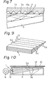
- a plurality of plates 5 having a thickness of e.g., 0.5 mm, and made of methyl methacrylate polymer are arranged in layered form in such a manner that the light emission edges 5a of the plates 5 form stairs 13.
- the plates 5 are fixed to each other by an adhesive (not shown) applied on both side edges 5c of the plates 5 or by heat fusion.
- the light emission edge 5a is perpendicular to the bottom of the plate 5 but the plane of light incidence 1 is inclined with respect to the bottom of the plate 5.
- the light emission edges 5a and the plane of light incidence 1 are mirror-finished.
- the stairs 13 are covered with the light diffusing plate 14.
- the light diffusing plate 14 is composed of trigonal prisms 15 arranged in the form of a plate.
- the light diffusing plate 14 is located in such a manner that the longitudinal direction of the prism 15 is parallel to the light emission edge 5a.
- the incident light rays parallel to the bottom of the plate 5 pass through the plate 5 and directly reach the light diffusing plate 14.
- the other incident light rays reach the light emission edge 5a while being reflected entirely within the plate 5 and are reflected by the surface 5d of the adjacent plate 5 and are then directed toward the light diffusing plate 14.
- the light rays reaching the light diffusing plate 14 undergo reflection or refraction by the prisms 15 and are then emitted from the light diffusing plate 14.
- the light rays emitted from the light emission edge 5a tend to advance in a direction along the bottom of the plate 5. Since the stairs 13 are covered with the light diffusing plate 14, however, the light rays emitted from the light emission edges 5a are diffused by the light diffusing plate 14, which makes it possible to obtain a plane illumination having a more uniform brightness.
- the light diffuser illustrated in Fig. 8 can be fabricated by arranging a plurality of plates 5 in layered form so that the light emission edges 5a form the stairs 13 and by disposing the light diffusing plate 14 in such a manner that it covers the stairs 13. Therefore, the light diffuser requires no special processing to be applied to the light transmitter 3, and it is easy to fabricate. Furthermore, in the light diffuser shown in Fig. 8, the plane of light incidence 1 is inclined with respect to the bottom of the plate 5. However, if the light diffuser is designed so that the plane of the light incidence I is perpendicular to the bottom of the plate 5 as shown by the chain line in Fig. 8, the light transmitter 3 can be made merely by arranging rectangular plates 5 in a layered form, which makes the fabrication of the light diffuser much easier.
- the plate 5 used has a reduced thickness, the illuminance of the plane illumination becomes more uniform.
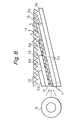
- the light diffuser shown in Fig. 10 is identical with the light diffuser shown in Fig. 8 in structure, except that the white opaque light diffusing plate 10 is further provided over the light diffusing plate 14, and the plane of light incidence 1 is covered with the flax convex cylindrical lens 12.
- the use of such a light diffuser makes it possible to eliminate the boundaries between the light emission edge 5a and the top surface 5d of the plate 5 by the white opaque light diffusing plate 10 and thereby obtain a plane illumination having a more uniform brightness.
- a polyester film having a mirror surface is desirably used as the light reflector 4.
- a vapor-deposited film of metal e.g., aluminum
- the light reflector 4 may be provided in direct contact with the light emission edges 5a. Alternatively, a space may be formed between the light emission edges 5a and the light reflector 4.
- the surface of the light reflector 4 is preferably smooth, but the surface of the light reflector 4 may be sprayed with beads of methacrylic resins.
- the light reflector 4 shown in Fig. 2 may be provided in direct contact with the edge 5a of each plate 5 and a part of the bottom thereof as illustrated in Fig. 3.
- the light reflector 4 shown in Fig. 3 may be provided so that a space is formed between the edge 5a of the plate 5 and the light reflector 4 for as illustrated in Fig. 2.
- the surface of the light reflector 4 may be roughened to scatter the light rays in order to form a reflector similar to the light scattering reflector 9 of Fig. 4.
- the light emission edges 5a of the plates 5, whether the plates 5 are composed of resin plates 5 or optical fiber sheets 5, are of usually mirror-finished. If necessary, the light emission edge 5a may be processed into a roughened surface in the form of ground glass. If the light emission edge 5a is a roughened surface, the light rays emitted from the edge 5a may be diffused to a higher degree. This permits elimination of the appearance of the boundaries between the plate 5 on the plane to be illuminated 8 and thus a plane illumination having a more uniform brightness may be obtained.
- the light transmitter 3 is composed of transparent resin plates 5, even if the distance between the plane of light incidence 1 and the light emission edge 5a is long, no substantial reduction occurs in the light quantity while the light rays are transmitted through the plates 5, with the result that a plane illumination having a uniform brightness can be obtained. If a material having a mirror surface is interposed between the plates 5 or a metallic film is formed on the surfaces of the plate 5 by, e.g., a vacuum deposition method, so as to make the surfaces mirror-smooth, it is possible to obtain a plane illuminate having a more uniform brightness.
- the efficiency of utilization of light incident on the light transmitter 3 can be increased. In this case, the processability of the light transmitter 3 also can be improved. If an adhesive is applied on the entire surface of the plates 5, the plates 5 can be then be more tightly fixed to each other.
- the angle between the plane of light incidence 1 and the light emission edge 5a, the angle between the plane of light incidence 1 and the bottom of the plate 5, and the angle between the light emission edge 5a and the bottom of the plate 5 may be optionally selected.
- the plates 5 of the light transmitter 3 are preferably made of methacrylic resins comprising a homopolymer or copolymer of methyl methacrylate, although the use of the methacrylic resins is not critical.
- methacrylic resins comprising a homopolymer or copolymer of methyl methacrylate, although the use of the methacrylic resins is not critical.
- polycarbonate resins also may be used as a material for the plate 5.
- Various types of light-transmissible materials can be used for the light diffusing plate 10.
- Methyl methacrylate copolymers containing a light diffusing agent such as titanium oxide is preferably used.
- the methyl methacrylate copolymers used are preferably those polymers obtianed by multi-stage polymerization, as disclosed in U.S. Patent Nos. 3804925, 4052525, and 4173600 and U.S. patent Application No. 526,546, filed August 26, 1983.
- the light diffusing plate 10 having a smooth surface at both sides thereof, as illustrated in Figs. 6 and 7, may be used in combination with the light diffusing plate 10 as illustrated in Fig. 6 or 8.
- the cross-sectional profile of the protrusions 10a of the light diffusing plate 10 shown in Fig. 6 and the prisms 15 of the light diffusing plate 14 shown in Fig. 8 and the spacing between these protrusions 10a or prisms 15 may be appropriately determined.
- the condensing lens 12 used is preferably a flat convex cylindrical lens, though it is not limited thereto.
- the light diffuser of the present invention may include a plurality of light transmitters 3 as illustrated in Fig. 11.
- Figures 11(a) and (b) illustrate light diffusers comprising a combination of two light transmitters 3 of the type shown in Fig. 2.
- Figures 11(c) and (d) illustrate light diffusers comprising a combination of two light transmitters 3 of the type shown in Fig. 5.
- the combination of the light transmitters 3 is not limited to the above-mentioned system.
- the light diffuser shown in Fig. 11 may also include the light diffusing plate 10.
- the light diffusing plate 10 is provided ahead of the light emission edge 5a of the light transmitter 3, it is possible to obtain a plane illumination having a more uniform illuminance.
- the condensing lens 12 since the condensing lens 12 is used a plane illumination having a high brightness is obtained.
- the distance between the light emission edge 5a and the plane to be illuminated 8 can be made larger and, therefore, it is possible to obtain a plane illumination free from the boundaries between the plates 5 on the plane to be illuminated 8 and having an extremely excellent brightness as compared with the conventional prior art.
- the light diffuser of the present invention is easy to fabricate, and thus can be commercially utilized.
- the light diffuser of the present invention can be used as a backlight for displaying signboards, display devices, plane illumination for design, liquid crystals, and the like.
- Fig. 1 Four light diffusers as shown in Fig. 1 were fabricated using sheets of 110 mm width made of a methyl methacrylate polymer having various thicknesses.
- the thicknesses of the sheet of a diffuser were 0.2 mm, 0.5 mm, 1.0 mm or 2.0 mm. These sheets were cut and laminated so that the light emission edges 5a thereof formed stairs 13. The cut surfaces of the laminate were polished so as to provide flat surfaces.
- the sheets were laminated so that Ln was 110 mm and L a as 110 mm and L 1 was 11 mm.
- a light reflector 4 was provided in contact with the light emission edges 5a.
- An aluminum-vapor-deposited polyester film having a thickness of 100 ⁇ m was used as the light reflector 4.
- All the light diffusers comprising a combination of the laminate of the above-mentioned sheets and the light reflector 4 provided a plane illumination having a uniform brightness. Also, where the above-mentioned vapor-deposited film sprayed with beads of a methacrylate polymer was used as the reflective film, a plane illumination having a uniform brightness was obtained.
- Fig. 4 Four light diffusers as shown in Fig. 4 were fabricated using sheets of 110 mm width made of a methyl methacrylate polymer having various thicknesses.
- the thickness of the sheet of a diffuser were 0.2 mm, 0.5 mm, 1.0 mm or 2.0 mm. These sheets were cut and laminated so that the light emission edges 5a thereof formed stairs 13. The edges 5a for light incidence and emission of these sheets were mirror-finished. Fixation of the laminate was carried out by heat-fusing the sides of the sheets with each other.
- An aluminum-vapor-deposited polyester film having a thickness of 100 p was used as the light reflector 4.
- a white opaque methacrylic resin plate having a thickness of 2 mm was used as the light diffusing plate 10.
- the case 11 was formed by subjecting an iron sheet of 0.2 mm thickness to sheet metal working.
- the laminate of the methacrylator polymer sheet, the light diffusing plate 10, the light reflector 4, and the case 11 were assembled as shown in Fgi. 4.
- the resultant light diffusers all provided a plane illumination having an extremely uniform brightness.
- Figure 12 illustrates the illuminance distribution of one embodiment of a light diffuser having the structure shown in Example 2.
- the light transmitter 3 of this light diffuser is made by laminating 16 methyl methacrylate polymer sheets 110 mm wide by 1 mm thick so that L 0 is 110 and L 1 is 16 mm.
- the ordinate represents the illuminance and the abscissa represents the distance from the light source.
- the solid line indicates the illuminance distribution according to this example (a 1 mm thick sheet is used), and the dotted line indicates the illuminance distribution of a light diffuser which was produced according to the same procedures as mentioned above, except that a piece of methyl methacrylate polymer sheet having a thickness of 16 mm was used in place of the light transmitter 3 of this example. It is apparent from Fig. 12 that the light diffuser of the present invention provides a uniform luminance distribution.
- Fig. 10 Four light diffusers shown in Fig. 10 were fabricated in the same manner as in Example 2. Four types of methyl methacrylate polymer sheets having thicknesses of 0.2 mm, 0.5 mm, 1.0 mm, and 2.0 mm were used as the light-transmissable plate 5.
- the first light diffusing plate 14 was provided above and adjacent to the light emission edges 5a of the plates 5.
- the light diffusing plate 14 was a transparent sheet of a methacrylic resin on one surface of which prisms 15 were formed parallel to each other at a pitch of 0.7 mm. This transparent sheet was made by extrusion.
- a white opaque methacrylic resin sheet (2 mm thick) was used as the other light diffusing plate 10.
- a semicylindrical lens having a width (L1) of incidence plane of 11 mm and made of a methacrylic resin was used as the condensing lens 12.
- the case 11 was formed by subjecting an iron sheet of 0.2 mm thickness to sheet metal working.
- the laminate of the methyl methacrylate polymer sheets 5, the light diffusing plates 14 and 10, the condensing lens 12, and the case 11 were assembled as shown in Fig. 10.
- the resultant light diffusers all provided a plane illumination having a uniform brightness.
Abstract
Description
- The present invention relates to a light diffuser most suitable for use as a plane lighting device. More particularly, the present invention relates to an edge lighting type light diffuser useful as a plane lighting device.
- Conventionally, large-sized plane lighting units are used as signboard and other various large display devices, and small-sized plane lighting units are used as display devices for various types of machinery and apparatus, and for liquid crystal watches. In signboards and large-sized display devices, a plane to be illuminated is generally illuminated by a plurality of line light sources, for example, fluorescent lighting, or point light sources, e.g., incandescent lamps, which are located behind a light diffusing plate. However, to obtain a plane illumination having a uniform brightness with such plane lighting units, the light diffusing plate and the light source must be spaced quite far apart, or a plurality of light sources must be located in close contact with each other. This requirement necessarily results in an enlargement in the size of the plane lighting unit or an increase in the number of light sources, with the results that the plane lighting unit not only becomes costly but there is also a significant increase in the power consumption.
- In an attempt to overcome these deficiencies, some plane lighting units use a single transparent light conducting plate through which light is conducted from one side, thereby obtaining plane illumination. Where such a transparent light conducting plate is used, if the incident light rays from the light source are parallel, it is possible to obtain plane illumination having a substantially uniform brightness. However, since the light from the light source is practically diffused in a radial manner, the quantity of light emitted from the transparent light conducting plate is very bright in the vicinity of the light source and relatively dark at a location remote from the light source. Thus, in the prior art, it has been difficult to obtain uniform plane illumination.
- Accordingly, one object of the present invention is to provide a novel light diffuser capable of providing uniform plane illumination which is also easy to manufacture.
- Another object of the present invention is to provide a light diffuser in the form of a plane usable for signboards, large-sized display devices, display devices for various types of machinery and apparatus, and liquid crystal devices, and the like.
- The objects of the present invention are attained by a light diffuser system which uses a plurality of light-transmitting plates in an edge lighting type light diffuser. The system utilizes a light incidence plane a light transmitting structure, and a light emission plane.
- A more complete appreciation of the invention and many of the attendant advantages thereof will be readily obtained as the same becomes better understood by reference to the following detailed description when considered in connection with the accompanying drawings, wherein:
- Figure 1 is a cross-sectional view of one embodiment of a light diffuser of the present invention;
- Fig. 2 is a cross-sectional view of another embodiment of a light diffuser of the present invention;
- Fig. 3 is a cross-sectional view of a further embodiment of a light diffuser of the present invention;
- Fig. 4 is a cross-sectional view of a further embodiment of a light diffuser of the present invention;
- Fig. 5 is a cross-sectional view of a further embodiment of a light diffuser of the present invention;
- Fig. 6 is a cross-sectional view of a further embodiment of a light diffuser of the present invention;
- Fig. 7 is a cross-sectional view illustrating the vicinity of a protrusion provided in a light diffusing plate used in the light diffuser shown in Fig. 6;
- Fig. 8 is a cross-sectional view of another embodiment of a light diffuser of the present invention;
- Fig. 9 is a perspective view of a light transmitting means used in the light diffuser shown in Fig. 8;
- Fig. 10 is a cross-sectional view of a further embodiment of a light diffuser of the present invention;
- Figs. 11A to 11D are respectively explanatory views of a further embodiment of a light diffuser of the present invention; and Fig. 12 is a graph illustrating the properties of the light diffuser of the present invention.
- Referring now to the drawings, wherein like reference numerals designate identical or corresponding parts throughout the several views, and more particularly to FIGURES 1-8 thereof,
reference numeral 1 represents a plane of incidence of light;reference numeral 2, a plane of emission of light;reference numeral 3, a light transmitter;reference numeral 4, a reflector;reference numeral 5, a transparent plate;reference numeral 6, a light source;reference numeral 7, incident light;reference numeral 8, a plane to be illuminated;reference numeral 9, a light scattering reflector;reference numeral 10, a light diffusing plate;reference numeral 11, a case;reference numeral 12, a lens;reference numeral 13, a step; andreference numeral 14, a light diffusing plate having aprism 15. - In the light diffuser shown in Fig. 1, the
light transmitter 3 includes the plane oflight incidence 1 and the plane oflight emission 2, and is composed of a laminate of a plurality of thintransparent plates 5. Thelight reflection 4 composed of, for example, an aluminum-vapor-deposited polyester film having a thickness of 100 p and a mirror surface is provided at theedges 5a of theplates 5 through which the incident light is first emitted. Thelight transmitter 3 is formed by laminating a plurality of transparent light-transmissible plates 5 composed of, for example, methyl methacrylate polymer, and by fixing the sides of the laminate by using an adhesive tape or an adhesive comprising methyl methacrylate, or through heat fusion. Thelight transmitter 3 as a whole is wedge shaped. Oneedge 5a of thetransparent plate 5 is inclined at a predetermined angle a with respect to the bottom of theplate 5. Theother edge 5b of theplate 5 on which light is incident is inclined at an angle a2 smaller than the angle a1 of theedge 5a with respect to the bottom of theplate 5. In thelight transmitter 3 shown in Fig. 1, theedge 5b of theplate 5 on which light is incident constitutes the plane oflight incidence 1, and theedge 5a of theplate 5 through which light is emitted and theedge 5b of theplate 5 are perpendicular to each other. - As shown in Fig. 1,
light rays 7 incident on the plane oflight incidence 1 from thelong light source 6, shown extending in a direction perpendicular to the drawing, such as a fluorescent light, are transmitted through theplates 5 in the direction shown by the arrow A while being reflected entirely within the plates without escaping outside the plates. Theselight rays 7 are then emitted through theedges 5a of theplates 5, and immediately thereafter, the emitted light rays are reflected by thelight reflector 4 in the direction shown by the arrow B. Thelight rays 7 passing in a straight line through theplates 5 are reflected by thelight reflector 4 in the direction shown by the arrow C. Thelight rays 7 reflected in the directions of the arrows B and C are transmitted through thelight transmitter 3 across theplates 5 and then emitted through the plane oflight emission 2. Thereafter, the emitted light rays irradiate a plane to be illuminated 8 of a liquid crystal or a display located outside the light diffuser. - The light diffuser shown in Fig. 1 has the following advantages:
- Since the
light transmitter 3 is composed of a laminate of a plurality oftransparent plates 5 inclined downwardly and thelight reflector 4 is provided at thelight emission edge 5a of theplate 5,light rays 7 incident on thelight transmitter 3 are transmitted through theplate 5 and emitted through theedges 5a, and the emitted light rays are subsequently reflected by thelight reflector 4 in the directions shown by the arrows B and C. Finally, the reflected light rays irradiate the plane to be illuminated 8. Therefore, the brightness of the plane to be illuminated 8 becomes uniform throughout that plane. - Furthermore, since the light rays emitted from the
light emission edge 5a of theplate 5 are reflected by thelight reflector 4 in the directions shown by the arrows B and c, it is possible to make the distance between thelight emission edge 5a and the plane to be illuminated 8 larger. This makes it possible to effectively prevent the boundaries between theplates 5 at thelight emission edges 5a from appearing on the plane to be illuminated 8. Therefore, it is possible to obtain a plane illumination having an extremely uniform brightness as compared with the prior art. - The light diffuser shown in Fig. 2 is different from the light diffuser shown in Fig. 1 in that the light emission plane of the
light transmitter 3 is in the form of stairs comprising a plurality ofedges 5a normal to the bottom of theplates 5. Thelight reflector 4 is provided in front of thelight emission edge 5a. - When the light diffuser shown in the embodiment Fig. 2 is used, the light rays emitted from the
light emission edges 5a are reflected by thelight reflector 4 in the directions shown by the arrows D, E, and F. Therefore, it is possible to obtain plane illumination having an extremely uniform brightness in which the appearance of the boundaries between theplates 5 on the plane to be illuminated 8 is prevented, as in the light diffuser shown in Fig. 1. In addition, in the case of the light diffuser shown in Fig. 2, thelight emission edges 5a are formed at right angles to the bottom of theplates 5. Therefore, when thelight rays 7 are incident on theedges 5a after being transmitted through theplates 5, the angle of incidence is smaller than that of the light diffuser shown in Fig. 1, which results in a substantial elimination of the reflection of theincident rays 7 by theedges 5a. Accordingly, the light diffuser shown in Fig. 2 is advantageous in that the efficiency of light-transmission is extremely high. - In the light diffuser shown in Fig. 3, the
light emission edge 5a of theplate 5 is inclined so that the angle al , between the bottom of theplates 5 and thelight emission edge 5a is larger than the angle a2 between the bottom and the plane oflight incidence 1 of theplate 5. In Fig. 3, both the angles al and a2 are des signed to be 120°. In the light diffuser shown in Fig. 3, thelight reflector 4 is brought into contact with thelight emission edges 5a, and theedges 5a are in the form of stairs. In this regard, the light diffuser of Fig. 3 is different from those of Figs. 1 and 2. - In the light diffuser shown in Fig. 4, the
light scattering reflector 9 is provided at thelight emission edges 5a. Furthermore, thelight transmitter 3 and thelight diffusing plate 10 composed of, e.g., a white opaque light transmissible material, are fixed to each other by thecase 11, which also serves as a shield against the incidence of external light. - When the light diffuser shown in Fig. 4 is used, the light rays emitted from the
light emission edges 5a are scattered and reflected by thelight scattering reflector 9, so that light rays I and J, for example, are generated.. These light rays are incident on thelight diffusing plate 10 and are then further diffused. This diffusion makes it possible to obtain a plane illumination having an extremely uniform brightness in which the boudaries between theplates 5 on the plane to be illuminated are more effectively eliminated than in the light diffusers shown in Figs. 1 to 3. In Fig. 4, the angles a1 and U2 are designed to be 130° and 100°, respectively. - In the light diffuser illustrated in Fig. 5, the flat convex
cylindrical lens 12 made of a light-transmissible material is provided at the plane oflight incidence 1 of thelight transmitter 3 fixed to thecase 11. Furthermore, thelight diffusing plate 10 is provided at thelight emission edges 5a. - The top surface of the
light transmitter 3 shown in Fig. 5 is composed of theedges 5a ofplates 5 each inclined at a predetermined angle with respect to the bottom of theplate 5. The plane oflight incidence 1 in the form of a rectangle is composed of theother edges 5b. The angle a3 between theedge 5b and the bottom of theplate 5 is larger than the angle a4 between theedge 5a and the bottom of theplate 5. Both theedges plates 5 to thelight emission edges 5a. In this light diffuser, theedge 5a and theedge 5b are perpendicular to each other, and thus the plane oflight incidence 1 and the plane oflight emission 2 are also perpendicular to each other. - In the light diffuser shown in Fig. 5,
light rays 7 incident on the plane oflight incidence 1 from thelong light source 6, such as a fluorescent light, through the flat convexcylindrical lens 12 form condensed light rays 17 which are transmitted through theplates 5 in the direction shown by the arrow A while thelight rays 7 are reflected entirely within the plates without escaping outside the plates. Thereafter, the light rays are emitted through thelight emission edges 5a and are then diffused by thelight diffusing plate 10. - The light diffuser shown in Fig. 5 has the following advantages.
- Since the
light diffusing plate 10 made of a white opaque light-transmissible material is provided at thelight emission edges 5a, the light rays emitted from theedges 5a are diffused by thislight diffusing plate 10. This permits elimination of the boundaries between theplates 5 on the plane to be illuminated. Therefore, it is possible to obtain plane illumination having an extremely uniform brightness on the plane to be illuminated. Furthermore, since the flat convexcylindrical lens 12 is provided at the plane oflight incidence 1 of thelight transmitter 3,light rays 7 radiated from thelight source 6 are condensed to form light rays by thislens 12, which results in an increase in the quantity of light incident of theplates 5 and thus an increased efficiency of use of thelight rays 7 from thelight source 6. In the light diffusers illustrated in Figs. 6 and 7, alight diffusing plate 10 made of transparent methacrylic resin is used in place of thelight diffusing plate 10 of Fig. 5. Thislight diffusing plate 10 is formed by extrusion. On one surface of thelight diffusing plate 10, a plurality ofprotrusions 10a are provided having a triangular cross-sectional profile and extending at right angles to a direction along which theplates 5 are arranged (in a direction perpendicular to the drawing) and are equidistant from each other. - Since the light diffuser shown in Fig. 6 includes the unique
light diffusing plate 10 as mentioned above, it has the following advantages in addition to the advantages possessed by the light diffuser shown in Fig. 5. - The light rays, emitted from the
light emission edges 5a, which are directed mainly along the central axis of an optical fiber (not shown) at the time of emission, are diffused by theprotrusions 10a of thelight diffusing plate 10 in a direction perpendicular to thelight emission edges 5a. When the light rays emitted in various directions from thelight emission edges 5a, after being transmitted through theplates 5, are incident on thelight diffusing plate 10, light rays K and L are generated due to the prism and reflection effects of theprotrusions 10a, as shown in Fig. 7. Thus, the light rays emitted from thelight emission edges 5a can be effectively diffused in a direction perpendicular to thelight emission edges 5a. This enables the brightness of the plane to be illuminated to be more uniform. - In the light diffusers illustrated in Figs. 8 and 9, a plurality of
plates 5 having a thickness of e.g., 0.5 mm, and made of methyl methacrylate polymer are arranged in layered form in such a manner that thelight emission edges 5a of theplates 5form stairs 13. Theplates 5 are fixed to each other by an adhesive (not shown) applied on both side edges 5c of theplates 5 or by heat fusion. Thelight emission edge 5a is perpendicular to the bottom of theplate 5 but the plane oflight incidence 1 is inclined with respect to the bottom of theplate 5. Preferably, thelight emission edges 5a and the plane oflight incidence 1 are mirror-finished. Thestairs 13 are covered with thelight diffusing plate 14. Thelight diffusing plate 14 is composed oftrigonal prisms 15 arranged in the form of a plate. Thelight diffusing plate 14 is located in such a manner that the longitudinal direction of theprism 15 is parallel to thelight emission edge 5a. - In the light diffuser illustrated in Fig. 8, the incident light rays parallel to the bottom of the
plate 5 pass through theplate 5 and directly reach thelight diffusing plate 14. The other incident light rays reach thelight emission edge 5a while being reflected entirely within theplate 5 and are reflected by thesurface 5d of theadjacent plate 5 and are then directed toward thelight diffusing plate 14. - The light rays reaching the
light diffusing plate 14 undergo reflection or refraction by theprisms 15 and are then emitted from thelight diffusing plate 14. - In the case of the light diffuser shown in Fig. 8, when light rays are incident on the plane of
incident light 1 in an equal quantity for eachplate 5, the quantities of the light emitted from eachlight emission edge 5a located at a different distance from theincidence plane 1 are substantially equal to each other, with the result that plane illumination having a uniform illuminance can be obtained. If thestairs 13 are arranged at a constant pitch, the quantities of light reaching the portion corresponding to each of thestairs 13 are equal to each other, whereby plane illumination having a more uniform illuminance can be obtained. - Also, in the light diffuser shown in Fig. 8, the light rays emitted from the
light emission edge 5a tend to advance in a direction along the bottom of theplate 5. Since thestairs 13 are covered with thelight diffusing plate 14, however, the light rays emitted from thelight emission edges 5a are diffused by thelight diffusing plate 14, which makes it possible to obtain a plane illumination having a more uniform brightness. - The light diffuser illustrated in Fig. 8 can be fabricated by arranging a plurality of
plates 5 in layered form so that thelight emission edges 5a form thestairs 13 and by disposing thelight diffusing plate 14 in such a manner that it covers thestairs 13. Therefore, the light diffuser requires no special processing to be applied to thelight transmitter 3, and it is easy to fabricate. Furthermore, in the light diffuser shown in Fig. 8, the plane oflight incidence 1 is inclined with respect to the bottom of theplate 5. However, if the light diffuser is designed so that the plane of the light incidence I is perpendicular to the bottom of theplate 5 as shown by the chain line in Fig. 8, thelight transmitter 3 can be made merely by arrangingrectangular plates 5 in a layered form, which makes the fabrication of the light diffuser much easier. - In addition, if the
plate 5 used has a reduced thickness, the illuminance of the plane illumination becomes more uniform. - The light diffuser shown in Fig. 10 is identical with the light diffuser shown in Fig. 8 in structure, except that the white opaque
light diffusing plate 10 is further provided over thelight diffusing plate 14, and the plane oflight incidence 1 is covered with the flax convexcylindrical lens 12. The use of such a light diffuser makes it possible to eliminate the boundaries between thelight emission edge 5a and thetop surface 5d of theplate 5 by the white opaquelight diffusing plate 10 and thereby obtain a plane illumination having a more uniform brightness. - A polyester film having a mirror surface is desirably used as the
light reflector 4. If necessary, a vapor-deposited film of metal, e.g., aluminum, may be used. Thelight reflector 4 may be provided in direct contact with thelight emission edges 5a. Alternatively, a space may be formed between thelight emission edges 5a and thelight reflector 4. The surface of thelight reflector 4 is preferably smooth, but the surface of thelight reflector 4 may be sprayed with beads of methacrylic resins. - For example, the
light reflector 4 shown in Fig. 2 may be provided in direct contact with theedge 5a of eachplate 5 and a part of the bottom thereof as illustrated in Fig. 3. Similarly, thelight reflector 4 shown in Fig. 3 may be provided so that a space is formed between theedge 5a of theplate 5 and thelight reflector 4 for as illustrated in Fig. 2. - The surface of the
light reflector 4 may be roughened to scatter the light rays in order to form a reflector similar to thelight scattering reflector 9 of Fig. 4. - The
light emission edges 5a of theplates 5, whether theplates 5 are composed ofresin plates 5 oroptical fiber sheets 5, are of usually mirror-finished. If necessary, thelight emission edge 5a may be processed into a roughened surface in the form of ground glass. If thelight emission edge 5a is a roughened surface, the light rays emitted from theedge 5a may be diffused to a higher degree. This permits elimination of the appearance of the boundaries between theplate 5 on the plane to be illuminated 8 and thus a plane illumination having a more uniform brightness may be obtained. - Since the
light transmitter 3 is composed oftransparent resin plates 5, even if the distance between the plane oflight incidence 1 and thelight emission edge 5a is long, no substantial reduction occurs in the light quantity while the light rays are transmitted through theplates 5, with the result that a plane illumination having a uniform brightness can be obtained. If a material having a mirror surface is interposed between theplates 5 or a metallic film is formed on the surfaces of theplate 5 by, e.g., a vacuum deposition method, so as to make the surfaces mirror-smooth, it is possible to obtain a plane illuminate having a more uniform brightness. - Similarly, if a layer made of a material having a low refractive index, such as water, adhesives and oligomers, is interposed between the
plate 5, the efficiency of utilization of light incident on thelight transmitter 3 can be increased. In this case, the processability of thelight transmitter 3 also can be improved. If an adhesive is applied on the entire surface of theplates 5, theplates 5 can be then be more tightly fixed to each other. - The angle between the plane of
light incidence 1 and thelight emission edge 5a, the angle between the plane oflight incidence 1 and the bottom of theplate 5, and the angle between thelight emission edge 5a and the bottom of theplate 5 may be optionally selected. - The
plates 5 of thelight transmitter 3 are preferably made of methacrylic resins comprising a homopolymer or copolymer of methyl methacrylate, although the use of the methacrylic resins is not critical. For example, polycarbonate resins also may be used as a material for theplate 5. - Various types of light-transmissible materials can be used for the
light diffusing plate 10. Methyl methacrylate copolymers containing a light diffusing agent such as titanium oxide is preferably used. The methyl methacrylate copolymers used are preferably those polymers obtianed by multi-stage polymerization, as disclosed in U.S. Patent Nos. 3804925, 4052525, and 4173600 and U.S. patent Application No. 526,546, filed August 26, 1983. - The
light diffusing plate 10 having a smooth surface at both sides thereof, as illustrated in Figs. 6 and 7, may be used in combination with thelight diffusing plate 10 as illustrated in Fig. 6 or 8. The cross-sectional profile of theprotrusions 10a of thelight diffusing plate 10 shown in Fig. 6 and theprisms 15 of thelight diffusing plate 14 shown in Fig. 8 and the spacing between theseprotrusions 10a orprisms 15 may be appropriately determined. - The condensing
lens 12 used is preferably a flat convex cylindrical lens, though it is not limited thereto. - The light diffuser of the present invention may include a plurality of
light transmitters 3 as illustrated in Fig. 11. Figures 11(a) and (b) illustrate light diffusers comprising a combination of twolight transmitters 3 of the type shown in Fig. 2. Figures 11(c) and (d) illustrate light diffusers comprising a combination of twolight transmitters 3 of the type shown in Fig. 5. The combination of thelight transmitters 3 is not limited to the above-mentioned system. The light diffuser shown in Fig. 11 may also include thelight diffusing plate 10. - In accordance with the light diffuser of the present invention, since light rays are transmitted from the plane of
light incidence 1 to thelight emission edge 5a through thelight transmitter 3, it is possible to obtain a plane illumination having a more uniform illuminance. - In accordance with one embodiment of the light diffuse of the present invention, since the
light diffusing plate 10 is provided ahead of thelight emission edge 5a of thelight transmitter 3, it is possible to obtain a plane illumination having a more uniform illuminance. - In accordance with another embodiment of the light diffuser of the present invention, since the condensing
lens 12 is used a plane illumination having a high brightness is obtained. - In accordance with one mode of the light diffuser of the present invention, since the
light reflector 4 is provided at thelight emission edge 5a, the distance between thelight emission edge 5a and the plane to be illuminated 8 can be made larger and, therefore, it is possible to obtain a plane illumination free from the boundaries between theplates 5 on the plane to be illuminated 8 and having an extremely excellent brightness as compared with the conventional prior art. - Furthermore, the light diffuser of the present invention is easy to fabricate, and thus can be commercially utilized.
- The light diffuser of the present invention can be used as a backlight for displaying signboards, display devices, plane illumination for design, liquid crystals, and the like.
- The following examples illustrate the specifics of the formation and the test results of some of the actually constructed samples formed in accordance with the present invention.
- Four light diffusers as shown in Fig. 1 were fabricated using sheets of 110 mm width made of a methyl methacrylate polymer having various thicknesses. The thicknesses of the sheet of a diffuser were 0.2 mm, 0.5 mm, 1.0 mm or 2.0 mm. These sheets were cut and laminated so that the
light emission edges 5a thereof formedstairs 13. The cut surfaces of the laminate were polished so as to provide flat surfaces. In Fig. 1, the sheets were laminated so that Ln was 110 mm and La as 110 mm and L1 was 11 mm. - A
light reflector 4 was provided in contact with thelight emission edges 5a. An aluminum-vapor-deposited polyester film having a thickness of 100 µm was used as thelight reflector 4. - All the light diffusers comprising a combination of the laminate of the above-mentioned sheets and the
light reflector 4 provided a plane illumination having a uniform brightness. Also, where the above-mentioned vapor-deposited film sprayed with beads of a methacrylate polymer was used as the reflective film, a plane illumination having a uniform brightness was obtained. - Four light diffusers as shown in Fig. 4 were fabricated using sheets of 110 mm width made of a methyl methacrylate polymer having various thicknesses. The thickness of the sheet of a diffuser were 0.2 mm, 0.5 mm, 1.0 mm or 2.0 mm. These sheets were cut and laminated so that the
light emission edges 5a thereof formedstairs 13. Theedges 5a for light incidence and emission of these sheets were mirror-finished. Fixation of the laminate was carried out by heat-fusing the sides of the sheets with each other. - An aluminum-vapor-deposited polyester film having a thickness of 100 p was used as the
light reflector 4. - On the other hand, a white opaque methacrylic resin plate having a thickness of 2 mm was used as the
light diffusing plate 10. - The
case 11 was formed by subjecting an iron sheet of 0.2 mm thickness to sheet metal working. - The laminate of the methacrylator polymer sheet, the
light diffusing plate 10, thelight reflector 4, and thecase 11 were assembled as shown in Fgi. 4. The resultant light diffusers all provided a plane illumination having an extremely uniform brightness. - Figure 12 illustrates the illuminance distribution of one embodiment of a light diffuser having the structure shown in Example 2. The
light transmitter 3 of this light diffuser is made by laminating 16 methyl methacrylate polymer sheets 110 mm wide by 1 mm thick so that L0 is 110 and L1 is 16 mm. In Fig. 12, the ordinate represents the illuminance and the abscissa represents the distance from the light source. The solid line indicates the illuminance distribution according to this example (a 1 mm thick sheet is used), and the dotted line indicates the illuminance distribution of a light diffuser which was produced according to the same procedures as mentioned above, except that a piece of methyl methacrylate polymer sheet having a thickness of 16 mm was used in place of thelight transmitter 3 of this example. It is apparent from Fig. 12 that the light diffuser of the present invention provides a uniform luminance distribution. - Four light diffusers shown in Fig. 10 were fabricated in the same manner as in Example 2. Four types of methyl methacrylate polymer sheets having thicknesses of 0.2 mm, 0.5 mm, 1.0 mm, and 2.0 mm were used as the light-
transmissable plate 5. - The first
light diffusing plate 14 was provided above and adjacent to thelight emission edges 5a of theplates 5. Thelight diffusing plate 14 was a transparent sheet of a methacrylic resin on one surface of which prisms 15 were formed parallel to each other at a pitch of 0.7 mm. This transparent sheet was made by extrusion. - A white opaque methacrylic resin sheet (2 mm thick) was used as the other
light diffusing plate 10. - A semicylindrical lens having a width (L1) of incidence plane of 11 mm and made of a methacrylic resin was used as the condensing
lens 12. - The
case 11 was formed by subjecting an iron sheet of 0.2 mm thickness to sheet metal working. - The laminate of the methyl
methacrylate polymer sheets 5, thelight diffusing plates lens 12, and thecase 11 were assembled as shown in Fig. 10. The resultant light diffusers all provided a plane illumination having a uniform brightness. - Obviously, numerous modifications and variations of the present invention are possible in light of the above teachings. It is therefore to be understood that within the scope of the appended claims, the invention may be practiced otherwise than as specifically described herein.
Claims (29)
Applications Claiming Priority (4)
| Application Number | Priority Date | Filing Date | Title |
|---|---|---|---|
| JP59136691A JPS6115104A (en) | 1984-07-02 | 1984-07-02 | Optical diffuser |
| JP136691/84 | 1984-07-02 | ||
| JP227537/84 | 1984-10-29 | ||
| JP59227537A JPS61105504A (en) | 1984-10-29 | 1984-10-29 | Optical diffuser |
Publications (2)
| Publication Number | Publication Date |
|---|---|
| EP0167721A1 true EP0167721A1 (en) | 1986-01-15 |
| EP0167721B1 EP0167721B1 (en) | 1989-10-11 |
Family
ID=26470197
Family Applications (1)
| Application Number | Title | Priority Date | Filing Date |
|---|---|---|---|
| EP85104401A Expired EP0167721B1 (en) | 1984-07-02 | 1985-04-11 | Light diffuser |
Country Status (4)
| Country | Link |
|---|---|
| US (1) | US4642736A (en) |
| EP (1) | EP0167721B1 (en) |
| KR (1) | KR910001084B1 (en) |
| DE (1) | DE3573649D1 (en) |
Cited By (24)
| Publication number | Priority date | Publication date | Assignee | Title |
|---|---|---|---|---|
| EP0242308A1 (en) * | 1986-04-18 | 1987-10-21 | Pierre Alexandre Blanchet | Luminous display device |
| EP0290266A2 (en) * | 1987-05-08 | 1988-11-09 | Minnesota Mining And Manufacturing Company | Elevated back-lit display |
| EP0317250A2 (en) * | 1987-11-12 | 1989-05-24 | Mitsubishi Rayon Co., Ltd. | Plane light source unit |
| EP0392863A2 (en) * | 1989-04-13 | 1990-10-17 | Fujitsu Limited | Backlight |
| EP0402146A2 (en) * | 1989-06-08 | 1990-12-12 | General Electric Company | Prismatic illuminator for flat panel display |
| DE3941653A1 (en) * | 1989-12-16 | 1991-06-20 | Teldix Gmbh | Map reading aid incorporating notch in transparent wedge - with roughening or matt finish to facets through which light enters from lamp at broad end |
| EP0438768A1 (en) * | 1990-01-26 | 1991-07-31 | marketing-displays Produktionsgesellschaft für Werbe- und Verkaufsförderungssysteme mbH | Luminous display device |
| EP0450115A1 (en) * | 1988-05-05 | 1991-10-09 | Minnesota Mining And Manufacturing Company | Illuminating device having non-absorptive variable transmissivity cover |
| EP0496323A2 (en) * | 1991-01-22 | 1992-07-29 | Toray Industries, Inc. | Reflector for a surface light source |
| EP0515723A1 (en) * | 1990-01-26 | 1992-12-02 | Dimension Technologies, Inc. | Illumination for transmissive displays |
| NL9201110A (en) * | 1991-06-24 | 1993-01-18 | Mitsubishi Electric Corp | LIGHTING UNIT WITH LUMINOUS SURFACE. |
| EP0545429A2 (en) * | 1991-12-06 | 1993-06-09 | Canon Kabushiki Kaisha | Surface lighting device and a display having such a lighting device |
| US5243506A (en) * | 1991-06-17 | 1993-09-07 | Tir Systems Ltd. | High aspect ratio light emitter having high uniformity and directionality |
| US5339382A (en) * | 1993-02-23 | 1994-08-16 | Minnesota Mining And Manufacturing Company | Prism light guide luminaire with efficient directional output |
| WO1997001726A1 (en) * | 1995-06-26 | 1997-01-16 | Minnesota Mining And Manufacturing Company | Backlight system with multilayer optical film reflector |
| US5661839A (en) * | 1996-03-22 | 1997-08-26 | The University Of British Columbia | Light guide employing multilayer optical film |
| EP0814300A1 (en) * | 1996-06-21 | 1997-12-29 | Casio Computer Company Limited | Surface light source device and liquid crystal display device using the same |
| EP1089034A1 (en) * | 1999-09-30 | 2001-04-04 | Valeo Vision | Lighting module comprising a light pipe for motor vehicle |
| FR2799265A1 (en) * | 1999-09-30 | 2001-04-06 | Valeo Vision | Motor vehicle head lamp module has transparent plates joined together by 3 - 5 mm spots of adhesive at intervals. |
| US6224223B1 (en) | 1997-12-22 | 2001-05-01 | Casio Computer Co., Ltd. | Illumination panel and display device using the same |
| US6356391B1 (en) | 1999-10-08 | 2002-03-12 | 3M Innovative Properties Company | Optical film with variable angle prisms |
| US6447135B1 (en) | 1999-10-08 | 2002-09-10 | 3M Innovative Properties Company | Lightguide having a directly secured reflector and method of making the same |
| US6845212B2 (en) | 1999-10-08 | 2005-01-18 | 3M Innovative Properties Company | Optical element having programmed optical structures |
| US7046905B1 (en) | 1999-10-08 | 2006-05-16 | 3M Innovative Properties Company | Blacklight with structured surfaces |
Families Citing this family (55)
| Publication number | Priority date | Publication date | Assignee | Title |
|---|---|---|---|---|
| US4766524A (en) * | 1986-02-07 | 1988-08-23 | Hitachi, Ltd. | Back light device for uniformly illuminating a liquid crystal display plate |
| US4822145A (en) * | 1986-05-14 | 1989-04-18 | Massachusetts Institute Of Technology | Method and apparatus utilizing waveguide and polarized light for display of dynamic images |
| US4729067A (en) * | 1986-09-26 | 1988-03-01 | Mitsubishi Rayon Company Ltd. | Light diffusing device |
| DK21487D0 (en) * | 1987-01-15 | 1987-01-15 | Nils Toft | PLATFORM LIGHT |
| US5046826A (en) * | 1987-09-19 | 1991-09-10 | Canon Kabushiki Kaisha | Illuminator and display panel employing the illuminator |
| US4792884A (en) * | 1987-10-19 | 1988-12-20 | Prince Corporation | Illuminated vanity mirror visor |
| JPH01107406A (en) * | 1987-10-20 | 1989-04-25 | Chatani Sangyo Kk | Surface lighting apparatus |
| US4989933A (en) * | 1989-04-24 | 1991-02-05 | Duguay Michel A | Guided light diffuser |
| US5193899A (en) * | 1989-04-25 | 1993-03-16 | Mitsubishi Rayon Co., Ltd. | Planar light-source device and illumination apparatus using the same |
| US5099343A (en) * | 1989-05-25 | 1992-03-24 | Hughes Aircraft Company | Edge-illuminated liquid crystal display devices |
| US5022740A (en) * | 1990-01-04 | 1991-06-11 | Steve Forthner | Instrument gauge light projection device |
| US5057974A (en) * | 1990-06-22 | 1991-10-15 | Tatsuji Mizobe | System for uniformly illuminating liquid crystal display board from rear side |
| US5207498A (en) * | 1991-08-27 | 1993-05-04 | Electrolux Corporation | Vacuum cleaner headlight |
| US5769522A (en) * | 1991-09-09 | 1998-06-23 | Enplas Corporation | Surface light source device |
| US5414599A (en) * | 1991-09-09 | 1995-05-09 | Enplas Corporation | Surface light source device |
| US5211463A (en) * | 1992-03-11 | 1993-05-18 | Kaiser Aerospace & Electronics Corporation | Backlight for liquid crystal devices |
| DE4209505C1 (en) * | 1992-03-24 | 1993-07-08 | O & K Orenstein & Koppel Ag, 1000 Berlin, De | Safe lighting system for indoor and outdoor escalators - employs optical fibre assembly and single light-source to illuminate escalator steps without need for electrical wiring and weatherseals |
| JP3136200B2 (en) * | 1992-07-22 | 2001-02-19 | 株式会社日立製作所 | Liquid crystal display |
| US5497294A (en) * | 1992-08-07 | 1996-03-05 | Minnesota Mining And Manufacturing Company | Conspicuity enhancer |
| US5432876C1 (en) * | 1992-10-19 | 2002-05-21 | Minnesota Mining & Mfg | Illumination devices and optical fibres for use therein |
| US5899552A (en) * | 1993-11-11 | 1999-05-04 | Enplas Corporation | Surface light source device |
| DE69435174D1 (en) | 1993-12-21 | 2009-01-15 | Minnesota Mining & Mfg | Multilayer optical film |
| US6025897A (en) | 1993-12-21 | 2000-02-15 | 3M Innovative Properties Co. | Display with reflective polarizer and randomizing cavity |
| US5659643A (en) * | 1995-01-23 | 1997-08-19 | Minnesota Mining And Manufacturing Company | Notched fiber array illumination device |
| JP3682313B2 (en) * | 1995-03-08 | 2005-08-10 | 日東樹脂工業株式会社 | Surface light source device and liquid crystal display |
| AU695608B2 (en) * | 1995-06-07 | 1998-08-20 | Toyoda Gosei Co. Ltd. | Light-driven display device |
| US5631994A (en) * | 1995-08-23 | 1997-05-20 | Minnesota Mining And Manufacturing Company | Structured surface light extraction overlay and illumination system |
| US5905826A (en) * | 1996-01-24 | 1999-05-18 | Minnesota Mining And Manufacturing Co. | Conspicuity marking system including light guide and retroreflective structure |
| US5721630A (en) * | 1996-03-12 | 1998-02-24 | Polaroid Corporation | High-efficiency reflective holographic diffuser and method for making thereof |
| US5890796A (en) * | 1997-01-16 | 1999-04-06 | Ford Global Technologies, Inc. | Laser illuminated lighting system utilizing a diffractive optical element |
| US5796499A (en) * | 1997-02-28 | 1998-08-18 | Polaroid Corporation | Transmission holographic diffuser made and used to effect lateral color constancy in rear screen projection display systems |
| US5999281A (en) * | 1997-02-28 | 1999-12-07 | Polaroid Corporation | Holographic projection screen combining an elliptical holographic diffuser and a cylindrical light-collimator |
| CA2257957A1 (en) * | 1997-04-07 | 1998-10-15 | Koninklijke Philips Electronics N.V. | Luminaire |
| US6031958A (en) | 1997-05-21 | 2000-02-29 | Mcgaffigan; Thomas H. | Optical light pipes with laser light appearance |
| US6036340A (en) * | 1998-03-03 | 2000-03-14 | Ford Global Technologies, Inc. | Dimpled manifold optical element for a vehicle lighting system |
| JPH11259007A (en) * | 1998-03-10 | 1999-09-24 | Sony Corp | Reflection type display device |
| US6366270B1 (en) | 1998-05-29 | 2002-04-02 | Silicon Graphics, Inc. | Multiple light source color balancing system within a liquid crystal flat panel display |
| DE19853956B4 (en) * | 1998-08-24 | 2012-03-29 | Zumtobel Staff Ges.M.B.H. | Lighting arrangement with a light guide for room lighting |
| KR100277040B1 (en) * | 1998-10-22 | 2001-01-15 | 정기선 | Lighting sign device |
| US6827456B2 (en) * | 1999-02-23 | 2004-12-07 | Solid State Opto Limited | Transreflectors, transreflector systems and displays and methods of making transreflectors |
| US6317545B1 (en) * | 1999-09-01 | 2001-11-13 | James T. Veligdan | Stepped inlet optical panel |
| DE10042651C2 (en) * | 2000-05-08 | 2002-10-02 | Poellet Wilfried | Workplace lighting |
| GB0101682D0 (en) * | 2001-01-23 | 2001-03-07 | Cambridge 3D Display Ltd | Flat panel correction optics |
| US6989873B2 (en) * | 2003-03-19 | 2006-01-24 | Toppoly Optoelectronics Corp. | Backlight module and liquid crystal display formed therefrom |
| US6814456B1 (en) * | 2003-05-15 | 2004-11-09 | Toppoly Optoelectronics Corp. | Back light module |
| TW594258B (en) * | 2003-05-28 | 2004-06-21 | Au Optronics Corp | Back light unit |
| US7226195B2 (en) * | 2004-07-23 | 2007-06-05 | Thomas & Betts International | Cold-cathode fluorescent lamp assembly for lighting applications |
| TW200720589A (en) * | 2005-09-19 | 2007-06-01 | Koninkl Philips Electronics Nv | Luminaire with stack of flat panel light guides |
| US8462292B2 (en) * | 2008-07-31 | 2013-06-11 | Rambus Delaware Llc | Optically transmissive substrates and light emitting assemblies and methods of making same, and methods of displaying images using the optically transmissive substrates and light emitting assemblies |
| CN102246219B (en) * | 2008-12-09 | 2015-02-25 | 皇家飞利浦电子股份有限公司 | Lighting system with fiber diffusing element |
| US8724942B2 (en) | 2011-04-26 | 2014-05-13 | Corning Incorporated | Light-coupling optical systems and methods employing light-diffusing optical fiber |
| US8787717B2 (en) | 2011-04-26 | 2014-07-22 | Corning Incorporated | Systems and methods for coupling light into a transparent sheet |
| TW201305487A (en) | 2011-07-13 | 2013-02-01 | Rambus Inc | Lighting assembly with controlled configurable light redirection |
| US8956038B2 (en) * | 2012-02-22 | 2015-02-17 | Empire Technology Development Llc | Lighting device having a light guide structure |
| US9296146B1 (en) | 2012-03-09 | 2016-03-29 | Rambus Delaware Llc | Extrusion-to-sheet production line and method |
Citations (4)
| Publication number | Priority date | Publication date | Assignee | Title |
|---|---|---|---|---|
| FR746652A (en) * | 1932-06-11 | 1933-06-02 | Ditmar Geb Bruenner Ag | Light panel |
| US2347665A (en) * | 1941-03-04 | 1944-05-02 | Christensen Geneva Bandy | Internal reflection lighting means |
| US3384986A (en) * | 1966-07-25 | 1968-05-28 | James F. Davis | Progressively illuminated sign |
| GB1130601A (en) * | 1965-04-30 | 1968-10-16 | Calorific Appliances Ltd | Illuminated display apparatus |
Family Cites Families (5)
| Publication number | Priority date | Publication date | Assignee | Title |
|---|---|---|---|---|
| US2247969A (en) * | 1937-12-31 | 1941-07-01 | Adlake Co | Edge glow lighting system |
| US2480178A (en) * | 1946-05-08 | 1949-08-30 | Ivan H Zinberg | Light conductor |
| US3242328A (en) * | 1962-03-12 | 1966-03-22 | Scm Corp | Illumination device |
| CH475508A (en) * | 1967-06-28 | 1969-07-15 | Werding Winfried | Lighting device |
| US3752974A (en) * | 1971-12-13 | 1973-08-14 | Coastal Dynamics Corp | Uniform illumination with edge lighting |
-
1985
- 1985-04-11 EP EP85104401A patent/EP0167721B1/en not_active Expired
- 1985-04-11 DE DE8585104401T patent/DE3573649D1/en not_active Expired
- 1985-04-13 KR KR1019850002482A patent/KR910001084B1/en not_active IP Right Cessation
- 1985-04-17 US US06/724,275 patent/US4642736A/en not_active Expired - Fee Related
Patent Citations (4)
| Publication number | Priority date | Publication date | Assignee | Title |
|---|---|---|---|---|
| FR746652A (en) * | 1932-06-11 | 1933-06-02 | Ditmar Geb Bruenner Ag | Light panel |
| US2347665A (en) * | 1941-03-04 | 1944-05-02 | Christensen Geneva Bandy | Internal reflection lighting means |
| GB1130601A (en) * | 1965-04-30 | 1968-10-16 | Calorific Appliances Ltd | Illuminated display apparatus |
| US3384986A (en) * | 1966-07-25 | 1968-05-28 | James F. Davis | Progressively illuminated sign |
Cited By (46)
| Publication number | Priority date | Publication date | Assignee | Title |
|---|---|---|---|---|
| EP0242308A1 (en) * | 1986-04-18 | 1987-10-21 | Pierre Alexandre Blanchet | Luminous display device |
| EP0290266A3 (en) * | 1987-05-08 | 1990-08-01 | Minnesota Mining And Manufacturing Company | Elevated back-lit display |
| EP0290266A2 (en) * | 1987-05-08 | 1988-11-09 | Minnesota Mining And Manufacturing Company | Elevated back-lit display |
| US5126882A (en) * | 1987-11-12 | 1992-06-30 | Mitsubishi Rayon Co., Ltd. | Plane light source unit |
| EP0317250A3 (en) * | 1987-11-12 | 1990-03-28 | Mitsubishi Rayon Co., Ltd. | Plane light source unit |
| USRE38243E1 (en) | 1987-11-12 | 2003-09-02 | Mitsubishi Rayon Co., Ltd. | Plane light source unit |
| EP0317250A2 (en) * | 1987-11-12 | 1989-05-24 | Mitsubishi Rayon Co., Ltd. | Plane light source unit |
| USRE35704E (en) * | 1987-11-12 | 1997-12-30 | Mitsubishi Rayon Co., Ltd. | Plane light source unit |
| EP0691508A3 (en) * | 1988-05-05 | 1996-09-11 | Minnesota Mining & Mfg | Illuminating device having non-absorptive variable transmissivity cover |
| EP0450115A1 (en) * | 1988-05-05 | 1991-10-09 | Minnesota Mining And Manufacturing Company | Illuminating device having non-absorptive variable transmissivity cover |
| EP0392863A2 (en) * | 1989-04-13 | 1990-10-17 | Fujitsu Limited | Backlight |
| EP0392863A3 (en) * | 1989-04-13 | 1991-07-10 | Fujitsu Limited | Backlight |
| EP0402146A2 (en) * | 1989-06-08 | 1990-12-12 | General Electric Company | Prismatic illuminator for flat panel display |
| EP0402146A3 (en) * | 1989-06-08 | 1991-03-06 | General Electric Company | Prismatic illuminator for flat panel display |
| EP0987672A1 (en) * | 1989-06-08 | 2000-03-22 | General Electric Company | Prismatic illuminator for flat panel display |
| DE3941653A1 (en) * | 1989-12-16 | 1991-06-20 | Teldix Gmbh | Map reading aid incorporating notch in transparent wedge - with roughening or matt finish to facets through which light enters from lamp at broad end |
| EP0438768A1 (en) * | 1990-01-26 | 1991-07-31 | marketing-displays Produktionsgesellschaft für Werbe- und Verkaufsförderungssysteme mbH | Luminous display device |
| EP0515723A1 (en) * | 1990-01-26 | 1992-12-02 | Dimension Technologies, Inc. | Illumination for transmissive displays |
| EP0496323A3 (en) * | 1991-01-22 | 1993-02-10 | Toray Industries, Inc. | Reflector for a surface light source |
| EP0496323A2 (en) * | 1991-01-22 | 1992-07-29 | Toray Industries, Inc. | Reflector for a surface light source |
| US5243506A (en) * | 1991-06-17 | 1993-09-07 | Tir Systems Ltd. | High aspect ratio light emitter having high uniformity and directionality |
| NL9201110A (en) * | 1991-06-24 | 1993-01-18 | Mitsubishi Electric Corp | LIGHTING UNIT WITH LUMINOUS SURFACE. |
| US5359503A (en) * | 1991-06-24 | 1994-10-25 | Mitsubishi Denki Kabushiki Kaisha | Surface luminous lighting unit |
| US5438484A (en) * | 1991-12-06 | 1995-08-01 | Canon Kabushiki Kaisha | Surface lighting device and a display having such a lighting device |
| US5664873A (en) * | 1991-12-06 | 1997-09-09 | Canon Kabushiki Kaisha | Surface lighting device and a display having such a lighting device |
| EP0545429A3 (en) * | 1991-12-06 | 1993-10-27 | Canon Kk | Surface lighting device and a display having such a lighting device |
| EP0545429A2 (en) * | 1991-12-06 | 1993-06-09 | Canon Kabushiki Kaisha | Surface lighting device and a display having such a lighting device |
| US5339382A (en) * | 1993-02-23 | 1994-08-16 | Minnesota Mining And Manufacturing Company | Prism light guide luminaire with efficient directional output |
| WO1997001726A1 (en) * | 1995-06-26 | 1997-01-16 | Minnesota Mining And Manufacturing Company | Backlight system with multilayer optical film reflector |
| AU716525B2 (en) * | 1995-06-26 | 2000-02-24 | Minnesota Mining And Manufacturing Company | Backlight system with multilayer optical film reflector |
| US5661839A (en) * | 1996-03-22 | 1997-08-26 | The University Of British Columbia | Light guide employing multilayer optical film |
| USRE37594E1 (en) | 1996-03-22 | 2002-03-19 | The University Of British Columbia | Light guide employing multilayer optical film |
| EP0814300A1 (en) * | 1996-06-21 | 1997-12-29 | Casio Computer Company Limited | Surface light source device and liquid crystal display device using the same |
| US5914760A (en) * | 1996-06-21 | 1999-06-22 | Casio Computer Co., Ltd. | Surface light source device and liquid crystal display device using the same |
| US6224223B1 (en) | 1997-12-22 | 2001-05-01 | Casio Computer Co., Ltd. | Illumination panel and display device using the same |
| FR2799265A1 (en) * | 1999-09-30 | 2001-04-06 | Valeo Vision | Motor vehicle head lamp module has transparent plates joined together by 3 - 5 mm spots of adhesive at intervals. |
| US6547428B1 (en) | 1999-09-30 | 2003-04-15 | Valeo Vision | Motor vehicle headlight with light pipe |
| EP1089034A1 (en) * | 1999-09-30 | 2001-04-04 | Valeo Vision | Lighting module comprising a light pipe for motor vehicle |
| US6356391B1 (en) | 1999-10-08 | 2002-03-12 | 3M Innovative Properties Company | Optical film with variable angle prisms |
| US6447135B1 (en) | 1999-10-08 | 2002-09-10 | 3M Innovative Properties Company | Lightguide having a directly secured reflector and method of making the same |
| US6560026B2 (en) | 1999-10-08 | 2003-05-06 | Mark E. Gardiner | Optical film with variable angle prisms |
| US6707611B2 (en) | 1999-10-08 | 2004-03-16 | 3M Innovative Properties Company | Optical film with variable angle prisms |
| US6845212B2 (en) | 1999-10-08 | 2005-01-18 | 3M Innovative Properties Company | Optical element having programmed optical structures |
| US7046905B1 (en) | 1999-10-08 | 2006-05-16 | 3M Innovative Properties Company | Blacklight with structured surfaces |
| US7221847B2 (en) | 1999-10-08 | 2007-05-22 | 3M Innovative Properties Company | Optical elements having programmed optical structures |
| US7873256B2 (en) | 1999-10-08 | 2011-01-18 | 3M Innovative Properties Company | Backlight with structured surfaces |
Also Published As
| Publication number | Publication date |
|---|---|
| DE3573649D1 (en) | 1989-11-16 |
| KR860001315A (en) | 1986-02-24 |
| EP0167721B1 (en) | 1989-10-11 |
| KR910001084B1 (en) | 1991-02-23 |
| US4642736A (en) | 1987-02-10 |
Similar Documents
| Publication | Publication Date | Title |
|---|---|---|
| US4642736A (en) | Light diffuser | |
| US5079675A (en) | Surface illuminating apparatus | |
| EP0308828B1 (en) | Illuminator and display panel employing it | |
| CN1083079C (en) | Illumination system comprising microprisms with blocking means | |
| US7581850B2 (en) | Light guide plate and backlight module using the same | |
| JPH06118246A (en) | Surface light source unit | |
| JPH06222207A (en) | Optical sheet, surface light source, and display device | |
| EP0402146B1 (en) | Prismatic illuminator for flat panel display | |
| US5720545A (en) | Refracting optic for fluorescent lamps used in backlighting liquid crystal displays | |
| JP2004071576A (en) | Surface light emitting device | |
| KR0166144B1 (en) | Illumination device and liquid crystal display device using it | |
| EP1303725A2 (en) | Hollow surface illuminator | |
| US7083316B2 (en) | Light guide plate with intervening layer and backlight system using same | |
| JPH04322204A (en) | Plane lighting device | |
| JPS62902A (en) | Light diffuser | |
| JP3411858B2 (en) | Light guide plate and flat lighting device | |
| JP3549919B2 (en) | Planar light emitting device | |
| JP4198285B2 (en) | Light guide plate and flat illumination device | |
| JP3563521B2 (en) | Marking device | |
| JPS61246702A (en) | Light diffuser | |
| JP3260273B2 (en) | Sidelight type surface light source device | |
| JPH03163706A (en) | Plane light source device | |
| JPS6186709A (en) | Optical diffuser | |
| JPH052883Y2 (en) | ||
| JPH04329522A (en) | Lighting device for liquid crystal |
Legal Events
| Date | Code | Title | Description |
|---|---|---|---|
| PUAI | Public reference made under article 153(3) epc to a published international application that has entered the european phase |
Free format text: ORIGINAL CODE: 0009012 |
|
| AK | Designated contracting states |
Designated state(s): DE FR GB |
|
| 17P | Request for examination filed |
Effective date: 19860630 |
|
| 17Q | First examination report despatched |
Effective date: 19870715 |
|
| GRAA | (expected) grant |
Free format text: ORIGINAL CODE: 0009210 |
|
| AK | Designated contracting states |
Kind code of ref document: B1 Designated state(s): DE FR GB |
|
| REF | Corresponds to: |
Ref document number: 3573649 Country of ref document: DE Date of ref document: 19891116 |
|
| ET | Fr: translation filed | ||
| PLBE | No opposition filed within time limit |
Free format text: ORIGINAL CODE: 0009261 |
|
| STAA | Information on the status of an ep patent application or granted ep patent |
Free format text: STATUS: NO OPPOSITION FILED WITHIN TIME LIMIT |
|
| 26N | No opposition filed | ||
| PGFP | Annual fee paid to national office [announced via postgrant information from national office to epo] |
Ref country code: GB Payment date: 19940405 Year of fee payment: 10 |
|
| PGFP | Annual fee paid to national office [announced via postgrant information from national office to epo] |
Ref country code: DE Payment date: 19940408 Year of fee payment: 10 |
|
| PGFP | Annual fee paid to national office [announced via postgrant information from national office to epo] |
Ref country code: FR Payment date: 19940411 Year of fee payment: 10 |
|
| PG25 | Lapsed in a contracting state [announced via postgrant information from national office to epo] |
Ref country code: GB Effective date: 19950411 |
|
| GBPC | Gb: european patent ceased through non-payment of renewal fee |
Effective date: 19950411 |
|
| PG25 | Lapsed in a contracting state [announced via postgrant information from national office to epo] |
Ref country code: FR Effective date: 19951229 |
|
| PG25 | Lapsed in a contracting state [announced via postgrant information from national office to epo] |
Ref country code: DE Effective date: 19960103 |
|
| REG | Reference to a national code |
Ref country code: FR Ref legal event code: ST |