EP0168787A2 - Rounding unit for use in arithmetic processing of floating point data - Google Patents
Rounding unit for use in arithmetic processing of floating point data Download PDFInfo
- Publication number
- EP0168787A2 EP0168787A2 EP85108715A EP85108715A EP0168787A2 EP 0168787 A2 EP0168787 A2 EP 0168787A2 EP 85108715 A EP85108715 A EP 85108715A EP 85108715 A EP85108715 A EP 85108715A EP 0168787 A2 EP0168787 A2 EP 0168787A2
- Authority
- EP
- European Patent Office
- Prior art keywords
- data
- mantissa part
- register
- mantissa
- exponent
- Prior art date
- Legal status (The legal status is an assumption and is not a legal conclusion. Google has not performed a legal analysis and makes no representation as to the accuracy of the status listed.)
- Granted
Links
Images


Classifications
-
- G—PHYSICS
- G06—COMPUTING; CALCULATING OR COUNTING
- G06F—ELECTRIC DIGITAL DATA PROCESSING
- G06F7/00—Methods or arrangements for processing data by operating upon the order or content of the data handled
- G06F7/38—Methods or arrangements for performing computations using exclusively denominational number representation, e.g. using binary, ternary, decimal representation
- G06F7/48—Methods or arrangements for performing computations using exclusively denominational number representation, e.g. using binary, ternary, decimal representation using non-contact-making devices, e.g. tube, solid state device; using unspecified devices
- G06F7/483—Computations with numbers represented by a non-linear combination of denominational numbers, e.g. rational numbers, logarithmic number system or floating-point numbers
-
- G—PHYSICS
- G06—COMPUTING; CALCULATING OR COUNTING
- G06F—ELECTRIC DIGITAL DATA PROCESSING
- G06F7/00—Methods or arrangements for processing data by operating upon the order or content of the data handled
- G06F7/38—Methods or arrangements for performing computations using exclusively denominational number representation, e.g. using binary, ternary, decimal representation
- G06F7/48—Methods or arrangements for performing computations using exclusively denominational number representation, e.g. using binary, ternary, decimal representation using non-contact-making devices, e.g. tube, solid state device; using unspecified devices
- G06F7/499—Denomination or exception handling, e.g. rounding or overflow
- G06F7/49942—Significance control
- G06F7/49947—Rounding
Definitions
- the present invention relates to a rounding unit, and more particularly to a rounding unit for use in the arithmetic processing operation of floating point data.
- a floating point data is represented by an. exponent part and a mantissa part. That is, a floating point data A is represented by M x 2E where E represents the exponent part and M indicates the mantissa part.
- E represents the exponent part
- M indicates the mantissa part.
- mantissa part data which have a data length exceeding the predetermined word length for the mantissa part are often treated.
- multiplication is conducted with the mantissa parts and possibly results in a data having a data length twice longet than the word length which is predetermined for the mantissa part.
- an operation for adjusting the data length of the resulted mantissa part data with the predetermined word length is required to complete the processing. Such an operation is called "rounding operation".
- the computer which processes floating point data is usually equipped with a means which can temporarily store the data underflowing the least significant bit of the mantissa part.
- the underflowing data is rounded by, for example, raising or truncating the. same, to complete the arithmetic processing operation.
- the rounding mode includes a rounding to a nearest value, a rounding in the negative direction, a rounding in the positive direction, and a rounding in the direction toward zero.
- the rounding operation includes only two cases, that is to raise one unit to the place of the least significant bit of the mantissa part and to truncate the value underflowing the least significant bit of the mantissa part.
- the rounding operation can be summarized as modifying the result of the arithmetic operation by adding "1" to the least significant bit of the mantissa part or truncating the underflowing value, depending upon the mode of rounding operation and the result of the arithmetic processing.
- a mantissa part data in which all of the bits are "1" is obtained as a result of the arithmetic processing, as shown in Fig. 1 (A). If such a mantissa part data is incremented by "1" by the rounding operation, the incremented data overflows the most significant bit of the mantissa part so that all of the bits in the mantissa part become “0” as shown in Fig. 1 (B). Thus an adjustment must be made to the mantissa part and to the exponent part. That is, the mantissa part must be a constant value in which the most significant bit is "1” and the other bits are "0", while the exponent, part is incremented by "1” as shown in Fig. 1 (C).
- both the mantissa part and the exponent part must be adjusted, which causes to further prolong the period of time for the rounding operation.
- a rounding unit for use in arithmetic processing of floating point data, comprising:
- the mantissa part register includes a first mantissa part register for storing the mantissa part of the floating point data before the rounding operation is conducted, a second mantissa part register for storing the mantissa part of the floating point data after the rounding operation is completed, and a constant register for storing the constant data. These registers are coupled to a mantissa part data bus.
- the selection circuit orders to the firat mantissa part register to output the data stored therein to the mantissa part data bus and the second mantissa part register to read the data present in the mantissa part busy when the rounding operation is raising, but the carry signal is absent, the selection circuit orders to the mantissa part incrementer to output the incremented data to the mantissa part data bus and the second mantissa part register to read the data present in the mantissa part data bus; and when the rounding operation is raising and the carry signal is present, the selection circuit orders to the constant register to output the constant data to the mantissa part data bus and the second mantissa part register to read the data present in the mantissa data bus.
- the rounding unit further includes an adjusting means connected to the mantissa part incrementer to receive the carry signal and the incremented data, and for modifying the incremented data by adding the carry signal to the most significant bit of the incremented data.
- the selection circuit orders to the mantissa part register to read the modified data, when the rounding operation is raising.
- the exponent part register includes a first exponent part register for storing the exponent part of the floating point data before the rounding operation is conducted, a second exponent part register for storing the exponent part of the floating point data after the rounding operation is completed.
- the mantissa data when a carry operation, is to be conducted to the exponent part due to the increment of the mantissa part data, the mantissa data must be a constant data of "1 0 ... 0" and the exponent part data must be incremented by "1". When a carry does not occur, the mantissa part data is incremented by "1" and the exponent part data remains unchanged.
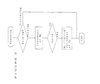
- the rounding unit is to execute rounding operation of a floating point data of 32 bit length which consists of a coding part of one bit length, a mantissa part of 24 bit length and an exponent part of 7 bit length.
- a rounding unit includes a first mantissa part register 101 to which a data M B representing the mantissa part of a floating point data before the rounding operation is executed is transferred from an arithmetic unit (not shown in the drawing) through a data bus 102.
- the first mantissa part register 101 is coupled to a mantissa part data bus 103.
- the first mantissa part register 101 may store a data representing the mantissa part of 24 bit length of a floating point data before the rounding operation is executed and transfer the same to the mantissa part data bus 103.
- a second mantissa part register 104 is also coupled with the mantissa part data bus 103 from which a data of 24 bit length may be transferred and stored therein.
- the second mantissa part register 104 is for storing a data M A representing the mantissa part of a floating point data after the rounding operation is completed.
- second mantissa part register 104 is of 24 bit length and coupled to the data bus 102 so as to transfer the rounded mantissa part data M A to the arithmetic unit.
- the rounding unit shown in Fig. 3 further includes a mantissa part incrementer 105 coupled to the mantissa part data bus 103 from which a data of 24 bit length may be set therein.
- the mantissa part inorementer 103 increments the data by "1" and, when an overflow occurs in the increment operation, it generates a carry signal 106. The thus incremented data may be transferred to the mantissa part data bus 103,
- the rounding unit further includes a constant register 107 coupled to the mantissa part data bus 103.
- the constant register 103 stores a constant data of 24 bit length in which the most significant bit is "1" and the other bits are "0".
- the rounding unit further includes a first exponent part register 108, a second exponent part register 109 and an exponent part incrementer 110.
- the data representing the exponent part of the floating point data has 7 bit length.
- the first and second exponent part register 108 and 109 can store a data of 7 bit length.
- the first exponent part register 108 receives a data E B representing the exponent part of the result of the arithmetic processing of floating point data before the rounding operation is executed from the arithmetic unit (not shown in the drawings), and it is also coupled to an exponent part data bus 111 so as to output the data Eg to the exponent part data bus 111.
- the second exponent part register 109 is for storing a data E A representing the exponent part of the floating point data after the rounding operation is completed.
- the second exponent part register 109 is coupled to the exponent part data bus 111 to receive therefrom the data.
- the exponent part incrementer 110 is coupled to the exponent part data bus 111 to receive an exponent part data therefrom and to output an incremented exponent part data thereto.
- the exponent part incrementer is an adder of 7 bit length to increment the inputted exponent part data by "1" . That is, "1" is added to the least significant of the exponent part data.
- the rounding unit shown in fig. 3 further includes a judging circuit 112 and a selection circuit 113.
- the judging circuit 112 is coupled to the data bus 102 to receive an information for judging whether the rounding operation is raising or truncating.
- the judging circuit 112 is connected to the selection circuit 113 by a line 114 through which a judging signal is inputted to the selection circuit 112.
- the selection circuit 112 receives a carry signal 106 at a first input and a judging signal 114 at a second input.
- the selection circuit 113 is connected to the mantissa part incrementer 105 via a line 115 for outputting a signal R l , to the constant register 107 and the exponent part incrementer 110 via a line 116 for outputting a signal R 2 , to the first mantissa part register 101 via a line 117 for outputting a signal R 3 and to the first exponent part register 108 via a line 118 for outputting a signal R 4 .
- the selection circuit 113 decides to output either of the signals R 1 , R 2 , R 3 and R 4 .
- the signal R 1 is to order to the mantissa incrementer 105 to output the incremented mantissa part data to the mantissa part data bus 103.
- the signal R 2 is to order to the constant register 107 and the exponent part inorementer 110 respectively to output the constant data to the mantissa part data bus 103 and the incremented exponent part data to the exponent part data bus 111.
- the signal R 3 is to order to the first mantissa part register 101 to output the mantissa part data M B to the mantissa part data bus 103, and the signal R 4 is to order to the first exponent part register 108 to output the exponent part data E B to the exponent part data bus 111.
- The'selection of the signals R l , R 2 , R 3 and R 4 made by the selection circuit 113 is illustrated in Table II.
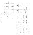
- Fig. 3 shows a timing chart of the operation of the rounding unit.
- T 1 and T 2 indicate two subsequent periodic cycles generated by a clock (not shown in the drawings) to synchronize the operation of the rounding unit.
- Each clock cycle is divided into two periods by pulses ⁇ 1 and ⁇ 2 .
- pulse ⁇ 1 is at the high level during the second half period of each clock cycle while pulse ⁇ 2 is at the high level during the first half period of each clock cycle.
- the mantissa part M B and the exponent part E B of the result of the arithmetic processing of floating point data are respectively inputted to the first mantissa part register 101 and the first exponent part register 108 during the period ⁇ 2 of the cycle T 1 through the data bus 102.
- the first mantissa part register 101 and the first exponent part register 108 transfer the mantissa part data M B and the exponent part data E B respectively to the mantissa part data bus 103 and the exponent part data bus 111.
- the mantissa part incrementer 105 and the exponent part incrementer 110 receive and latch the mantissa part data M B and the exponent part data Eg respectively through the mantissa part data bus 103 and the exponent part data bus 111.
- increment of the mantissa and exponent pacts M B and E B and the selection of the signals by the selection circuit 113 are executed. That is, the mantissa part incrementer 105 increments by "1" the mantissa part data M B on which the rounding operation has not been executed. The mantissa part incrementer 105 outputs a carry signal "1" when the increment of the mantissa part data M B overflows the most significant bit, and it outputs a signal "0" when the carry does not occur. The exponent part incrementer 110 increments by "1" the exponent part data E B on which the rounding operation has not been executed.
- the selection circuit receives a carry signal 106 from the mantissa part incrementer 105 and a judging signal 114 from the judging circuit 112. Based on these input signals, the selection circuit 113 selects either of the signals R 1 , R 2 , R 3 and R 4 , according to the logic illustrated in Table II.
- the selection circuit 113 selects the signals R3 and R 4 .
- the first mantissa part register 101 transfers the data M B to the second mantissa part register 14 through the mantissa part data bus 103 according to the signal R 3
- the first exponent part register 108 transfers the data E B to the second exponent part register 109 through the exponent part data bus 111.
- the selection circuit selects the signals R1 and R 4 .
- the mantissa part incrementer 105 and the first exponent part register 108 are actuated by the signals R 1 and R 4 respectively to transfer the incremented data to the mantissa part data bus 103 and transfer the exponent part data Eg to the exponent part data bus 111.
- the second mantissa part register 104 and the second exponent part register 109 read the data present respectively in the mantissa part data bus 103 and the exponent part data bus 111.
- the selection circuit 113 selects the signal R 2 which orders to the constant regisrer 107 and the exponent part inorementer 110 to output the data to the mantissa part data bus 103 and the exponent part data bus 111, respectively.
- the constant register 107 and the exponent part incrementer are actuated by the signals R 1 and R 2 respectively to transfer the constant data to the mantissa part data bus 103 and transfer the incremented exponent part data to the exponent part data bus 111.
- the second mantissa part register 104 and the second exponent part register 109 read the data present respectively in the mantissa part data bus 103 and the exponent part data bus 111. That is, the rounded mantissa part data M A which is now held in the second mantissa part register 104 is a constant data in which the most significant bit is "1" and the other bits are "0".
- the rounded exponent part data E A which is held in the second exponent part register 109 is a data obtained by incrementing by "1" the exponent part data E B .
- the rounding operation of floating point data can be executed within two clock cycles up to the storing of the rounded data in the registers 104 and 109.
- the rounding operation can be conducted at a very high speed.
- the second mantissa part register 104 and the second exponent part register 109 transfer respectively the data M A and E A to the arithmetic unit through the data bus 102.
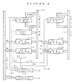
- the second example of the rounding unit according to the present invention will be explained with reference to Figs. 5 and 6.
- the rounding unit of the present example is similar to that shown in F ig. 3 except that an adjusting means is employed in lieu of the constant register 107 shown in Fig. 3 and that the logic of the selection circuit 113 is different from that of the selection circuit 113 of the rounding unit shown in Fig. 3.
- same numerical references are used as in F ig. 3 to indicate the same or corresponding elements.
- the rounding unit of the second example includes an adjusting means 120 having an input connected to the output of the mantissa part incrementer 105 and an output coupled to the mantissa part data bus 103.
- the output of the mantissa part incrementer 105 is not coupled with the mantissa part data bus 103.
- the selection circuit 113 receives at an input the carry signal 106 from the mantissa part incrementer 105 and at another input a judging signal 114 from the judging circuit 112. But, the output of the selection circuit 113 is connected to the adjusting means 120 for outputting a signal R 1 , to the exponent part incrementer 110 for outputting a signal R 2 , to the first mantissa part register 101 for outputting a signal R 3 and to the first exponent part register 108 for outputting a signal R 4 .
- the adjusting means 120 is connected at an input thereof to the output of the mantissa part incrementer 105 and receives at another input thereof the carry signal 106 from the mantissa part incrementer 105.
- the adjusting means 120 modifies the incremented data by adding the carry signal 106 to the most significant bit of the incremented mantissa part data. That is, when the carry signal is "1" which means that a carry occurs due to the increment of the mantissa part data, the adjusting means 120 modifies the incremented data to "10 ... 0".
- the mantissa part data thus modified by tha adjusting means 120 becomes a constant data in which the most significant bit is "1" and the other bits are "0".
- the carry signal is "0" which means that a carry does not occur, in fact, the adjusting means does not modify the incremented mantissa part data.
- the selection circuit 113 receives the carry signal 106 and the judging signal 114 and selects the signals from R 1 , R 2 , R 3 and R 4 according to a logic illustrated in Table III.
- the operation of the rounding unit shown in Fig. 5 is similar to that of the rounding unit shown in Fig. 3 except when the judging signal 114 indicates that the rounding operation is raising.
- the selection circuit selects the signals R 1 and R 4 .
- the adjusting means 120 and the first exponent part register 108 are actuated by the signals R 1 and R 4 respectively to transfer the adjusted data to the mantissa part data bus 103 and transfer the exponent part data Eg to the exponent part data bus 111.
- the adjusted mantissa part data remains unchanged.
- the mantissa part data M A stored and held in the second mantissa part register 104 is equal to the mantissa part data M B incremented by "1".
- the selection circuit 113 selects the signals R 1 and R 2 which order to the adjusting means 120 and the exponent part incrementer 110 to output the data to the mantissa part data bus 103 and the exponent part data bus 110, respectively.
- the adjusting means 120 and the exponent part incrementer 110 are actuated by the signals R 1 and R 2 respectively to transfer the adjusted incremented data to the mantissa part data bus 103 and transfer the incremented exponent part data to the exponent part data bus 111.
- the second mantissa part register 104 and the second exponent part register 109 read the data present respectively in the mantissa part data bus 103 and the exponent part data bus 111. That is, the rounded mantissa part data MA which is now held in the second mantissa part register 104 is the adjusted incremented data, which is equal to a constant data in which the most significant bit is "1" and the other bits are "0".
- the rounded exponent part data E A which is held in the second exponent part register 109 is a data obtained by incrementing by "1" the exponent part data Eg.
- the rounding unit according to the present invention can process at a high speed floating point data of any form without checking the presence of a carry by a software. Further, the rounding unit of the present invention can be fabricated by hardware circuits which are simple in construction and thus it is very useful for rounding operation of floating point data of high speed.
Abstract
Description
- The present invention relates to a rounding unit, and more particularly to a rounding unit for use in the arithmetic processing operation of floating point data.
- A floating point data is represented by an. exponent part and a mantissa part. That is, a floating point data A is represented by M x 2E where E represents the exponent part and M indicates the mantissa part. When floating point data are processed by an arithmetic unit, their exponent parts and mantissa parts are in general independently processed, respectively.
- In the arithmetic processing operation of floating point data, however, mantissa part data which have a data length exceeding the predetermined word length for the mantissa part are often treated. For example, in the case of the multiplication of floating point data, multiplication is conducted with the mantissa parts and possibly results in a data having a data length twice longet than the word length which is predetermined for the mantissa part. Thus, an operation for adjusting the data length of the resulted mantissa part data with the predetermined word length is required to complete the processing. Such an operation is called "rounding operation".
- The computer which processes floating point data is usually equipped with a means which can temporarily store the data underflowing the least significant bit of the mantissa part. In accordance with the ordered rounding mode, the underflowing data is rounded by, for example, raising or truncating the. same, to complete the arithmetic processing operation.
- The rounding mode includes a rounding to a nearest value, a rounding in the negative direction, a rounding in the positive direction, and a rounding in the direction toward zero. But the rounding operation includes only two cases, that is to raise one unit to the place of the least significant bit of the mantissa part and to truncate the value underflowing the least significant bit of the mantissa part. Namely, the rounding operation can be summarized as modifying the result of the arithmetic operation by adding "1" to the least significant bit of the mantissa part or truncating the underflowing value, depending upon the mode of rounding operation and the result of the arithmetic processing.
- However, there is an exception which can not be summarized as above. Such an exception is illustrated in Fig. 1. In this exceptional case, a mantissa part data, in which all of the bits are "1", is obtained as a result of the arithmetic processing, as shown in Fig. 1 (A). If such a mantissa part data is incremented by "1" by the rounding operation, the incremented data overflows the most significant bit of the mantissa part so that all of the bits in the mantissa part become "0" as shown in Fig. 1 (B). Thus an adjustment must be made to the mantissa part and to the exponent part. That is, the mantissa part must be a constant value in which the most significant bit is "1" and the other bits are "0", while the exponent, part is incremented by "1" as shown in Fig. 1 (C).
- Accordingly, the rounding operation must always be conducted to cover such an exception.
- In the prior art, the rounding operation is conducted following to an operation flow shown in Fig. 2.
- First, it should be judged whether the rounding operation is raising or truncating. If the operation is raising, the mantissa part MB is incremented by "1" and then it is also judged whether or not a carry occurs due to the increment of the mantissa part MB. These operations have been conducted by a program in the prior art. But, in the case of processing a number of floating point data, checking operation of a carry signal must be conducted each time the increment operation of the mantissa part is conducted, even if the exception described above rarely occurs. Then, the period of time for the rounding operation is prolonged because of the checking of the carry signal.
- Further, in case a carry occurs as a result of the increment of the mantissa part, both the mantissa part and the exponent part must be adjusted, which causes to further prolong the period of time for the rounding operation.
- It is a main object of the present invention to resolve the above described problem of the prior art, and more particularly to execute the rounding operation at a high speed.
- It is an object of the present invention to provide a rounding unit for use in arithmetic processing of floating point data, which operates at a high speed.
- According to the present invention, there is provided a rounding unit for use in arithmetic processing of floating point data, comprising:
- a mantissa part register for storing the mantissa part of the floating point data,
- an exponent part register for storing the exponent part of the floating point data;
- a judging circuit for judging whether the rounding operation is raising or truncating,
- a mantissa part inorementer for incrementing the mantissa part of the floating point data and outputting a carry signal when it is overflowed,
- an exponent part incrementer for incrementing the exponent part of the floating point data; and
- a selection circuit which, in response to the carry signal from the mantissa part incrementer and the judging signal from the judging circuit, orders to the mantissa part register to store a constant data of which the most significant bit is "1" and the other bits are "0", when the rounding operation is raising and the carry signal is present.
- According to an embodiment of the present invention, the mantissa part register includes a first mantissa part register for storing the mantissa part of the floating point data before the rounding operation is conducted, a second mantissa part register for storing the mantissa part of the floating point data after the rounding operation is completed, and a constant register for storing the constant data. These registers are coupled to a mantissa part data bus.
- According to an preferred embodiment of the present invention, when the rounding operation is truncating, the selection circuit orders to the firat mantissa part register to output the data stored therein to the mantissa part data bus and the second mantissa part register to read the data present in the mantissa part busy when the rounding operation is raising, but the carry signal is absent, the selection circuit orders to the mantissa part incrementer to output the incremented data to the mantissa part data bus and the second mantissa part register to read the data present in the mantissa part data bus; and when the rounding operation is raising and the carry signal is present, the selection circuit orders to the constant register to output the constant data to the mantissa part data bus and the second mantissa part register to read the data present in the mantissa data bus.
- According to another embodiment of the invention, the rounding unit further includes an adjusting means connected to the mantissa part incrementer to receive the carry signal and the incremented data, and for modifying the incremented data by adding the carry signal to the most significant bit of the incremented data. In this embodiment, the selection circuit orders to the mantissa part register to read the modified data, when the rounding operation is raising.
- According to a still further embodiment of the present invention, the exponent part register includes a first exponent part register for storing the exponent part of the floating point data before the rounding operation is conducted, a second exponent part register for storing the exponent part of the floating point data after the rounding operation is completed.
- Other objects and aspects of the invention will become apparent from the following description of embodiments of the invention which will be made with reference to the accompanying drawings.
-
- Fig. 1 illustrates an exceptional case of the rounding operation of floating point data where an adjustment must be made tn the mantissa and exponent parts.
- Fig. 2 shows operation flow of the rounding operation of the prior art.
- Fig. 3 is a block diagram showing a rounding unit of an example according to the present invention.
- Fig. 4 is a timing chart showing an operation flow of the rounding unit shown in Fig. 3.
- Fig. 5 a block diagram showing a rounding unit of another example according to the present invention.
- Fig. 6 shows in detail the adjusting means of the rounding unit shown in Fig. 5.
- Now, before describing the examples of the present invention, the rounding operation of the mantissa part data is illustrated in Table 1.

- As illustrated in Table 1, when the rounding operation is to truncate the value underflowing the least significant bit of the non-rounded mantissa part data MB, both of the mantissa part data and the exponent part data are not changed. On the other hand, when the rounding operation is to raise a unit to the place of the least signifioant bit of the mantissa part, that is, to add "1" to the least significant bit of the mantissa part data, either of two different operations is to be conducted depending upon the result of the increment of the mantissa part data. That is, when a carry operation, is to be conducted to the exponent part due to the increment of the mantissa part data, the mantissa data must be a constant data of "1 0 ... 0" and the exponent part data must be incremented by "1". When a carry does not occur, the mantissa part data is incremented by "1" and the exponent part data remains unchanged.
- With the above in the mind, a preferred example of the present invention will be described with reference to Fig. 3.
- In the first example which will be explained with reference to Fig. 3, the rounding unit is to execute rounding operation of a floating point data of 32 bit length which consists of a coding part of one bit length, a mantissa part of 24 bit length and an exponent part of 7 bit length.
- As shown in Fig. 3, a rounding unit according to the present invention includes a first
mantissa part register 101 to which a data MB representing the mantissa part of a floating point data before the rounding operation is executed is transferred from an arithmetic unit (not shown in the drawing) through adata bus 102. On the other hand, the firstmantissa part register 101 is coupled to a mantissapart data bus 103. Thus, the firstmantissa part register 101 may store a data representing the mantissa part of 24 bit length of a floating point data before the rounding operation is executed and transfer the same to the mantissapart data bus 103. - A second
mantissa part register 104 is also coupled with the mantissapart data bus 103 from which a data of 24 bit length may be transferred and stored therein. The secondmantissa part register 104 is for storing a data MA representing the mantissa part of a floating point data after the rounding operation is completed. Thus, secondmantissa part register 104 is of 24 bit length and coupled to thedata bus 102 so as to transfer the rounded mantissa part data MA to the arithmetic unit. - The rounding unit shown in Fig. 3 further includes a
mantissa part incrementer 105 coupled to the mantissapart data bus 103 from which a data of 24 bit length may be set therein. Themantissa part inorementer 103 increments the data by "1" and, when an overflow occurs in the increment operation, it generates acarry signal 106. The thus incremented data may be transferred to the mantissapart data bus 103, - The rounding unit further includes a
constant register 107 coupled to the mantissapart data bus 103. Theconstant register 103 stores a constant data of 24 bit length in which the most significant bit is "1" and the other bits are "0". - For rounding operation of a data representing the exponent part of the result of the arithmetic processing of floating point data, the rounding unit further includes a first
exponent part register 108, a secondexponent part register 109 and anexponent part incrementer 110. As mentioned above, the data representing the exponent part of the floating point data has 7 bit length. Then, the first and secondexponent part register exponent part register 108 receives a data EB representing the exponent part of the result of the arithmetic processing of floating point data before the rounding operation is executed from the arithmetic unit (not shown in the drawings), and it is also coupled to an exponentpart data bus 111 so as to output the data Eg to the exponentpart data bus 111. On the other hand, the secondexponent part register 109 is for storing a data EA representing the exponent part of the floating point data after the rounding operation is completed. The secondexponent part register 109 is coupled to the exponentpart data bus 111 to receive therefrom the data. - The
exponent part incrementer 110 is coupled to the exponentpart data bus 111 to receive an exponent part data therefrom and to output an incremented exponent part data thereto. The exponent part incrementer is an adder of 7 bit length to increment the inputted exponent part data by "1" . That is, "1" is added to the least significant of the exponent part data. - The rounding unit shown in fig. 3 further includes a judging
circuit 112 and aselection circuit 113. The judgingcircuit 112 is coupled to thedata bus 102 to receive an information for judging whether the rounding operation is raising or truncating. The judgingcircuit 112 is connected to theselection circuit 113 by aline 114 through which a judging signal is inputted to theselection circuit 112. Theselection circuit 112 receives acarry signal 106 at a first input and a judgingsignal 114 at a second input. On the other hand, theselection circuit 113 is connected to themantissa part incrementer 105 via aline 115 for outputting a signal Rl, to theconstant register 107 and theexponent part incrementer 110 via a line 116 for outputting a signal R2, to the firstmantissa part register 101 via aline 117 for outputting a signal R3 and to the firstexponent part register 108 via aline 118 for outputting a signal R4. - The
selection circuit 113 decides to output either of the signals R1, R2, R3 and R4. The signal R1 is to order to themantissa incrementer 105 to output the incremented mantissa part data to the mantissapart data bus 103. The signal R2 is to order to theconstant register 107 and theexponent part inorementer 110 respectively to output the constant data to the mantissapart data bus 103 and the incremented exponent part data to the exponentpart data bus 111. The signal R3 is to order to the firstmantissa part register 101 to output the mantissa part data MB to the mantissapart data bus 103, and the signal R4 is to order to the firstexponent part register 108 to output the exponent part data EB to the exponentpart data bus 111. - The'selection of the signals Rl, R2, R3 and R4 made by the
selection circuit 113 is illustrated in Table II.
- The operation of the rounding unit shown in Fig. 3 will be described with reference to Fig. 4 which shows a timing chart of the operation of the rounding unit.
- As shown in Fig. 4, T1 and T2 indicate two subsequent periodic cycles generated by a clock (not shown in the drawings) to synchronize the operation of the rounding unit. Each clock cycle is divided into two periods by pulses φ1 and φ2. pulse φ1 is at the high level during the second half period of each clock cycle while pulse φ2 is at the high level during the first half period of each clock cycle.
- First, the mantissa part MB and the exponent part EB of the result of the arithmetic processing of floating point data are respectively inputted to the first
mantissa part register 101 and the firstexponent part register 108 during the period φ2 of the cycle T1 through thedata bus 102. During a subsequent period φ1 of the cycle T1, the firstmantissa part register 101 and the firstexponent part register 108 transfer the mantissa part data MB and the exponent part data EB respectively to the mantissapart data bus 103 and the exponentpart data bus 111. Then, themantissa part incrementer 105 and theexponent part incrementer 110 receive and latch the mantissa part data MB and the exponent part data Eg respectively through the mantissapart data bus 103 and the exponentpart data bus 111. - During the period φ2 of the next cycle T2, increment of the mantissa and exponent pacts MB and EB and the selection of the signals by the
selection circuit 113 are executed. That is, themantissa part incrementer 105 increments by "1" the mantissa part data MB on which the rounding operation has not been executed. Themantissa part incrementer 105 outputs a carry signal "1" when the increment of the mantissa part data MB overflows the most significant bit, and it outputs a signal "0" when the carry does not occur. Theexponent part incrementer 110 increments by "1" the exponent part data EB on which the rounding operation has not been executed. - During the period φ2 of the cycle T2, the selection circuit receives a
carry signal 106 from themantissa part incrementer 105 and a judgingsignal 114 from the judgingcircuit 112. Based on these input signals, theselection circuit 113 selects either of the signals R1, R2, R3 and R4, according to the logic illustrated in Table II. - When the judging signal indicates that the rounding operation is to truncate the value underflowing the least significant bit of the mantissa part, the
selection circuit 113 selects the signals R3 and R4, During the period φ1 of the cycle T2, the firstmantissa part register 101 transfers the data MB to the second mantissa part register 14 through the mantissapart data bus 103 according to the signal R3, and the firstexponent part register 108 transfers the data EB to the secondexponent part register 109 through the exponentpart data bus 111. - When the judging signal indicates that the rounding is to raise one unit to the place of the least significant bit of the mantissa part and the
carry signal 106 is absent, the selection circuit selects the signals R1 and R4. During the period φ1 of the cycle T2, themantissa part incrementer 105 and the firstexponent part register 108 are actuated by the signals R1 and R4 respectively to transfer the incremented data to the mantissapart data bus 103 and transfer the exponent part data Eg to the exponentpart data bus 111. Then the secondmantissa part register 104 and the secondexponent part register 109 read the data present respectively in the mantissapart data bus 103 and the exponentpart data bus 111. - When the judging
signal 114 indicates that the rounding operation is to raise a unit to the place of the least significant bit of the mantissa part and the carry signal is "1", theselection circuit 113 selects the signal R2 which orders to theconstant regisrer 107 and theexponent part inorementer 110 to output the data to the mantissapart data bus 103 and the exponentpart data bus 111, respectively. During the period φ1 of the second cycle T2, theconstant register 107 and the exponent part incrementer are actuated by the signals R1 and R2 respectively to transfer the constant data to the mantissapart data bus 103 and transfer the incremented exponent part data to the exponentpart data bus 111. Then the secondmantissa part register 104 and the secondexponent part register 109 read the data present respectively in the mantissapart data bus 103 and the exponentpart data bus 111. That is, the rounded mantissa part data MA which is now held in the secondmantissa part register 104 is a constant data in which the most significant bit is "1" and the other bits are "0". The rounded exponent part data EA which is held in the secondexponent part register 109 is a data obtained by incrementing by "1" the exponent part data EB. - As explained in detail in above, the rounding operation of floating point data can be executed within two clock cycles up to the storing of the rounded data in the
registers - Then the second
mantissa part register 104 and the secondexponent part register 109 transfer respectively the data MA and EA to the arithmetic unit through thedata bus 102. - The second example of the rounding unit according to the present invention will be explained with reference to Figs. 5 and 6. The rounding unit of the present example is similar to that shown in Fig. 3 except that an adjusting means is employed in lieu of the
constant register 107 shown in Fig. 3 and that the logic of theselection circuit 113 is different from that of theselection circuit 113 of the rounding unit shown in Fig. 3. In Fig. 5, same numerical references are used as in Fig. 3 to indicate the same or corresponding elements. - As shown in Fig. 5, the rounding unit of the second example includes an adjusting means 120 having an input connected to the output of the
mantissa part incrementer 105 and an output coupled to the mantissapart data bus 103. In this example, the output of themantissa part incrementer 105 is not coupled with the mantissapart data bus 103. - Similar to the rounding unit shown in Fig. 3, the
selection circuit 113 receives at an input thecarry signal 106 from themantissa part incrementer 105 and at another input a judgingsignal 114 from the judgingcircuit 112. But, the output of theselection circuit 113 is connected to the adjusting means 120 for outputting a signal R1, to theexponent part incrementer 110 for outputting a signal R2, to the firstmantissa part register 101 for outputting a signal R3 and to the firstexponent part register 108 for outputting a signal R4. - As shown in Fig. 6 which shows in detail the adjusting means 120, the adjusting means 120 is connected at an input thereof to the output of the
mantissa part incrementer 105 and receives at another input thereof thecarry signal 106 from themantissa part incrementer 105. The adjusting means 120 modifies the incremented data by adding thecarry signal 106 to the most significant bit of the incremented mantissa part data. That is, when the carry signal is "1" which means that a carry occurs due to the increment of the mantissa part data, the adjusting means 120 modifies the incremented data to "10 ... 0". Thus, the mantissa part data thus modified by tha adjusting means 120 becomes a constant data in which the most significant bit is "1" and the other bits are "0". On the other hand, when the carry signal is "0" which means that a carry does not occur, in fact, the adjusting means does not modify the incremented mantissa part data. - Turning to Fig. 5, the
selection circuit 113 receives thecarry signal 106 and the judgingsignal 114 and selects the signals from R1, R2, R3 and R4 according to a logic illustrated in Table III.
- The operation of the rounding unit shown in Fig. 5 is similar to that of the rounding unit shown in Fig. 3 except when the judging
signal 114 indicates that the rounding operation is raising. - That is, when the judging signal indicates that the rounding is to raise one unit to the place of the least significant bit of the mantissa part and the
carry signal 106 is absent, the selection circuit selects the signals R1 and R4. During the period φ1 of the cycle T2, the adjusting means 120 and the firstexponent part register 108 are actuated by the signals R1 and R4 respectively to transfer the adjusted data to the mantissapart data bus 103 and transfer the exponent part data Eg to the exponentpart data bus 111. As mentioned above, however, in this case, the adjusted mantissa part data remains unchanged. Thus, the mantissa part data MA stored and held in the secondmantissa part register 104 is equal to the mantissa part data MB incremented by "1". - When the judging
signal 114 indicates that the rounding operation is to raise a unit to the place of the least significant bit of the mantisaa part and the carry signal is "1", theselection circuit 113 selects the signals R1 and R2 which order to the adjusting means 120 and theexponent part incrementer 110 to output the data to the mantissapart data bus 103 and the exponentpart data bus 110, respectively. During the period φ1 of the second cycle T2, the the adjusting means 120 and theexponent part incrementer 110 are actuated by the signals R1 and R2 respectively to transfer the adjusted incremented data to the mantissapart data bus 103 and transfer the incremented exponent part data to the exponentpart data bus 111. Then the secondmantissa part register 104 and the secondexponent part register 109 read the data present respectively in the mantissapart data bus 103 and the exponentpart data bus 111. That is, the rounded mantissa part data MA which is now held in the secondmantissa part register 104 is the adjusted incremented data, which is equal to a constant data in which the most significant bit is "1" and the other bits are "0". The rounded exponent part data EA which is held in the secondexponent part register 109 is a data obtained by incrementing by "1" the exponent part data Eg. - As explained in above, the rounding unit according to the present invention can process at a high speed floating point data of any form without checking the presence of a carry by a software. Further, the rounding unit of the present invention can be fabricated by hardware circuits which are simple in construction and thus it is very useful for rounding operation of floating point data of high speed.
- Although the examples are explained with the floating point data including a mantissa part of 24 bit length and an exponent part of 7 bit length, a rounding unit having a construction similar to the above examples can process floating point data of an enlarged format.
Claims (14)
Applications Claiming Priority (2)
| Application Number | Priority Date | Filing Date | Title |
|---|---|---|---|
| JP14469184A JPS6125245A (en) | 1984-07-12 | 1984-07-12 | Rounding process circuit |
| JP144691/84 | 1984-07-12 |
Publications (3)
| Publication Number | Publication Date |
|---|---|
| EP0168787A2 true EP0168787A2 (en) | 1986-01-22 |
| EP0168787A3 EP0168787A3 (en) | 1986-06-04 |
| EP0168787B1 EP0168787B1 (en) | 1991-12-04 |
Family
ID=15368019
Family Applications (1)
| Application Number | Title | Priority Date | Filing Date |
|---|---|---|---|
| EP85108715A Expired - Lifetime EP0168787B1 (en) | 1984-07-12 | 1985-07-12 | Rounding unit for use in arithmetic processing of floating point data |
Country Status (4)
| Country | Link |
|---|---|
| US (1) | US4796217A (en) |
| EP (1) | EP0168787B1 (en) |
| JP (1) | JPS6125245A (en) |
| DE (1) | DE3584797D1 (en) |
Cited By (1)
| Publication number | Priority date | Publication date | Assignee | Title |
|---|---|---|---|---|
| GB2262823A (en) * | 1991-12-23 | 1993-06-30 | Intel Corp | Apparatus and method for rounding operands. |
Families Citing this family (13)
| Publication number | Priority date | Publication date | Assignee | Title |
|---|---|---|---|---|
| WO1988008606A1 (en) * | 1987-04-28 | 1988-11-03 | Fujitsu Ten Limited | Method and apparatus for data transfer |
| JPH01169627A (en) * | 1987-12-25 | 1989-07-04 | Toshiba Corp | Highly accurate adding device |
| US4941119A (en) * | 1988-11-30 | 1990-07-10 | Control Data Corporation | Method and apparatus for predicting an overflow in an integer multiply |
| JP3076046B2 (en) * | 1989-01-31 | 2000-08-14 | 日本電気株式会社 | Exception detection circuit |
| US4994996A (en) * | 1989-02-03 | 1991-02-19 | Digital Equipment Corporation | Pipelined floating point adder for digital computer |
| US4941120A (en) * | 1989-04-17 | 1990-07-10 | International Business Machines Corporation | Floating point normalization and rounding prediction circuit |
| US4926370A (en) * | 1989-04-17 | 1990-05-15 | International Business Machines Corporation | Method and apparatus for processing postnormalization and rounding in parallel |
| US5278552A (en) * | 1989-10-23 | 1994-01-11 | Jeco Company Limited | Indicator control circuit |
| US4977535A (en) * | 1989-12-08 | 1990-12-11 | Motorola, Inc. | Method of computation of normalized numbers |
| EP0461241A4 (en) * | 1989-12-29 | 1993-09-01 | Motorola, Inc. | Binary floating point arithmetic rounding in conformance with ieee 754-1985 standard |
| US5339266A (en) * | 1993-11-29 | 1994-08-16 | Motorola, Inc. | Parallel method and apparatus for detecting and completing floating point operations involving special operands |
| US5563818A (en) * | 1994-12-12 | 1996-10-08 | International Business Machines Corporation | Method and system for performing floating-point division using selected approximation values |
| US5892697A (en) * | 1995-12-19 | 1999-04-06 | Brakefield; James Charles | Method and apparatus for handling overflow and underflow in processing floating-point numbers |
Citations (1)
| Publication number | Priority date | Publication date | Assignee | Title |
|---|---|---|---|---|
| US4338675A (en) * | 1980-02-13 | 1982-07-06 | Intel Corporation | Numeric data processor |
Family Cites Families (7)
| Publication number | Priority date | Publication date | Assignee | Title |
|---|---|---|---|---|
| FR2455315B1 (en) * | 1979-04-23 | 1986-10-24 | Anvar | METHOD FOR PROVIDING A NUMERICAL CALCULATION RESULT WITH THE NUMBER OF SIGNIFICANT ACCURATE NUMBERS IN THIS RESULT AND NUMERICAL CALCULATION DEVICE IMPLEMENTING THIS METHOD |
| US4295203A (en) * | 1979-11-09 | 1981-10-13 | Honeywell Information Systems Inc. | Automatic rounding of floating point operands |
| US4484259A (en) * | 1980-02-13 | 1984-11-20 | Intel Corporation | Fraction bus for use in a numeric data processor |
| US4468748A (en) * | 1981-06-11 | 1984-08-28 | Data General Corporation | Floating point computation unit having means for rounding the floating point computation result |
| US4528640A (en) * | 1982-07-13 | 1985-07-09 | Sperry Corporation | Method and a means for checking normalizing operations in a computer device |
| US4589067A (en) * | 1983-05-27 | 1986-05-13 | Analogic Corporation | Full floating point vector processor with dynamically configurable multifunction pipelined ALU |
| US4562553A (en) * | 1984-03-19 | 1985-12-31 | Analogic Corporation | Floating point arithmetic system and method with rounding anticipation |
-
1984
- 1984-07-12 JP JP14469184A patent/JPS6125245A/en active Granted
-
1985
- 1985-07-12 US US06/754,102 patent/US4796217A/en not_active Expired - Lifetime
- 1985-07-12 EP EP85108715A patent/EP0168787B1/en not_active Expired - Lifetime
- 1985-07-12 DE DE8585108715T patent/DE3584797D1/en not_active Expired - Fee Related
Patent Citations (1)
| Publication number | Priority date | Publication date | Assignee | Title |
|---|---|---|---|---|
| US4338675A (en) * | 1980-02-13 | 1982-07-06 | Intel Corporation | Numeric data processor |
Non-Patent Citations (3)
| Title |
|---|
| Electronic Design, 17 May 1984, pp. 144-151, WINDSOR et al: "Arithmetic duo excels in computing floating-point products" * |
| Electronics, 10 February 1982, pp. 149-152, WARE et al.: "C-MOS chip set streamlines floating-point processing" * |
| IEEE JOURNAL OF SOLID-STATE CIRCUITS, vol. SC-17, no. 5, October 1982, pages 898-907, IEEE, New York, US; F.A. WARE et al.: "64 Bit monolithic floating point processors" * |
Cited By (2)
| Publication number | Priority date | Publication date | Assignee | Title |
|---|---|---|---|---|
| GB2262823A (en) * | 1991-12-23 | 1993-06-30 | Intel Corp | Apparatus and method for rounding operands. |
| GB2262823B (en) * | 1991-12-23 | 1996-01-10 | Intel Corp | Apparatus and method for rounding operands |
Also Published As
| Publication number | Publication date |
|---|---|
| EP0168787B1 (en) | 1991-12-04 |
| EP0168787A3 (en) | 1986-06-04 |
| JPS6125245A (en) | 1986-02-04 |
| JPH0343645B2 (en) | 1991-07-03 |
| US4796217A (en) | 1989-01-03 |
| DE3584797D1 (en) | 1992-01-16 |
Similar Documents
| Publication | Publication Date | Title |
|---|---|---|
| US4591979A (en) | Data-flow-type digital processing apparatus | |
| US4949291A (en) | Apparatus and method for converting floating point data formats in a microprocessor | |
| EP0168787A2 (en) | Rounding unit for use in arithmetic processing of floating point data | |
| US4754421A (en) | Multiple precision multiplication device | |
| US4722068A (en) | Double precision multiplier | |
| EP0238090B1 (en) | Microcomputer capable of accessing internal memory at a desired variable access time | |
| US5457805A (en) | Microcomputer enabling high speed execution of product-sum operation | |
| EP0146984B1 (en) | Data processor for processing word wise receivable data | |
| EP0164451B1 (en) | An arithmetic processing unit for executing a floating point operation | |
| US5944775A (en) | Sum-of-products arithmetic unit | |
| US5402368A (en) | Computing unit and digital signal processor using the same | |
| US4685078A (en) | Dual incrementor | |
| US4878191A (en) | Multiplication circuit capable of operating at a high speed with a small amount of hardware | |
| US4761753A (en) | Vector processing apparatus | |
| US4866651A (en) | Method and circuit arrangement for adding floating point numbers | |
| US4974198A (en) | Vector processing system utilizing firm ware control to prevent delays during processing operations | |
| US4815019A (en) | Fast ALU equals zero circuit | |
| US4593377A (en) | High-speed processing method of line segment coordinates | |
| US5065353A (en) | Adder control method and adder control circuit | |
| EP0424838A2 (en) | Arithmetic circuit for calculating and accumulating absolute values of the difference between two numerical values | |
| EP0214836A1 (en) | Carry select adder | |
| EP0356940B1 (en) | Finite state machine | |
| JPS6260755B2 (en) | ||
| JPH0619700B2 (en) | Arithmetic unit | |
| JP2743685B2 (en) | Fixed-point processor |
Legal Events
| Date | Code | Title | Description |
|---|---|---|---|
| PUAI | Public reference made under article 153(3) epc to a published international application that has entered the european phase |
Free format text: ORIGINAL CODE: 0009012 |
|
| 17P | Request for examination filed |
Effective date: 19850712 |
|
| AK | Designated contracting states |
Designated state(s): DE FR GB |
|
| PUAL | Search report despatched |
Free format text: ORIGINAL CODE: 0009013 |
|
| AK | Designated contracting states |
Kind code of ref document: A3 Designated state(s): DE FR GB |
|
| 17Q | First examination report despatched |
Effective date: 19880927 |
|
| GRAA | (expected) grant |
Free format text: ORIGINAL CODE: 0009210 |
|
| AK | Designated contracting states |
Kind code of ref document: B1 Designated state(s): DE FR GB |
|
| REF | Corresponds to: |
Ref document number: 3584797 Country of ref document: DE Date of ref document: 19920116 |
|
| ET | Fr: translation filed | ||
| PLBE | No opposition filed within time limit |
Free format text: ORIGINAL CODE: 0009261 |
|
| STAA | Information on the status of an ep patent application or granted ep patent |
Free format text: STATUS: NO OPPOSITION FILED WITHIN TIME LIMIT |
|
| 26N | No opposition filed | ||
| PGFP | Annual fee paid to national office [announced via postgrant information from national office to epo] |
Ref country code: GB Payment date: 19940706 Year of fee payment: 10 |
|
| PGFP | Annual fee paid to national office [announced via postgrant information from national office to epo] |
Ref country code: DE Payment date: 19940923 Year of fee payment: 10 |
|
| PG25 | Lapsed in a contracting state [announced via postgrant information from national office to epo] |
Ref country code: GB Effective date: 19950712 |
|
| GBPC | Gb: european patent ceased through non-payment of renewal fee |
Effective date: 19950712 |
|
| PG25 | Lapsed in a contracting state [announced via postgrant information from national office to epo] |
Ref country code: DE Effective date: 19960402 |
|
| PGFP | Annual fee paid to national office [announced via postgrant information from national office to epo] |
Ref country code: FR Payment date: 20020709 Year of fee payment: 18 |
|
| PG25 | Lapsed in a contracting state [announced via postgrant information from national office to epo] |
Ref country code: FR Free format text: LAPSE BECAUSE OF NON-PAYMENT OF DUE FEES Effective date: 20040331 |
|
| REG | Reference to a national code |
Ref country code: FR Ref legal event code: ST |