EP0169045A2 - Connective tissue prosthesis - Google Patents
Connective tissue prosthesis Download PDFInfo
- Publication number
- EP0169045A2 EP0169045A2 EP85305034A EP85305034A EP0169045A2 EP 0169045 A2 EP0169045 A2 EP 0169045A2 EP 85305034 A EP85305034 A EP 85305034A EP 85305034 A EP85305034 A EP 85305034A EP 0169045 A2 EP0169045 A2 EP 0169045A2
- Authority
- EP
- European Patent Office
- Prior art keywords
- filaments
- prosthesis
- prosthesis according
- fine
- fine filaments
- Prior art date
- Legal status (The legal status is an assumption and is not a legal conclusion. Google has not performed a legal analysis and makes no representation as to the accuracy of the status listed.)
- Granted
Links
Images
Classifications
-
- A—HUMAN NECESSITIES
- A61—MEDICAL OR VETERINARY SCIENCE; HYGIENE
- A61F—FILTERS IMPLANTABLE INTO BLOOD VESSELS; PROSTHESES; DEVICES PROVIDING PATENCY TO, OR PREVENTING COLLAPSING OF, TUBULAR STRUCTURES OF THE BODY, e.g. STENTS; ORTHOPAEDIC, NURSING OR CONTRACEPTIVE DEVICES; FOMENTATION; TREATMENT OR PROTECTION OF EYES OR EARS; BANDAGES, DRESSINGS OR ABSORBENT PADS; FIRST-AID KITS
- A61F2/00—Filters implantable into blood vessels; Prostheses, i.e. artificial substitutes or replacements for parts of the body; Appliances for connecting them with the body; Devices providing patency to, or preventing collapsing of, tubular structures of the body, e.g. stents
- A61F2/02—Prostheses implantable into the body
- A61F2/08—Muscles; Tendons; Ligaments
-
- A—HUMAN NECESSITIES
- A61—MEDICAL OR VETERINARY SCIENCE; HYGIENE
- A61F—FILTERS IMPLANTABLE INTO BLOOD VESSELS; PROSTHESES; DEVICES PROVIDING PATENCY TO, OR PREVENTING COLLAPSING OF, TUBULAR STRUCTURES OF THE BODY, e.g. STENTS; ORTHOPAEDIC, NURSING OR CONTRACEPTIVE DEVICES; FOMENTATION; TREATMENT OR PROTECTION OF EYES OR EARS; BANDAGES, DRESSINGS OR ABSORBENT PADS; FIRST-AID KITS
- A61F2250/00—Special features of prostheses classified in groups A61F2/00 - A61F2/26 or A61F2/82 or A61F9/00 or A61F11/00 or subgroups thereof
- A61F2250/0014—Special features of prostheses classified in groups A61F2/00 - A61F2/26 or A61F2/82 or A61F9/00 or A61F11/00 or subgroups thereof having different values of a given property or geometrical feature, e.g. mechanical property or material property, at different locations within the same prosthesis
- A61F2250/0018—Special features of prostheses classified in groups A61F2/00 - A61F2/26 or A61F2/82 or A61F9/00 or A61F11/00 or subgroups thereof having different values of a given property or geometrical feature, e.g. mechanical property or material property, at different locations within the same prosthesis differing in elasticity, stiffness or compressibility
Definitions
- This invention relates to a connective tissue prosthesis, and in particular to a prosthesis for use in place of a natural ligament or tendon.
- tendon and ligament prostheses Numerous different constructions have been proposed for tendon and ligament prostheses. Early proposals were generally for prostheses in the form of a single load bearing element of a biocompatible material, and such constructions continue to be proposed. While such prostheses usually have the requisite tensile strength, their behaviour is very different from that of native collagenous soft tissue, because they display a substantially constant modulus of elasticity over a wide range of applied tensile loads. In contrast, a natural ligament or tendon displays a comparatively low modulus of elasticity under low tensile loads, and a greatly increased elastic modulus under high tensile loads. This means that natural ligaments and tendons are sufficiently resilient to provide enough movement to minimise the strain imposed on the connection with bone or soft tissue, but sufficiently resistant to large stresses to avoid excessive, and thus.damaging, movement of joints.
- British Patent Specification No. 1471837 discloses a tendon prosthesis consisting of a core and of a sheath.
- the preferred core consists of a knitted fabric or twisted fabric bundle embedded in an elastic oriented polymer. It is said that such a core gives a performance similar to that of a genuine tendon, and the prosthesis as a whole is said to be "physiologically inert".
- the present invention seeks to provide an implantable prosthesis with a mechanical response similar to that of native soft collagenous connective tissues, which is moreover capable of promoting a considerable degree of collagen fibrogenesis.
- a biocompatible connective tissue prosthesis comprising a first load bearing element and a bundle of fine filaments which are arranged to allow ingrowth of connective tissue, said filaments being of higher elastic modulus than the effective elastic modulus of the first element, and being attached to the first element at spaced points along their length, the length of filament between said points being greater than the unstressed length of the first element between said points, such that the filaments are substantially unstressed unless the load on the prosthesis exceeds a predetermined value.
- the high modulus material is available to be intertwined with collagen,following ingrowth of new tissue.
- the high modulus material should not be completely surrounded by the low modulus material (such as is the case in the prosthesis disclosed in Specification No. 1471837), because low modulus materials in general do not promote fibrogenesis.
- the prosthesis of the present invention is capable of non-linear elastic deformation so that a comparatively large elastic stretch is obtained on the.application of low tensile forces, but greatly increased forces produce comparatively little further deformation. Furthermore, in contrast to the prosthesis disclosed in Specification No. 1471837, there is substantially no shear interaction between the materials of different elastic modulus when the prosthesis is stretched as a whole.
- the material or materials used in the prosthesis according to the invention must be biocompatible in the sense of inducing no adverse biological reaction, and being well tolerated by fibroblasts. It is also preferable that the material or materials are readily sterilizable by commonly used methods such as ⁇ -irradiation, autoclaving and ethylene oxide treatment.
- the first load bearing element has an effective elastic modulus of from 0.1 to 2 MPa, for example 0.5 to 1.5 MPa
- the filaments preferably have a collective elastic modulus of from 100 to 3000 MPa, for example 1000 to 2000 MPa.
- the particular elastic modulus chosen for the first element and the filaments will depend on the use to which the prosthesis is to - be put. For example, a prosthesis for use in a child will generally have a lower elastic modulus than a prosthesis for use in an adult, because connective tissue of children is generally more elastic than that of adults.
- the term "effective elastic modulus", as used in relation to the first element, means the elastic modulus of the first element as a whole. This elastic modulus may be derived from the inherent properties of the material from which it is made. Thus, for example, the first element may comprise one or more substantially straight filaments of the desired elastic modulus, such as medical grade silicone rubber.
- the first element derives its effective elastic modulus not merely from the elastic modulus from which it is made, but also from the conformation in which this material is arranged.
- the first element may be in the form of a spring, such as a coil spring, of a material which has a relatively large elastic modulus, the desired elastic modulus being that of the spring as a whole.
- the linear elastic strain limit of the first ele-:: ment will generally be greater than 20%, while the linear elastic strain limit of the filaments is preferably at least 2 to 3%.
- the mechanical response of the prosthesis of the invention can be made to suit individual requirements not only by choosing materials having the desired elastic modulus and elastic strain limit, but also by varying the length of the filaments between the points of their attachment to the first element, relative to the relaxed length of the first element between those points.
- the fine filaments will be of such a length relative to the first element that the maximum degree to which the first element can be stretched without stressing the filaments is in the range 1 to 15%, and more preferably in the range 1 to 5%.
- the prosthesis may-be in the form of an elongate ligament or tendon prosthesis.
- a prosthesis is designed to bear tensile stresses essentially in a single direction, and may be referred to as a "one-dimensional" prosthesis.
- the invention is equally applicable to two-, or even three-dimensional prostheses, i.e. to prostheses which are designed to bear stresses in two or three mutually perpendicular directions.
- a ligament or tendon prosthesis may, if desired, be branched, the mechanical properties of each branch being tailored to match the mechanical properties of the branched ligament or tendon which the prosthesis is designed to replace.
- the fine filaments will generally be formed from a plastics material, such as a polyester or polyamide, for example nylon.
- a ligament or tendon prosthesis according to the invention preferably comprises from 50 to 1500 yarns, each consisting of from 20 to 100 fine filaments.
- the number of fine filaments to be used in any prosthesis depends on the overall strength, elastic modulus, cross sectional area and extent of elastic stretch required of the prosthesis, and on the corresponding properties of the individual fine filaments.
- the fine filaments preferably have a diameter in the range 8 to 20 microns.
- the fine filaments are provided in the form of filamentary yarns, these may be twisted or braided. In any such construction, however, care must be taken to ensure that the fine filaments are not so tightly packed that ingrowth of fresh collagenous tissue is prevented.
- the packing density of the fine filaments should preferably be slightly lower than that given by a close packed hexagonal arrangement of fine filaments.
- the fibrogenicity of the prosthesis may be further enhanced by coating the fine filaments with agents which promote infiltration and adhesion, such as fibronectin and/or heparin.
- the prosthesis may be sterilised, for example by gamma-irradiation, and may be hermetically sealed in a sterile envelope. One or both ends of the fine filaments may be collectively threaded through a surgical needle, so that the prosthesis is immediately ready for use by the surgeon.
- the present invention also provides a method of making the prosthesis described above, the method comprising stretching a first load bearing element by a predetermined amount and then fixing a bundle of filaments at two or more spaced points along the length of the first element, such that the filaments are unstressed unless the first element is stretched by said predetermined amount.
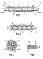
- a ligament prosthesis comprises a first load bearing element 1 in the form of a relatively thick silicone monofilament (e.g. SILASTIC silicone monofilament made by Dow Corning. SILASTIC is a Trade Mark).
- a bundle of fine polyester filaments 3, of 10 micron diameter, are connected to the first load bearing element 1 at spaced intervals as indicated at 5.
- the prosthesis is made as follows.
- the silicone monofilament 1 after washing in a detergent solution, is clamped between two clamps 7 and stretched so that the distance between two marker points AB is increased from the- rest length 1 to the desired stretched length l t .
- Fine filaments of polyester of length greater than It are then washed in detergent solution and laid around the pre-stretched silicone, and fastened to the silicone at the points 5. Fastening can be effected by using non-toxic biologically tolerable glue, surgical staples or by tying with additional yarns of polyester.
- the fine polyester filaments 3 should be unstressed at this stage, as shown in Figure 1.
- the prosthesis is removed from the clamps, so that a distance AB reverts to l o .
- the elastic modulus of the prosthesis at small deformation is given by the elastic modulus of the silicone monofilament, since the fine polyester filaments are unstressed.
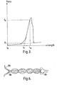
- the elastic modulus of the prosthesis is given essentially by the elastic modulus of the fine polyester filaments. This is illustrated graphically in Figure 3.
- the fine filaments begin to stretch, and the stress/strain curve shows a transition from the low modulus linear response given by the first element, to the higher modulus, essentially linear response given by the fine filaments.
- This higher modulus linear response is seen until the applied force reaches F e , at which point the length AB is given by 1 e , the linear elastic limit of the fine fila- ments.
- Increasing the applied force still further produces non-elastic deformation of the prosthesis, and then ultimate failure. It is therefore preferable to construct the prosthesis so that in use it is never stretched beyond the length l e .
- Figure 4 Illustrates a section through a ligament prosthesis in which the first load beiring element is constituted by a central SILASTIC monofilament 41 and eight further SILASTIC monofilaments 42 disposed equiangularly around the central monofilament.
- Fine polyester filaments 43 are arranged not only around the eight monofilaments 42, but also between these latter and the central monofilament 41.
- Figure 5 shows a section through a prosthesis in which the first load bearing element is constituted by two sheets of SILASTIC silicone rubber 51, in a layered arrangement with fine polyester filaments 53.
- the ends of the prosthesis may be inserted or fixed in connectors 64 to facilitate threading and fixation in surgical procedures.
- one or both ends of the protruding silicone monofilament may be cut off and the fine filament ends 66 prepared ready for suturing with surgical needles 68.
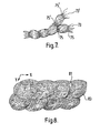
- the first load bearing element (not shown) is branched, with some of the fine filaments 73 being attached to one branch at 75, and other fine filaments 73' being attached to the other branch at 75'.
- the length of the fine filaments between the points 75, and the number of such filaments, need not necessarily be the same as the length and number of fine filaments between the points 75', so that the two branches display different mechanical properties.
- the first load bearing element comprises a membrane 81 of low elastic modulus material which is pre-stretched in two mutually perpendicular directions (represented by X and Y) before attaching two crossed but distinct sets of fine filaments which are oriented respectively in the X and Y directions.
Abstract
Description
- . This invention relates to a connective tissue prosthesis, and in particular to a prosthesis for use in place of a natural ligament or tendon.
- Numerous different constructions have been proposed for tendon and ligament prostheses. Early proposals were generally for prostheses in the form of a single load bearing element of a biocompatible material, and such constructions continue to be proposed. While such prostheses usually have the requisite tensile strength, their behaviour is very different from that of native collagenous soft tissue, because they display a substantially constant modulus of elasticity over a wide range of applied tensile loads. In contrast, a natural ligament or tendon displays a comparatively low modulus of elasticity under low tensile loads, and a greatly increased elastic modulus under high tensile loads. This means that natural ligaments and tendons are sufficiently resilient to provide enough movement to minimise the strain imposed on the connection with bone or soft tissue, but sufficiently resistant to large stresses to avoid excessive, and thus.damaging, movement of joints.
- Attempts have been made to produce prostheses which more closely mimic the mechanical properties of natural collagenous tissue. For example, British Patent Specification No. 1471837 discloses a tendon prosthesis consisting of a core and of a sheath. The preferred core consists of a knitted fabric or twisted fabric bundle embedded in an elastic oriented polymer. It is said that such a core gives a performance similar to that of a genuine tendon, and the prosthesis as a whole is said to be "physiologically inert".
- More recently, the trend has been towards prostheses which are not physiologically inert, but which on the contrary, elicit the positive physiological response of fibrogenesis. Such a prosthesis is described-in British Patent Specification No. 1602834. However, this prosthesis, being formed from a single material, suffers the same disadvantages as the earlier prior art prostheses as regards the nature of its response to increasing load.
- The present invention seeks to provide an implantable prosthesis with a mechanical response similar to that of native soft collagenous connective tissues, which is moreover capable of promoting a considerable degree of collagen fibrogenesis.
- According to the present invention there is provided a biocompatible connective tissue prosthesis, comprising a first load bearing element and a bundle of fine filaments which are arranged to allow ingrowth of connective tissue, said filaments being of higher elastic modulus than the effective elastic modulus of the first element, and being attached to the first element at spaced points along their length, the length of filament between said points being greater than the unstressed length of the first element between said points, such that the filaments are substantially unstressed unless the load on the prosthesis exceeds a predetermined value.
- Thus, in contrast to the prosthesis disclosed in Specification No. 1471837, the high modulus material is available to be intertwined with collagen,following ingrowth of new tissue. We have found that the high modulus material should not be completely surrounded by the low modulus material (such as is the case in the prosthesis disclosed in Specification No. 1471837), because low modulus materials in general do not promote fibrogenesis.
- The prosthesis of the present invention is capable of non-linear elastic deformation so that a comparatively large elastic stretch is obtained on the.application of low tensile forces, but greatly increased forces produce comparatively little further deformation. Furthermore, in contrast to the prosthesis disclosed in Specification No. 1471837, there is substantially no shear interaction between the materials of different elastic modulus when the prosthesis is stretched as a whole.
- The material or materials used in the prosthesis according to the invention must be biocompatible in the sense of inducing no adverse biological reaction, and being well tolerated by fibroblasts. It is also preferable that the material or materials are readily sterilizable by commonly used methods such as γ -irradiation, autoclaving and ethylene oxide treatment.
- Preferably, the first load bearing element has an effective elastic modulus of from 0.1 to 2 MPa, for example 0.5 to 1.5 MPa, and the filaments preferably have a collective elastic modulus of from 100 to 3000 MPa, for example 1000 to 2000 MPa. The particular elastic modulus chosen for the first element and the filaments will depend on the use to which the prosthesis is to - be put. For example, a prosthesis for use in a child will generally have a lower elastic modulus than a prosthesis for use in an adult, because connective tissue of children is generally more elastic than that of adults.
- The term "effective elastic modulus", as used in relation to the first element, means the elastic modulus of the first element as a whole. This elastic modulus may be derived from the inherent properties of the material from which it is made. Thus, for example, the first element may comprise one or more substantially straight filaments of the desired elastic modulus, such as medical grade silicone rubber.
- In an alternative construction, the first element derives its effective elastic modulus not merely from the elastic modulus from which it is made, but also from the conformation in which this material is arranged. Thus, the first element may be in the form of a spring, such as a coil spring, of a material which has a relatively large elastic modulus, the desired elastic modulus being that of the spring as a whole.
- The linear elastic strain limit of the first ele-:: ment will generally be greater than 20%, while the linear elastic strain limit of the filaments is preferably at least 2 to 3%.
- It will be appreciated that the mechanical response of the prosthesis of the invention can be made to suit individual requirements not only by choosing materials having the desired elastic modulus and elastic strain limit, but also by varying the length of the filaments between the points of their attachment to the first element, relative to the relaxed length of the first element between those points. Generally, the fine filaments will be of such a length relative to the first element that the maximum degree to which the first element can be stretched without stressing the filaments is in the
range 1 to 15%, and more preferably in therange 1 to 5%. - The prosthesis may-be in the form of an elongate ligament or tendon prosthesis. Such a prosthesis is designed to bear tensile stresses essentially in a single direction, and may be referred to as a "one-dimensional" prosthesis. It will be understood, however, that the invention is equally applicable to two-, or even three-dimensional prostheses, i.e. to prostheses which are designed to bear stresses in two or three mutually perpendicular directions. Moreover, a ligament or tendon prosthesis may, if desired, be branched, the mechanical properties of each branch being tailored to match the mechanical properties of the branched ligament or tendon which the prosthesis is designed to replace.
- The fine filaments will generally be formed from a plastics material, such as a polyester or polyamide, for example nylon. A ligament or tendon prosthesis according to the invention preferably comprises from 50 to 1500 yarns, each consisting of from 20 to 100 fine filaments. The number of fine filaments to be used in any prosthesis depends on the overall strength, elastic modulus, cross sectional area and extent of elastic stretch required of the prosthesis, and on the corresponding properties of the individual fine filaments. The fine filaments preferably have a diameter in the range 8 to 20 microns.
- When the fine filaments are provided in the form of filamentary yarns, these may be twisted or braided. In any such construction, however, care must be taken to ensure that the fine filaments are not so tightly packed that ingrowth of fresh collagenous tissue is prevented. The packing density of the fine filaments should preferably be slightly lower than that given by a close packed hexagonal arrangement of fine filaments.
- The fibrogenicity of the prosthesis may be further enhanced by coating the fine filaments with agents which promote infiltration and adhesion, such as fibronectin and/or heparin.
- The prosthesis may be sterilised, for example by gamma-irradiation, and may be hermetically sealed in a sterile envelope. One or both ends of the fine filaments may be collectively threaded through a surgical needle, so that the prosthesis is immediately ready for use by the surgeon.
- The present invention also provides a method of making the prosthesis described above, the method comprising stretching a first load bearing element by a predetermined amount and then fixing a bundle of filaments at two or more spaced points along the length of the first element, such that the filaments are unstressed unless the first element is stretched by said predetermined amount.
- A prosthesis according to the invention, and a method of making such a prosthesis, are now disclosed, by way of example, with reference to the accompanying drawings, in which:-
- Figure 1 is a schematic view of a prosthesis in a partially stretched state,
- Figure 2 is a schematic view of the prosthesis of Figure 1 in a relaxed state,
- Figure 3 is a graph showing the stress/strain curve of the prosthesis of Figure 1,
- Figures 4 and 5 show schematic sections through alternative constructions of prosthesis,
- Figure 6 shows a prosthesis provided with needles for suturing,
- Figure 7 illustrates a branched prosthesis, and
- Figure 8 shows a prosthesis adapted for receiving a load in two mutually perpendicular directions.
- Referring to the drawings, a ligament prosthesis comprises a first
load bearing element 1 in the form of a relatively thick silicone monofilament (e.g. SILASTIC silicone monofilament made by Dow Corning. SILASTIC is a Trade Mark). A bundle of fine polyester filaments 3, of 10 micron diameter, are connected to the firstload bearing element 1 at spaced intervals as indicated at 5. - The prosthesis is made as follows. The
silicone monofilament 1, after washing in a detergent solution, is clamped between two clamps 7 and stretched so that the distance between two marker points AB is increased from the-rest length 1 to the desired stretched length lt. Fine filaments of polyester of length greater than It are then washed in detergent solution and laid around the pre-stretched silicone, and fastened to the silicone at thepoints 5. Fastening can be effected by using non-toxic biologically tolerable glue, surgical staples or by tying with additional yarns of polyester. The fine polyester filaments 3 should be unstressed at this stage, as shown in Figure 1. - After the fine polyester filaments 3 are suitably attached to the
silicone monofilament 1, the prosthesis is removed from the clamps, so that a distance AB reverts to lo. - In use, the elastic modulus of the prosthesis at small deformation is given by the elastic modulus of the silicone monofilament, since the fine polyester filaments are unstressed. As the deformation of the prosthesis increases so that the length AB exceeds lt, the elastic modulus of the prosthesis is given essentially by the elastic modulus of the fine polyester filaments. This is illustrated graphically in Figure 3.
- As Figure 3 shows, applying an increasing tensile force to the prosthesis gives a comparatively large, and essentially linear increase in length of the prosthesis until the force reaches a value Ft. This is the force required to stretch the distance between the markers AB from lO to It.
- As the applied force is increased, the fine filaments begin to stretch, and the stress/strain curve shows a transition from the low modulus linear response given by the first element, to the higher modulus, essentially linear response given by the fine filaments. This higher modulus linear response is seen until the applied force reaches Fe, at which point the length AB is given by 1e, the linear elastic limit of the fine fila- ments. Increasing the applied force still further produces non-elastic deformation of the prosthesis, and then ultimate failure. It is therefore preferable to construct the prosthesis so that in use it is never stretched beyond the length le.
- It is not necessary for the first load bearing element to be constituted by a single monofilament or for such a monofilament to be located at the centre of the bundle of fine filaments. A plurality of elements of circular, rectangular, square or other cross sections may be dispersed among the fine filaments. For example, Figure 4 Illustrates a section through a ligament prosthesis in which the first load beiring element is constituted by a central SILASTIC monofilament 41 and eight
further SILASTIC monofilaments 42 disposed equiangularly around the central monofilament.Fine polyester filaments 43 are arranged not only around the eightmonofilaments 42, but also between these latter and the central monofilament 41. - Figure 5 shows a section through a prosthesis in which the first load bearing element is constituted by two sheets of
SILASTIC silicone rubber 51, in a layered arrangement withfine polyester filaments 53. - As shown in Figure 6, the ends of the prosthesis may be inserted or fixed in
connectors 64 to facilitate threading and fixation in surgical procedures. Alternatively, one or both ends of the protruding silicone monofilament may be cut off and the fine filament ends 66 prepared ready for suturing withsurgical needles 68. - In the embodiment shown in Figure 7, the first load bearing element (not shown) is branched, with some of the
fine filaments 73 being attached to one branch at 75, and other fine filaments 73' being attached to the other branch at 75'. The length of the fine filaments between thepoints 75, and the number of such filaments, need not necessarily be the same as the length and number of fine filaments between the points 75', so that the two branches display different mechanical properties. - For replacement of tissues which bear biaxial stresses, the form shown in Figure 8 may be adopted. In this construction the first load bearing element comprises a
membrane 81 of low elastic modulus material which is pre-stretched in two mutually perpendicular directions (represented by X and Y) before attaching two crossed but distinct sets of fine filaments which are oriented respectively in the X and Y directions.
Claims (16)
Priority Applications (2)
| Application Number | Priority Date | Filing Date | Title |
|---|---|---|---|
| AT85305034T ATE67925T1 (en) | 1984-07-16 | 1985-07-15 | PROSTHESIS FOR CONNECTIVE TISSUE. |
| MYPI87001216A MY100075A (en) | 1984-07-16 | 1987-08-06 | Connective tissue prosthesis |
Applications Claiming Priority (2)
| Application Number | Priority Date | Filing Date | Title |
|---|---|---|---|
| GB848418018A GB8418018D0 (en) | 1984-07-16 | 1984-07-16 | Connective tissue prosthesis |
| GB8418018 | 1984-07-16 |
Publications (3)
| Publication Number | Publication Date |
|---|---|
| EP0169045A2 true EP0169045A2 (en) | 1986-01-22 |
| EP0169045A3 EP0169045A3 (en) | 1988-01-13 |
| EP0169045B1 EP0169045B1 (en) | 1991-10-02 |
Family
ID=10563931
Family Applications (1)
| Application Number | Title | Priority Date | Filing Date |
|---|---|---|---|
| EP85305034A Expired - Lifetime EP0169045B1 (en) | 1984-07-16 | 1985-07-15 | Connective tissue prosthesis |
Country Status (13)
| Country | Link |
|---|---|
| US (1) | US4642119A (en) |
| EP (1) | EP0169045B1 (en) |
| AT (1) | ATE67925T1 (en) |
| AU (1) | AU575664B2 (en) |
| CA (1) | CA1236652A (en) |
| DE (1) | DE3584270D1 (en) |
| DK (1) | DK164440C (en) |
| GB (1) | GB8418018D0 (en) |
| HK (1) | HK2292A (en) |
| IN (1) | IN163863B (en) |
| MY (1) | MY100075A (en) |
| NZ (1) | NZ212639A (en) |
| SG (1) | SG98191G (en) |
Cited By (17)
| Publication number | Priority date | Publication date | Assignee | Title |
|---|---|---|---|---|
| US4662886A (en) * | 1984-06-04 | 1987-05-05 | A. W. Showell (Surgicraft) Limited | Surgical element |
| EP0238263A1 (en) * | 1986-03-14 | 1987-09-23 | SMITH & NEPHEW RICHARDS, INC. | Prosthetic ligament |
| EP0358324A1 (en) * | 1988-08-05 | 1990-03-14 | Ellis Developments Limited | Prosthetic ligament |
| WO1990012551A1 (en) * | 1989-04-27 | 1990-11-01 | Gazielly Dominique Francois | Device for reinforcing and sustaining the cap of the rotators of a human shoulder joint |
| US4990158A (en) * | 1989-05-10 | 1991-02-05 | United States Surgical Corporation | Synthetic semiabsorbable tubular prosthesis |
| US5056530A (en) * | 1988-12-15 | 1991-10-15 | University Of Cincinnati | Method of measuring axial force in mammalian fibrous tissue and device |
| US5147400A (en) * | 1989-05-10 | 1992-09-15 | United States Surgical Corporation | Connective tissue prosthesis |
| US5156565A (en) * | 1989-05-03 | 1992-10-20 | Pierre Jonnard | Process to prepare natural casings in the pork butcher's trade and the device to implement it |
| US5197983A (en) * | 1988-04-19 | 1993-03-30 | W. L. Gore & Associates, Inc. | Ligament and tendon prosthesis |
| US5217495A (en) * | 1989-05-10 | 1993-06-08 | United States Surgical Corporation | Synthetic semiabsorbable composite yarn |
| FR2687911A1 (en) * | 1992-03-02 | 1993-09-03 | Periode Sa | Ligament prosthesis with protective sheet |
| FR2696337A1 (en) * | 1992-10-07 | 1994-04-08 | Perrin Max | Artificial ligament made of synthetic material - has series of anchoring rings on end opposite stop head, allowing it to be trimmed to the correct length after fitting |
| FR2700111A1 (en) * | 1992-03-23 | 1994-07-08 | Cuisset Bertrand | Artificial ligament for prosthetic use |
| WO1994022395A1 (en) * | 1993-03-31 | 1994-10-13 | Surgicraft Limited | Artificial ligament |
| US5376118A (en) * | 1989-05-10 | 1994-12-27 | United States Surgical Corporation | Support material for cell impregnation |
| US5441508A (en) * | 1989-04-27 | 1995-08-15 | Gazielly; Dominique | Reinforcement and supporting device for the rotator cuff of a shoulder joint of a person |
| WO1996001600A1 (en) * | 1994-07-07 | 1996-01-25 | Bertrand Cuisset | Ligament prosthesis |
Families Citing this family (23)
| Publication number | Priority date | Publication date | Assignee | Title |
|---|---|---|---|---|
| US4792336A (en) * | 1986-03-03 | 1988-12-20 | American Cyanamid Company | Flat braided ligament or tendon implant device having texturized yarns |
| CH668900A5 (en) * | 1986-03-07 | 1989-02-15 | Sulzer Ag | ARTIFICIAL CROSSBAND FOR A KNEE JOINT. |
| GB8622563D0 (en) * | 1986-09-19 | 1986-10-22 | Amis A A | Artificial ligaments |
| EP0375729A4 (en) * | 1987-08-19 | 1990-09-26 | E.I. Du Pont De Nemours And Company | Soft tissue prosthesis |
| US4883486A (en) * | 1988-05-31 | 1989-11-28 | Indu Kapadia | Prosthetic ligament |
| WO1991007145A1 (en) * | 1989-11-22 | 1991-05-30 | Indu Kapadia | Prosthetic ligament |
| US5860978A (en) | 1990-09-25 | 1999-01-19 | Innovasive Devices, Inc. | Methods and apparatus for preventing migration of sutures through transosseous tunnels |
| GB9822775D0 (en) * | 1998-10-20 | 1998-12-16 | Surgicarft Ltd | Artificial ligament or biological tissue fixation devices |
| US7947069B2 (en) * | 1999-11-24 | 2011-05-24 | University Of Washington | Medical devices comprising small fiber biomaterials, and methods of use |
| US20080021547A1 (en) * | 2006-07-24 | 2008-01-24 | Davidson Jim A | Tissue compatible heart valve sewing ring |
| US8298286B2 (en) * | 2006-12-19 | 2012-10-30 | Warsaw Orthopedic, Inc. | Non-linear vertebral mesh |
| EP3549551A1 (en) * | 2007-03-20 | 2019-10-09 | Serica Technologies, Inc. | Tendon prosthesis and method of manufacturing the same |
| US9549809B2 (en) * | 2007-04-21 | 2017-01-24 | Kyon Ag | ACL prosthesis and anchor therefor |
| US7905918B2 (en) | 2007-08-23 | 2011-03-15 | William Wayne Cimino | Elastic metallic replacement ligament |
| WO2009047767A1 (en) * | 2007-10-11 | 2009-04-16 | Tavor [I.T.N] Ltd. | Ligament and tendon prosthesis |
| DE202007016240U1 (en) * | 2007-11-21 | 2008-01-24 | KKV Marken & Patentschutz GbR (vertretungsberechtigter Gesellschafter: Herrn Andreas Kielholz, 42699 Solingen) | Temperature-resistant, elastic strand element |
| FR2926452B1 (en) * | 2008-01-21 | 2011-03-11 | Jean Frismand | SURGICAL WIRE FOR RECONSTRUCTION IN THE FIELD OF SURGERY AND AESTHETIC MEDICINE |
| AU2009222976A1 (en) * | 2008-03-13 | 2009-09-17 | Tavor [I.T.N] Ltd. | Ligament and tendon prosthesis |
| EP2349089A4 (en) * | 2008-11-21 | 2014-01-15 | Lifecell Corp | Reinforced biologic material |
| US20110190886A1 (en) * | 2010-01-29 | 2011-08-04 | Wisconsin Alumni Research Foundation | Braided tertiary nanofibrous structure for ligament, tendon, and muscle tissue implant |
| US9204959B2 (en) | 2012-02-02 | 2015-12-08 | Smith & Nephew, Inc. | Implantable biologic holder |
| WO2014121067A1 (en) | 2013-02-01 | 2014-08-07 | Children's Medical Center Corporation | Collagen scaffolds |
| CN106061435B (en) * | 2014-02-13 | 2019-03-08 | 安东尼奥·桑布塞蒂 | Especially for the reconstructed tissue equipment of the nonabsorable of the tissue of such as ligament |
Citations (6)
| Publication number | Priority date | Publication date | Assignee | Title |
|---|---|---|---|---|
| US3176316A (en) * | 1963-01-07 | 1965-04-06 | Bruce R Bodell | Plastic prosthetic tendon |
| DE2513284A1 (en) * | 1974-03-29 | 1975-10-09 | Ceskoslovenska Akademie Ved | TENDON PROSTHESIS AND METHOD OF MANUFACTURING IT |
| US4187558A (en) * | 1977-10-25 | 1980-02-12 | Cutter Laboratories, Inc. | Prosthetic ligament |
| US4255820A (en) * | 1979-07-24 | 1981-03-17 | Rothermel Joel E | Artificial ligaments |
| US4301551A (en) * | 1979-05-24 | 1981-11-24 | Ecole Polythechnique | Deformable high energy storage tension spring |
| EP0106501A1 (en) * | 1982-09-10 | 1984-04-25 | W.L. Gore & Associates, Inc. | A synthetic prosthesis for replacement or repair of ligaments or tendons |
Family Cites Families (3)
| Publication number | Priority date | Publication date | Assignee | Title |
|---|---|---|---|---|
| US3842441A (en) * | 1972-10-12 | 1974-10-22 | A Kaiser | A temporary implant and method for tendon surgery |
| JPS6037735B2 (en) * | 1978-10-18 | 1985-08-28 | 住友電気工業株式会社 | Artificial blood vessel |
| IL65855A (en) * | 1982-05-24 | 1986-09-30 | Yeda Res & Dev | Prosthetic tendon |
-
1984
- 1984-07-16 GB GB848418018A patent/GB8418018D0/en active Pending
-
1985
- 1985-07-03 NZ NZ212639A patent/NZ212639A/en unknown
- 1985-07-03 IN IN497/CAL/85A patent/IN163863B/en unknown
- 1985-07-15 AU AU44897/85A patent/AU575664B2/en not_active Ceased
- 1985-07-15 US US06/755,237 patent/US4642119A/en not_active Expired - Fee Related
- 1985-07-15 AT AT85305034T patent/ATE67925T1/en not_active IP Right Cessation
- 1985-07-15 EP EP85305034A patent/EP0169045B1/en not_active Expired - Lifetime
- 1985-07-15 DE DE8585305034T patent/DE3584270D1/en not_active Expired - Lifetime
- 1985-07-15 DK DK321085A patent/DK164440C/en not_active IP Right Cessation
- 1985-07-16 CA CA000486895A patent/CA1236652A/en not_active Expired
-
1987
- 1987-08-06 MY MYPI87001216A patent/MY100075A/en unknown
-
1991
- 1991-11-20 SG SG981/91A patent/SG98191G/en unknown
-
1992
- 1992-01-02 HK HK22/92A patent/HK2292A/en not_active IP Right Cessation
Patent Citations (6)
| Publication number | Priority date | Publication date | Assignee | Title |
|---|---|---|---|---|
| US3176316A (en) * | 1963-01-07 | 1965-04-06 | Bruce R Bodell | Plastic prosthetic tendon |
| DE2513284A1 (en) * | 1974-03-29 | 1975-10-09 | Ceskoslovenska Akademie Ved | TENDON PROSTHESIS AND METHOD OF MANUFACTURING IT |
| US4187558A (en) * | 1977-10-25 | 1980-02-12 | Cutter Laboratories, Inc. | Prosthetic ligament |
| US4301551A (en) * | 1979-05-24 | 1981-11-24 | Ecole Polythechnique | Deformable high energy storage tension spring |
| US4255820A (en) * | 1979-07-24 | 1981-03-17 | Rothermel Joel E | Artificial ligaments |
| EP0106501A1 (en) * | 1982-09-10 | 1984-04-25 | W.L. Gore & Associates, Inc. | A synthetic prosthesis for replacement or repair of ligaments or tendons |
Non-Patent Citations (1)
| Title |
|---|
| MEDICAL PROGRESS THROUGH TECHNOLOGY, vol. 5, no. 2, 29th September 1977, pages 113-117, Springer-Verlag; H.W. WEVERS: "The specification and design of a substitute medial collateral ligament" * |
Cited By (19)
| Publication number | Priority date | Publication date | Assignee | Title |
|---|---|---|---|---|
| US4662886A (en) * | 1984-06-04 | 1987-05-05 | A. W. Showell (Surgicraft) Limited | Surgical element |
| EP0238263A1 (en) * | 1986-03-14 | 1987-09-23 | SMITH & NEPHEW RICHARDS, INC. | Prosthetic ligament |
| US5197983A (en) * | 1988-04-19 | 1993-03-30 | W. L. Gore & Associates, Inc. | Ligament and tendon prosthesis |
| EP0358324A1 (en) * | 1988-08-05 | 1990-03-14 | Ellis Developments Limited | Prosthetic ligament |
| US5056530A (en) * | 1988-12-15 | 1991-10-15 | University Of Cincinnati | Method of measuring axial force in mammalian fibrous tissue and device |
| US5195542A (en) * | 1989-04-27 | 1993-03-23 | Dominique Gazielly | Reinforcement and supporting device for the rotator cuff of a shoulder joint of a person |
| WO1990012551A1 (en) * | 1989-04-27 | 1990-11-01 | Gazielly Dominique Francois | Device for reinforcing and sustaining the cap of the rotators of a human shoulder joint |
| FR2646343A1 (en) * | 1989-04-27 | 1990-11-02 | Gazielly Dominique | DEVICE FOR REINFORCING AND SUPPORTING THE HAIR OF THE ROTATORS OF AN INDIVIDUAL SHOULDER JOINT |
| US5441508A (en) * | 1989-04-27 | 1995-08-15 | Gazielly; Dominique | Reinforcement and supporting device for the rotator cuff of a shoulder joint of a person |
| US5156565A (en) * | 1989-05-03 | 1992-10-20 | Pierre Jonnard | Process to prepare natural casings in the pork butcher's trade and the device to implement it |
| US5147400A (en) * | 1989-05-10 | 1992-09-15 | United States Surgical Corporation | Connective tissue prosthesis |
| US5217495A (en) * | 1989-05-10 | 1993-06-08 | United States Surgical Corporation | Synthetic semiabsorbable composite yarn |
| US5376118A (en) * | 1989-05-10 | 1994-12-27 | United States Surgical Corporation | Support material for cell impregnation |
| US4990158A (en) * | 1989-05-10 | 1991-02-05 | United States Surgical Corporation | Synthetic semiabsorbable tubular prosthesis |
| FR2687911A1 (en) * | 1992-03-02 | 1993-09-03 | Periode Sa | Ligament prosthesis with protective sheet |
| FR2700111A1 (en) * | 1992-03-23 | 1994-07-08 | Cuisset Bertrand | Artificial ligament for prosthetic use |
| FR2696337A1 (en) * | 1992-10-07 | 1994-04-08 | Perrin Max | Artificial ligament made of synthetic material - has series of anchoring rings on end opposite stop head, allowing it to be trimmed to the correct length after fitting |
| WO1994022395A1 (en) * | 1993-03-31 | 1994-10-13 | Surgicraft Limited | Artificial ligament |
| WO1996001600A1 (en) * | 1994-07-07 | 1996-01-25 | Bertrand Cuisset | Ligament prosthesis |
Also Published As
| Publication number | Publication date |
|---|---|
| HK2292A (en) | 1992-01-10 |
| CA1236652A (en) | 1988-05-17 |
| DK321085D0 (en) | 1985-07-15 |
| DK164440C (en) | 1992-11-16 |
| US4642119A (en) | 1987-02-10 |
| GB8418018D0 (en) | 1984-08-22 |
| SG98191G (en) | 1992-01-17 |
| NZ212639A (en) | 1987-11-27 |
| EP0169045A3 (en) | 1988-01-13 |
| IN163863B (en) | 1988-11-26 |
| MY100075A (en) | 1989-08-18 |
| DE3584270D1 (en) | 1991-11-07 |
| ATE67925T1 (en) | 1991-10-15 |
| DK164440B (en) | 1992-06-29 |
| DK321085A (en) | 1986-01-17 |
| EP0169045B1 (en) | 1991-10-02 |
| AU4489785A (en) | 1986-01-23 |
| AU575664B2 (en) | 1988-08-04 |
Similar Documents
| Publication | Publication Date | Title |
|---|---|---|
| US4642119A (en) | Connective tissue prosthesis | |
| EP0238263B1 (en) | Prosthetic ligament | |
| EP2109470B1 (en) | Woven and/or braided fiber implants and methods of making same | |
| CA1220601A (en) | Triaxially-braided fabric prosthesis | |
| JP2642960B2 (en) | Permanent ligament prosthesis | |
| US4834755A (en) | Triaxially-braided fabric prosthesis | |
| US4728329A (en) | Prosthetic band | |
| CA1111604A (en) | Artificial tendon prostheses comprising carbon coated organo polymeric fibers | |
| EP0485986A1 (en) | Connective tissue prosthesis | |
| JPH03505823A (en) | flexible tissue prosthesis | |
| JPH0224542B2 (en) | ||
| US20230055112A1 (en) | Collagen Construct and Method for Producing the Collagen Construct | |
| WO1991007145A1 (en) | Prosthetic ligament | |
| WO1993006790A2 (en) | Tissue augmentation device and method |
Legal Events
| Date | Code | Title | Description |
|---|---|---|---|
| PUAI | Public reference made under article 153(3) epc to a published international application that has entered the european phase |
Free format text: ORIGINAL CODE: 0009012 |
|
| AK | Designated contracting states |
Designated state(s): AT BE CH DE FR GB LI NL SE |
|
| PUAL | Search report despatched |
Free format text: ORIGINAL CODE: 0009013 |
|
| AK | Designated contracting states |
Kind code of ref document: A3 Designated state(s): AT BE CH DE FR GB LI NL SE |
|
| 17P | Request for examination filed |
Effective date: 19880712 |
|
| 17Q | First examination report despatched |
Effective date: 19900126 |
|
| GRAA | (expected) grant |
Free format text: ORIGINAL CODE: 0009210 |
|
| AK | Designated contracting states |
Kind code of ref document: B1 Designated state(s): AT BE CH DE FR GB LI NL SE |
|
| REF | Corresponds to: |
Ref document number: 67925 Country of ref document: AT Date of ref document: 19911015 Kind code of ref document: T |
|
| REF | Corresponds to: |
Ref document number: 3584270 Country of ref document: DE Date of ref document: 19911107 |
|
| ET | Fr: translation filed | ||
| PLBE | No opposition filed within time limit |
Free format text: ORIGINAL CODE: 0009261 |
|
| STAA | Information on the status of an ep patent application or granted ep patent |
Free format text: STATUS: NO OPPOSITION FILED WITHIN TIME LIMIT |
|
| 26N | No opposition filed | ||
| PGFP | Annual fee paid to national office [announced via postgrant information from national office to epo] |
Ref country code: SE Payment date: 19940731 Year of fee payment: 10 |
|
| EAL | Se: european patent in force in sweden |
Ref document number: 85305034.2 |
|
| PG25 | Lapsed in a contracting state [announced via postgrant information from national office to epo] |
Ref country code: SE Effective date: 19950716 |
|
| EUG | Se: european patent has lapsed |
Ref document number: 85305034.2 |
|
| PGFP | Annual fee paid to national office [announced via postgrant information from national office to epo] |
Ref country code: GB Payment date: 19960708 Year of fee payment: 12 |
|
| PGFP | Annual fee paid to national office [announced via postgrant information from national office to epo] |
Ref country code: FR Payment date: 19960709 Year of fee payment: 12 |
|
| PGFP | Annual fee paid to national office [announced via postgrant information from national office to epo] |
Ref country code: AT Payment date: 19960711 Year of fee payment: 12 |
|
| PGFP | Annual fee paid to national office [announced via postgrant information from national office to epo] |
Ref country code: DE Payment date: 19960722 Year of fee payment: 12 Ref country code: CH Payment date: 19960722 Year of fee payment: 12 |
|
| PGFP | Annual fee paid to national office [announced via postgrant information from national office to epo] |
Ref country code: NL Payment date: 19960729 Year of fee payment: 12 |
|
| PGFP | Annual fee paid to national office [announced via postgrant information from national office to epo] |
Ref country code: BE Payment date: 19960828 Year of fee payment: 12 |
|
| PG25 | Lapsed in a contracting state [announced via postgrant information from national office to epo] |
Ref country code: GB Free format text: LAPSE BECAUSE OF NON-PAYMENT OF DUE FEES Effective date: 19970715 Ref country code: AT Free format text: LAPSE BECAUSE OF NON-PAYMENT OF DUE FEES Effective date: 19970715 |
|
| PG25 | Lapsed in a contracting state [announced via postgrant information from national office to epo] |
Ref country code: LI Free format text: LAPSE BECAUSE OF NON-PAYMENT OF DUE FEES Effective date: 19970731 Ref country code: CH Free format text: LAPSE BECAUSE OF NON-PAYMENT OF DUE FEES Effective date: 19970731 Ref country code: BE Free format text: LAPSE BECAUSE OF NON-PAYMENT OF DUE FEES Effective date: 19970731 |
|
| BERE | Be: lapsed |
Owner name: JOHNSON & JOHNSON Effective date: 19970731 |
|
| PG25 | Lapsed in a contracting state [announced via postgrant information from national office to epo] |
Ref country code: NL Free format text: LAPSE BECAUSE OF NON-PAYMENT OF DUE FEES Effective date: 19980201 |
|
| GBPC | Gb: european patent ceased through non-payment of renewal fee |
Effective date: 19970715 |
|
| REG | Reference to a national code |
Ref country code: CH Ref legal event code: PL |
|
| PG25 | Lapsed in a contracting state [announced via postgrant information from national office to epo] |
Ref country code: FR Free format text: LAPSE BECAUSE OF NON-PAYMENT OF DUE FEES Effective date: 19980331 |
|
| NLV4 | Nl: lapsed or anulled due to non-payment of the annual fee |
Effective date: 19980201 |
|
| PG25 | Lapsed in a contracting state [announced via postgrant information from national office to epo] |
Ref country code: DE Free format text: LAPSE BECAUSE OF NON-PAYMENT OF DUE FEES Effective date: 19980401 |
|
| REG | Reference to a national code |
Ref country code: FR Ref legal event code: ST |