EP0170715A1 - Nebulizer - Google Patents
Nebulizer Download PDFInfo
- Publication number
- EP0170715A1 EP0170715A1 EP84109456A EP84109456A EP0170715A1 EP 0170715 A1 EP0170715 A1 EP 0170715A1 EP 84109456 A EP84109456 A EP 84109456A EP 84109456 A EP84109456 A EP 84109456A EP 0170715 A1 EP0170715 A1 EP 0170715A1
- Authority
- EP
- European Patent Office
- Prior art keywords
- edge
- baffle
- nozzle
- nebulizer
- container
- Prior art date
- Legal status (The legal status is an assumption and is not a legal conclusion. Google has not performed a legal analysis and makes no representation as to the accuracy of the status listed.)
- Granted
Links
Images


Classifications
-
- A—HUMAN NECESSITIES
- A61—MEDICAL OR VETERINARY SCIENCE; HYGIENE
- A61M—DEVICES FOR INTRODUCING MEDIA INTO, OR ONTO, THE BODY; DEVICES FOR TRANSDUCING BODY MEDIA OR FOR TAKING MEDIA FROM THE BODY; DEVICES FOR PRODUCING OR ENDING SLEEP OR STUPOR
- A61M16/00—Devices for influencing the respiratory system of patients by gas treatment, e.g. mouth-to-mouth respiration; Tracheal tubes
- A61M16/20—Valves specially adapted to medical respiratory devices
-
- A—HUMAN NECESSITIES
- A61—MEDICAL OR VETERINARY SCIENCE; HYGIENE
- A61M—DEVICES FOR INTRODUCING MEDIA INTO, OR ONTO, THE BODY; DEVICES FOR TRANSDUCING BODY MEDIA OR FOR TAKING MEDIA FROM THE BODY; DEVICES FOR PRODUCING OR ENDING SLEEP OR STUPOR
- A61M11/00—Sprayers or atomisers specially adapted for therapeutic purposes
- A61M11/001—Particle size control
- A61M11/002—Particle size control by flow deviation causing inertial separation of transported particles
-
- A—HUMAN NECESSITIES
- A61—MEDICAL OR VETERINARY SCIENCE; HYGIENE
- A61M—DEVICES FOR INTRODUCING MEDIA INTO, OR ONTO, THE BODY; DEVICES FOR TRANSDUCING BODY MEDIA OR FOR TAKING MEDIA FROM THE BODY; DEVICES FOR PRODUCING OR ENDING SLEEP OR STUPOR
- A61M11/00—Sprayers or atomisers specially adapted for therapeutic purposes
- A61M11/06—Sprayers or atomisers specially adapted for therapeutic purposes of the injector type
-
- A—HUMAN NECESSITIES
- A61—MEDICAL OR VETERINARY SCIENCE; HYGIENE
- A61M—DEVICES FOR INTRODUCING MEDIA INTO, OR ONTO, THE BODY; DEVICES FOR TRANSDUCING BODY MEDIA OR FOR TAKING MEDIA FROM THE BODY; DEVICES FOR PRODUCING OR ENDING SLEEP OR STUPOR
- A61M16/00—Devices for influencing the respiratory system of patients by gas treatment, e.g. mouth-to-mouth respiration; Tracheal tubes
- A61M16/20—Valves specially adapted to medical respiratory devices
- A61M16/201—Controlled valves
-
- B—PERFORMING OPERATIONS; TRANSPORTING
- B05—SPRAYING OR ATOMISING IN GENERAL; APPLYING FLUENT MATERIALS TO SURFACES, IN GENERAL
- B05B—SPRAYING APPARATUS; ATOMISING APPARATUS; NOZZLES
- B05B7/00—Spraying apparatus for discharge of liquids or other fluent materials from two or more sources, e.g. of liquid and air, of powder and gas
- B05B7/0012—Apparatus for achieving spraying before discharge from the apparatus
-
- B—PERFORMING OPERATIONS; TRANSPORTING
- B05—SPRAYING OR ATOMISING IN GENERAL; APPLYING FLUENT MATERIALS TO SURFACES, IN GENERAL
- B05B—SPRAYING APPARATUS; ATOMISING APPARATUS; NOZZLES
- B05B7/00—Spraying apparatus for discharge of liquids or other fluent materials from two or more sources, e.g. of liquid and air, of powder and gas
- B05B7/24—Spraying apparatus for discharge of liquids or other fluent materials from two or more sources, e.g. of liquid and air, of powder and gas with means, e.g. a container, for supplying liquid or other fluent material to a discharge device
- B05B7/2402—Apparatus to be carried on or by a person, e.g. by hand; Apparatus comprising containers fixed to the discharge device
- B05B7/2405—Apparatus to be carried on or by a person, e.g. by hand; Apparatus comprising containers fixed to the discharge device using an atomising fluid as carrying fluid for feeding, e.g. by suction or pressure, a carried liquid from the container to the nozzle
- B05B7/2435—Apparatus to be carried on or by a person, e.g. by hand; Apparatus comprising containers fixed to the discharge device using an atomising fluid as carrying fluid for feeding, e.g. by suction or pressure, a carried liquid from the container to the nozzle the carried liquid and the main stream of atomising fluid being brought together by parallel conduits placed one inside the other
Definitions
- the invention relates to an atomizer device according to the preamble of claim 1.
- the nebulizer nozzle is designed with an axially directed central outlet and this outlet is juxtaposed with a baffle mandrel with a baffle face on which the aerosol is generated.
- a coaxial impact helmet can also be arranged around the impact mandrel, in which window-like outlet openings for the aerosol generated on the impact surface are provided at the level of the nebulizer nozzle. These windows span about half or more of the perimeter of the baffle.
- This device has no central supply air chimney. The supply air necessary in the inhalation phase becomes
- the baffle extends conically outwards, making an angle of approximately 120 ° with respect to that Can take up the outer surface.
- it can also be bell-shaped, spherical or parabolic in shape, in the latter case the lower surface of the baffle still running outward at a small angle with respect to the surface of the supply air chimney.
- the outer edge of the screen extends against the inner wall of the nebulizer hood and thus reduces the annular space around the supply air chimney; in one embodiment to about a third of the free passage cross section.
- the aerosol particles generated on the inclined baffles of the gas flow control and deflected diagonally upward thus reach the area of the inner lateral surface of the screen, where larger particles are further crushed by the impact.
- the lower edge of the impact screen also filters out and separates oversized particles. If too large particles get into the annular space around the supply air chimney, they are excreted there due to their gravity during the usually vertical handling of the atomizer, returned to the atomizing material and do not get out of the nebulizer hood into the mist outlet connection.
- the overall height of the device for achieving a compact nebulizer can be reduced by the fact that the aerosol flow in the nebulizer hood is directed around the supply air chimney over a kind of labyrinth with at least one additional tear-off edge, as a result of which large droplets are not only due to gravity , but also separated by their contact at such a chicane as a result of the diversion and returned to the collection container.
- an additional insert for deflecting the aerosol flow between the container and the hood can be provided, thereby achieving the desired reduction in the overall height of the coaxial supply air chimney.
- the additional insert can be formed by a component with a cylindrical edge flange and a wall part that tapers approximately frustoconically into the nebulizer chamber, the inner edge of which is designed as a tear-off edge. This insert can be held between them by appropriate design of the mutually engaging edges of the container and the hood.
- the two tear-off edges created in this embodiment for filtering out too large aerosol droplets namely the outer edge of the downwardly extending baffle and the inner edge of the insert mentioned, allow a considerable reduction in the overall height of the atomizing device according to the invention and thus enable an almost spherical design, for example the Use of an atomizer head created in this way in an adapted handle.
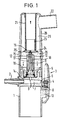
- connection piece 2 for the pressurized gas line and the feeler lever 3 arranged opposite the connection piece 2 with a sealing insert 4 for closing the outlet opening 6 in the supply channel 7.
- the Tastheoel 3 can be used by the user in a simple manner from its inoperative position shown in FIG. 1 by overcoming the force of the spring 8 with the front part of the feeler lever 3 in contact with the surface of the nebulizer, the sealing insert 4 laying on the outlet opening 6 and thus shuts off the supply line K anal for the pressure gas and this bypasses the transverse bore 9 into the central pressure gas line 11 of the nozzle head 10.
- the push button 3 serves to interrupt the flow of compressed gas in the exhalation phases of the user, in which no aerosol is to be generated.
- the feeler lever is pivoted into its operating position by means of a box-shaped slider which overlaps it in its rear area, in that the slider is guided into the pin 13 by means of two provided in its side walls Elongated holes are pushed over the feeler lever 3.
- the likewise cylindrical container 15 for receiving the material 16 to be atomized is screwed in a known manner with the interposition of an elastic sealing ring 14.
- the container 15 is also the atomizing nozzle, consisting of the nozzle head 10 with the central compressed gas line 11 and the two side suction channels 17 and 18 for the material 16 to be atomized and the gas flow control 19.
- the central compressed gas line 11 tapers towards the upper end of the nozzle head and ends in the narrow nozzle bore 12, which opens out from the nozzle head below the gas flow control 19.
- the cylindrical nebulizer hood 20 is screwed onto the container 15.
- the nebulizer hood 20 contains a coaxial supply air chimney 21, which extends into the interior of the nebulizer up to just above the gas flow control 19.
- the mist outlet connection 22 is attached, to which a mouthpiece (not shown in the drawing) can be attached.
- the supply air chimney 21 carries at its lower end a cylindrical insert 23 with a baffle screen 24. At least some of the larger particles of the aerosol generated on the inclined surfaces of the gas flow control 19 are broken up and crushed.
- This intrathoracic portion is, for example, approximately 40% in the comparison test mentioned for the pari-therapy device, while surprisingly it is almost doubled when the nebulizer device according to the invention is used.
- the effective area is the inner shell of the Verneblerhaube 20 as Prallfläcne for the A erosolfäcner 25, 26 limited, the more intensive interaction-acres the inner surface of the baffle screen 24, and the compartments but does not compensate for this loss only, but seems to make out the desired effect.
- the impact screen 24 limits the annular gap between the outer wall of the supply air chimney 21 and the inner wall of the nebulizer hood 20; As a result, droplets which are too large are already deposited in this area on the edge of the baffle screen 24 and ah on the inner wall of the nebulizer hood and run back into the container 15 to the atomizing material 16.
- the coaxial chimney 21 instead of the cylindrical insert 23 with impact screen 24, the coaxial chimney 21 also has a corresponding impact at its end can be 24 days old.
- the two-part nature has the advantage that the two parts can be pushed apart in a simple manner when cleaning the device and the chimney 21 can thus be removed from the nebulizer hood 2U in a simple manner.
- the baffle 24 extends at an angle of about 120 ° from the surface of the chimney 21 to the extent that its outer edge between about two thirds of the free circular ring diameter from the inside out the coaxial chimney 21 and the nebulizer 2U come to rest.
- FIG. 3 A second embodiment of the invention is shown in FIG. 3. This is the enlarged view of an atomizer head, in which the baffle 44 according to the invention is realized in a similar manner to that in the exemplary embodiment according to FIGS. 1 and 2; the screen is not conical in cross-section, but parabolic.
- the atomizer shown is part of a connectable to a source of pressurized gas handset for Innalations, wherein the associated the atomizer K opf 3U enclosing handle is not shown.
- the atomizer head 30 is connected to a pressure gas source via the connecting piece 31.
- the compressed gas supply can be regulated by a separately attachable break valve, not shown in the drawing.
- the atomizing material 16 is sucked upward from the container 36 by the adjacent suction channels 34, 35 and crushed at the airflow control 37.
- the upper part of the compressed gas line also has a tapered, narrow nozzle bore for accelerating the compressed gas. Because of the high exit velocity, an underpressure occurs in this area, which ensures that supply air is drawn in via the coaxial chimney 38 in the same way as in the first embodiment, so that the desired amount of air is set in the aerosol outlet nozzle 39.
- the operation of the atomizer according to FIG. 3 is similar to that according to FIGS. 1 and 2: after the formation of the aerosol on the gas flow control 37, some of the aerosol particles of the compartments 27, 28 reach the inside of the impact screen 44, which is at the end of the cylindrical insert 43 is formed and is thereby crushed even further. Larger particles drip off the edge 40 of the impact screen 44 and thus return to the material 16 to be atomized in the container 36.
- the effect of the relatively honed ring chimney in the nebulizer hood 20 around the coaxial chimney 21 in the first embodiment is compensated for in the variant according to FIG. 3 by a kind of labyrinthine guidance of the aerosol flow as far as the outlet nozzle 39, which in addition to the edge 40 already mentioned has a further one Edge 41 of an insert 42 arranged in container 36 must flow around. Further larger particles are filtered out of the aerosol stream and run back along the inner wall of the insert 42 into the container 36. The aerosol filtered in this way from particles that are too large leaves the atomizer head through the outlet connection 39 and contains also a high proportion of respirable aerosol.
- the spherical configuration according to FIG. 3 naturally has the advantage of a low construction color compared to that shown in FIG. 1.
- the atomizer head can also be easily accommodated in one movement, as already mentioned at the beginning.
- the insert 42 is formed by an axially symmetrical component with a cylindrical edge flange 46 and a sicn frustoconical wall part 47 tapering upwards into the nebulizer chamber, the edge of which is drawn inwards so far as to form the second edge 41 that in the assembled state only a relatively narrow one Annular space remains between the outer wall of the chimney 38 and the edge 41, so that larger droplets are cut off in the area of the edge 41 and run back into the container 36 in the manner described.
- the insert 42 expediently has an outwardly projecting lip 48 between the edge flange 46 and the wall part 47. This lip serves to fix the insert 42 to a correspondingly designed edge of the container 36, so that when the atomizer device, i.e. when the hood 45 is placed on the container 36, the insert 42 is automatically clamped between these two parts and fixed in this position.
- the outlet ports 22 and 39 for the aerosol are designed so that different attachments for special inhalations can be attached.
- a suitable sprayable plastic of known type is used as the material for all parts of the nebulizer.
Abstract
Description
Die Erfindung betrifft eine Zerstäubervorrichtung nach dem Oberbegriff von Patentanspruch 1.The invention relates to an atomizer device according to the preamble of
Eine derartige Zerstäubervorrichtung ist in der DE-PS 1 147 355 beschrieben. Mit der vorbekannten Zerstäuberdüse erreicht man eine zufriedenstellende Zerstäubung auch von Flüssigkeiten bis zu einer Viskosität von etwa 70 cp bei einem Gasdruck von nur etwa 0,6 bar.Such an atomizing device is described in DE-PS 1 147 355. With the known atomizing nozzle, a satisfactory atomization of liquids up to a viscosity of about 70 cp is achieved with a gas pressure of only about 0.6 bar.
In dem Bestreben, immer leistungsfähigere Inhaliergeräte zu schaffen, die eine verbesserte Zerstäuberwirkung bei gleichem Gasdruck zeigen, hat man Versuche auch mit gegenüber der vorbekannten Düse abgewandelten Düsen vorgenommen und durch moderne klinische Methoden den intrathorakalen (lungengängigen) Aerosolanteil gemessen. Dabei handelt es sich um denjenigen Anteil, dessen Tröpfchengröße in einem Spektrum von etwa 0,5 bis 5/u Durchmesser liegt und der bis in die feinsten Verästelungen der Lunge beim Einatmen gelangt.In an effort to create ever more powerful inhalers that show an improved atomizing effect at the same gas pressure, tests have also been carried out with nozzles modified compared to the previously known nozzle and the intrathoracic (respiratory) aerosol content has been measured using modern clinical methods. This is the portion whose droplet size lies in a spectrum of about 0.5 to 5 / u diameter and which reaches the finest branches of the lungs when inhaled.
Ein derartiges Inhaliergerät ist in dem DE-GM 8 302 105 beschrieben. Bei diesem Gerät ist die Verneblerdüse mit einem axialgerichteten mittigen Auslaß ausgebildet und diesem Auslaß ein Pralldorn mit einer Prallstirnfläche gegenübergestellt, an der das Aerosol erzeugt wird. Zusätzlich kann bei dieser Ausführung um den Pralldorn herum auch ein koaxialer Prallhelm angeordnet sein, in dem in Höhe der Verneblerdüse fensterartige Auslaßöffnungen für das an der Prallfläche erzeugte Aerosol vorgesehen sind. Diese Fenster erstrecken sich über etwa die Hälfte oder mehr des Prallhelnumfangs. Diese Vorrichtung weist keinen zentralen Zuluftkamin auf. Die in der Einatemphase notwendige Zuluft wirdSuch an inhaler is described in DE-GM 8 302 105. In this device, the nebulizer nozzle is designed with an axially directed central outlet and this outlet is juxtaposed with a baffle mandrel with a baffle face on which the aerosol is generated. In addition, in this embodiment, a coaxial impact helmet can also be arranged around the impact mandrel, in which window-like outlet openings for the aerosol generated on the impact surface are provided at the level of the nebulizer nozzle. These windows span about half or more of the perimeter of the baffle. This device has no central supply air chimney. The supply air necessary in the inhalation phase becomes
bei einem nach diesem DE-GM gefertigten Inhaliergerät durch Schlitze am Rand in dem Verbindungsflansch zwischen dem Behälter und der Verneblerhaube zugeführt. An dem Prallhelm werden größere und mittlere Flüssigkeitströpfchen aufgefangen und aus dem Nebel ausgesondert. Eine Erhöhung des Anteils lungengängiger Aerosolteilchen erfolgt dabei nicht, da der Aerosolstrom von der zentralen waagerechten Prallfläche im wesentlichen waagerecht nach außen geleitet wird und hierbei allenfalls durch zusätzliche Flüssigkeitströpfchen abgelenkt wird, die aus dem sich konisch erweiternden Ausgang der Verneblerdüse austreten und die Prallfäche nicht mehr treffen.in an inhaler manufactured according to this DE-GM through slots on the edge in the connecting flange between the container and the nebulizer hood. Large and medium-sized liquid droplets are collected on the impact helmet and separated out of the mist. There is no increase in the proportion of respirable aerosol particles, since the aerosol flow is directed essentially horizontally outwards from the central horizontal baffle and is thereby deflected by additional liquid droplets that emerge from the conically widening outlet of the nebulizer nozzle and no longer hit the baffle .
Es ist die Aufgabe der Erfindung, eine Zerstäubervorrichtung der vorgenannten Art so zu verbesesrn, daß bei vorgegebenem Gasdruck eine möglichst große Aerosolmenge und daraus wieder ein möglichst hoher Anteil von intrathorakalen (lungengängigen) Aerosolpartikeln, d.h. von Teilchen in einer Größe zwischen etwa 0,5 und 5,5 p Durchmesser erzeugt wird.It is the object of the invention to improve an atomizing device of the aforementioned type in such a way that at a given gas pressure the greatest possible amount of aerosol and, as a result, the greatest possible proportion of intrathoracic (respirable) aerosol particles, i.e. of particles between about 0.5 and 5.5 p in diameter.
Dieses Ziel wird gemäß der Erfindung mit einer Zerstäubervorrichtung erreicht, die sich durch die Merkmale des Kennzeichens von Patentanspruch 1 auszeichnet. Durch die Anbringung eines zylindrischen Einsatzes mit einem sich schräg nach außen und abwärts in den Verneblerraum erstreckenden Prallschirm am unteren Ende des koaxialen Zuluftkamins werden die mit hoher Energie auf die innere Mantelfläche des Prallschirms auftreffenden Aerosolteilchen nicht nur umgelenkt oder in Tropfenform abgeschieden, sondern weiter zerkleinert, so daß der Anteil der lungengängigen Aerosolfraktion ganz erheblich gesteigert wird.This object is achieved according to the invention with an atomizer device which is characterized by the features of the characterizing part of
Vorzugsweise erstreckt sich der Prallschirm kegelig nach außen, wobei er einen Winkel von etwa 120° gegenüber der Mantelfläche einnehmen kann. Er kann jedoch auch glockenförmig, kugelig oder parabolisch geformt sein, wobei im letzteren Fall die untere Mantelfläche des Prallschirmes noch unter einem kleinen Winkel gegenüber der Mantelfläche des Zuluftkamins nach außen verläuft. Dabei erstreckt sich der Außenrand des Sdhirmsgegen die Innenwandung der Verneblerhaube und reduziert so den Ringraum um den Zuluftkamin; bei einem Ausführungsbeispiel auf etwa ein Drittel des freien Durchlaßquerschnittes. Die an den schrägen Prallflächen des Gasstromsteuers erzeugten und schräg nach oben abgelenkten Aerosolpartikel gelangen so in den Bereich der inneren Mantelfläche des Schirmes, wo größere Partikel durch den Aufprall nochmals zerkleinert werden. Dadurch wird der Gesamtanteil der lungengängigen Aerosolfraktion im gewünschten Spektrum zwischen 0,5 bis 5,5 u vergrößert. Durch die Unterkante des Prallschirms erfolgt zusätzlich auch eine Ausfilterung und Abscheidung von zu großen Teilchen. Gelangen zu große Teilchen in den Ringraum um den Zuluftkamin, so werden sie dort bei der üblicherweise senkrechten Handhabung des Zerstäubers infolge ihrer Schwerkraft ausgeschieden, zum Zerstäubungsgut zurückgeleitet und gelangen nicht aus der Verneblerhaube in den Nebelaustrittsstutzen.Preferably, the baffle extends conically outwards, making an angle of approximately 120 ° with respect to that Can take up the outer surface. However, it can also be bell-shaped, spherical or parabolic in shape, in the latter case the lower surface of the baffle still running outward at a small angle with respect to the surface of the supply air chimney. The outer edge of the screen extends against the inner wall of the nebulizer hood and thus reduces the annular space around the supply air chimney; in one embodiment to about a third of the free passage cross section. The aerosol particles generated on the inclined baffles of the gas flow control and deflected diagonally upward thus reach the area of the inner lateral surface of the screen, where larger particles are further crushed by the impact. This increases the total proportion of the respirable aerosol fraction in the desired spectrum between 0.5 and 5.5 u. The lower edge of the impact screen also filters out and separates oversized particles. If too large particles get into the annular space around the supply air chimney, they are excreted there due to their gravity during the usually vertical handling of the atomizer, returned to the atomizing material and do not get out of the nebulizer hood into the mist outlet connection.
Bei einer Weiterbildung der Zerstäubervorrichtung kann die Gesamtbauhöhe der Einrichtung zur Erzielung eines kompakten Verneblers dadurch reduziert werden, daß der Aerosolstrom in der Verneblerhaube um den Zuluftkamin herum über eine Art Labyrinth mit mindestens einer zusätzlichen Abrißkante herumgeleitet wird, wodurch zu große Tröpfchen nicht nur infolge der Schwerkraft, sondern auch durch ihren Kontakt an einer derartigen Schikane infolge der Umleitung abgeschieden und dem Sammelbehälter wieder zugeführt werden.In a further development of the atomizer device, the overall height of the device for achieving a compact nebulizer can be reduced by the fact that the aerosol flow in the nebulizer hood is directed around the supply air chimney over a kind of labyrinth with at least one additional tear-off edge, as a result of which large droplets are not only due to gravity , but also separated by their contact at such a chicane as a result of the diversion and returned to the collection container.
Bei axialsymmetrischer Bauweise des Zerstäubers kann in einfacher Weise ein zusätzlicher Einsatz zur Umlenkung des Aerosolstromes zwischen Behälter und Haube vorgesehen sein, wodurch man die angestrebte Verringerung der Bauhöhe des koaxialen Zuluftkamins erreicht. Der zusätzliche Einsatz kann von einem Bauteil mit einem zylindrischen Randflansch und einem sich nach oben in den Verneblerraum etwa kegelstumpfförmig verjüngenden Wandteil gebildet sein, dessen Innenrand als Abrißkante ausgebildet ist. Dieser Einsatz kann durch entsprechende Gestaltung der miteinander in Eingriff stehenden Ränder des Behälters und der Haube zwischen diesen gehalten sein.With an axially symmetrical design of the atomizer can in a an additional insert for deflecting the aerosol flow between the container and the hood can be provided, thereby achieving the desired reduction in the overall height of the coaxial supply air chimney. The additional insert can be formed by a component with a cylindrical edge flange and a wall part that tapers approximately frustoconically into the nebulizer chamber, the inner edge of which is designed as a tear-off edge. This insert can be held between them by appropriate design of the mutually engaging edges of the container and the hood.
Die beiden bei dieser Ausführungsform geschaffenen Abrißkanten für die Ausfilterung von zu großen Aerosoltröpfchen und zwar die Außenkante des sich nach unten erstreckenden Prallschirms und die Innenkante des genannten Einsatzes erlauben eine erhebliche Reduzierung der Bauhöhe der erfindungsgemäßen Zerstäubervorrichtung und ermöglichen so eine nahezu kugelige Gestaltung, die beispielsweise den Einsatz eines so geschaffenen Zerstäuberkopfes in einen angepassten Handgriff ermöglicht.The two tear-off edges created in this embodiment for filtering out too large aerosol droplets, namely the outer edge of the downwardly extending baffle and the inner edge of the insert mentioned, allow a considerable reduction in the overall height of the atomizing device according to the invention and thus enable an almost spherical design, for example the Use of an atomizer head created in this way in an adapted handle.
Weitere Einzelheiten der Erfindung ergeben sich aus der Beschreibung zweier in der Zeichnung dargestellter Ausführungsbeispiele.
Figur 1 ist ein Mittellängsschnitt durch eine erste Ausführungsform der Zerstäubervorrichtung;- Figur 2 zeigt einen vergrößerten Ausschnitt des mittleren Teils der Vorrichtung von Fig. 1;
- Figur 3 ist ein Mittellängsschnitt durch eine zweite Ausführungsform der Zerstäubervorrichtung.
- Figure 1 is a central longitudinal section through a first embodiment of the atomizer device;
- Figure 2 shows an enlarged section of the central part of the device of Fig. 1;
- Figure 3 is a central longitudinal section through a second embodiment of the atomizer device.
Die in Fig. 1 gezeigte Zerstäubungsvorrichtung besteht im wesentlichen aus dem zylindrischen Verneblerunterteil 1 mit Anschlußstutzen 2 für die Druckgasleitung und dem gegenüber dem Anschlußstutzen 2 angeordneten Tasthebel 3 mit einem Dichtungseinsatz 4 zum Verschließen der Auslaßöffnung 6 im Zuleitungskanal 7.1 consists essentially of the cylindrical nebulizer
Der Tastheoel 3 kann vom Benutzer in einfacher Weise aus seiner in Fig. 1 gezeigten Außerbetriebsstellung unter Überwindung der Kraft der Feder 8 mit dem Vorderteil des Tasthebels 3 in Anlage zur Oberfläche des Verneblers gebracnt werden, wobei der Dichteinsatz 4 sich auf die Auslaßöffnung 6 legt und so den Zulei- tungsKanal für das DrucKgas absperrt und dieses durcn die Querbohrung 9 in die zentrale Druckgasleitung 11 des DüsenKopfes 10 umleitet. Der Tastnepel 3 dient zur Unterbrechung des Druckgasstromes in den Ausatemphasen des Benutzers, in denen Kein Aerosol erzeugt werden soll. Er kann jedoch auch für den Dauerbetrieb des Innalationsgerätes in Anlage am Gehäuse fixiert werden, indem der Tasthebel mittels eines ihn in seinem hinteren Bereich übergreifenden kastenförmigen Schiebers dadurch in seine Betriebsstellung verschwenkt wird, daß der Schieber mittels zweier in seinen Seitenwandungen vorgesehener in den Zapfen 13 geführter Langlöcher über den Tasthebel 3 geschoben wird.The Tastheoel 3 can be used by the user in a simple manner from its inoperative position shown in FIG. 1 by overcoming the force of the
In das Verneblerunterteil 1 ist in bekannter Weise unter Zwischenschaltung eines elastischen Dichtungsringes 14 der gleichfalls zylindriscne Behälter 15 zur Aufnahme des zu zerstäubenden Gutes 16 eingeschraubt. Im Behälter 15 ist auch die Zerstäuberdüse, bestehend aus dem Düsenkopf 10 mit der zentralen Druckgasleitung 11 und den beiden seitlicnen Ansaugkanälen 17 und 18 für das zu zerstäubende Gut 16 und dem Gasstromsteuer 19 untergeoracnt. Die zentrale Druckgasleitung 11 verjüngt sich gegen das obere Ende des Düsenkopfes zu und endet in der schmalen Düsenbohrung 12, welche unterhalb des Gasstromsteuers 19 aus dem Düsenkopf ausmündet.In the nebulizer
Auf dem Behälter 15 ist die zylindrische Verneblerhaube 20 aufgeschraubt. Die Verneblerhaube 20 enthält einen koaxialen Zuluftkamin 21, der sich bis dicht über das Gasstromsteuer 19 in den Innenraum des Verneblers hineinerstreckt. Im oberen Teil ist an die Verneblerhaube 20 der Nebelaustrittstutzen 22 angesetzt, an den ein in der Zeichnung nicht dargestelltes Mundstück ansetzbar ist.The
Der Zuluftkamin 21 trägt an seinem unteren Ende einen zylindrischen Einsatz 23 mit einem Prallschirm 24. An diesem wird zumindest ein Teil der größeren Partikel des an den Scnrägflächen des Gasstromsteuers 19 erzeugten Aerosols zersplittert und so weiter zerkleinert.The
Bei der vorbekannten Konstruktion gemäß DE-PS 1 147 355 war man davon ausgegangen, daß bei entsprechender Dimensionierung des Durchmessers der Verneblerhaube bei vorgegebenem Überdruck der Druckgasquelle die Innenwandung der Verneblerhaube als Prall- und auch Sammelfläche für zu große Tropfen des Aerosolstromes ausreicht. Entsprechende Messungen der lungengängigen Aerosolstrommenge mit radioaktiv markiertem zu zerstäubenden Gut haben ergeben, daß in erwünschter Weise eine relativ große Menge Aerosol vom Benutzer in der Zeiteinheit eingeatmet wird und daß ein erheblicher Anteil davon auch intrathorakal resorbiert wird (vgl. Zeitscnrift der Stiftung Warentest 1983, Nr. 6, S. 32 - 37).In the previously known construction according to DE-PS 1 147 355, it was assumed that with appropriate dimensioning of the diameter of the nebulizer hood at a given excess pressure of the pressurized gas source, the inner wall of the nebulizer hood would be sufficient as a baffle and collecting surface for drops of the aerosol stream that were too large. Corresponding measurements of the amount of aerosol current that can enter the lungs with radioactively labeled material to be atomized have shown that, in the desired manner, se a relatively large amount of aerosol is inhaled by the user in the unit of time and that a significant proportion of it is also absorbed intrathoracically (see Zeitznschrift of Stiftung Warentest 1983, No. 6, pp. 32-37).
Dieser intrathorakale Anteil beträgt in dem genannten Vergleichstest für das Pari-Therapiegerät beispielsweise ca. 40%, während er bei Einsatz der erfindungsgemäßen Zerstäubervorrichtung erstaunlicherweise nahezu verdoppelt ist.This intrathoracic portion is, for example, approximately 40% in the comparison test mentioned for the pari-therapy device, while surprisingly it is almost doubled when the nebulizer device according to the invention is used.
Anhand von Fig. 2, die einen vergrößerten Querschnitt des eigentlichen Zerstäuberteils mit dem Prallschrim 24 darstellt, wird die WirKungsweise des neuen Zerstäubers im folgenden erläutert:
- An den in Fig. 2 nicht dargestellten Anschlußstutzen 2 wird eine Druckgasquelle, z.B. ein Kompressor, der den erforderlichen Überdruck erzeugt (ca. 0,6 bar) angeschlossen. Das Druckgas steigt durch die
zentrale Druckgasleitung 11 und dieDüsenbonrung 12 bis zur Austrittsöffnung im Düsenkopf 10. Durch die Verjüngung der zentralen DrucKgasleitung im ooeren Bereicn desDüsenkopfes 10 erhält die Druckluft eine hohe AustrittsgescnwindigKeit. Beim Austritt der Luft aus derDüsenbohrung 12 wird durch diebenachbarten Ansaugkanäle Zerstäubangsgut 16 aus dem unteren Teil desBehälters 15 nach oben gesaugt und an den scnräggestellten Prallflächen desGasstromsteuers 19 zerkleinert und verteilt. Der übliche Keilwinkel desGasstromsteuers 19 beträgt etwa 120°, so daß sich beiderseitig zwischen der oberen Ebene desDüsenkopfes 10 und der Verlängerung der Keilflächen des
- A compressed gas source, for example a compressor, which generates the required excess pressure (approx. 0.6 bar) is connected to the connecting piece 2, which is not shown in FIG. 2. The compressed gas rises through the central
compressed gas line 11 and thenozzle 12 to the outlet opening in thenozzle head 10. The tapering of the central pressure gas line in the upper region of thenozzle head 10 gives the compressed air a high outlet speed. When the air emerges from the nozzle bore 12, the atomizingmaterial 16 is sucked up from the lower part of thecontainer 15 through theadjacent suction channels gas flow control 19. The usual wedge angle of thegas flow control 19 is approximately 120 °, so that there is mutual between the upper level of thenozzle head 10 and the extension of the wedge surfaces of the
Durcn die Anordnung des zusätzlichen Prallschirmes 24 wird die wirksame Fläche des Innenmantels der Verneblerhaube 20 als Prallfläcne für die Aerosolfäcner 25, 26 zwar begrenzt, die intensivere Wechselwirkung zwiscnen der Innenfläche des Prallschirms 24 und den Fächern kompensiert diesen Verlust aber nicht nur, sondern scheint hier gerade den gewünschten EffeKt auszumachen.Durcn the arrangement of the
Der Prallscnirm 24 bewirkt eine Begrenzung des Ringspaltes zwischen der Außenwandung des Zuluftkamins 21 und der Innenwandung der Verneblernaube 20; dadurch werden bereits in diesem Bereich zu große Tröpfchen an der Kante des Prallschirmes 24 und ah der Innenwandung der Verneblerhaube abgeschieden und laufen in den Benälter 15 zum Zerstäubungsgut 16 zurück.The
Es versteht sich, daß anstelle des zylindrischen Einsatzes 23 mit Prallscnirm 24 auch der koaxiale Kamin 21 an seinem Ende mit einem entsprechenden Prallscnirm 24 versenen sein Kann. Die Zweiteiligkeit nat jedoch den Vorteil, daß die beiden Teile beim Reinigen des Gerätes in einfacher Weise auseinandergeschoben werden können und sich so der Kamin 21 in einfacner Weise aus der Verneblernaube 2U nach oben entfernen läßt.It is understood that instead of the
Bei der Ausführungsform des Verinelers nach den Figuren 1 und 2 erstreckt sich der Prallschirm 24 unter einem Winkel von etwa 120° von der Mantelfäche des Kamins 21 nach außen und zwar soweit, daß sein Außenrand bei etwa zwei Drittel des freien Kreisringdurcnmessers von innen nach außen zwischen dem koaxialen Kamin 21 und der Verneblernaube 2U zu liegen Kommt.In the embodiment of the Verineler according to Figures 1 and 2, the
Eine zweite Ausführungsform der Erfindung ist in Fig. 3 dargestellt. Dabei handelt es sich um die vergrößerte Ansicht eines Zerstäuberkopfes, bei welchem der erfindungsgemäße Prallschirm 44 in ähnlicher Weise wie bei dem Ausführungspeispiel nacn den Figuren 1 und 2 realisiert ist; der Schirm ist im Querschnitt hier jedocn nicht kegelig, sondern parabolisch ausgebildet. Der gezeigte Zerstäuberkopf ist Teil eines an eine DrucKgasquelle anschliessbaren Handgerätes für Innalationszwecke, wobei der zugehörige den ZerstäuberKopf 3U umschliessende Handgriff nicht dargestellt ist. Der Zerstäuberkopf 30 wird über den Anschlußstutzen 31 an eine DrucKgasquelle angeschlossen. Die Druckgaszufuhr kann durch ein in der Zeichnung nicht dargestelltes separat aufbringbares Unterbrecherventil geregelt werden. Beim Austritt des Druckgases aus der zentralen Druckgasleitullg 32 im Düsenkopf 33 wird von den benachbarten Ansaugkanälen 34, 35 das Zerstäubungsgut 16 aus dem Benälter 36 nach oben gesaugt und am Luftstromsteuer 37 zerkleinert. Die Druckgasleitung weist in ihrem oberen Teil gleichfalls eine verjüngte scnmale Düsenbohrung zur Beschleunigung des Druckgases auf. Aufgrund der hohen Austrittsgeschwindigkeit entstent in diesem Bereich ein UnterdrucK, der dafür sorgt, daß in gleicher Weise wie beim ersten Ausführungsbeispiel über den Koaxialen Kamin 38 Zuluft angesaugt wird, so daß sich im Aerosolaustrittsstutzen 39 die gewünschte Luftmenge einstellt.A second embodiment of the invention is shown in FIG. 3. This is the enlarged view of an atomizer head, in which the
Die WirKungsweise des Zerstäubers gemäß Fig. 3 ist ähnlich wie die gemäß den Figuren 1 und 2: nach der Ausbildung des Aerosols am Gasstromsteuer 37 gelangt ein Teil der Aerosolpartikel der Fächer 27, 28 an die Innenseite des Prallscnirmes 44, der am Ende des zylindrischen Einsatzes 43 ausgebildet ist und wird dadurch noch weiter zerkleinert. Größere Teilchen tropfen von der Kante 40 des Prallschirms 44 ab und gelangen so wieder zum Zerstäuoungsgut 16 im Behälter 36 zurück.The operation of the atomizer according to FIG. 3 is similar to that according to FIGS. 1 and 2: after the formation of the aerosol on the
Die Wirkung des relativ honen Ringkamins in der Verneblerhaube 20 um den koaxialen Kamin 21 bei der ersten Ausführungsform wird bei der Variante gemäß Fig. 3 kompensiert durch eine Art Labyrinthführung des Aerosolstromes bis zum Austrittsstutzen 39, wobei dieser neben der bereits genannten Kante 40 noch eine weitere Kante 41 eines im Benälter 36 angeordneten Einsatzes 42 umströmen muß. Dabei werden weitere größere PartiKel aus dem Aerosolstrom ausgetiltert, die an der Innenwandung des Einsatzes 42 entlang wieder in den Benälter 36 zurücKlaufen. Das so von zu großen Partikeln gefilterte Aerosol verläßt den Zerstäuberkopf durcn den Austrittsstutzen 39 und enthält gleichfalls einen hohen Anteil von lungengängigem Aerosol.The effect of the relatively honed ring chimney in the
Die kugelige Konfiguration gemäß Fig. 3 nat gegenüber dem in Fig. 1 gezeigten den Vorteil einer geringen Baunöne. Der ZerstäuberKopf läßt sicn daner in einfacher Weise, wie bereits eingangs erwähnt, in einem Handgriff unterbringen.The spherical configuration according to FIG. 3 naturally has the advantage of a low construction color compared to that shown in FIG. 1. The atomizer head can also be easily accommodated in one movement, as already mentioned at the beginning.
Der Einsatz 42 ist von einem axialsymmetrischen Bauteil mit einem zylindrischen Randflansch 46 und einem sicn nach oben in den Verneblerraum kegelstumpfförmig verjüngenden Wandteil 47 gebildet, dessen Rand unter Ausbildung der zweiten Kante 41 soweit nach innen gezogen ist, daß im zusammengebauten Zustand nur noch ein relativ schmaler Ringraum zwischen der Außenwandung des Kamins 38 und der Kante 41 verbleibt, so daß größere Tröpfchen im Bereich der Kante 41 abgescnieden werden und in der beschriebenen Weise wieder in den Benälter 36 zurücklaufen. Dabei besitzt der Einsatz 42 zweckmäßigerweise eine nach außen vorspringende Lippe 48 zwischen dem Randflansch 46 und dem Wandteil 47. Diese Lippe dient zur Fixierung des Einsatzes 42 an einem entsprechend ausgebildeten Rand des Behälters 36, so daß beim Zusammenbau der Zerstäubervorrichtung, d.h. beim Aufsetzen der Haube 45 auf den Behälter 36 der Einsatz 42 automatisch zwischen diese beiden Teile geKlemmt und in dieser Lage fixiert ist.The
Die Austrittsstutzen 22 bzw. 39 für das Aerosol sind so gestaltet, daß verschiedene Aufsätze für spezielle Inhalationen aufsteckbar sind.The
Als Material für sämtliche Teile des Verneblers kommt ein geeigneter spritzfähiger Kunststoff bekannter Art zum Einsatz.A suitable sprayable plastic of known type is used as the material for all parts of the nebulizer.
Claims (10)
Priority Applications (3)
| Application Number | Priority Date | Filing Date | Title |
|---|---|---|---|
| DE8484109456T DE3470380D1 (en) | 1984-08-09 | 1984-08-09 | Nebulizer |
| AT84109456T ATE33447T1 (en) | 1984-08-09 | 1984-08-09 | ATOMIZER. |
| EP84109456A EP0170715B1 (en) | 1984-08-09 | 1984-08-09 | Nebulizer |
Applications Claiming Priority (1)
| Application Number | Priority Date | Filing Date | Title |
|---|---|---|---|
| EP84109456A EP0170715B1 (en) | 1984-08-09 | 1984-08-09 | Nebulizer |
Publications (2)
| Publication Number | Publication Date |
|---|---|
| EP0170715A1 true EP0170715A1 (en) | 1986-02-12 |
| EP0170715B1 EP0170715B1 (en) | 1988-04-13 |
Family
ID=8192099
Family Applications (1)
| Application Number | Title | Priority Date | Filing Date |
|---|---|---|---|
| EP84109456A Expired EP0170715B1 (en) | 1984-08-09 | 1984-08-09 | Nebulizer |
Country Status (3)
| Country | Link |
|---|---|
| EP (1) | EP0170715B1 (en) |
| AT (1) | ATE33447T1 (en) |
| DE (1) | DE3470380D1 (en) |
Cited By (28)
| Publication number | Priority date | Publication date | Assignee | Title |
|---|---|---|---|---|
| EP0257956A2 (en) * | 1986-08-19 | 1988-03-02 | Genentech, Inc. | Device and dispersion for intrapulmonary delivery of polypeptide growth factors and cytokines |
| EP0471323A1 (en) * | 1990-08-13 | 1992-02-19 | PAUL RITZAU PARI-WERK GmbH | Atomizer for liquid medicaments |
| DE4322111A1 (en) * | 1993-07-02 | 1995-01-19 | Ritzau Pari Werk Gmbh Paul | Inhalation atomiser with container insert for the atomisation material |
| EP0653218A1 (en) * | 1993-11-15 | 1995-05-17 | PAUL RITZAU PARI-WERK GmbH | Atomizer device |
| WO1995020988A1 (en) * | 1994-02-02 | 1995-08-10 | Baxter International Inc. | Continuous flow adaptor for a nebulizer |
| DE19520622A1 (en) * | 1995-06-06 | 1996-12-12 | Medanz Starnberg Gmbh | Device for atomizing fluids |
| WO1997018847A1 (en) * | 1995-11-07 | 1997-05-29 | Arborelius Lolita Med Firma Viasol Marketing | Nebuliser with vortex aerosol separator |
| EP0582124B1 (en) * | 1992-08-05 | 1997-06-11 | PAUL RITZAU PARI-WERK GmbH | Atomizer device with heating element |
| DE19600409A1 (en) * | 1996-01-08 | 1997-07-10 | Ritzau Pari Werk Gmbh Paul | Device for producing atomised spray for therapeutic use |
| US5687912A (en) * | 1994-11-11 | 1997-11-18 | Medic-Aid Limited | Atomizer |
| DE19902844C1 (en) * | 1999-01-20 | 1999-11-18 | Kendall Med Erzeugnisse Gmbh | Vaporizer for medicine, for inhalation purposes |
| DE19902845C1 (en) * | 1999-01-20 | 1999-11-25 | Kendall Med Erzeugnisse Gmbh | Medicament nebulizer for inhalation treatment |
| WO2001032246A1 (en) | 1999-11-05 | 2001-05-10 | Pari GmbH Spezialisten für effektive Inhalation | Inhalation nebuliser |
| WO2001056639A1 (en) | 2000-02-02 | 2001-08-09 | Pari GmbH Spezialisten für effektive Inhalation | Inhalation nebulizer |
| WO2003086081A2 (en) * | 2002-04-17 | 2003-10-23 | Flaem Nuova S.P.A. | Nebulizer chamber with vertical exit and anti-spill system |
| WO2003099360A1 (en) * | 2002-05-28 | 2003-12-04 | Medel S.P.A. | Nebuliser |
| EP1541186A1 (en) * | 2003-12-12 | 2005-06-15 | FLAEM NUOVA S.p.A. | Nebulizer device |
| DE102006017002B3 (en) * | 2006-04-11 | 2007-01-11 | Pari GmbH Spezialisten für effektive Inhalation | Nebulizer for inhalation therapy comprises compressed gas outlet openings arranged in a row to which are assigned fluid outlet openings forming a nozzle with the gas outlet openings |
| US7581718B1 (en) * | 2008-04-16 | 2009-09-01 | Hsiner Co., Ltd. | Atomizer |
| EP2272556A1 (en) | 2009-07-06 | 2011-01-12 | PARI GmbH Spezialisten für effektive Inhalation | Compressor for an aerosol therapy device |
| US20110253134A1 (en) * | 2010-04-16 | 2011-10-20 | Atlantean Corp. | Press-type medical aerosol generating device and pressing mechanism for the same |
| US20120174917A1 (en) * | 2011-01-12 | 2012-07-12 | Atlantean Corp. | Press-type medical nebulizer and pressing means thereof |
| CN103100134A (en) * | 2011-11-15 | 2013-05-15 | 德尔格医疗有限责任公司 | Nebulizer |
| WO2014067986A1 (en) | 2012-10-31 | 2014-05-08 | Galecto Biotech Ab | Galactoside inhibitor of galectin-3 and its use for treating pulmonary fibrosis |
| CN104971409A (en) * | 2015-06-25 | 2015-10-14 | 佛山可为医疗科技有限公司 | Aerosol infusion system |
| CN107497019A (en) * | 2017-06-23 | 2017-12-22 | 宁波贝斯美德医用器械有限公司 | Medical atomizer with improved structure |
| EP3459577A1 (en) * | 2017-09-22 | 2019-03-27 | Air Liquide Medical Systems S.p.A. | Nebulizer for aerosolizing a drug solution with an inner flared-out structure limiting the aerosol waste |
| CN111163821A (en) * | 2017-08-02 | 2020-05-15 | 泰利福医疗公司 | Medical vaporizer for rapid drug delivery |
Families Citing this family (2)
| Publication number | Priority date | Publication date | Assignee | Title |
|---|---|---|---|---|
| DE10022795B4 (en) * | 2000-05-10 | 2005-04-14 | Pari GmbH Spezialisten für effektive Inhalation | Breath-controlled inhalation therapy device |
| EP3225271B1 (en) | 2016-03-31 | 2019-09-04 | PARI GmbH Spezialisten für effektive Inhalation | Inhalation device with pressure-relief valve |
Citations (3)
| Publication number | Priority date | Publication date | Assignee | Title |
|---|---|---|---|---|
| GB269100A (en) * | 1926-12-10 | 1927-04-14 | Henri Curtat | Sprayer |
| FR1156698A (en) * | 1956-09-11 | 1958-05-20 | Method and apparatus for spraying liquids | |
| US3010910A (en) * | 1957-04-18 | 1961-11-28 | Gauchard Fernand | Method for producing true aerosols carrying mist of particles of microscopic structure |
-
1984
- 1984-08-09 AT AT84109456T patent/ATE33447T1/en not_active IP Right Cessation
- 1984-08-09 DE DE8484109456T patent/DE3470380D1/en not_active Expired
- 1984-08-09 EP EP84109456A patent/EP0170715B1/en not_active Expired
Patent Citations (3)
| Publication number | Priority date | Publication date | Assignee | Title |
|---|---|---|---|---|
| GB269100A (en) * | 1926-12-10 | 1927-04-14 | Henri Curtat | Sprayer |
| FR1156698A (en) * | 1956-09-11 | 1958-05-20 | Method and apparatus for spraying liquids | |
| US3010910A (en) * | 1957-04-18 | 1961-11-28 | Gauchard Fernand | Method for producing true aerosols carrying mist of particles of microscopic structure |
Cited By (49)
| Publication number | Priority date | Publication date | Assignee | Title |
|---|---|---|---|---|
| EP0257956A3 (en) * | 1986-08-19 | 1989-04-19 | Genentech, Inc. | Device and dispersion for intrapulmonary delivery of polypeptide growth factors and cytokines |
| EP0257956A2 (en) * | 1986-08-19 | 1988-03-02 | Genentech, Inc. | Device and dispersion for intrapulmonary delivery of polypeptide growth factors and cytokines |
| US6402733B1 (en) | 1986-08-19 | 2002-06-11 | Genentech, Inc. | Intrapulmonary delivery of polypeptide growth factors and cytokines |
| EP0471323A1 (en) * | 1990-08-13 | 1992-02-19 | PAUL RITZAU PARI-WERK GmbH | Atomizer for liquid medicaments |
| EP0582124B1 (en) * | 1992-08-05 | 1997-06-11 | PAUL RITZAU PARI-WERK GmbH | Atomizer device with heating element |
| DE4322111C2 (en) * | 1993-07-02 | 2001-05-10 | Pari Gmbh | Inhalation nebulizer |
| DE4322111A1 (en) * | 1993-07-02 | 1995-01-19 | Ritzau Pari Werk Gmbh Paul | Inhalation atomiser with container insert for the atomisation material |
| EP0694314A1 (en) * | 1993-07-02 | 1996-01-31 | PAUL RITZAU PARI-WERK GmbH | Inhalation nebuliser with detachable reservoir for the product to nebulise |
| EP0653218A1 (en) * | 1993-11-15 | 1995-05-17 | PAUL RITZAU PARI-WERK GmbH | Atomizer device |
| WO1995020988A1 (en) * | 1994-02-02 | 1995-08-10 | Baxter International Inc. | Continuous flow adaptor for a nebulizer |
| US5503139A (en) * | 1994-02-02 | 1996-04-02 | Mcmahon; Michael D. | Continuous flow adaptor for a nebulizer |
| US5687912A (en) * | 1994-11-11 | 1997-11-18 | Medic-Aid Limited | Atomizer |
| USRE40591E1 (en) * | 1994-11-11 | 2008-12-02 | Profile Respiratory Systems Limited | Atomizer |
| USRE42911E1 (en) | 1994-11-11 | 2011-11-15 | Ric Investments, Llc | Atomizer |
| DE19520622A1 (en) * | 1995-06-06 | 1996-12-12 | Medanz Starnberg Gmbh | Device for atomizing fluids |
| DE19520622C2 (en) * | 1995-06-06 | 2003-05-15 | Pari Gmbh | Device for atomizing fluids |
| WO1997018847A1 (en) * | 1995-11-07 | 1997-05-29 | Arborelius Lolita Med Firma Viasol Marketing | Nebuliser with vortex aerosol separator |
| GB2321605A (en) * | 1995-11-07 | 1998-08-05 | Arborelius Lolita | Nebuliser with vortex aerosol separator |
| DE19600409B4 (en) * | 1996-01-08 | 2005-02-24 | Pari GmbH Spezialisten für effektive Inhalation | Nebuliser device |
| DE19600409A1 (en) * | 1996-01-08 | 1997-07-10 | Ritzau Pari Werk Gmbh Paul | Device for producing atomised spray for therapeutic use |
| DE19902845C1 (en) * | 1999-01-20 | 1999-11-25 | Kendall Med Erzeugnisse Gmbh | Medicament nebulizer for inhalation treatment |
| DE19902844C1 (en) * | 1999-01-20 | 1999-11-18 | Kendall Med Erzeugnisse Gmbh | Vaporizer for medicine, for inhalation purposes |
| WO2001034232A1 (en) | 1999-11-05 | 2001-05-17 | Pari GmbH Spezialisten für effektive Inhalation | Inhalation nebulizer |
| WO2001032246A1 (en) | 1999-11-05 | 2001-05-10 | Pari GmbH Spezialisten für effektive Inhalation | Inhalation nebuliser |
| WO2001056639A1 (en) | 2000-02-02 | 2001-08-09 | Pari GmbH Spezialisten für effektive Inhalation | Inhalation nebulizer |
| US8596264B2 (en) | 2000-02-02 | 2013-12-03 | Pari GmbH Spezialisten für effektive Inhalation | Inhalation nebulizer |
| WO2003086081A3 (en) * | 2002-04-17 | 2004-03-25 | Flaem Nuova Spa | Nebulizer chamber with vertical exit and anti-spill system |
| WO2003086081A2 (en) * | 2002-04-17 | 2003-10-23 | Flaem Nuova S.P.A. | Nebulizer chamber with vertical exit and anti-spill system |
| WO2003099360A1 (en) * | 2002-05-28 | 2003-12-04 | Medel S.P.A. | Nebuliser |
| EP1541186A1 (en) * | 2003-12-12 | 2005-06-15 | FLAEM NUOVA S.p.A. | Nebulizer device |
| US8671933B2 (en) | 2006-04-11 | 2014-03-18 | Pari GmbH Spezialisten für effektive Inhalation | Inhalation therapy device with multiple nozzles |
| DE102006017002B3 (en) * | 2006-04-11 | 2007-01-11 | Pari GmbH Spezialisten für effektive Inhalation | Nebulizer for inhalation therapy comprises compressed gas outlet openings arranged in a row to which are assigned fluid outlet openings forming a nozzle with the gas outlet openings |
| US7581718B1 (en) * | 2008-04-16 | 2009-09-01 | Hsiner Co., Ltd. | Atomizer |
| EP2272556A1 (en) | 2009-07-06 | 2011-01-12 | PARI GmbH Spezialisten für effektive Inhalation | Compressor for an aerosol therapy device |
| US20110253134A1 (en) * | 2010-04-16 | 2011-10-20 | Atlantean Corp. | Press-type medical aerosol generating device and pressing mechanism for the same |
| US20120174917A1 (en) * | 2011-01-12 | 2012-07-12 | Atlantean Corp. | Press-type medical nebulizer and pressing means thereof |
| US8973572B2 (en) * | 2011-01-12 | 2015-03-10 | Atlantean Corp. | Press-type medical nebulizer and pressing means thereof |
| CN103100134B (en) * | 2011-11-15 | 2015-09-09 | 德尔格医疗有限责任公司 | Aerosol apparatus |
| CN103100134A (en) * | 2011-11-15 | 2013-05-15 | 德尔格医疗有限责任公司 | Nebulizer |
| WO2014067986A1 (en) | 2012-10-31 | 2014-05-08 | Galecto Biotech Ab | Galactoside inhibitor of galectin-3 and its use for treating pulmonary fibrosis |
| EP3278805A1 (en) | 2012-10-31 | 2018-02-07 | Galecto Biotech AB | Diagnosing pulmonary fibrosis |
| CN104971409A (en) * | 2015-06-25 | 2015-10-14 | 佛山可为医疗科技有限公司 | Aerosol infusion system |
| CN104971409B (en) * | 2015-06-25 | 2018-12-28 | 佛山可为医疗科技有限公司 | aerosol infusion system |
| CN107497019A (en) * | 2017-06-23 | 2017-12-22 | 宁波贝斯美德医用器械有限公司 | Medical atomizer with improved structure |
| CN107497019B (en) * | 2017-06-23 | 2020-08-21 | 宁波贝斯美德医用器械有限公司 | Medical atomizer with improved structure |
| CN111163821A (en) * | 2017-08-02 | 2020-05-15 | 泰利福医疗公司 | Medical vaporizer for rapid drug delivery |
| EP3661576A4 (en) * | 2017-08-02 | 2021-04-28 | Teleflex Medical Incorporated | Medical nebulizer for fast drug delivery |
| CN111163821B (en) * | 2017-08-02 | 2023-02-17 | 泰利福医疗公司 | Medical vaporizer for rapid drug delivery |
| EP3459577A1 (en) * | 2017-09-22 | 2019-03-27 | Air Liquide Medical Systems S.p.A. | Nebulizer for aerosolizing a drug solution with an inner flared-out structure limiting the aerosol waste |
Also Published As
| Publication number | Publication date |
|---|---|
| EP0170715B1 (en) | 1988-04-13 |
| ATE33447T1 (en) | 1988-04-15 |
| DE3470380D1 (en) | 1988-05-19 |
Similar Documents
| Publication | Publication Date | Title |
|---|---|---|
| EP0170715B1 (en) | Nebulizer | |
| DE3429389C1 (en) | Inhaler | |
| EP0540775B1 (en) | Atomiser particularly for inhalation therapy | |
| EP0653218B1 (en) | Atomizer device | |
| DE69420186T3 (en) | nebulizer | |
| EP0032391B1 (en) | Apparatus for atomizing liquid paint | |
| EP0682955B1 (en) | Device for drying and buffering aerosols | |
| DE1813993A1 (en) | Device for atomizing and distributing liquid or powdery substances | |
| EP0610350B1 (en) | Hand-held aerosol dispenser for therapeutic liquids | |
| EP0157250B1 (en) | Apparatus for the liquid treatment of seeds | |
| DE112012005500T5 (en) | Nebulizer and nebulizer kit | |
| DE19602628A1 (en) | Nebulizer | |
| EP0408786A1 (en) | Nozzle head | |
| EP0052284A2 (en) | Atomiser | |
| DE112012005482T5 (en) | Nebulizer and nebulizer kit | |
| DE202013002283U1 (en) | Sprayer nozzle for a sanitary water spout and sanitary outlet fitting with a water outlet | |
| DE1927207B2 (en) | COMPRESSION BOTTLE ATOMIZER | |
| DE3238149A1 (en) | Device for atomising, dispersing and mixing fluids | |
| DE19902844C1 (en) | Vaporizer for medicine, for inhalation purposes | |
| DE927920C (en) | Device and method for atomizing, distributing and mixing liquid or powdery substances | |
| CH641062A5 (en) | SPRAYER HEAD ON A PAINT SPRAY GUN. | |
| EP0471323B1 (en) | Atomizer for liquid medicaments | |
| DE2757522C2 (en) | Round or ring jet nozzle for generating and blasting a mist or aerosol for coating objects | |
| DE3429411A1 (en) | Atomiser nozzle | |
| DE1046264B (en) | Nebulizers for medical purposes |
Legal Events
| Date | Code | Title | Description |
|---|---|---|---|
| PUAI | Public reference made under article 153(3) epc to a published international application that has entered the european phase |
Free format text: ORIGINAL CODE: 0009012 |
|
| AK | Designated contracting states |
Designated state(s): AT BE CH DE FR GB IT LI LU NL SE |
|
| 17P | Request for examination filed |
Effective date: 19860428 |
|
| 17Q | First examination report despatched |
Effective date: 19870508 |
|
| GRAA | (expected) grant |
Free format text: ORIGINAL CODE: 0009210 |
|
| AK | Designated contracting states |
Kind code of ref document: B1 Designated state(s): AT BE CH DE FR GB IT LI LU NL SE |
|
| REF | Corresponds to: |
Ref document number: 33447 Country of ref document: AT Date of ref document: 19880415 Kind code of ref document: T |
|
| ITF | It: translation for a ep patent filed |
Owner name: BARZANO' E ZANARDO MILANO S.P.A. |
|
| RAP4 | Party data changed (patent owner data changed or rights of a patent transferred) |
Owner name: BRUGGER, STEPHAN Owner name: BRUGGER, INGE |
|
| GBT | Gb: translation of ep patent filed (gb section 77(6)(a)/1977) | ||
| REF | Corresponds to: |
Ref document number: 3470380 Country of ref document: DE Date of ref document: 19880519 |
|
| ET | Fr: translation filed | ||
| PLBE | No opposition filed within time limit |
Free format text: ORIGINAL CODE: 0009261 |
|
| STAA | Information on the status of an ep patent application or granted ep patent |
Free format text: STATUS: NO OPPOSITION FILED WITHIN TIME LIMIT |
|
| 26N | No opposition filed | ||
| ITTA | It: last paid annual fee | ||
| EPTA | Lu: last paid annual fee | ||
| REG | Reference to a national code |
Ref country code: GB Ref legal event code: 732E |
|
| EAL | Se: european patent in force in sweden |
Ref document number: 84109456.8 |
|
| PGFP | Annual fee paid to national office [announced via postgrant information from national office to epo] |
Ref country code: GB Payment date: 19970730 Year of fee payment: 14 |
|
| PG25 | Lapsed in a contracting state [announced via postgrant information from national office to epo] |
Ref country code: GB Free format text: LAPSE BECAUSE OF NON-PAYMENT OF DUE FEES Effective date: 19980809 |
|
| PGFP | Annual fee paid to national office [announced via postgrant information from national office to epo] |
Ref country code: LU Payment date: 19980814 Year of fee payment: 15 |
|
| PG25 | Lapsed in a contracting state [announced via postgrant information from national office to epo] |
Ref country code: DE Free format text: THE PATENT HAS BEEN ANNULLED BY A DECISION OF A NATIONAL AUTHORITY Effective date: 19981209 |
|
| GBPC | Gb: european patent ceased through non-payment of renewal fee |
Effective date: 19980809 |
|
| PGFP | Annual fee paid to national office [announced via postgrant information from national office to epo] |
Ref country code: SE Payment date: 19990708 Year of fee payment: 16 |
|
| PGFP | Annual fee paid to national office [announced via postgrant information from national office to epo] |
Ref country code: FR Payment date: 19990719 Year of fee payment: 16 |
|
| PG25 | Lapsed in a contracting state [announced via postgrant information from national office to epo] |
Ref country code: LU Free format text: LAPSE BECAUSE OF NON-PAYMENT OF DUE FEES Effective date: 19990809 |
|
| PGFP | Annual fee paid to national office [announced via postgrant information from national office to epo] |
Ref country code: BE Payment date: 19990818 Year of fee payment: 16 |
|
| PGFP | Annual fee paid to national office [announced via postgrant information from national office to epo] |
Ref country code: AT Payment date: 19990824 Year of fee payment: 16 |
|
| PGFP | Annual fee paid to national office [announced via postgrant information from national office to epo] |
Ref country code: NL Payment date: 19990831 Year of fee payment: 16 |
|
| PGFP | Annual fee paid to national office [announced via postgrant information from national office to epo] |
Ref country code: DE Payment date: 19991015 Year of fee payment: 16 |
|
| PGFP | Annual fee paid to national office [announced via postgrant information from national office to epo] |
Ref country code: CH Payment date: 19991110 Year of fee payment: 16 |
|
| PG25 | Lapsed in a contracting state [announced via postgrant information from national office to epo] |
Ref country code: AT Free format text: LAPSE BECAUSE OF NON-PAYMENT OF DUE FEES Effective date: 20000809 |
|
| PG25 | Lapsed in a contracting state [announced via postgrant information from national office to epo] |
Ref country code: SE Free format text: LAPSE BECAUSE OF NON-PAYMENT OF DUE FEES Effective date: 20000810 |
|
| PG25 | Lapsed in a contracting state [announced via postgrant information from national office to epo] |
Ref country code: LI Free format text: LAPSE BECAUSE OF NON-PAYMENT OF DUE FEES Effective date: 20000831 Ref country code: CH Free format text: LAPSE BECAUSE OF NON-PAYMENT OF DUE FEES Effective date: 20000831 Ref country code: BE Free format text: LAPSE BECAUSE OF NON-PAYMENT OF DUE FEES Effective date: 20000831 |
|
| BERE | Be: lapsed |
Owner name: BRUGGER STEPHAN Effective date: 20000831 Owner name: BRUGGER INGE Effective date: 20000831 |
|
| PG25 | Lapsed in a contracting state [announced via postgrant information from national office to epo] |
Ref country code: NL Free format text: LAPSE BECAUSE OF NON-PAYMENT OF DUE FEES Effective date: 20010301 |
|
| REG | Reference to a national code |
Ref country code: CH Ref legal event code: PL |
|
| EUG | Se: european patent has lapsed |
Ref document number: 84109456.8 |
|
| PG25 | Lapsed in a contracting state [announced via postgrant information from national office to epo] |
Ref country code: FR Free format text: LAPSE BECAUSE OF NON-PAYMENT OF DUE FEES Effective date: 20010430 |
|
| NLV4 | Nl: lapsed or anulled due to non-payment of the annual fee |
Effective date: 20010301 |
|
| REG | Reference to a national code |
Ref country code: FR Ref legal event code: ST |