EP0170997A1 - Vorrichtung zur physiologischen Frequenzsteuerung eines mit einer Reizelektrode versehenen Herzschrittmachers - Google Patents
Vorrichtung zur physiologischen Frequenzsteuerung eines mit einer Reizelektrode versehenen Herzschrittmachers Download PDFInfo
- Publication number
- EP0170997A1 EP0170997A1 EP85109393A EP85109393A EP0170997A1 EP 0170997 A1 EP0170997 A1 EP 0170997A1 EP 85109393 A EP85109393 A EP 85109393A EP 85109393 A EP85109393 A EP 85109393A EP 0170997 A1 EP0170997 A1 EP 0170997A1
- Authority
- EP
- European Patent Office
- Prior art keywords
- electrode
- pacemaker
- control unit
- measuring
- measuring electrode
- Prior art date
- Legal status (The legal status is an assumption and is not a legal conclusion. Google has not performed a legal analysis and makes no representation as to the accuracy of the status listed.)
- Granted
Links
Images

Classifications
-
- A—HUMAN NECESSITIES
- A61—MEDICAL OR VETERINARY SCIENCE; HYGIENE
- A61B—DIAGNOSIS; SURGERY; IDENTIFICATION
- A61B5/00—Measuring for diagnostic purposes; Identification of persons
- A61B5/145—Measuring characteristics of blood in vivo, e.g. gas concentration, pH value; Measuring characteristics of body fluids or tissues, e.g. interstitial fluid, cerebral tissue
- A61B5/14542—Measuring characteristics of blood in vivo, e.g. gas concentration, pH value; Measuring characteristics of body fluids or tissues, e.g. interstitial fluid, cerebral tissue for measuring blood gases
-
- A—HUMAN NECESSITIES
- A61—MEDICAL OR VETERINARY SCIENCE; HYGIENE
- A61B—DIAGNOSIS; SURGERY; IDENTIFICATION
- A61B5/00—Measuring for diagnostic purposes; Identification of persons
- A61B5/145—Measuring characteristics of blood in vivo, e.g. gas concentration, pH value; Measuring characteristics of body fluids or tissues, e.g. interstitial fluid, cerebral tissue
- A61B5/1468—Measuring characteristics of blood in vivo, e.g. gas concentration, pH value; Measuring characteristics of body fluids or tissues, e.g. interstitial fluid, cerebral tissue using chemical or electrochemical methods, e.g. by polarographic means
- A61B5/1473—Measuring characteristics of blood in vivo, e.g. gas concentration, pH value; Measuring characteristics of body fluids or tissues, e.g. interstitial fluid, cerebral tissue using chemical or electrochemical methods, e.g. by polarographic means invasive, e.g. introduced into the body by a catheter
-
- A—HUMAN NECESSITIES
- A61—MEDICAL OR VETERINARY SCIENCE; HYGIENE
- A61N—ELECTROTHERAPY; MAGNETOTHERAPY; RADIATION THERAPY; ULTRASOUND THERAPY
- A61N1/00—Electrotherapy; Circuits therefor
- A61N1/18—Applying electric currents by contact electrodes
- A61N1/32—Applying electric currents by contact electrodes alternating or intermittent currents
- A61N1/36—Applying electric currents by contact electrodes alternating or intermittent currents for stimulation
- A61N1/362—Heart stimulators
- A61N1/365—Heart stimulators controlled by a physiological parameter, e.g. heart potential
- A61N1/36514—Heart stimulators controlled by a physiological parameter, e.g. heart potential controlled by a physiological quantity other than heart potential, e.g. blood pressure
- A61N1/36557—Heart stimulators controlled by a physiological parameter, e.g. heart potential controlled by a physiological quantity other than heart potential, e.g. blood pressure controlled by chemical substances in blood
Definitions
- the invention relates to a device for physiological frequency control of a pacemaker provided with a stimulation electrode by means of a control unit, and to methods for operating such a device.
- pacemaker therapy is permanent and temporary electrical stimulation of the heart. Occasionally, the combination of the two methods will be necessary in cases that are primarily not clearly assessable.
- AV atrioventricular node
- temporary electrostimulation of the heart should be provided so that the physical performance of those affected is improved.
- Pacemakers are known for the permanent electrical stimulation of the heart, which contain a fixed-frequency generator that constantly emits, for example, 70 current surges / minute. These pacemakers are simple in construction and less prone to failure, have relatively small dimensions and have a long service life even with normal chemical batteries. Such pacemakers can be used in particular in the elderly, for whom a cardiac output on the basis of 70 beats / minute provides the still reasonable level of physical endurance. Out In addition, an intrinsic rhythm of the patient's heart is at least approximately suppressed. If spontaneous patient-specific actions occur from one or more automated centers, this parasystole not only leads to irregular stroke sequences with frequent occurrences of disturbed pacemaker pulses. In particular, it can trigger tachycardia conditions up to ventricular fibrillation if the artificial stimuli fall into the vulnerable phase, ie the T-wave of the previous self-action.
- demand pacemakers are also known.
- the pacemaker's impulse is inhibited by the potential of the R-wave of the patient's own actions as long as their frequency is above 70 beats / minute, for example, via the electrode located in the ventricle. If it drops below this value, the device switches on automatically and takes over the stimulation.
- the R-wave of its own rhythm acts via the electrode as a trigger pulse, to which the device subordinates itself in the frequency range, for example, between 70 and 150 beats / minute with adapted signal suspension.
- the pacemaker halves the frequency, i.e. it takes over the electrical stimulation of the heart with a correspondingly reduced pulse output.
- an electrochemical device for determining the oxygen content of a liquid is known.
- the measuring cell of this device consists of a tubular body in which a cathode and an anode are arranged in an electrolyte.
- One end of the measuring cell is provided with a membrane which is fastened with a sealing ring and a cap provided with an opening. This membrane separates the liquid to be examined from the electrode arrangement.
- the measuring principle consists in the electrochemical reduction of oxygen (0 2 ), an oxygen diffusion limiting current being brought about at the electrode through the membrane. This gives a measurement signal proportional to the concentration (US Pat. No. 2,913,386).
- the oxygen concentration in the blood or tissue can only be measured in vivo for a short time, for example for a few days, since the measuring cell is enclosed by connective tissue layers that form and the measurement signal is thus falsified.
- the invention has for its object to provide a pacemaker that enables a physiological adapted, simple and less prone to failure.
- the 0 2 measurement electrode is loaded with a stimulation pulse parallel to the stimulation electrode and the potential of the O 2 measurement electrode is related to the 0 2 measurement electrode (and the stimulation electrode) with another stimulation pulse on a Reference electrode, measured.
- the measured potential corresponds to the oxygen concentration of the blood or the heart muscle tissue.
- Processing electronics assign an oxygen concentration value to each potential of the 0 2 measuring electrode and regulate the frequency as a function of this oxygen concentration, ie the number of beats / minute of the heart.
- a pacemaker with an implantable oxygen sensor is thus obtained, which enables a method of operation adapted to the physiology.
- the ° 2 measuring electrode is also loaded with a stimulus pulse parallel to the stimulus electrode.
- the potential difference between the O 2 measuring electrode and the stimulating electrode is measured in each case before the next loading of the O 2 measuring electrode with an excitation pulse.
- the 0 2 measuring electrode preferably consists of smooth glassy carbon and the stimulation electrode preferably of activated glassy carbon.
- Such a stimulation electrode has a high double-layer capacity, which results in low polarization. With rapidly changing oxygen concentrations in the blood or tissue, the stimulus electrode made of activated glassy carbon maintains its potential, but the 0 2 electrode made of smooth glassy carbon changes its potential depending on the oxygen concentration.
- the heart pacemaker and the control unit advantageously a common unit.
- the lines of the ° 2 measuring electrode and the reference electrode can be arranged together with the line of the stimulating electrode in an electrode cable. In this way, a physiologically controlled pacemaker is obtained, the design of which has not increased significantly compared to known pacemaker designs. This design also does not make the surgical intervention more complicated.
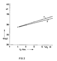
- FIG. 1 shows a device according to the invention and in Fig. 2 calibration curves of the oxygen sensor are shown.
- the device shown in FIG. 1 contains a pacemaker 2 and a control unit 4.
- a counter electrode 6 of the pacemaker is connected to the body 8 of a patient.
- the pacemaker 2 is provided with a stimulation electrode 10 and a ° 2 measuring electrode 12, which are each arranged in the heart muscle tissue 14.
- a first input 16 of the control unit 4 is connected to a reference electrode 18 which is arranged in the vicinity of the stimulus or 02 measuring electrode 10 or 12 in the heart muscle tissue 14.
- a second input 20 of the control unit 4 is connected to the O 2 measuring electrode 12 and a third input 22 of the control unit 4 to the stimulation electrode 10.
- the O 2 measuring electrode 12 is preferably made of smooth glassy carbon and the stimulating electrode 10 is preferably made of activated glassy carbon.
- the lines 24 of the stimulus, O 2 measurement and reference electrodes are in a common elec arranged trodentent, which is shown in the figure by a dashed line 26.
- the control unit 4 contains two electronic switches 28 and 30 and processing electronics 32, which can be a microprocessor, for example.
- the second input 20 and the third input 22 of the control unit 4 are connected to the processing electronics 32 by means of the electronic switches 28 and 30.
- the electronic switches 28 and 30 are controlled by the processing electronics 32 such that both switches are closed at the same time.
- the switches 28 and 30 are connected to the processing electronics by dashed lines (not shown in more detail in FIG. 1).
- the first input 16 of the control unit 4 is connected directly to the processing electronics 32.
- the output 34 of the control unit 4 is connected to the pacemaker 2.
- the stimulation electrode 10 and the 0 2 measurement electrode 12 are loaded in parallel with the cathodic stimulation pulses of the pacemaker 2.
- the switch 28 When the switch 28 is closed, the potential of the O 2 measurement electrode 12 with respect to the reference electrode 18 is measured before the next stimulus imposes the O 2 measurement electrode 12.
- the stimulus impulses are used as trigger impulses.
- the time period in which the potential of the O 2 measuring electrode 12 can be measured is, for example, 0.5 to 1 ms. Within this period the potential is 0 ? -Measuring electrode 12 at least approximately constant.
- the processing electronics 32 assigns an oxygen concentration value to each potential value. Depending on the oxygen concentration values, control impulses reach the pacemaker 2 via the output 34 of the control unit 4. As the oxygen concentration in the blood or tissue increases, the number of beats / minute of the pacemaker 2 decreases.
- the processing electronics assign an oxygen concentration value to each of these potential differences, thus increasing or decreasing the number of beats / minute of the pacemaker 2 to a predetermined value .
- a straight line a with a positive slope represents the potential profile of the 0 2 measuring electrode 12 in an electrolyte, which is loaded with cathodic stimulation pulses of, for example, 5 V and a pulse length of approximately 0.5 ms.
- This electrolyte contains for example 0.9% sodium chloride (NaCl) and for example 0.1% sodium hydrogen carbonate (NaHC0 3 ) and forms the basic electrolyte.
- a straight line b with a positive slope likewise represents the potential profile of the 0 2 measuring electrode 12.
- Lines a and b each start at the same starting point, but their gradients are different.
- Line b for example, has a slope of approximately 50 mV / 20% oxygen.
- the straight line b which does not deviate significantly from the straight line a, shows that this measuring method can be used to measure the oxygen concentration in vivo in blood or tissue over a longer period of time, even in the presence of physiological accompanying substances.
Abstract
Description
- Die Erfindung betrifft eine Vorrichtung zur physiologischen Frequenzsteuerung eines mit einer Reizelektrode versehenen Herzschrittmachers mittels einer Steuereinheit sowie Verfahren zum Betrieb einer derartigen Vorrichtung.
- Die gebräuchlichen Anwendungsformen der Schrittmachertherapie sind die permanente und die temporäre Elektrostimulation des Herzens. Gelegentlich wird in primär nicht eindeutig beurteilbaren Fällen die Kombination beider Verfahren erforderlich sein. Die permanente Elektrostimulation des Herzens wird angewendet bei Auftreten Adams-Stokes'scher Anfälle oder bei totalem AV-Block (AV = Atrioventrikularknoten). In Fällen von bradykarder Herzarrhythmie ist eine temporäre Elektrostimulation des Herzens vorzusehen, damit die körperliche Leistungsfähigkeit der Betroffenen verbessert wird.
- Für die permanente Elektrostimulation des Herzens sind Herzschrittmacher bekannt, die einen festfrequenten Generator enthalten, der konstant beispielsweise 70 Stromstöße/Minute abgibt. Diese Herzschrittmacher sind einfach aufgebaut und wenig störanfällig, haben relativ kleine Abmessungen und erreichen auch bei normalen chemischen Batterien eine hohe Lebensdauer. Derartige Herzschrittmacher können insbesondere bei alten Menschen angewendet werden, denen ein Herzzeitvolumen auf der Basis von 70 Schlägen/Minute das noch zumutbare Ausmaß der körperlichen Belastbarkeit verschafft. Ausserdem wird ein Eigenrhythmus des Herzens des Patienten wenigstens annähernd unterdrückt. Beim Auftreten von spontanen patienteneigenen Aktionen aus einem oder mehreren Automatiezentren führt diese Parasystolie nicht nur zur irregulären Schlagfolge mit gehäuften Vorkommen gestörter Schrittmacherimpulse. Sie kann insbesondere tachykarde Zustände bis hin zum Kammerflimmern auslösen, wenn die künstlichen Stimuli in die vulnerable Phase, d.h. die T-Welle der vorangegangenen Eigenaktion, einfallen.
- Außerdem sind verschiedene Typen sogenannter Bedarfsschrittmacher bekannt. Bei den Demand-Geräten wird der Impuls des Herzschrittmachers über die im Ventrikel liegende Elektrode durch das Potential der R-Zacke der Eigenaktionen solange gehemmt, wie deren Frequenz beispielsweise über 70 Schläge/Minute liegt. Sinkt sie unter diesen Wert ab, so schaltet sich das Gerät automatisch ein und übernimmt die Stimulation. Bei dem "Stand-by-Pacer" wirkt die R-Zacke des Eigenrhythmus über die Elektrode als Triggerimpuls, dem sich das Gerät im Frequenzbereich beispielsweise zwischen 70 und 150 Schläge/Minute mit angepaßter Signalaussetzung unterordnet. Fallen Eigenimpulse aus bzw. sind die R-Zackenabstände niedriger als die gerätespezifische Refraktärzeit, die beispielsweise zwischen 300 und 400 ms beträgt, wird künstlich stimuliert. Überschreiten diese indessen einen oberen vorbestimmten Minutenwert von beispielsweise 150, so halbiert der Herzschrittmacher die Frequenz, d.h. er übernimmt die elektrische Reizung des Herzen mit entsprechend reduzierter Impulsabgabe. Durch diese beiden Typen von Bedarfsschrittmachern wird die Parasystolie vermieden und man erhält ein geordnetes Nebeneinander von Eigenrhythmus und künstlicher Stimulation.
- Ferner ist eine elektrochemische Vorrichtung zur Bestimmung des Sauerstoffgehaltes einer Flüssigkeit bekannt. Die Meßzelle dieser Vorrichtung besteht aus einem röhrenförmigen Körper, in dem eine Kathode und eine Anode in einem Elektrolyt angeordnet sind. Die eine Stirnseite der Meßzelle ist mit einer Membran versehen, die mit einem Dichtring und einer mit einer Öffnung versehenen Kappe befestigt ist. Diese Membran trennt die zu untersuchende Flüssigkeit von der Elektrodenanordnung. Das Meßprinzip besteht in der elektrochemischen Reduktion von Sauerstoff (02), wobei durch die Membran ein Sauerstoffdiffusionsgrenzstrom an der Elektrode bewirkt wird. Dadurch erhält man ein konzentrationsproportionales Meßsignal (US-Patentschrift 2 913 386). Mit einer derart aufgebauten Meßzelle kann man beispielsweise die Sauerstoffkonzentration im Blut bzw. Gewebe aber nur kurzzeitig, beispielsweise für einige Tage, in vivo messen, da die Meßzelle durch sich bildende Bindegewebsschichten umschlossen und das Meßsignal somit verfälscht wird.
- Der Erfindung liegt die Aufgabe zugrunde, einen Herzschrittmacher anzugeben, der eine der Physiologie angepaßte, einfache und wenig störanfällige Arbeitsweise ermöglicht.
- Diese Aufgabe wird erfindungsgemäß gelöst durch eine Vorrichtung mit den Merkmalen des Anspruchs 1.
- Bei einer ersten Ausführungsform der erfindungsgemäßen Vorrichtung wird die 02-MeBelektrode jeweils parallel zur Reizelektrode mit einem Reizimpuls belastet und jeweils vor der nächsten Belastung der 0 2-Meßelektrode (und der Reizelektrode) mit einem weiteren Reizimpuls das Potential der O2-Meßelektrode, bezogen auf eine Bezugselektrode, gemessen. Das gemessene Potential entspricht der Sauerstoffkonzentration des Blutes oder des Herzmuskelgewebes. Eine Verarbeitungselektronik ordnet dabei jedem Potential der 02-MeBelektrode einen Sauerstoffkonzentrationswert zu und regelt in Abhängigkeit von dieser Sauerstoffkonzentration die Frequenz, d.h. die Anzahl der Schläge/Minute des Herzens. Somit erhält man einen Herzschrittmacher mit einem implantierbaren Sauerstoffsensor, der eine der Physiologie angepaßte Arbeitsweise ermöglicht.
- Bei einer zweiten Ausführungsform der erfindungsgemässen Vorrichtung wird die °2-Meßelektrode ebenfalls parallel zur Reizelektrode mit einem Reizimpuls belastet. Hierbei wird jedoch jeweils vor der nächsten Belastung der O2-Meßelektrode mit einem Reizimpuls die Potentialdifferenz zwischen der O2-Meßelektrode und der Reizelektrode gemessen. Die 02-Meßelektrode besteht vorzugsweise aus glattem Glaskohlenstoff und die Reizelektrode vorzugsweise aus aktiviertem Glaskohlenstoff. Eine derartige Reizelektrode hat eine hohe Doppelschichtkapazität, woraus eine geringe Polarisation resultiert. Bei sich schnell ändernden Sauerstoffkonzentrationen im Blut bzw. Gewebe behält die Reizelektrode aus aktiviertem Glaskohlenstoff ihr Potential bei, die 02-Meaelek- trode aus glattem Glaskohlenstoff ändert aber ihr Potential in Abhängigkeit von der Sauerstoffkonzentration. Durch die Differenzbildung der Potentiale werden mögliche - für beide Elektroden wirksam werdende - Einflüsse von körpereigenen Substanzen, deren Konzentrationen sich langsamer ändern als die des Sauerstoffs, eliminiert. Somit kann man sich schnell ändernde Sauerstoffkonzentrationen im Blut bzw. Gewebe messen und dementsprechend die Frequenz des Herzschrittmachers steuern.
- Bei der erfindungsgemäßen Vorrichtung bilden der Herzschrittmacher und die Steuereinheit vorteilhaft eine gemeinsame Baueinheit. Außerdem können die Leitungen der °2-Meßelektrode und der Bezugselektrode gemeinsam mit der Leitung der Reizelektrode in einem Elektrodenkabel angeordnet sein. Auf diese Weise erhält man einen physiologisch gesteuerten Herzschrittmacher, dessen Bauform sich gegenüber bekannten Herzschrittmacherbauformen nicht wesentlich vergrößert hat. Auch der operative Eingriff wird durch diese Bauform nicht komplizierter.
- Zur weiteren Erläuterung wird auf die Zeichnung Bezug genommen, in der ein Ausführungsbeispiel einer Vorrichtung zur physiologischen Frequenzsteuerung eines mit einer Reizelektrode versehenen Herzschrittmachers schematisch veranschaulicht ist. Fig. 1 zeigt eine Vorrichtung gemäß der Erfindung und in Fig. 2 sind Eichkurven des Sauerstoffsensors dargestellt.
- Die in Fig. 1 dargestellte Vorrichtung enthält einen Herzschrittmacher 2 und eine Steuereinheit 4. Eine Gegenelektrode 6 des Herzschrittmachers ist mit dem Körper 8 eines Patienten verbunden. Der Herzschrittmacher 2 ist mit einer Reizelektrode 10 und einer °2-Meßelektrode 12 versehen, die jeweils im Herzmuskelgewebe 14 angeordnet sind. Ein erster Eingang 16 der Steuereinheit 4 ist mit einer Bezugselektrode 18 verbunden, die in der Nähe der Reiz- bzw. 02-Meßelektrode 10 bzw. 12 im Herzmuskelgewebe 14 angeordnet ist. Ein zweiter Eingang 20 der Steuereinheit 4 ist mit der O2-Meßelektrode 12 und ein dritter Eingang 22 der Steuereinheit 4 mit der Reizelektrode 10 verbunden. Die O2-Meßelektrode 12 besteht vorzugsweise aus glattem Glaskohlenstoff und die Reizelektrode 10 vorzugsweise aus aktiviertem Glaskohlenstoff. Die Leitungen 24 der Reiz-, O2-Meß-und Bezugselektrode sind in einem gemeinsamen Elektrodenkabel angeordnet, das in der Figur durch eine gestrichelte Linie 26 dargestellt ist. Die Steuereinheit 4 enthält zwei elektronische Schalter 28 und 30 und eine Verarbeitungselektronik 32, die beispielsweise ein Mikroprozessor sein kann. Der zweite Eingang 20 und der dritte Eingang 22 der Steuereinheit 4 sind mit Hilfe der elektronischen Schalter 28 und 30 mit der Verarbeitungselektronik 32 verbunden. Die elektronischen Schalter 28 und 30 werden von der Verarbeitungselektronik 32 derart gesteuert, daß beide Schalter gleichzeitig geschlossen sind. Die Schalter 28 und 30 sind dazu durch in Fig. 1 nicht näher bezeichnete gestrichelte Linien an die Verarbeitungselektronik angeschlossen. Der erste Eingang 16 der Steuereinheit 4 ist direkt mit der Verarbeitungselektronik 32 verbunden. Der Ausgang 34 der Steuereinheit 4 ist mit dem Herzschrittmacher 2 verbunden.
- Die Reizelektrode 10 und die 02-Meßeiektrode 12 werden parallel mit den kathodischen Reizimpulsen des Herzschrittmachers 2 belastet. Wenn der Schalter 28 geschlossen ist, wird das Potential der O2-Meßelektrode 12 in bezug auf die Bezugselektrode 18 gemessen, bevor der nächste Reizimpuls die O2-Meßelektrode 12 belastet. Man benutzt die Reizimpulse als Triggerimpulse. Die Zeitspanne, in der das Potential der O2-Meßelektrode 12 gemessen werden kann, beträgt beispielsweise 0,5 bis 1 ms. Innerhalb dieser Zeitspanne ist das Potential der 0?-Meßelektrode 12 wenigstens annähernd konstant. Die Verarbeitungselektronik 32 ordnet jedem Potentialwert einen Sauerstoffkonzentrationswert zu. In Abhängigkeit von den Sauerstoffkonzentrationswerten gelangen Steuerimpulse über den Ausgang 34 der Steuereinheit 4 zum Herzschrittmacher 2. Bei ansteigender Sauerstoffkonzentration im Blut bzw. Gewebe sinkt die Anzahl der Schläge/ Minute des Herzschrittmachers 2.
- Wird die Potentialdifferenz zwischen 02-Meßelektrode und Reizelektrode gemessen, d.h. wird ohne zusätzliche Bezugselektrode gearbeitet, so wird auch diesen Potentialdifferenzen von der Verarbeitungselektronik jeweils ein Sauerstoffkonzentrationswert zugeordnet und somit die Anzahl der Schläge/Minute des Herzschrittmachers 2 auf einen vorbestimmten Wert erhöht bzw. erniedrigt.
- In den Eichkurven nach Fig. 2 ist das Potential f/AgCl der 02-Meßelektrode 12 über der Sauerstoffkonzentration aufgetragen. Eine Gerade a mit einer positiven Steigung stellt den Potentialverlauf der 0 2-Meßelektrode 12 in einem Elektrolyten dar, die mit kathodischen Reizimpulsen von beispielsweise 5 V und einer Impulslänge von etwa 0,5 ms belastet ist. Dieser Elektrolyt enthält beispielsweise 0,9 % Natriumchlorid (NaCl) und beispielsweise 0,1 % Natriumhydrogencarbonat (NaHC03) und bildet den Grundelektrolyt. Eine Gerade b mit positiver Steigung stellt ebenfalls den Potentialverlauf der 02-Meßelektrode 12 dar. Jedoch wurden hierbei dem Grundelektrolyt physiologische Substanzen, wie beispielsweise Glucose, Harnstoff und Aminosäuremischungen in ihrer physiologisch maximalen Konzentration, zugesetzt. Die Geraden a und b beginnen jeweils im selben Ausgangspunkt, jedoch sind ihre Steigungen unterschiedlich. Die Gerade b hat beispielsweise eine Steigung von etwa 50 mV/20% Sauerstoff. Durch die Gerade b, die nicht wesentlich von der Geraden a abweicht, wird gezeigt, daß man mit dieser Meßmethode die Sauerstoffkonzentration in vivo über einen längeren Zeitraum in Blut bzw. Gewebe auch in Anwesenheit von physiologischen Begleitsubstanzen messen kann.
Claims (10)
Priority Applications (1)
| Application Number | Priority Date | Filing Date | Title |
|---|---|---|---|
| AT85109393T ATE40525T1 (de) | 1984-08-10 | 1985-07-26 | Vorrichtung zur physiologischen frequenzsteuerung eines mit einer reizelektrode versehenen herzschrittmachers. |
Applications Claiming Priority (2)
| Application Number | Priority Date | Filing Date | Title |
|---|---|---|---|
| DE19843429596 DE3429596A1 (de) | 1984-08-10 | 1984-08-10 | Vorrichtung zur physiologischen frequenzsteuerung eines mit einer reizelektrode versehenen herzschrittmachers |
| DE3429596 | 1984-08-10 |
Publications (2)
| Publication Number | Publication Date |
|---|---|
| EP0170997A1 true EP0170997A1 (de) | 1986-02-12 |
| EP0170997B1 EP0170997B1 (de) | 1989-02-01 |
Family
ID=6242848
Family Applications (1)
| Application Number | Title | Priority Date | Filing Date |
|---|---|---|---|
| EP85109393A Expired EP0170997B1 (de) | 1984-08-10 | 1985-07-26 | Vorrichtung zur physiologischen Frequenzsteuerung eines mit einer Reizelektrode versehenen Herzschrittmachers |
Country Status (5)
| Country | Link |
|---|---|
| US (1) | US4779618A (de) |
| EP (1) | EP0170997B1 (de) |
| JP (1) | JPH066174B2 (de) |
| AT (1) | ATE40525T1 (de) |
| DE (2) | DE3429596A1 (de) |
Cited By (1)
| Publication number | Priority date | Publication date | Assignee | Title |
|---|---|---|---|---|
| EP0593990A1 (de) * | 1992-10-19 | 1994-04-27 | Pacesetter AB | Implantierbarer Sauerstoffsensor für einen Herzschrittmacher |
Families Citing this family (170)
| Publication number | Priority date | Publication date | Assignee | Title |
|---|---|---|---|---|
| DE58907652D1 (de) * | 1988-02-05 | 1994-06-16 | Siemens Ag | Verfahren zur anpassung der stimulationsfrequenz eines herzschrittmachers an die belastung eines patienten. |
| US4964406A (en) * | 1989-05-19 | 1990-10-23 | Ventritex, Inc. | Implantable cardiac defibrillator employing a switched capacitor stage having a non-50/50 duty cycle |
| US5593852A (en) | 1993-12-02 | 1997-01-14 | Heller; Adam | Subcutaneous glucose electrode |
| JPH04278450A (ja) | 1991-03-04 | 1992-10-05 | Adam Heller | バイオセンサー及び分析物を分析する方法 |
| SE9600511D0 (sv) * | 1996-02-12 | 1996-02-12 | Pacesetter Ab | Bipolar sensor electrode |
| SE9603569D0 (sv) * | 1996-09-30 | 1996-09-30 | Pacesetter Ab | Electrochemical sensor |
| US5910112A (en) * | 1996-11-08 | 1999-06-08 | Northwestern University | 23 NA and 39 K imaging of the heart |
| SE9703957D0 (sv) | 1997-10-29 | 1997-10-29 | Pacesetter Ab | Method and device for sensing |
| SE9703958D0 (sv) | 1997-10-29 | 1997-10-29 | Pacesetter Ab | Method and device for determination of concentration |
| US5978710A (en) * | 1998-01-23 | 1999-11-02 | Sulzer Intermedics Inc. | Implantable cardiac stimulator with safe noise mode |
| US6134461A (en) | 1998-03-04 | 2000-10-17 | E. Heller & Company | Electrochemical analyte |
| US8480580B2 (en) | 1998-04-30 | 2013-07-09 | Abbott Diabetes Care Inc. | Analyte monitoring device and methods of use |
| US6949816B2 (en) | 2003-04-21 | 2005-09-27 | Motorola, Inc. | Semiconductor component having first surface area for electrically coupling to a semiconductor chip and second surface area for electrically coupling to a substrate, and method of manufacturing same |
| US6175752B1 (en) | 1998-04-30 | 2001-01-16 | Therasense, Inc. | Analyte monitoring device and methods of use |
| US8465425B2 (en) | 1998-04-30 | 2013-06-18 | Abbott Diabetes Care Inc. | Analyte monitoring device and methods of use |
| US9066695B2 (en) | 1998-04-30 | 2015-06-30 | Abbott Diabetes Care Inc. | Analyte monitoring device and methods of use |
| US8346337B2 (en) | 1998-04-30 | 2013-01-01 | Abbott Diabetes Care Inc. | Analyte monitoring device and methods of use |
| US8688188B2 (en) | 1998-04-30 | 2014-04-01 | Abbott Diabetes Care Inc. | Analyte monitoring device and methods of use |
| US8974386B2 (en) | 1998-04-30 | 2015-03-10 | Abbott Diabetes Care Inc. | Analyte monitoring device and methods of use |
| US6560471B1 (en) | 2001-01-02 | 2003-05-06 | Therasense, Inc. | Analyte monitoring device and methods of use |
| AU2002309528A1 (en) | 2001-04-02 | 2002-10-15 | Therasense, Inc. | Blood glucose tracking apparatus and methods |
| US7381184B2 (en) | 2002-11-05 | 2008-06-03 | Abbott Diabetes Care Inc. | Sensor inserter assembly |
| AU2003303597A1 (en) | 2002-12-31 | 2004-07-29 | Therasense, Inc. | Continuous glucose monitoring system and methods of use |
| US8066639B2 (en) | 2003-06-10 | 2011-11-29 | Abbott Diabetes Care Inc. | Glucose measuring device for use in personal area network |
| US20190357827A1 (en) | 2003-08-01 | 2019-11-28 | Dexcom, Inc. | Analyte sensor |
| US7920906B2 (en) | 2005-03-10 | 2011-04-05 | Dexcom, Inc. | System and methods for processing analyte sensor data for sensor calibration |
| US7299082B2 (en) | 2003-10-31 | 2007-11-20 | Abbott Diabetes Care, Inc. | Method of calibrating an analyte-measurement device, and associated methods, devices and systems |
| USD902408S1 (en) | 2003-11-05 | 2020-11-17 | Abbott Diabetes Care Inc. | Analyte sensor control unit |
| WO2005089103A2 (en) | 2004-02-17 | 2005-09-29 | Therasense, Inc. | Method and system for providing data communication in continuous glucose monitoring and management system |
| CA2572455C (en) | 2004-06-04 | 2014-10-28 | Therasense, Inc. | Diabetes care host-client architecture and data management system |
| US7713574B2 (en) | 2004-07-13 | 2010-05-11 | Dexcom, Inc. | Transcutaneous analyte sensor |
| US7493174B2 (en) * | 2004-09-23 | 2009-02-17 | Medtronic, Inc. | Implantable medical lead |
| US7731657B2 (en) | 2005-08-30 | 2010-06-08 | Abbott Diabetes Care Inc. | Analyte sensor introducer and methods of use |
| US20090105569A1 (en) | 2006-04-28 | 2009-04-23 | Abbott Diabetes Care, Inc. | Introducer Assembly and Methods of Use |
| US8571624B2 (en) | 2004-12-29 | 2013-10-29 | Abbott Diabetes Care Inc. | Method and apparatus for mounting a data transmission device in a communication system |
| US9636450B2 (en) | 2007-02-19 | 2017-05-02 | Udo Hoss | Pump system modular components for delivering medication and analyte sensing at seperate insertion sites |
| US8029441B2 (en) | 2006-02-28 | 2011-10-04 | Abbott Diabetes Care Inc. | Analyte sensor transmitter unit configuration for a data monitoring and management system |
| US8545403B2 (en) | 2005-12-28 | 2013-10-01 | Abbott Diabetes Care Inc. | Medical device insertion |
| US9259175B2 (en) | 2006-10-23 | 2016-02-16 | Abbott Diabetes Care, Inc. | Flexible patch for fluid delivery and monitoring body analytes |
| US9398882B2 (en) | 2005-09-30 | 2016-07-26 | Abbott Diabetes Care Inc. | Method and apparatus for providing analyte sensor and data processing device |
| US7697967B2 (en) | 2005-12-28 | 2010-04-13 | Abbott Diabetes Care Inc. | Method and apparatus for providing analyte sensor insertion |
| US9572534B2 (en) | 2010-06-29 | 2017-02-21 | Abbott Diabetes Care Inc. | Devices, systems and methods for on-skin or on-body mounting of medical devices |
| US9743862B2 (en) | 2011-03-31 | 2017-08-29 | Abbott Diabetes Care Inc. | Systems and methods for transcutaneously implanting medical devices |
| US10226207B2 (en) | 2004-12-29 | 2019-03-12 | Abbott Diabetes Care Inc. | Sensor inserter having introducer |
| US9788771B2 (en) | 2006-10-23 | 2017-10-17 | Abbott Diabetes Care Inc. | Variable speed sensor insertion devices and methods of use |
| US8512243B2 (en) | 2005-09-30 | 2013-08-20 | Abbott Diabetes Care Inc. | Integrated introducer and transmitter assembly and methods of use |
| US9351669B2 (en) | 2009-09-30 | 2016-05-31 | Abbott Diabetes Care Inc. | Interconnect for on-body analyte monitoring device |
| US7883464B2 (en) | 2005-09-30 | 2011-02-08 | Abbott Diabetes Care Inc. | Integrated transmitter unit and sensor introducer mechanism and methods of use |
| US8333714B2 (en) | 2006-09-10 | 2012-12-18 | Abbott Diabetes Care Inc. | Method and system for providing an integrated analyte sensor insertion device and data processing unit |
| US8112240B2 (en) | 2005-04-29 | 2012-02-07 | Abbott Diabetes Care Inc. | Method and apparatus for providing leak detection in data monitoring and management systems |
| EP1921980A4 (de) | 2005-08-31 | 2010-03-10 | Univ Virginia | Verbesserung der genauigkeit von kontinuierlichen glucosesensoren |
| US8880138B2 (en) | 2005-09-30 | 2014-11-04 | Abbott Diabetes Care Inc. | Device for channeling fluid and methods of use |
| US9521968B2 (en) | 2005-09-30 | 2016-12-20 | Abbott Diabetes Care Inc. | Analyte sensor retention mechanism and methods of use |
| US7766829B2 (en) | 2005-11-04 | 2010-08-03 | Abbott Diabetes Care Inc. | Method and system for providing basal profile modification in analyte monitoring and management systems |
| US11298058B2 (en) | 2005-12-28 | 2022-04-12 | Abbott Diabetes Care Inc. | Method and apparatus for providing analyte sensor insertion |
| US20070169533A1 (en) * | 2005-12-30 | 2007-07-26 | Medtronic Minimed, Inc. | Methods and systems for detecting the hydration of sensors |
| US20070173712A1 (en) | 2005-12-30 | 2007-07-26 | Medtronic Minimed, Inc. | Method of and system for stabilization of sensors |
| US7736310B2 (en) | 2006-01-30 | 2010-06-15 | Abbott Diabetes Care Inc. | On-body medical device securement |
| US7826879B2 (en) | 2006-02-28 | 2010-11-02 | Abbott Diabetes Care Inc. | Analyte sensors and methods of use |
| US7885698B2 (en) | 2006-02-28 | 2011-02-08 | Abbott Diabetes Care Inc. | Method and system for providing continuous calibration of implantable analyte sensors |
| US8224415B2 (en) | 2009-01-29 | 2012-07-17 | Abbott Diabetes Care Inc. | Method and device for providing offset model based calibration for analyte sensor |
| US7620438B2 (en) | 2006-03-31 | 2009-11-17 | Abbott Diabetes Care Inc. | Method and system for powering an electronic device |
| US9675290B2 (en) | 2012-10-30 | 2017-06-13 | Abbott Diabetes Care Inc. | Sensitivity calibration of in vivo sensors used to measure analyte concentration |
| US7653425B2 (en) | 2006-08-09 | 2010-01-26 | Abbott Diabetes Care Inc. | Method and system for providing calibration of an analyte sensor in an analyte monitoring system |
| US8140312B2 (en) | 2007-05-14 | 2012-03-20 | Abbott Diabetes Care Inc. | Method and system for determining analyte levels |
| US8473022B2 (en) | 2008-01-31 | 2013-06-25 | Abbott Diabetes Care Inc. | Analyte sensor with time lag compensation |
| US8226891B2 (en) | 2006-03-31 | 2012-07-24 | Abbott Diabetes Care Inc. | Analyte monitoring devices and methods therefor |
| US9392969B2 (en) | 2008-08-31 | 2016-07-19 | Abbott Diabetes Care Inc. | Closed loop control and signal attenuation detection |
| US8346335B2 (en) | 2008-03-28 | 2013-01-01 | Abbott Diabetes Care Inc. | Analyte sensor calibration management |
| US7618369B2 (en) | 2006-10-02 | 2009-11-17 | Abbott Diabetes Care Inc. | Method and system for dynamically updating calibration parameters for an analyte sensor |
| US7801582B2 (en) | 2006-03-31 | 2010-09-21 | Abbott Diabetes Care Inc. | Analyte monitoring and management system and methods therefor |
| US8478557B2 (en) | 2009-07-31 | 2013-07-02 | Abbott Diabetes Care Inc. | Method and apparatus for providing analyte monitoring system calibration accuracy |
| US8374668B1 (en) | 2007-10-23 | 2013-02-12 | Abbott Diabetes Care Inc. | Analyte sensor with lag compensation |
| US7630748B2 (en) | 2006-10-25 | 2009-12-08 | Abbott Diabetes Care Inc. | Method and system for providing analyte monitoring |
| US8219173B2 (en) | 2008-09-30 | 2012-07-10 | Abbott Diabetes Care Inc. | Optimizing analyte sensor calibration |
| US20080071157A1 (en) | 2006-06-07 | 2008-03-20 | Abbott Diabetes Care, Inc. | Analyte monitoring system and method |
| MX2009004530A (es) | 2006-10-26 | 2009-08-13 | Abbott Diabetes Care Inc | Método, sistema y producto de programa de computacion para la deteccion en tiempo real de la disminucion de sensibilidad en los sensores analitos. |
| US8121857B2 (en) | 2007-02-15 | 2012-02-21 | Abbott Diabetes Care Inc. | Device and method for automatic data acquisition and/or detection |
| US20080199894A1 (en) | 2007-02-15 | 2008-08-21 | Abbott Diabetes Care, Inc. | Device and method for automatic data acquisition and/or detection |
| US8930203B2 (en) | 2007-02-18 | 2015-01-06 | Abbott Diabetes Care Inc. | Multi-function analyte test device and methods therefor |
| US8732188B2 (en) | 2007-02-18 | 2014-05-20 | Abbott Diabetes Care Inc. | Method and system for providing contextual based medication dosage determination |
| US8123686B2 (en) | 2007-03-01 | 2012-02-28 | Abbott Diabetes Care Inc. | Method and apparatus for providing rolling data in communication systems |
| EP2137637A4 (de) | 2007-04-14 | 2012-06-20 | Abbott Diabetes Care Inc | Verfahren und vorrichtung zur datenverarbeitung und steuerung in einem medizinischen kommunikationssystem |
| ES2784736T3 (es) | 2007-04-14 | 2020-09-30 | Abbott Diabetes Care Inc | Procedimiento y aparato para proporcionar el procesamiento y control de datos en un sistema de comunicación médica |
| US10111608B2 (en) | 2007-04-14 | 2018-10-30 | Abbott Diabetes Care Inc. | Method and apparatus for providing data processing and control in medical communication system |
| ES2461090T3 (es) | 2007-04-14 | 2014-05-16 | Abbott Diabetes Care Inc. | Procedimiento y aparato para proporcionar tratamiento y control de datos en un sistema de comunicación médica |
| CA2683962C (en) | 2007-04-14 | 2017-06-06 | Abbott Diabetes Care Inc. | Method and apparatus for providing data processing and control in medical communication system |
| EP2146622B1 (de) | 2007-04-14 | 2016-05-11 | Abbott Diabetes Care Inc. | Verfahren und vorrichtung für dynamische mehrstufige signalverstärkung bei einer medizinischen vorrichtung |
| US7928850B2 (en) | 2007-05-08 | 2011-04-19 | Abbott Diabetes Care Inc. | Analyte monitoring system and methods |
| US8461985B2 (en) | 2007-05-08 | 2013-06-11 | Abbott Diabetes Care Inc. | Analyte monitoring system and methods |
| US8665091B2 (en) | 2007-05-08 | 2014-03-04 | Abbott Diabetes Care Inc. | Method and device for determining elapsed sensor life |
| US8456301B2 (en) | 2007-05-08 | 2013-06-04 | Abbott Diabetes Care Inc. | Analyte monitoring system and methods |
| US8260558B2 (en) | 2007-05-14 | 2012-09-04 | Abbott Diabetes Care Inc. | Method and apparatus for providing data processing and control in a medical communication system |
| US10002233B2 (en) | 2007-05-14 | 2018-06-19 | Abbott Diabetes Care Inc. | Method and apparatus for providing data processing and control in a medical communication system |
| US8103471B2 (en) | 2007-05-14 | 2012-01-24 | Abbott Diabetes Care Inc. | Method and apparatus for providing data processing and control in a medical communication system |
| US9125548B2 (en) | 2007-05-14 | 2015-09-08 | Abbott Diabetes Care Inc. | Method and apparatus for providing data processing and control in a medical communication system |
| US7996158B2 (en) | 2007-05-14 | 2011-08-09 | Abbott Diabetes Care Inc. | Method and apparatus for providing data processing and control in a medical communication system |
| US8560038B2 (en) | 2007-05-14 | 2013-10-15 | Abbott Diabetes Care Inc. | Method and apparatus for providing data processing and control in a medical communication system |
| US8600681B2 (en) | 2007-05-14 | 2013-12-03 | Abbott Diabetes Care Inc. | Method and apparatus for providing data processing and control in a medical communication system |
| US8444560B2 (en) | 2007-05-14 | 2013-05-21 | Abbott Diabetes Care Inc. | Method and apparatus for providing data processing and control in a medical communication system |
| US8239166B2 (en) | 2007-05-14 | 2012-08-07 | Abbott Diabetes Care Inc. | Method and apparatus for providing data processing and control in a medical communication system |
| WO2008150917A1 (en) | 2007-05-31 | 2008-12-11 | Abbott Diabetes Care, Inc. | Insertion devices and methods |
| AU2008265542B2 (en) | 2007-06-21 | 2014-07-24 | Abbott Diabetes Care Inc. | Health monitor |
| WO2008157820A1 (en) | 2007-06-21 | 2008-12-24 | Abbott Diabetes Care, Inc. | Health management devices and methods |
| US8160900B2 (en) | 2007-06-29 | 2012-04-17 | Abbott Diabetes Care Inc. | Analyte monitoring and management device and method to analyze the frequency of user interaction with the device |
| US8834366B2 (en) | 2007-07-31 | 2014-09-16 | Abbott Diabetes Care Inc. | Method and apparatus for providing analyte sensor calibration |
| US7768386B2 (en) | 2007-07-31 | 2010-08-03 | Abbott Diabetes Care Inc. | Method and apparatus for providing data processing and control in a medical communication system |
| US8377031B2 (en) | 2007-10-23 | 2013-02-19 | Abbott Diabetes Care Inc. | Closed loop control system with safety parameters and methods |
| US8409093B2 (en) | 2007-10-23 | 2013-04-02 | Abbott Diabetes Care Inc. | Assessing measures of glycemic variability |
| US8216138B1 (en) | 2007-10-23 | 2012-07-10 | Abbott Diabetes Care Inc. | Correlation of alternative site blood and interstitial fluid glucose concentrations to venous glucose concentration |
| US20090164239A1 (en) | 2007-12-19 | 2009-06-25 | Abbott Diabetes Care, Inc. | Dynamic Display Of Glucose Information |
| EP2262543B1 (de) | 2008-04-10 | 2015-07-08 | Abbott Diabetes Care Inc. | Verfahren und system zur sterilisierung eines analytsensors |
| US7826382B2 (en) | 2008-05-30 | 2010-11-02 | Abbott Diabetes Care Inc. | Close proximity communication device and methods |
| US8591410B2 (en) | 2008-05-30 | 2013-11-26 | Abbott Diabetes Care Inc. | Method and apparatus for providing glycemic control |
| US8924159B2 (en) | 2008-05-30 | 2014-12-30 | Abbott Diabetes Care Inc. | Method and apparatus for providing glycemic control |
| WO2010009172A1 (en) | 2008-07-14 | 2010-01-21 | Abbott Diabetes Care Inc. | Closed loop control system interface and methods |
| US9943644B2 (en) | 2008-08-31 | 2018-04-17 | Abbott Diabetes Care Inc. | Closed loop control with reference measurement and methods thereof |
| US8622988B2 (en) | 2008-08-31 | 2014-01-07 | Abbott Diabetes Care Inc. | Variable rate closed loop control and methods |
| US20100057040A1 (en) | 2008-08-31 | 2010-03-04 | Abbott Diabetes Care, Inc. | Robust Closed Loop Control And Methods |
| US8734422B2 (en) | 2008-08-31 | 2014-05-27 | Abbott Diabetes Care Inc. | Closed loop control with improved alarm functions |
| US8986208B2 (en) | 2008-09-30 | 2015-03-24 | Abbott Diabetes Care Inc. | Analyte sensor sensitivity attenuation mitigation |
| US9149220B2 (en) | 2011-04-15 | 2015-10-06 | Dexcom, Inc. | Advanced analyte sensor calibration and error detection |
| US9326707B2 (en) | 2008-11-10 | 2016-05-03 | Abbott Diabetes Care Inc. | Alarm characterization for analyte monitoring devices and systems |
| US8103456B2 (en) | 2009-01-29 | 2012-01-24 | Abbott Diabetes Care Inc. | Method and device for early signal attenuation detection using blood glucose measurements |
| US9402544B2 (en) | 2009-02-03 | 2016-08-02 | Abbott Diabetes Care Inc. | Analyte sensor and apparatus for insertion of the sensor |
| WO2010121084A1 (en) | 2009-04-15 | 2010-10-21 | Abbott Diabetes Care Inc. | Analyte monitoring system having an alert |
| EP2419015A4 (de) | 2009-04-16 | 2014-08-20 | Abbott Diabetes Care Inc | Kalibrierung eines analytsensors |
| WO2010127050A1 (en) | 2009-04-28 | 2010-11-04 | Abbott Diabetes Care Inc. | Error detection in critical repeating data in a wireless sensor system |
| EP2425209A4 (de) | 2009-04-29 | 2013-01-09 | Abbott Diabetes Care Inc | Verfahren und system für die echtzeit-kalibrierung eines analytsensors mit rückwirkender füllung |
| US8368556B2 (en) | 2009-04-29 | 2013-02-05 | Abbott Diabetes Care Inc. | Method and system for providing data communication in continuous glucose monitoring and management system |
| US9184490B2 (en) | 2009-05-29 | 2015-11-10 | Abbott Diabetes Care Inc. | Medical device antenna systems having external antenna configurations |
| US8613892B2 (en) | 2009-06-30 | 2013-12-24 | Abbott Diabetes Care Inc. | Analyte meter with a moveable head and methods of using the same |
| CN104799866A (zh) | 2009-07-23 | 2015-07-29 | 雅培糖尿病护理公司 | 分析物监测装置 |
| LT3718922T (lt) | 2009-08-31 | 2022-04-25 | Abbott Diabetes Care, Inc. | Gliukozės stebėsenos sistema ir būdas |
| AU2010286917B2 (en) | 2009-08-31 | 2016-03-10 | Abbott Diabetes Care Inc. | Medical devices and methods |
| US9314195B2 (en) | 2009-08-31 | 2016-04-19 | Abbott Diabetes Care Inc. | Analyte signal processing device and methods |
| US8993331B2 (en) | 2009-08-31 | 2015-03-31 | Abbott Diabetes Care Inc. | Analyte monitoring system and methods for managing power and noise |
| EP2482720A4 (de) | 2009-09-29 | 2014-04-23 | Abbott Diabetes Care Inc | Verfahren und vorrichtung zur bereitstellung einer benachrichtigungsfunktion in analytüberwachungssystemen |
| US8185181B2 (en) | 2009-10-30 | 2012-05-22 | Abbott Diabetes Care Inc. | Method and apparatus for detecting false hypoglycemic conditions |
| USD924406S1 (en) | 2010-02-01 | 2021-07-06 | Abbott Diabetes Care Inc. | Analyte sensor inserter |
| WO2011112753A1 (en) | 2010-03-10 | 2011-09-15 | Abbott Diabetes Care Inc. | Systems, devices and methods for managing glucose levels |
| DK3622883T3 (da) | 2010-03-24 | 2021-07-19 | Abbott Diabetes Care Inc | Indførerer til medicinsk indretning og fremgangsmåder til at indføre og anvende medicinske indretninger |
| US8635046B2 (en) | 2010-06-23 | 2014-01-21 | Abbott Diabetes Care Inc. | Method and system for evaluating analyte sensor response characteristics |
| US10092229B2 (en) | 2010-06-29 | 2018-10-09 | Abbott Diabetes Care Inc. | Calibration of analyte measurement system |
| US11064921B2 (en) | 2010-06-29 | 2021-07-20 | Abbott Diabetes Care Inc. | Devices, systems and methods for on-skin or on-body mounting of medical devices |
| EP2624745A4 (de) | 2010-10-07 | 2018-05-23 | Abbott Diabetes Care, Inc. | Analytüberwachungsvorrichtungen und -verfahren |
| EP3583901A3 (de) | 2011-02-28 | 2020-01-15 | Abbott Diabetes Care, Inc. | Vorrichtungen, systeme und verfahren im zusammenhang mit analytüberwachungsvorrichtungen und vorrichtungen damit |
| US10136845B2 (en) | 2011-02-28 | 2018-11-27 | Abbott Diabetes Care Inc. | Devices, systems, and methods associated with analyte monitoring devices and devices incorporating the same |
| WO2013066849A1 (en) | 2011-10-31 | 2013-05-10 | Abbott Diabetes Care Inc. | Model based variable risk false glucose threshold alarm prevention mechanism |
| US9069536B2 (en) | 2011-10-31 | 2015-06-30 | Abbott Diabetes Care Inc. | Electronic devices having integrated reset systems and methods thereof |
| AU2012335830B2 (en) | 2011-11-07 | 2017-05-04 | Abbott Diabetes Care Inc. | Analyte monitoring device and methods |
| US8710993B2 (en) | 2011-11-23 | 2014-04-29 | Abbott Diabetes Care Inc. | Mitigating single point failure of devices in an analyte monitoring system and methods thereof |
| US9317656B2 (en) | 2011-11-23 | 2016-04-19 | Abbott Diabetes Care Inc. | Compatibility mechanisms for devices in a continuous analyte monitoring system and methods thereof |
| WO2013078426A2 (en) | 2011-11-25 | 2013-05-30 | Abbott Diabetes Care Inc. | Analyte monitoring system and methods of use |
| CA3118828C (en) | 2011-12-11 | 2022-11-29 | Abbott Diabetes Care Inc. | Analyte sensor devices, connections, and methods |
| EP2890297B1 (de) | 2012-08-30 | 2018-04-11 | Abbott Diabetes Care, Inc. | Ausfallerkennung bei kontinuierlichen analytüberwachungsdaten bei datenabweichungen |
| US9968306B2 (en) | 2012-09-17 | 2018-05-15 | Abbott Diabetes Care Inc. | Methods and apparatuses for providing adverse condition notification with enhanced wireless communication range in analyte monitoring systems |
| US9907492B2 (en) | 2012-09-26 | 2018-03-06 | Abbott Diabetes Care Inc. | Method and apparatus for improving lag correction during in vivo measurement of analyte concentration with analyte concentration variability and range data |
| US10433773B1 (en) | 2013-03-15 | 2019-10-08 | Abbott Diabetes Care Inc. | Noise rejection methods and apparatus for sparsely sampled analyte sensor data |
| US9474475B1 (en) | 2013-03-15 | 2016-10-25 | Abbott Diabetes Care Inc. | Multi-rate analyte sensor data collection with sample rate configurable signal processing |
| US10076285B2 (en) | 2013-03-15 | 2018-09-18 | Abbott Diabetes Care Inc. | Sensor fault detection using analyte sensor data pattern comparison |
| RU2683203C2 (ru) | 2013-12-31 | 2019-03-26 | Эбботт Дайабитиз Кэр Инк. | Снабженный автономным питанием датчик аналита и использующие его устройства |
| EP4151150A1 (de) | 2014-03-30 | 2023-03-22 | Abbott Diabetes Care, Inc. | Verfahren und gerät zum bestimmen von mahlzeitenbeginn und peak-ereignissen in analytischen überwachungssystemen |
| US10213139B2 (en) | 2015-05-14 | 2019-02-26 | Abbott Diabetes Care Inc. | Systems, devices, and methods for assembling an applicator and sensor control device |
| US10674944B2 (en) | 2015-05-14 | 2020-06-09 | Abbott Diabetes Care Inc. | Compact medical device inserters and related systems and methods |
| EP3319518A4 (de) | 2015-07-10 | 2019-03-13 | Abbott Diabetes Care Inc. | System, vorrichtung und verfahren zur dynamischen glukoseprofilreaktion auf physiologische parameter |
| CN110461217B (zh) | 2017-01-23 | 2022-09-16 | 雅培糖尿病护理公司 | 用于分析物传感器插入的系统、装置和方法 |
| EP3600014A4 (de) | 2017-03-21 | 2020-10-21 | Abbott Diabetes Care Inc. | Verfahren, vorrichtungen und system zur bereitstellung der diagnose und therapie von diabetischen zuständen |
| AU2018354120A1 (en) | 2017-10-24 | 2020-04-23 | Dexcom, Inc. | Pre-connected analyte sensors |
| US11331022B2 (en) | 2017-10-24 | 2022-05-17 | Dexcom, Inc. | Pre-connected analyte sensors |
Citations (2)
| Publication number | Priority date | Publication date | Assignee | Title |
|---|---|---|---|---|
| US4202339A (en) * | 1977-04-21 | 1980-05-13 | Alexander Wirtzfeld | Cardiac pacemaker |
| FR2516797A1 (fr) * | 1981-11-23 | 1983-05-27 | Medtronic Inc | Stimulateur cardiaque avec commande physiologique de la cadence de stimulation |
Family Cites Families (6)
| Publication number | Priority date | Publication date | Assignee | Title |
|---|---|---|---|---|
| US2913386A (en) * | 1956-03-21 | 1959-11-17 | Jr Leland C Clark | Electrochemical device for chemical analysis |
| US3614954A (en) * | 1970-02-09 | 1971-10-26 | Medtronic Inc | Electronic standby defibrillator |
| DE3300694A1 (de) * | 1983-01-11 | 1984-08-09 | Siemens AG, 1000 Berlin und 8000 München | Bipolare elektrode fuer medizinische anwendungen |
| US4467896A (en) * | 1983-06-17 | 1984-08-28 | Black & Decker Inc. | Locking mechanism for a rotary power machine |
| US4499901A (en) * | 1983-06-30 | 1985-02-19 | Critikon, Inc. | Retreated sensing electrode |
| US4549548A (en) * | 1983-09-14 | 1985-10-29 | Vitafin N.V. | Pacemaker system with automatic event-programmed switching between unipolar and bipolar operation |
-
1984
- 1984-08-10 DE DE19843429596 patent/DE3429596A1/de not_active Withdrawn
-
1985
- 1985-07-26 EP EP85109393A patent/EP0170997B1/de not_active Expired
- 1985-07-26 DE DE8585109393T patent/DE3568008D1/de not_active Expired
- 1985-07-26 AT AT85109393T patent/ATE40525T1/de not_active IP Right Cessation
- 1985-08-06 JP JP60173076A patent/JPH066174B2/ja not_active Expired - Lifetime
- 1985-08-12 US US06/764,850 patent/US4779618A/en not_active Expired - Lifetime
Patent Citations (2)
| Publication number | Priority date | Publication date | Assignee | Title |
|---|---|---|---|---|
| US4202339A (en) * | 1977-04-21 | 1980-05-13 | Alexander Wirtzfeld | Cardiac pacemaker |
| FR2516797A1 (fr) * | 1981-11-23 | 1983-05-27 | Medtronic Inc | Stimulateur cardiaque avec commande physiologique de la cadence de stimulation |
Non-Patent Citations (1)
| Title |
|---|
| MEDICAL AND BIOLOGICAL ENGINEERING AND COMPUTING, Band 17, Nr. 7, Juli 1979, Seiten 465-470, IFMBE, Stevenage, Herts, GB; T. SHIGEMITSU et al.: "Electrical properties of glassy-carbon electrodes" * |
Cited By (1)
| Publication number | Priority date | Publication date | Assignee | Title |
|---|---|---|---|---|
| EP0593990A1 (de) * | 1992-10-19 | 1994-04-27 | Pacesetter AB | Implantierbarer Sauerstoffsensor für einen Herzschrittmacher |
Also Published As
| Publication number | Publication date |
|---|---|
| EP0170997B1 (de) | 1989-02-01 |
| US4779618A (en) | 1988-10-25 |
| JPS6148380A (ja) | 1986-03-10 |
| DE3568008D1 (en) | 1989-03-09 |
| JPH066174B2 (ja) | 1994-01-26 |
| DE3429596A1 (de) | 1986-02-20 |
| ATE40525T1 (de) | 1989-02-15 |
Similar Documents
| Publication | Publication Date | Title |
|---|---|---|
| EP0170997B1 (de) | Vorrichtung zur physiologischen Frequenzsteuerung eines mit einer Reizelektrode versehenen Herzschrittmachers | |
| DE60122820T2 (de) | Vorrichtung zur Verringerung der Effekte von evozierten Potentialen bei Polarisationsmessungen in einem Herzschrittmachersystem mit automatischer Erfassung des Einfanges | |
| DE69807986T3 (de) | Herzschrittmacher | |
| DE69629968T2 (de) | Vorrichtung zur Stimulation der Herzfunktion | |
| DE69827420T2 (de) | Herzschrittmacher mit variabler Stimulationsenergie | |
| DE69919983T2 (de) | System zum einleiten von herzkammerflimmern unter verwendung von nahfeldwellenabtastung | |
| DE69917758T2 (de) | Vorrichtung zur behandlung von vorhofsarrythmien | |
| EP2060299B1 (de) | Biventrikulärer Herzstimulator | |
| DE60222071T2 (de) | Implantierbares Herzschrittmachersystem mit Kalibrierung für automatische Erregungsbestätigung | |
| DE60012884T2 (de) | Antitachykardiales schrittmachen | |
| DE3243094A1 (de) | Implantierbares reizstromgeraet | |
| DE3117075C2 (de) | Vorhofsynchroner Herzschrittmacher | |
| DE2727141A1 (de) | Antiarrhythmie-bedarfsschrittmacher | |
| DE2212592A1 (de) | Vorrichtung zum ermitteln von muskelkontraktionen | |
| DE69917629T2 (de) | Vorrichtung zum speichern von physiologischen signalen | |
| EP1062974B1 (de) | Verfahren zur Bestimmung eines variablen Steuer-Parameters eines medizinischen Geräteimplantates | |
| DE2358883A1 (de) | Einadrige kathetervorrichtung und schrittmachverfahren | |
| DE60105989T2 (de) | Implantierbarer herzstimulator | |
| EP0830876B1 (de) | Implantierbare Vorrichtung zur Tachykardie-Früherkennung und -Unterdrückung beim Herzen | |
| EP0586739B1 (de) | Vorrichtung zum Behandeln von Tachyarrhythmien | |
| EP0757574B1 (de) | Stimulationssystem | |
| EP0583499B1 (de) | Verfahren zum Detektieren von Herzkammerflimmern und Vorrichtung zum Detektieren und Behandeln von Herzkammerflimmern | |
| EP1955650A2 (de) | Implantierbares medizinisches Gerät | |
| EP2338566B1 (de) | Implantierbares medizinisches Gerät mit Mitteln zur Rekonstruktion eines unvollständig erfassten Signals | |
| EP1262143B1 (de) | Verfahren und Speichervorrichtung zur Speicherung von Herzrhythmusinformation |
Legal Events
| Date | Code | Title | Description |
|---|---|---|---|
| PUAI | Public reference made under article 153(3) epc to a published international application that has entered the european phase |
Free format text: ORIGINAL CODE: 0009012 |
|
| AK | Designated contracting states |
Designated state(s): AT CH DE FR GB IT LI NL SE |
|
| 17P | Request for examination filed |
Effective date: 19860728 |
|
| 17Q | First examination report despatched |
Effective date: 19880316 |
|
| GRAA | (expected) grant |
Free format text: ORIGINAL CODE: 0009210 |
|
| AK | Designated contracting states |
Kind code of ref document: B1 Designated state(s): AT CH DE FR GB IT LI NL SE |
|
| REF | Corresponds to: |
Ref document number: 40525 Country of ref document: AT Date of ref document: 19890215 Kind code of ref document: T |
|
| REF | Corresponds to: |
Ref document number: 3568008 Country of ref document: DE Date of ref document: 19890309 |
|
| ET | Fr: translation filed | ||
| ITF | It: translation for a ep patent filed |
Owner name: STUDIO JAUMANN |
|
| GBT | Gb: translation of ep patent filed (gb section 77(6)(a)/1977) | ||
| PG25 | Lapsed in a contracting state [announced via postgrant information from national office to epo] |
Ref country code: AT Effective date: 19890726 |
|
| PG25 | Lapsed in a contracting state [announced via postgrant information from national office to epo] |
Ref country code: LI Effective date: 19890731 Ref country code: CH Effective date: 19890731 |
|
| PLBE | No opposition filed within time limit |
Free format text: ORIGINAL CODE: 0009261 |
|
| STAA | Information on the status of an ep patent application or granted ep patent |
Free format text: STATUS: NO OPPOSITION FILED WITHIN TIME LIMIT |
|
| 26N | No opposition filed | ||
| REG | Reference to a national code |
Ref country code: CH Ref legal event code: PL |
|
| ITTA | It: last paid annual fee | ||
| PGFP | Annual fee paid to national office [announced via postgrant information from national office to epo] |
Ref country code: SE Payment date: 19940731 Year of fee payment: 10 |
|
| EAL | Se: european patent in force in sweden |
Ref document number: 85109393.0 |
|
| ITPR | It: changes in ownership of a european patent |
Owner name: CESSIONE;PACESETTER AB |
|
| REG | Reference to a national code |
Ref country code: GB Ref legal event code: 732E |
|
| REG | Reference to a national code |
Ref country code: FR Ref legal event code: TP |
|
| PG25 | Lapsed in a contracting state [announced via postgrant information from national office to epo] |
Ref country code: SE Effective date: 19950727 |
|
| NLS | Nl: assignments of ep-patents |
Owner name: PACESETTER AB |
|
| EUG | Se: european patent has lapsed |
Ref document number: 85109393.0 |
|
| PGFP | Annual fee paid to national office [announced via postgrant information from national office to epo] |
Ref country code: GB Payment date: 19980609 Year of fee payment: 14 |
|
| PG25 | Lapsed in a contracting state [announced via postgrant information from national office to epo] |
Ref country code: GB Free format text: LAPSE BECAUSE OF NON-PAYMENT OF DUE FEES Effective date: 19990726 |
|
| PGFP | Annual fee paid to national office [announced via postgrant information from national office to epo] |
Ref country code: NL Payment date: 19990730 Year of fee payment: 15 |
|
| GBPC | Gb: european patent ceased through non-payment of renewal fee |
Effective date: 19990726 |
|
| PG25 | Lapsed in a contracting state [announced via postgrant information from national office to epo] |
Ref country code: NL Free format text: LAPSE BECAUSE OF NON-PAYMENT OF DUE FEES Effective date: 20010201 |
|
| NLV4 | Nl: lapsed or anulled due to non-payment of the annual fee |
Effective date: 20010201 |
|
| PGFP | Annual fee paid to national office [announced via postgrant information from national office to epo] |
Ref country code: FR Payment date: 20040630 Year of fee payment: 20 |
|
| PGFP | Annual fee paid to national office [announced via postgrant information from national office to epo] |
Ref country code: DE Payment date: 20040729 Year of fee payment: 20 |