EP0176104A2 - Telephone equipment - Google Patents
Telephone equipment Download PDFInfo
- Publication number
- EP0176104A2 EP0176104A2 EP85112290A EP85112290A EP0176104A2 EP 0176104 A2 EP0176104 A2 EP 0176104A2 EP 85112290 A EP85112290 A EP 85112290A EP 85112290 A EP85112290 A EP 85112290A EP 0176104 A2 EP0176104 A2 EP 0176104A2
- Authority
- EP
- European Patent Office
- Prior art keywords
- telephone
- signal
- selecting
- switch
- abbreviated
- Prior art date
- Legal status (The legal status is an assumption and is not a legal conclusion. Google has not performed a legal analysis and makes no representation as to the accuracy of the status listed.)
- Granted
Links
Images


Classifications
-
- H—ELECTRICITY
- H04—ELECTRIC COMMUNICATION TECHNIQUE
- H04M—TELEPHONIC COMMUNICATION
- H04M1/00—Substation equipment, e.g. for use by subscribers
- H04M1/60—Substation equipment, e.g. for use by subscribers including speech amplifiers
- H04M1/6033—Substation equipment, e.g. for use by subscribers including speech amplifiers for providing handsfree use or a loudspeaker mode in telephone sets
- H04M1/6041—Portable telephones adapted for handsfree use
- H04M1/6075—Portable telephones adapted for handsfree use adapted for handsfree use in a vehicle
-
- H—ELECTRICITY
- H04—ELECTRIC COMMUNICATION TECHNIQUE
- H04M—TELEPHONIC COMMUNICATION
- H04M1/00—Substation equipment, e.g. for use by subscribers
- H04M1/26—Devices for calling a subscriber
- H04M1/27—Devices whereby a plurality of signals may be stored simultaneously
- H04M1/274—Devices whereby a plurality of signals may be stored simultaneously with provision for storing more than one subscriber number at a time, e.g. using toothed disc
- H04M1/2745—Devices whereby a plurality of signals may be stored simultaneously with provision for storing more than one subscriber number at a time, e.g. using toothed disc using static electronic memories, e.g. chips
- H04M1/27467—Methods of retrieving data
- H04M1/2747—Scrolling on a display
Definitions
- the present invention relates to a telephone equipment with enhanced operability and, particularly, to a telephone equipment which enables the user to make a call through a reduced number of key operations and is also capable of memorizing telephone numbers of called parties and displaying abbreviated numbers corresponding to the telephone numbers.
- the telephone equipment of the present invention is particularly useful as a mobile telephone equipment operated by the vehicle driver.
- the conventional mobile telephone equipment is of the same type as used indoors, and a special situation of usage on a vehicle is not taken into account.
- the automobile driver receives a call and also makes a call during a drive.
- the indoor-type telephone set bothers the driver in dialing a telephone number, and it is often impractical to have a calling operation during a run, even if abbreviated numbers which are registered to a base telephone station are used.
- the present invention contemplates to overcome the foregoing prior art deficiency, and its prime object is to provide a telephone equipment with enhanced operability.
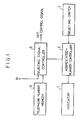
- the inventive telephone equipment shown in Fig.l features to include a telephone number memory 9 which stores telephone numbers and relations between the telephone numbers and corresponding abbreviated numbers, an indicator 7 for displaying the abbreviated numbers, a selecting switch 1 for scanning the abbreviated numbers and selecting a specific abbreviated number, an abbreviated number controller 3 which drives the indicator 7 to display abbreviated numbers sequentially in response to the operation of the selecting switch 1, a selecting signal controller 5 which retrieves a telephone number corresponding to a displayed abbreviated number from the telephone number, memory 9 and controls an output of a selecting signal corresponding to the retrieved telephone number on receiving a signal determining a transmission start of the selecting signal.
- a telephone number memory 9 which stores telephone numbers and relations between the telephone numbers and corresponding abbreviated numbers
- an indicator 7 for displaying the abbreviated numbers
- a selecting switch 1 for scanning the abbreviated numbers and selecting a specific abbreviated number
- an abbreviated number controller 3 which drives the indicator 7 to display ab
- the inventive telephone equipment are not limited, but it can be installed in vehicles such as automobiles, boats and aircrafts, and in buildings as well.
- the above-mentioned selecting switch 1 and indicator 7 may be disposed in arbitrary locations, or they are preferably integrated on the handset together with a speaker, microphone and push button, etc., thereby to realize a useful and compact telephone equipment.
- the handset may be connected with the main unit either through a cable or the radio.
- the selecting switch 1 is a switch for producing a binary ON/OFF signal.
- the abbreviated number controller 3 displays updating abbreviated numbers sequentially on the indicator 7 in response to operation of the selecting switch 1, in such a way of updating the number each time the selecting switch 1 is ' pressed, or updating the number sequentially while the selecting switch 1 is kept pressed, or updating the number sequentially by the first press of the switch 1 and halting the number scan and selecting the current number by the second press.
- the telephone number memory 9 stores called party's telephone number in correspondence to abbreviated numbers.
- the selecting signal controller 5 retrieves a currently intended telephone number of a called party correspond to the abbreviated number displayed on the indicator 7 and receives a signal for determining a transmission start of a selecting signal and then outputs a signal which controls an output of the selecting signal.
- the signal for determining the transmission start of the selecting signal can be inputted by means of a switch which outputs hook-signal or by an operation state of the selecting switch 1.
- the function of the selecting switch 1 can be determined by duration of press, i.e., the long time depression of the selecting switch 1 generates the signal for determining a transmission start of a selecting signal while short time depression of the switch 1 provides the selection of the abbreviated number.
- the telephone equipment of the present invention can be implemented with an additional function to renew memory to restore new telephone numbers in correspondence to abbreviated numbers and displays the renewed telephone numbers.
- the operation to make a telephone call the user searches the memory for the intended telephone number using the selecting switch 1 which displays the abbreviated numbers sequentially on the indicator 7.
- the selecting signal controller 5 receives a signal which controls the transmission start of the selecting signal by use of the selecting switch 1 or other switches.
- the selecting signal controller 5 retrieves a certain telephone number of a called party accordingly and outputs a control signal in correspondence to the searched telephone number. Consequently the selecting signal is send to a base telephone station and then a ring signal is received at the called party.
- a selecting switch 138 for producing a binary ON/OFF signal for producing a binary ON/OFF signal
- a microphone 136 for producing a binary ON/OFF signal
- a numeric indicator 139 for producing a binary ON/OFF signal
- a speaker 137 for producing a talk switch 134 for producing an off-hook and on-hook signals used to initiate and terminate a call.
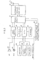
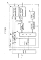
- Fig.3 shows a block diagram of the electrical arrangement of the embodiment which is connected to an automobile-installed main unit 90.
- the main unit 90 links with the base telephone station through the radio for transmitting the initiation signal or termination signal in response to the off-hook or on-hook operation of the handset, transmitting a telephone number signal of a called party, and receiving a ring signal from the base telephone station.
- a branch circuit 91 is provided, allowing the selective use of the conventional mobile telephone equipment 92 connected in parallel to the inventive telephone equipment.
- An audio switch 80 is used to avoid the howlihg when the inventive equipment is operated in loud-speech mode.
- the principal portion of this embodiment is implemented by a computer system, in which-a CPU 32 is connected with the indicator 139, selecting switch138, talk switch 134 and keyboard 133.
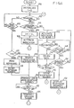
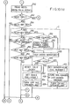
- Fig.4 is a flowchart showing the computer processing program adapted to this embodiment.
- the CPU 32 commences the execution of the program at step 100.
- step 100 the initial values are set up for the system.
- Operating parameter I represents the abbreviated number ranging from 1 through 9, with number 0 indicating the unspecified state of the abbreviated number.
- the program sequence proceeds to step 102, in which it is tested as to whether the selecting switch 138 has been operated. If the operation of the switch 138 is sensed, the duration of operation is compared with the preset time length To in step 104 and, if the duration is shorter than To, the sequence proceeds to step 106.
- Step 106 increments the value of I by 1, and activates the indicator 139 to display the abbreviated number.
- step 120 in which the state of the talk switch 134 is sensed, and it returns to step 102 if the switch 134 is off.
- the abbreviated number is scanned in step 106 and it is displayed on the indicator. Accordingly, through the iterative operation of the loop including steps 102-108, a desired abbreviated number is selected by the user.
- the value of I when reaches 10, is reset to ç and incremented sequentially in response to each short-period operation of the selecting switch 138.
- This operating loop 102-108 implements the function of the abbreviated number controller mentioned previously.
- step 120 In response to the operation of the talk switch 134 following the selection of an abbreviated number, the sequence proceeds from step 120 to step 122. Unless I equals to 0, the sequence goes to step 128, in which the telephone number memory 9 is addressed in accordance with the value of I so as to retrieve a corresponding telephone number.
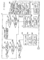
- step 130 the control signal is issued to the main unit 90 so that the call initiation signal and the selected telephone number are transmitted.
- the step of 120 to 130 implements the function of the selecting signal controller previously described.
- the signal transmission is acknowledged by a ring signal sounded by the speaker 137, and communication is established when the called party lifts the handset.
- the communication is terminated by the operation of the talk switch 134.
- step 132 tests as to whether the talk switch 134 is operated, and in response to the detection the on-hook signal is issued to the main unit 90.
- step 122 the abbreviated numbers are scanned to select a specific number, which retrieves the telephone number of the selected called party so that the telephone communication is established.
- the parameter I of 0 in step 122 signifies that no abbreviated number is selected and in this case the sequence proceeds to step 124 in which the formal telephone number is entered through the keyboard 133 as in the usual dialing operation.
- step 104 if the selecting switch 138 is determined to have been pressed longer than the specified time length, the sequence proceeds to step 140.
- step 140 the selected abbreviated number I is displayed by blinking on the indicator 139 thereby to draw user's attention.
- step 144 the system makes a transition of function to receive a formal telephone number.
- step 146 the telephone number entered in step 144 is stored in the telephone number memory 9 in correspondence to the abbreviated number I.
- step 148 in which it is tested as to whether the selecting switch 138 is operated.
- steps 142 and 148 are executed repeatedly.
- the sequence proceeds to step 152.
- step 152 the formal telephone numbers corresponding to the abbreviated numbers are displayed sequentially on the indicator 139. These operations are repeated and finally the sequence returns to step 102.
- step 150 if the selecting switch 138 is determined to have been pressed longer than the specified time length, the sequence goes to step 140 so as to implement the selection of the decision from the beginning. This allows the user, when made a mistake in entering data in step 144, to reenter a correct telephone number from the beginning by operating the selecting switch 138.
- This embodiment is intended to apply to a mobile telephone system equipped in an automobile, and the telephone handset with integration of functions is held detachably in the pad of the steering wheel.
- the handset links by the FM radio with the mobile main unit which performs transmission and reception between the automobile and the ground base station.
- Fig.5 is a perspective view showing the arrangement of this embodiment.
- a steering wheel 10 is made up of a ring handle 11 and a pad 12.
- the pad 12 is designed to hold a handset 13 detachably.
- the handset 13 is taken out of the pad 12 by operating the eject button 121.
- Figs.6 and 7 are perspective views showing the back and front of the handset 13, respectively.
- the handset 13 includes-on its backside a microphone 131, a speaker 132 used in closed-speech mode, a calling push button key set 133, a speech control talk switch 134, and a hook switch 135.
- the handset 13 includes on its front side a voice collection port 136 at the microphone 131 used in loud-speech mode, a speaker 137 used in loud-speech mode, a selecting switch 138 used to retrieve called party's telephone numbers which have been memorized in advance, and an indicator 139 for displaying an abbreviated number of a called party.
- the inventive telephone equipment allows the automobile driver to make a telephone call in loud-speech mode during a run, with the handset 13 held in the pad 12, by specifying a called party through the scanning of the stored telephone numbers using the selecting switch 138.
- the equipment also allows the normal usage in closed-speech mode when the handset 13 is taken out of the pad 12, by dialing a telephone number on the push buttons 133 or by use of the selecting switch 138.
- Fig.8 shows in block diagram the circuit arrangement provided in the pad 12 and handset 13, and Fig.9 shows the circuit arrangement of the relay unit installed in the user's automobile.
- Control within the handset 13 is implemented by a CPU (Central Processing Unit) 32, which is in connection with a push button key set 133 (TEN KEYS), selecting switch 138, hook switch 135 and talk switch 134.
- the control signals produced by these operating switches are processed by the CPU 32, and after being frequency-modulated by a modem 42, delivered to an FM stereo transmitter 36.
- a microphone switch circuit 44 selects the audio signal from the microphone 131 and delivers it through an amplifier 46 to the FM stereo transmitter 36.
- the control signals are in the right channel and audio signals are in the left channel, and these FM radio waves transmitted by the transmitter 36 are received by an FM stereo receiver 78 in the relay unit.
- the FM radio waves transmitted by an FM stereo transmitter 76 in the relay unit are received by an FM stereo receiver 34, and the audio signal is delivered through a speaker switch circuit 38 to the speaker 132 in closed-speech mode, or to the speaker 137 via an amplifier 40 in loud-speech mode.
- the circuitry within the handset 13 is powered by the vehicle-installed battery through a voltage regulator 58 provided in the pad 12 when the handset 13 is held in the pad 12.
- the battery is also used to charge a rechargeable cell 60 in the handset 13 through a charging circuit 56 provided in the pad 12.
- an off-pad detection circuit 54 operates on a power switch change circuit 52 through the CPU 32, and the handset 13 is powered by the rechargeable cell 60.
- the voltages supplied by these power sources are converted into several voltages by a voltage regulator 53.
- the relay unit incorporates a main unit interface 72, a CPU 70, an FM stereo transmitter 76, an FM stereo receiver 78, a modem 74 and an audio switch 80.
- the audio signal is delivered through the audio switch 80 to the audio signal input terminal of the main unit 90, while the control signal encoded by the modem 74 is fed to the CPU 70 and after being processed delivered through the main unit interface 72 to the control input signal terminal of the main unit 90.
- the CPU 32 selects the speaker 137 and activates both of the microphone 131 and the microphone 140 installed in the pad 12 so as to form a gradient microphone for the speech operation in loud-speech mode.
- the CPU 32 has memorized the state of the talk switch 134, and sends the off-hook signal or on-hook signal depending on the switch position to the CPU 70 in the relay unit, then the CPU 70 sends the off-hook signal or on-hook signal to the main unit 90, which in turn transmits the initiation signal or termination signal to the base station to connect or release the telephone network.
- the user operates the selecting switch 138 to read out the preset abbreviated numbers on the indicator 139.
- the CPU 32 sends the telephone number corresponding to the abbreviated number to the main unit 90 via the CPU 70 in response to the operation of the talk switch 134.
- the main unit 90 transmits the telephone number to the base station, which then rings the called party through the exchange and network and, at the same time, issues a ring signal to the mobile main unit 90 with the result of a ring emitted by the speaker 137.
- the called party responds to the ring, the connection is established between both parties through the network.
- the CPU 32 issues the on-hook signal and the main unit 90 transmits the termination signal to shut down the line connection.
- the talk switch 134 functions identically to the hook switch equipped in the usual telephone set.
- the operation is closed-speech mode will be described.
- the off-pad detection circuit 54 issues the signal to the CPU 32, which then selects the microphone 131 and speaker 132.
- the ring signal is sounded by the speaker 137.
- the same operating procedures are used to respond to an incoming call and to make calling.
- a call can be made also by dialing a formal telephone number of a called party by use of the hook switch 135 and push button key set 133.
- the user operates the talk switch 134, and the on-hook signal is produced so that the main unit 90 transmits the termination signal.
- Figs.10 (a), 10(b), 10(c), 10(d) and 10(e) are flowcharts showing the processings of the CPU 32 accommodated within the handset.
- Part A including steps 202 through 216 is a processing routine dealing with the operation against power voltage variation.
- the handset 13 is supplied with power from the vehicle battery when it is held in the pad 12, or from its own rechargeable cell when it is taken out of the pad 12. If the voltage of the rechargeable cell falls below a certain level, an external interrupt is generated so that the CPU halts the processing.
- Part B including steps 220 through 230 is a processing routine specific to the mobile communication, dealing with the operation of the case when the vehicle has gone out of the service area of the base station.
- a routine including steps 240 through 258 reads the states of the operating keys.
- a routine of part C including steps 246, 260 and 262 counts time in which the selecting switch 138 (SCAN SWITCH) is depressed.
- Part D including steps 264 through 272 is to evaluate the time length of depressing of the switch 138,
- Part E including steps 274 through 280 selects an abbreviated number through the incrementing . operation, and reads out the selected number on the indicator.
- Part F including steps 340 through 344 is to display stored telephone numbers sequentially during the scanning operation. The routine F is initiated when the selecting switch is operated for at least the specified duration and then. operated again for a duration less than the specified time length.
- Part J including steps 258 and 302-310 is a processing routine for fetching a telephone number from the keyboard in correspondence to the . selected abbreviated number and storing the telephone number. This routine is initiated when the selecting switch is operated for at least the specified duration and then the keyboard is operated.
- the inventive telephone equipment allows the calling of a called party by scanning the abbreviated numbers and also displaying and memorizing corresponding telephone numbers.
- Part G including steps 500 through 510 is the transmission process for the operation using the hook switch 135 and push button set 133.
- the last digit of the calling number is memorized so as to allow a simple re-calling with the talk switch 134 when character "L" is displayed on the indicator 139.
- Part H including steps 410 through 416 selects the loud-speech mode or closed-speech mode depending on the presence or absence of the handset in the pad.
- Part I including steps 418 through 426 is a processing routine for sending the signal to the computer within the relay unit in correspondence to the selected telephone number.
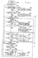
- Fig.11 is a flowchart showing the processing of the CPU 70 within the relay unit.
- Steps 602 and 604 are for the process when the vehicle has gone out of the service area.
- Steps 606 and 608 deal with incoming call.
- Part M including steps 650 through 660 is a routine for sending a telephone number from the handset to the main unit.
- step 658 produces the off-hook signal and step 660 outputs the telephone number.
- Part K including steps 670 through 676 is a routine for sending the on-hook or off-hook signal to the main unit depending on the state of the talk switch.
- Part L including steps 680 through 688 is a routine for outputting data to the handset in response to the reception of an incoming call by the mobile equipment main unit.
- the present invention is embodied by the foregoing circuit arrangement and its operation.
Abstract
Description
- The present invention relates to a telephone equipment with enhanced operability and, particularly, to a telephone equipment which enables the user to make a call through a reduced number of key operations and is also capable of memorizing telephone numbers of called parties and displaying abbreviated numbers corresponding to the telephone numbers. The telephone equipment of the present invention is particularly useful as a mobile telephone equipment operated by the vehicle driver.
- With the recent advanced mobile telephone communications network, there is an increasing demand of installing the telephone equipment on vehicles, particularly, automobiles. However, the conventional mobile telephone equipment is of the same type as used indoors, and a special situation of usage on a vehicle is not taken into account. For example, the automobile driver receives a call and also makes a call during a drive. However, the indoor-type telephone set bothers the driver in dialing a telephone number, and it is often impractical to have a calling operation during a run, even if abbreviated numbers which are registered to a base telephone station are used.
- The present invention contemplates to overcome the foregoing prior art deficiency, and its prime object is to provide a telephone equipment with enhanced operability.
- In order to achieve the above objective, the inventive telephone equipment shown in Fig.l features to include a
telephone number memory 9 which stores telephone numbers and relations between the telephone numbers and corresponding abbreviated numbers, anindicator 7 for displaying the abbreviated numbers, a selectingswitch 1 for scanning the abbreviated numbers and selecting a specific abbreviated number, an abbreviatednumber controller 3 which drives theindicator 7 to display abbreviated numbers sequentially in response to the operation of the selectingswitch 1, a selectingsignal controller 5 which retrieves a telephone number corresponding to a displayed abbreviated number from the telephone number,memory 9 and controls an output of a selecting signal corresponding to the retrieved telephone number on receiving a signal determining a transmission start of the selecting signal. - Uses of the inventive telephone equipment are not limited, but it can be installed in vehicles such as automobiles, boats and aircrafts, and in buildings as well. The above-mentioned
selecting switch 1 andindicator 7 may be disposed in arbitrary locations, or they are preferably integrated on the handset together with a speaker, microphone and push button, etc., thereby to realize a useful and compact telephone equipment. The handset may be connected with the main unit either through a cable or the radio. The selectingswitch 1 is a switch for producing a binary ON/OFF signal. The abbreviatednumber controller 3 displays updating abbreviated numbers sequentially on theindicator 7 in response to operation of the selectingswitch 1, in such a way of updating the number each time the selectingswitch 1 is 'pressed, or updating the number sequentially while the selectingswitch 1 is kept pressed, or updating the number sequentially by the first press of theswitch 1 and halting the number scan and selecting the current number by the second press. Thetelephone number memory 9 stores called party's telephone number in correspondence to abbreviated numbers. The selectingsignal controller 5 retrieves a currently intended telephone number of a called party correspond to the abbreviated number displayed on theindicator 7 and receives a signal for determining a transmission start of a selecting signal and then outputs a signal which controls an output of the selecting signal. The signal for determining the transmission start of the selecting signal can be inputted by means of a switch which outputs hook-signal or by an operation state of the selectingswitch 1. For example, the function of the selectingswitch 1 can be determined by duration of press, i.e., the long time depression of the selectingswitch 1 generates the signal for determining a transmission start of a selecting signal while short time depression of theswitch 1 provides the selection of the abbreviated number. Additionally, the telephone equipment of the present invention can be implemented with an additional function to renew memory to restore new telephone numbers in correspondence to abbreviated numbers and displays the renewed telephone numbers. - The operation to make a telephone call, the user searches the memory for the intended telephone number using the selecting
switch 1 which displays the abbreviated numbers sequentially on theindicator 7. Next, the selectingsignal controller 5 receives a signal which controls the transmission start of the selecting signal by use of the selectingswitch 1 or other switches. The selectingsignal controller 5 retrieves a certain telephone number of a called party accordingly and outputs a control signal in correspondence to the searched telephone number. Consequently the selecting signal is send to a base telephone station and then a ring signal is received at the called party. -
- Fig.l is a block diagram showing the general arrangement of the inventive telephone equipment;
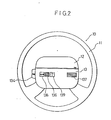
- Fig.2 is a plan view showing the operating panel of the telephone equipment embodying the present invention;
- Fig.3 is a block diagram showing the electrical arrangement of the above embodiment;
- Fig.4. is a flowchart showing the computer processing implemented in the above embodiment;
- Fig.5 is an illustration showing the telephone equipment according to another embodiment of this invention;
- Figs.6 and 7 are perspective views showing the handset of this embodiment;
- Figs.8 and 9 are block diagrams showing the electrical arrangement of the above embodiment; and
- Figs.10(a), 10(b), 10(c), 10(d), 10(e) and 11 are flowcharts showing the computer processing implemented in the above embodiment.
- An embodiment of this invention will be described in more detail.
- In Fig.2 showing the operating panel of the inventive telephone equipment installed on the steering wheel pad of an automobile, there are provided in a
pad 12 of asteering wheel 10, a selectingswitch 138 for producing a binary ON/OFF signal, amicrophone 136, anumeric indicator 139, aspeaker 137, and atalk switch 134 for producing an off-hook and on-hook signals used to initiate and terminate a call. - Fig.3 shows a block diagram of the electrical arrangement of the embodiment which is connected to an automobile-installed
main unit 90. Themain unit 90 links with the base telephone station through the radio for transmitting the initiation signal or termination signal in response to the off-hook or on-hook operation of the handset, transmitting a telephone number signal of a called party, and receiving a ring signal from the base telephone station. - A
branch circuit 91 is provided, allowing the selective use of the conventionalmobile telephone equipment 92 connected in parallel to the inventive telephone equipment. Anaudio switch 80 is used to avoid the howlihg when the inventive equipment is operated in loud-speech mode. - The principal portion of this embodiment is implemented by a computer system, in which-a
CPU 32 is connected with theindicator 139, selecting switch138,talk switch 134 andkeyboard 133. - Fig.4 is a flowchart showing the computer processing program adapted to this embodiment. The
CPU 32 commences the execution of the program atstep 100. Instep 100, the initial values are set up for the system. Operating parameter I represents the abbreviated number ranging from 1 through 9, withnumber 0 indicating the unspecified state of the abbreviated number. The program sequence proceeds tostep 102, in which it is tested as to whether the selectingswitch 138 has been operated. If the operation of theswitch 138 is sensed, the duration of operation is compared with the preset time length To instep 104 and, if the duration is shorter than To, the sequence proceeds tostep 106. Namely, a shorter operation of the selectingswitch 138 causes the decision circuit to recognize it as the first decision result, which sets up the system function to select an abbreviated number.Step 106 increments the value of I by 1, and activates theindicator 139 to display the abbreviated number. - The sequence proceeds to
step 120, in which the state of thetalk switch 134 is sensed, and it returns tostep 102 if theswitch 134 is off. Namely, depending on the number of operations of the selectingswitch 138, the abbreviated number is scanned instep 106 and it is displayed on the indicator. Accordingly, through the iterative operation of the loop including steps 102-108, a desired abbreviated number is selected by the user. The value of I, when reaches 10, is reset to ç and incremented sequentially in response to each short-period operation of the selectingswitch 138. This operating loop 102-108 implements the function of the abbreviated number controller mentioned previously. - In response to the operation of the
talk switch 134 following the selection of an abbreviated number, the sequence proceeds fromstep 120 tostep 122. Unless I equals to 0, the sequence goes tostep 128, in which thetelephone number memory 9 is addressed in accordance with the value of I so as to retrieve a corresponding telephone number. - In the
subsequent step 130, the control signal is issued to themain unit 90 so that the call initiation signal and the selected telephone number are transmitted. The step of 120 to 130 implements the function of the selecting signal controller previously described. The signal transmission is acknowledged by a ring signal sounded by thespeaker 137, and communication is established when the called party lifts the handset. The communication is terminated by the operation of thetalk switch 134. Namely,step 132 tests as to whether thetalk switch 134 is operated, and in response to the detection the on-hook signal is issued to themain unit 90. - In this way, the abbreviated numbers are scanned to select a specific number, which retrieves the telephone number of the selected called party so that the telephone communication is established. The parameter I of 0 in
step 122 signifies that no abbreviated number is selected and in this case the sequence proceeds tostep 124 in which the formal telephone number is entered through thekeyboard 133 as in the usual dialing operation. - In the
next step 104, if theselecting switch 138 is determined to have been pressed longer than the specified time length, the sequence proceeds tostep 140. Instep 140, the selected abbreviated number I is displayed by blinking on theindicator 139 thereby to draw user's attention. Subsequently, if there is akeyboard 133 input, the sequence proceeds to step 144. In this case, the system makes a transition of function to receive a formal telephone number. Instep 146, the telephone number entered instep 144 is stored in thetelephone number memory 9 in correspondence to the abbreviated number I. In another case when there is no keyboard entry instep 142, the sequence goes to step 148, in which it is tested as to whether the selectingswitch 138 is operated. If switch operation is not sensed,steps switch 138 has been pressed shorter than the specified time length, the sequence proceeds to step 152. Instep 152, the formal telephone numbers corresponding to the abbreviated numbers are displayed sequentially on theindicator 139. These operations are repeated and finally the sequence returns to step 102. Instep 150, if the selectingswitch 138 is determined to have been pressed longer than the specified time length, the sequence goes to step 140 so as to implement the selection of the decision from the beginning. This allows the user, when made a mistake in entering data instep 144, to reenter a correct telephone number from the beginning by operating the selectingswitch 138. - Through the above operations, formal telephone numbers can be memorized in correspondence to abbreviated numbers, and each stored telephone number can be read out on the 1-
digit indicator 139 on a digit- by-digit basis. It is also possible to scan abbreviated numbers to select one and make a call through the automatic search for the telephone number corresponding to the selected abbreviated number. - Next, the second embodiment of this invention will be described. This embodiment is intended to apply to a mobile telephone system equipped in an automobile, and the telephone handset with integration of functions is held detachably in the pad of the steering wheel. The handset links by the FM radio with the mobile main unit which performs transmission and reception between the automobile and the ground base station.
- Fig.5 is a perspective view showing the arrangement of this embodiment. A
steering wheel 10 is made up of aring handle 11 and apad 12. Thepad 12 is designed to hold ahandset 13 detachably. Thehandset 13 is taken out of thepad 12 by operating theeject button 121. Figs.6 and 7 are perspective views showing the back and front of thehandset 13, respectively. Thehandset 13 includes-on its backside amicrophone 131, aspeaker 132 used in closed-speech mode, a calling push button key set 133, a speechcontrol talk switch 134, and ahook switch 135. Thehandset 13 includes on its front side avoice collection port 136 at themicrophone 131 used in loud-speech mode, aspeaker 137 used in loud-speech mode, a selectingswitch 138 used to retrieve called party's telephone numbers which have been memorized in advance, and anindicator 139 for displaying an abbreviated number of a called party. - The inventive telephone equipment allows the automobile driver to make a telephone call in loud-speech mode during a run, with the
handset 13 held in thepad 12, by specifying a called party through the scanning of the stored telephone numbers using the selectingswitch 138. The equipment also allows the normal usage in closed-speech mode when thehandset 13 is taken out of thepad 12, by dialing a telephone number on thepush buttons 133 or by use of the selectingswitch 138. - Fig.8 shows in block diagram the circuit arrangement provided in the
pad 12 andhandset 13, and Fig.9 shows the circuit arrangement of the relay unit installed in the user's automobile. Control within thehandset 13 is implemented by a CPU (Central Processing Unit) 32, which is in connection with a push button key set 133 (TEN KEYS), selectingswitch 138,hook switch 135 and talkswitch 134. The control signals produced by these operating switches are processed by theCPU 32, and after being frequency-modulated by amodem 42, delivered to anFM stereo transmitter 36. - In closed-speech mode, a
microphone switch circuit 44 selects the audio signal from themicrophone 131 and delivers it through anamplifier 46 to theFM stereo transmitter 36. The control signals are in the right channel and audio signals are in the left channel, and these FM radio waves transmitted by thetransmitter 36 are received by anFM stereo receiver 78 in the relay unit. - The FM radio waves transmitted by an
FM stereo transmitter 76 in the relay unit are received by anFM stereo receiver 34, and the audio signal is delivered through aspeaker switch circuit 38 to thespeaker 132 in closed-speech mode, or to thespeaker 137 via anamplifier 40 in loud-speech mode. - The circuitry within the
handset 13 is powered by the vehicle-installed battery through avoltage regulator 58 provided in thepad 12 when thehandset 13 is held in thepad 12. The battery is also used to charge arechargeable cell 60 in thehandset 13 through a chargingcircuit 56 provided in thepad 12. When thehandset 13 is taken out of thepad 12, an off-pad detection circuit 54 operates on a powerswitch change circuit 52 through theCPU 32, and thehandset 13 is powered by therechargeable cell 60. The voltages supplied by these power sources are converted into several voltages by avoltage regulator 53. - The relay unit incorporates a
main unit interface 72, aCPU 70, anFM stereo transmitter 76, anFM stereo receiver 78, amodem 74 and anaudio switch 80. Among the FM radio waves received by theFM stereo receiver 78, the audio signal is delivered through theaudio switch 80 to the audio signal input terminal of themain unit 90, while the control signal encoded by themodem 74 is fed to theCPU 70 and after being processed delivered through themain unit interface 72 to the control input signal terminal of themain unit 90. - When the off-
pad detection circuit 54 in thehandset 13 detects that thehandset 13 is held in thepad 12, theCPU 32 selects thespeaker 137 and activates both of themicrophone 131 and themicrophone 140 installed in thepad 12 so as to form a gradient microphone for the speech operation in loud-speech mode. - In this state, when the system receives an incoming call, a ring is sounded by the
speaker 137. Then, the user talks in loud-speech mode by operating thetalk switch 134. On completion of communication, thetalk switch 134 is operated again so that the system is removed from the telephone network. In more detail, theCPU 32 has memorized the state of thetalk switch 134, and sends the off-hook signal or on-hook signal depending on the switch position to theCPU 70 in the relay unit, then theCPU 70 sends the off-hook signal or on-hook signal to themain unit 90, which in turn transmits the initiation signal or termination signal to the base station to connect or release the telephone network. - To make a call, the user operates the selecting
switch 138 to read out the preset abbreviated numbers on theindicator 139. Upon selection of a called party's number, theCPU 32 sends the telephone number corresponding to the abbreviated number to themain unit 90 via theCPU 70 in response to the operation of thetalk switch 134. Themain unit 90 transmits the telephone number to the base station, which then rings the called party through the exchange and network and, at the same time, issues a ring signal to the mobilemain unit 90 with the result of a ring emitted by thespeaker 137. When the called party responds to the ring, the connection is established between both parties through the network. In response to the operation of thetalk switch 134 upon termination of communication, theCPU 32 issues the on-hook signal and themain unit 90 transmits the termination signal to shut down the line connection. As will be appreciated, thetalk switch 134 functions identically to the hook switch equipped in the usual telephone set. - Next, the operation is closed-speech mode will be described. When the
handset 13 is taken out of thepad 12, the off-pad detection circuit 54 issues the signal to theCPU 32, which then selects themicrophone 131 andspeaker 132. The ring signal is sounded by thespeaker 137. The same operating procedures are used to respond to an incoming call and to make calling. In this mode, a call can be made also by dialing a formal telephone number of a called party by use of thehook switch 135 and push button key set 133. To terminate a call, the user operates thetalk switch 134, and the on-hook signal is produced so that themain unit 90 transmits the termination signal. - Figs.10 (a), 10(b), 10(c), 10(d) and 10(e) are flowcharts showing the processings of the
CPU 32 accommodated within the handset. PartA including steps 202 through 216 is a processing routine dealing with the operation against power voltage variation. As mentioned previously, thehandset 13 is supplied with power from the vehicle battery when it is held in thepad 12, or from its own rechargeable cell when it is taken out of thepad 12. If the voltage of the rechargeable cell falls below a certain level, an external interrupt is generated so that the CPU halts the processing. - Part
B including steps 220 through 230 is a processing routine specific to the mobile communication, dealing with the operation of the case when the vehicle has gone out of the service area of the base station. - A
routine including steps 240 through 258 reads the states of the operating keys. A routine of partC including steps D including steps 264 through 272 is to evaluate the time length of depressing of theswitch 138, PartE including steps 274 through 280 selects an abbreviated number through the incrementing . operation, and reads out the selected number on the indicator. PartF including steps 340 through 344 is to display stored telephone numbers sequentially during the scanning operation. The routine F is initiated when the selecting switch is operated for at least the specified duration and then. operated again for a duration less than the specified time length. - Part
J including steps 258 and 302-310 is a processing routine for fetching a telephone number from the keyboard in correspondence to the . selected abbreviated number and storing the telephone number. This routine is initiated when the selecting switch is operated for at least the specified duration and then the keyboard is operated. - Through these operating steps, the inventive telephone equipment allows the calling of a called party by scanning the abbreviated numbers and also displaying and memorizing corresponding telephone numbers.
- Part
G including steps 500 through 510 is the transmission process for the operation using thehook switch 135 and push button set 133. The last digit of the calling number is memorized so as to allow a simple re-calling with thetalk switch 134 when character "L" is displayed on theindicator 139. PartH including steps 410 through 416 selects the loud-speech mode or closed-speech mode depending on the presence or absence of the handset in the pad. Part I includingsteps 418 through 426 is a processing routine for sending the signal to the computer within the relay unit in correspondence to the selected telephone number. - Fig.11 is a flowchart showing the processing of the
CPU 70 within the relay unit.Steps Steps M including steps 650 through 660 is a routine for sending a telephone number from the handset to the main unit. When the talk switch is operated as sensed in step 656,step 658 produces the off-hook signal and step 660 outputs the telephone number. PartK including steps 670 through 676 is a routine for sending the on-hook or off-hook signal to the main unit depending on the state of the talk switch. PartL including steps 680 through 688 is a routine for outputting data to the handset in response to the reception of an incoming call by the mobile equipment main unit. - The present invention is embodied by the foregoing circuit arrangement and its operation.
Claims (4)
Applications Claiming Priority (2)
| Application Number | Priority Date | Filing Date | Title |
|---|---|---|---|
| JP59204988A JPS6182560A (en) | 1984-09-28 | 1984-09-28 | Telephone device |
| JP204988/84 | 1984-09-28 |
Publications (3)
| Publication Number | Publication Date |
|---|---|
| EP0176104A2 true EP0176104A2 (en) | 1986-04-02 |
| EP0176104A3 EP0176104A3 (en) | 1988-09-07 |
| EP0176104B1 EP0176104B1 (en) | 1990-12-19 |
Family
ID=16499613
Family Applications (1)
| Application Number | Title | Priority Date | Filing Date |
|---|---|---|---|
| EP85112290A Expired - Lifetime EP0176104B1 (en) | 1984-09-28 | 1985-09-27 | Telephone equipment |
Country Status (4)
| Country | Link |
|---|---|
| US (1) | US4723265A (en) |
| EP (1) | EP0176104B1 (en) |
| JP (1) | JPS6182560A (en) |
| DE (1) | DE3580958D1 (en) |
Cited By (8)
| Publication number | Priority date | Publication date | Assignee | Title |
|---|---|---|---|---|
| FR2613562A1 (en) * | 1987-04-06 | 1988-10-07 | Setsys Engineering Telecommuni | Portable radio telephone with detachable handset |
| AU601322B1 (en) * | 1989-03-28 | 1990-09-06 | Samsung Electronics Co., Ltd. | Direct telephone-number selecting system |
| USRE33417E (en) * | 1986-10-27 | 1990-10-30 | Mobile Telecommunication Technologies Corporation | Mobile paging call back system and related method |
| EP0423733A2 (en) * | 1989-10-19 | 1991-04-24 | Siemens Aktiengesellschaft Österreich | Support device for the mobile unit of a cordless or mobile telephone |
| US5095503A (en) * | 1989-12-20 | 1992-03-10 | Motorola, Inc. | Cellular telephone controller with synthesized voice feedback for directory number confirmation and call status |
| AU639238B2 (en) * | 1989-06-09 | 1993-07-22 | Nec Corporation | Apparatus for referring to a content of a dial memory in a telephone set |
| US5276729A (en) * | 1990-09-10 | 1994-01-04 | Oki Telecom | Radiotelephone for automatically dialing remotely programmed number upon call termination and without user operation |
| US6052581A (en) * | 1994-07-26 | 2000-04-18 | Nokia Mobile Phones Limited | Automatic NAM programming of radio telephone |
Families Citing this family (19)
| Publication number | Priority date | Publication date | Assignee | Title |
|---|---|---|---|---|
| JPS6359123A (en) * | 1986-08-29 | 1988-03-15 | Toshiba Corp | Howler display device for cordless telephone system |
| US6167278A (en) * | 1986-10-22 | 2000-12-26 | Nilssen; Ole K. | Combination cordless-cellular telephone system |
| JPS63233638A (en) * | 1987-03-21 | 1988-09-29 | Aisin Seiki Co Ltd | Vehicle telephone system |
| JPS63246063A (en) * | 1987-03-31 | 1988-10-13 | Aisin Seiki Co Ltd | Telephone set |
| US5127040A (en) * | 1987-06-02 | 1992-06-30 | Motorola, Inc. | Radiotelephone telephone number down loading |
| CA1316617C (en) * | 1988-07-11 | 1993-04-20 | Chihiro Fuse | Telephone |
| JPH0243855A (en) * | 1988-08-04 | 1990-02-14 | Toshiba Corp | Radio telephone set |
| US5247572A (en) * | 1989-07-24 | 1993-09-21 | Nec Corporation | Apparatus for control of storing information into dial memories in a telephone set |
| EP0437380B1 (en) * | 1990-01-12 | 1999-03-24 | Sony Corporation | Cordless telephone |
| US5491745A (en) * | 1991-02-20 | 1996-02-13 | Uniden America Corporation | Method and apparatus for a dual mode keypad permitting one-touch telephone number dialing |
| DK170904B1 (en) * | 1992-08-18 | 1996-03-04 | Dancall Telecom As | Mobile phone with support arm for control unit thereto |
| US5917904A (en) * | 1995-05-12 | 1999-06-29 | Illinois Technology Transfer, Llc | Automatic area code detector and dialer |
| DE19624635B4 (en) * | 1996-06-21 | 2004-04-29 | Robert Bosch Gmbh | Radio receiver |
| JP3318927B2 (en) * | 1999-02-16 | 2002-08-26 | 日本電気株式会社 | Operating method of mobile phone and operating device thereof |
| US6397086B1 (en) * | 1999-06-22 | 2002-05-28 | E-Lead Electronic Co., Ltd. | Hand-free operator capable of infrared controlling a vehicle's audio stereo system |
| US7233808B2 (en) * | 2001-09-05 | 2007-06-19 | Agere Systems Inc. | Smart BLUETOOTH interface gateway to mate a non-BLUETOOTH wireless device with a BLUETOOTH headset |
| US7706832B2 (en) * | 2005-05-20 | 2010-04-27 | Kyocera Wireless Corp. | Systems and methods for using aliases to manage contact information in a mobile communication device |
| US7734315B2 (en) * | 2005-06-17 | 2010-06-08 | Rathus Spencer A | Wireless communication device management |
| US8923931B2 (en) | 2005-06-17 | 2014-12-30 | Marshall Feature Recognition Llc | Wireless communication device management |
Citations (4)
| Publication number | Priority date | Publication date | Assignee | Title |
|---|---|---|---|---|
| UST966005I4 (en) * | 1977-07-05 | 1978-01-03 | Bell Telephone Laboratories Incorporated | Repertory dialer |
| FR2437120A1 (en) * | 1978-09-21 | 1980-04-18 | Carso Electronic Instr Co | TELEPHONE APPARATUS HAVING ELECTRONIC DEVICE FOR AUTOMATIC SEARCHING AND CALLING OF STORED NUMBERS |
| JPS567537A (en) * | 1979-07-02 | 1981-01-26 | Nippon Telegr & Teleph Corp <Ntt> | Drive system for mobile radio telephone set |
| DE3242380A1 (en) * | 1981-11-25 | 1983-06-01 | Aisin Seiki K.K., Kariya, Aichi | TELEPHONE TRANSMISSION SYSTEM ON A ROAD VEHICLE |
Family Cites Families (11)
| Publication number | Priority date | Publication date | Assignee | Title |
|---|---|---|---|---|
| US3824465A (en) * | 1973-01-04 | 1974-07-16 | Int Mobile Machines | Portable tone decoder-encoder system |
| JPS541972B2 (en) * | 1974-12-05 | 1979-01-31 | ||
| US4181842A (en) * | 1976-09-13 | 1980-01-01 | Honeywell Inc. | D.C. monitoring circuit |
| FR2430146B1 (en) * | 1978-06-29 | 1986-05-09 | Stratel Sa | TELEPHONE AUTOMATIC CALL DEVICE |
| JPS55141838A (en) * | 1979-04-24 | 1980-11-06 | Fujitsu Ltd | Hand-free call unit for car telephone |
| JPS6049697B2 (en) * | 1979-06-15 | 1985-11-05 | 松下電器産業株式会社 | Method for manufacturing thin metal sheets |
| JPS58204663A (en) * | 1982-05-24 | 1983-11-29 | Yoshida Denki Kk | Retrieving device of telephone number |
| US4481382A (en) * | 1982-09-29 | 1984-11-06 | Villa Real Antony Euclid C | Programmable telephone system |
| JPS59146253A (en) * | 1983-02-09 | 1984-08-22 | Toyoda Gosei Co Ltd | Telephone transmitting and receiving device with abbreviated dial |
| US4581490A (en) * | 1983-12-22 | 1986-04-08 | Richard Genender | Wall telephone assembly |
| DE3410608A1 (en) * | 1984-03-22 | 1985-09-26 | Siemens AG, 1000 Berlin und 8000 München | Method for multiple use of the keys of the keypad of simple telephone stations |
-
1984
- 1984-09-28 JP JP59204988A patent/JPS6182560A/en active Pending
-
1985
- 1985-09-27 DE DE8585112290T patent/DE3580958D1/en not_active Expired - Lifetime
- 1985-09-27 EP EP85112290A patent/EP0176104B1/en not_active Expired - Lifetime
- 1985-09-27 US US06/780,847 patent/US4723265A/en not_active Expired - Fee Related
Patent Citations (4)
| Publication number | Priority date | Publication date | Assignee | Title |
|---|---|---|---|---|
| UST966005I4 (en) * | 1977-07-05 | 1978-01-03 | Bell Telephone Laboratories Incorporated | Repertory dialer |
| FR2437120A1 (en) * | 1978-09-21 | 1980-04-18 | Carso Electronic Instr Co | TELEPHONE APPARATUS HAVING ELECTRONIC DEVICE FOR AUTOMATIC SEARCHING AND CALLING OF STORED NUMBERS |
| JPS567537A (en) * | 1979-07-02 | 1981-01-26 | Nippon Telegr & Teleph Corp <Ntt> | Drive system for mobile radio telephone set |
| DE3242380A1 (en) * | 1981-11-25 | 1983-06-01 | Aisin Seiki K.K., Kariya, Aichi | TELEPHONE TRANSMISSION SYSTEM ON A ROAD VEHICLE |
Non-Patent Citations (2)
| Title |
|---|
| JAPAN TELECOMMUNICATIONS REVIEW, vol. 26, no. 3, July 1984, pages 195-199, Tokyo, JP; K. TSUJIMURA et al.: "Diverse automobile telephone services - hands-free telephone and coin telephone" * |
| PATENT ABSTRACTS OF JAPAN, vol. 5, no. 55 (E-52)[727], 16th April 1981; & JP-A-56 007 537 (NIPPON DENSHIN DENWA KOSHA) 26-01-1981 * |
Cited By (10)
| Publication number | Priority date | Publication date | Assignee | Title |
|---|---|---|---|---|
| USRE33417E (en) * | 1986-10-27 | 1990-10-30 | Mobile Telecommunication Technologies Corporation | Mobile paging call back system and related method |
| FR2613562A1 (en) * | 1987-04-06 | 1988-10-07 | Setsys Engineering Telecommuni | Portable radio telephone with detachable handset |
| AU601322B1 (en) * | 1989-03-28 | 1990-09-06 | Samsung Electronics Co., Ltd. | Direct telephone-number selecting system |
| AU639238B2 (en) * | 1989-06-09 | 1993-07-22 | Nec Corporation | Apparatus for referring to a content of a dial memory in a telephone set |
| EP0423733A2 (en) * | 1989-10-19 | 1991-04-24 | Siemens Aktiengesellschaft Österreich | Support device for the mobile unit of a cordless or mobile telephone |
| EP0423733A3 (en) * | 1989-10-19 | 1991-10-23 | Siemens Aktiengesellschaft Oesterreich | Support device for the mobile unit of a a cordless or mobile telephone |
| US5095503A (en) * | 1989-12-20 | 1992-03-10 | Motorola, Inc. | Cellular telephone controller with synthesized voice feedback for directory number confirmation and call status |
| US5276729A (en) * | 1990-09-10 | 1994-01-04 | Oki Telecom | Radiotelephone for automatically dialing remotely programmed number upon call termination and without user operation |
| GB2249923B (en) * | 1990-09-10 | 1995-03-08 | Oki America Inc | Remotely programmable radiotelephone |
| US6052581A (en) * | 1994-07-26 | 2000-04-18 | Nokia Mobile Phones Limited | Automatic NAM programming of radio telephone |
Also Published As
| Publication number | Publication date |
|---|---|
| EP0176104A3 (en) | 1988-09-07 |
| DE3580958D1 (en) | 1991-01-31 |
| EP0176104B1 (en) | 1990-12-19 |
| US4723265A (en) | 1988-02-02 |
| JPS6182560A (en) | 1986-04-26 |
Similar Documents
| Publication | Publication Date | Title |
|---|---|---|
| US4723265A (en) | Abreviated dialer with reduced key operations | |
| US4736410A (en) | Telephone equipment for reduced key operations | |
| US4647722A (en) | Land mobile telephone system | |
| US5109401A (en) | Radio telecommunication apparatus capable of controlling call charges | |
| US6281925B1 (en) | Video telephone device having automatic sound level setting along with operation mode switching | |
| CA2114162C (en) | Cellular telephone | |
| EP0326184A2 (en) | Charge control circuit for cordless telephone system | |
| EP0310318A2 (en) | Radio telephone apparatus | |
| EP0378846A2 (en) | Telephone apparatus | |
| MXPA01007058A (en) | System and method for the automatic identification of accessories coupled to a wireless communication device. | |
| US20100151833A1 (en) | In-vehicle apparatus, cellular phone device, and method for controlling communication therebetween | |
| JPH04502392A (en) | Characteristic features of dialing for cellular telephones with standard telephone sets | |
| JPH0746299A (en) | Radio telephone set | |
| US5526405A (en) | Cordless telephone apparatus with a speakerphone operation mode cordless | |
| US6108567A (en) | Radio communication apparatus having a hands-free communication mode | |
| EP1686779B1 (en) | Cordless telephone set | |
| US6049723A (en) | Method for automatically detecting signal quality and redialing a phone number during use of a cellular phone | |
| US4910761A (en) | Radio telephone | |
| US5293419A (en) | Simultaneous voice-call system for cordless telephone | |
| CA1271575A (en) | Radio telephone apparatus | |
| US6055445A (en) | Wireless communication apparatus and indication control method therefor | |
| JPH11186951A (en) | Mobile radio telephone set and mobile radio telephone system | |
| EP0705015A2 (en) | Cordless telophone set | |
| US5613220A (en) | Radio communication apparatus | |
| US5870678A (en) | Cordless telephone apparatus |
Legal Events
| Date | Code | Title | Description |
|---|---|---|---|
| PUAI | Public reference made under article 153(3) epc to a published international application that has entered the european phase |
Free format text: ORIGINAL CODE: 0009012 |
|
| AK | Designated contracting states |
Kind code of ref document: A2 Designated state(s): DE FR GB |
|
| PUAL | Search report despatched |
Free format text: ORIGINAL CODE: 0009013 |
|
| AK | Designated contracting states |
Kind code of ref document: A3 Designated state(s): DE FR GB |
|
| 17P | Request for examination filed |
Effective date: 19890303 |
|
| 17Q | First examination report despatched |
Effective date: 19891103 |
|
| GRAA | (expected) grant |
Free format text: ORIGINAL CODE: 0009210 |
|
| AK | Designated contracting states |
Kind code of ref document: B1 Designated state(s): DE FR GB |
|
| REF | Corresponds to: |
Ref document number: 3580958 Country of ref document: DE Date of ref document: 19910131 |
|
| ET | Fr: translation filed | ||
| PGFP | Annual fee paid to national office [announced via postgrant information from national office to epo] |
Ref country code: GB Payment date: 19910806 Year of fee payment: 7 |
|
| PGFP | Annual fee paid to national office [announced via postgrant information from national office to epo] |
Ref country code: FR Payment date: 19910906 Year of fee payment: 7 |
|
| PGFP | Annual fee paid to national office [announced via postgrant information from national office to epo] |
Ref country code: DE Payment date: 19910930 Year of fee payment: 7 |
|
| PLBE | No opposition filed within time limit |
Free format text: ORIGINAL CODE: 0009261 |
|
| STAA | Information on the status of an ep patent application or granted ep patent |
Free format text: STATUS: NO OPPOSITION FILED WITHIN TIME LIMIT |
|
| 26N | No opposition filed | ||
| PG25 | Lapsed in a contracting state [announced via postgrant information from national office to epo] |
Ref country code: GB Effective date: 19920927 |
|
| GBPC | Gb: european patent ceased through non-payment of renewal fee |
Effective date: 19920927 |
|
| PG25 | Lapsed in a contracting state [announced via postgrant information from national office to epo] |
Ref country code: FR Effective date: 19930528 |
|
| PG25 | Lapsed in a contracting state [announced via postgrant information from national office to epo] |
Ref country code: DE Effective date: 19930602 |
|
| REG | Reference to a national code |
Ref country code: FR Ref legal event code: ST |