EP0176312B1 - Adaptive filter update gain normalization - Google Patents
Adaptive filter update gain normalization Download PDFInfo
- Publication number
- EP0176312B1 EP0176312B1 EP85306609A EP85306609A EP0176312B1 EP 0176312 B1 EP0176312 B1 EP 0176312B1 EP 85306609 A EP85306609 A EP 85306609A EP 85306609 A EP85306609 A EP 85306609A EP 0176312 B1 EP0176312 B1 EP 0176312B1
- Authority
- EP
- European Patent Office
- Prior art keywords
- gain
- value
- generating
- filter
- power estimate
- Prior art date
- Legal status (The legal status is an assumption and is not a legal conclusion. Google has not performed a legal analysis and makes no representation as to the accuracy of the status listed.)
- Expired
Links
Images


Classifications
-
- H—ELECTRICITY
- H04—ELECTRIC COMMUNICATION TECHNIQUE
- H04B—TRANSMISSION
- H04B3/00—Line transmission systems
- H04B3/02—Details
- H04B3/20—Reducing echo effects or singing; Opening or closing transmitting path; Conditioning for transmission in one direction or the other
- H04B3/23—Reducing echo effects or singing; Opening or closing transmitting path; Conditioning for transmission in one direction or the other using a replica of transmitted signal in the time domain, e.g. echo cancellers
-
- H—ELECTRICITY
- H03—ELECTRONIC CIRCUITRY
- H03H—IMPEDANCE NETWORKS, e.g. RESONANT CIRCUITS; RESONATORS
- H03H21/00—Adaptive networks
- H03H21/0012—Digital adaptive filters
-
- H—ELECTRICITY
- H03—ELECTRONIC CIRCUITRY
- H03H—IMPEDANCE NETWORKS, e.g. RESONANT CIRCUITS; RESONATORS
- H03H21/00—Adaptive networks
- H03H21/0012—Digital adaptive filters
- H03H2021/007—Computation saving measures; Accelerating measures
- H03H2021/0076—Measures relating to the convergence time
- H03H2021/0078—Measures relating to the convergence time varying the step size
-
- H—ELECTRICITY
- H04—ELECTRIC COMMUNICATION TECHNIQUE
- H04B—TRANSMISSION
- H04B3/00—Line transmission systems
- H04B3/02—Details
- H04B3/20—Reducing echo effects or singing; Opening or closing transmitting path; Conditioning for transmission in one direction or the other
- H04B3/23—Reducing echo effects or singing; Opening or closing transmitting path; Conditioning for transmission in one direction or the other using a replica of transmitted signal in the time domain, e.g. echo cancellers
- H04B3/238—Reducing echo effects or singing; Opening or closing transmitting path; Conditioning for transmission in one direction or the other using a replica of transmitted signal in the time domain, e.g. echo cancellers using initial training sequence
Definitions
- This invention relates to adaptive filters and, more particularly, to normalization of the filter update gain.
- Another problem may arise in applications where two adaptive filters are employed as echo cancelers in a bidirectional voice frequency repeater when talking in both directions of transmission occurs simultaneously. This occurs, for example, for full duplex data set transmission.
- the echo cancelers are typically inhibited from updating their impulse response characteristics and proper estimates of the echo signals are not obtained.
- the normalized gain value is adjusted to be a value greater than that which would normally be generated for power estimate values which exceed the prescribed threshold value.
- a single normalized gain value is used for updating the gain in both the adaptive filters employed as echo cancelers in a bidirectional voice frequency repeater.
- far end incoming signal X(k) is usually supplied from a far end talking party over a first transmission path, e.g., path 103 (Fig. 1), to a first input, namely input X, of echo canceler 106 and therein to an input of echo estimator 201.
- Far end signal X(k) may be, for example, a digitially sampled speech signal, where k is an integer identifying the sampling interval.
- a portion of the hybrid input signal is reflected to the far end signal source as an echo.
- the echo is supplied from an output of hybrid 101 to the Y input of canceler 109 and therein to a first input of combining network 202.
- Power estimators 609 and 612 are identical to power estimator 105, details of which are shown in Fig. 3 and have been described above. Accordingly, power estimator 609 generates power estimate X A (k) of X A (k), in accordance with equation (1), which is supplied to adaptation constant calculator 613. Similarly, power estimator 612 generates power estimate X B (k) of X ⁇ (k), in accordance with equation (1), which is also supplied to adaptation constant calculator 613.
Description
- This invention relates to adaptive filters and, more particularly, to normalization of the filter update gain.
- Adaptive filters operate on a signal supplied thereto in accordance with a prescribed criterion to generate a desired output signal. Typically, the filters generate an impulse response characteristic in accordance with an algorithm which includes updating of the impulse response characteristic in response to an error signal. In this way the filter characteristic is optimized to yield the desired result.
- It has been found advantageous to normalize the update gain of the adaptive filter. The normalization tends to make the performance of the filter insensitive to variations in received signal power. In one prior arrangement an average of the squares of input signal sample magnitudes is used to normalize the gain, as described in an article by Mr. D. L. Duttweiler entitled "A Twelve-Channel Digital Echo Canceler", IEEE Transactions on Communications, Vol. COM-26, No. 5, May 1978, pp. 647―653. Another gain normalization arrangement employing a sum of the squares power estimate is disclosed in US-A-3,922,505 issued November 25, 1975. These prior arrangements attempt to protect against generating noisy, i.e., uncontrollably large, tap weights by controlling the update gain to be a "low" value for large incoming signal power estimate values.
- Although these prior arrangements may perform satisfactorily in some applications, problems arise in others. For example, situations can arise where the open-loop gain of the circuit including the adaptive filter becomes greater than unity. This causes "singing", i.e., oscillating, to occur in the circuit which, in turn, causes large power estimate values. In such instances, the low gain value generated by the prior gain normalization arrangements would slow down the correction of the oscillating condition.
- Another problem may arise in applications where two adaptive filters are employed as echo cancelers in a bidirectional voice frequency repeater when talking in both directions of transmission occurs simultaneously. This occurs, for example, for full duplex data set transmission. When talking occurs in both directions of transmission, the echo cancelers are typically inhibited from updating their impulse response characteristics and proper estimates of the echo signals are not obtained.
- The problems of prior adaptive filter update gain normalization arrangements resulting in singing, i.e., oscillating, and other undesirable results are overcome, in accordance with an aspect of the invention, by controllably adjusting the update gain when a normalization factor, e.g., power estimate of an incoming signal, used to normalize the gain exceeds a prescribed threshold.
- In one example, not to be construed as limiting the scope of the invention, the normalized gain is controlled to be a fixed value for power estimates which exceed the prescribed threshold.
- In another example, the normalized gain value is adjusted to be a value greater than that which would normally be generated for power estimate values which exceed the prescribed threshold value.
- In accordance with another aspect of the invention, a single normalized gain value is used for updating the gain in both the adaptive filters employed as echo cancelers in a bidirectional voice frequency repeater.
- The invention will. be more fully understood from the following detailed description of an illustrative embodiment taken in connection with the appended figures in which:
- Fig. 1 shows a transmission network employing an adaptive filter as an echo canceler which includes the invention;
- Fig. 2 depicts in simplified form details of the echo canceler employed in transmission networks of Fig. 1 and Fig. 6;
- Fig. 3 shows details of the power estimator circuit employed in the transmission networks of Fig. 1 and Fig. 6;
- Fig. 4 depicts details of the adaptation constant calculator used in the transmission network of Fig. 1;
- Fig. 5 is a graphical representation of a normalized gain characteristic, i.e., adaptation constant, illustrating an aspect of the invention;
- Fig. 6 shows in simplified block diagram form a bidirectional transmission network employing aspects of the invention;
- Fig. 7 depicts details of the adaptation constant calculator used in the embodiment of Fig. 6; and
- Figs. 8 and 9 when connected AA-AA and BB-BB form a flow chart useful in describing operation of the bidirectional transmission network of Fig. 6 including aspects of the invention.
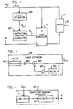
- Fig. 1 shows in simplified block diagram form a transmission network including an aspect of the invention. The embodiment of Fig. 1 is intended to couple via hybrid 101 a bidirectional transmission path or
facility 102 to a circuit arrangement including incoming unidirectional transmission path orfacility 103 and outgoing unidirectional transmission path orfacility 104. Such incoming and outgoing circuit arrangements are, are example, four-wire transmission facility or switching machine terminations. - Accordingly, incoming signals are supplied via
unidirectional transmission path 103 topower estimator 105, an X input ofecho canceler 106 andhybrid 101 and, hence, tobidirectional transmission path 102. Outgoing signals frombidirectional path 102 are supplied viahybrid 101 to the Y input ofecho canceler 106. An output signal from the E output ofecho canceler 106 is supplied to outgoingunidirectional transmission path 104.Power estimator 105 generates power estimate X(k) which is supplied to adaptationconstant calculator 107. Adaptationconstant calculator 107 generates a normalized gain value K which has a characteristic in relationship to power estimate X(k), in accordance with an aspect of the invention, so that normalized gain value K is controllably adjusted to have a prescribed value when the value of power estimate X(k) exceeds a predetermined threshold value. Normalized gain value K is supplied toecho canceler 106 where it is used to adjust the normalized update gain for all the taps therein. - It is noted that large values of power estimate X(k) only occur when the transmission network is in a so-called "singing" condition, i.e., oscillating, and, consequently, prior gain normalization arrangements would cause a low value of normalized gain value K to be generated which slows down the correction of the oscillating condition. We have determined that as X(k) becomes large in value, the singing condition can be avoided or its length of time minimized by either boosting the normalized gain value to be a value greater than that which would normally be generated for the power estimate values which exceed a prescribed threshold value or setting it at a fixed value. A specific normalized gain characteristic, not to be construed as limiting the scope of the invention, is shown in Fig. 5.
- Fig. 2 shows in simplified block diagram form details of an adaptive filter which is advantageously employed for
echo canceler 106. Echocanceler 106 is broadly similar to echo cancelers disclosed in US-A-3,499,999 and 3,500,000. Also see an article entitled "A Single-Chip VLSI Echo Canceler", by D. L. Duttweiler and Y. S. Chen, The Bell System Technical Journal, Vol. 59, No. 2, February 1980, pages 149-159, and an article entitled "Bell's Echo-Killer Chip", IEEE Spectrum, October 1080, pages 34-37. In thisembodiment echo canceler 106 also includes an arrangement for controllably adjusting the normalized update gain of each tap in the adaptive filter employed in the echo canceler. - Briefly,
canceler 106 includes an adjustable signal processor, i.e., adaptive filter having a closed loop error control system which is self- adapting in that it automatically tracks signal variation in an outgoing path. More specifically, canceler 106 employsecho estimator 201 including an adaptive transversal filter arrangement for synthesizing a linear approximation of the echo, i.e., an echo estimate. - To this end, far end incoming signal X(k) is usually supplied from a far end talking party over a first transmission path, e.g., path 103 (Fig. 1), to a first input, namely input X, of
echo canceler 106 and therein to an input ofecho estimator 201. Far end signal X(k) may be, for example, a digitially sampled speech signal, where k is an integer identifying the sampling interval. However, because of an impedance mismatch, for example, in hybrid 101 (Fig. 1), a portion of the hybrid input signal is reflected to the far end signal source as an echo. The echo is supplied from an output ofhybrid 101 to the Y input of canceler 109 and therein to a first input of combiningnetwork 202. A second input to combiningnetwork 202 is a signal estimate of the echo generated byecho estimator 201. The echo estimate is supplied vialead 203 from an output ofecho estimator 201 to the second input of combiningnetwork 202. Combiningnetwork 202 generates error signal E(k) corresponding to the algebraic difference between the echo estimate and the Y input to the echo canceler including the undesirable echo. Error signal E(k) is supplied via output E to path 104 (Fig. 1) and to adjustment networks 204-O through 204-(N-1) inestimator 201. -
Estimator 201 includes a so-called tapped delay line comprised of delay units 205-1 through 205-N for realizing desired delays at the taps corresponding to convenient Nyquist intervals. Therefore, delayed replicas X(k-1) through X(k-N) of incoming far end signal X(k) are generated at the corresponding taps. The signal at each tap position, namely X(k-1) through X(k-N) as well as X(k), is adjusted in response to error signal E(k). More particularly, signals X(k) through X(k-N) are individually weighted in response to E(k) via a corresponding one of adjustment networks 204-O through 204-N, respectively: Adjustment networks 204-0 through 204-N each includemultipliers feedback circuit 209.Feedback circuit 209 adjusts the tap weight to a desired value in a manner which will be apparent to those skilled in the art and explained in the above-noted references. In this adjustment, it is important to adjust the individual loop gains K(k) viacontrollable amplifier 210 to result in a stable system and, in accordance with the invention, to eliminate or minimize "singing", i.e., oscillation. This is realized by adjusting the loop gain K with the value normalized in accordance with the characteristic shown in Fig. 5 and generated by the adaptation constant calculator. The weighted replicas of X(k) from adjustment networks 204-0 through 204-(N-1) are summed via summingnetwork 211 to generate the echo estimate signal approximating the echo to be canceled. The echo estimate is supplied vialead 203 to the second input of combiningnetwork 202. In one embodiment, the number (N) of taps inecho canceler 106 is 24. - Fig. 3 shows in simplified block diagram form details of
power estimator 105 employed in the embodiments of Fig. 1 and Fig. 6.Power estimator 105 is essentially a low pass filter having a characteristic
rectifier 301 to generate |X(k)|. Then, )X(k)) is amplified by factor a inamplifier 302 and α|X(k)| is supplied to one input ofadder 303. An output fromadder 303 is X(k). X(k) is supplied viadelay unit 304 andamplifier 305 to a second input ofadder 303.Delay unit 304 delays X(k) by a sampling interval to yield X(k-1) andamplifier 305 amplifies X(k-1) to generate (1-a)X(k-1) which is supplied to the second input ofadder 303. - Fig. 4 depicts in simplified block diagram form details of adaptation
constant calculator 107 employed in the embodiment of Fig. 1. Accordingly, X(k) is supplied tounit 401 which generates LOG(X(k)). In turn,unit 402 generates K[LOG(X(k))] and yields K in accordance with the characteristic shown in Fig. 5. This is realizable by using a table look-up. That is to say, K[LOG(X(k))] is the address in a read only memory (ROM) for the value of K. Alternatively, the value of X(k) can be used directly to address a ROM to generate a corresponding value of K. - Fig. 5 shows a normalized gain characteristic which may be employed, in accordance with an aspect of the invention, to minimize "singing", i.e., oscillating, in the embodiments of Figs. 1 and 6. Heretofore, as X(k) or, in this example, LOG[X(k)] increased, the normalized gain K would continue to decrease. This resulted in problems because large values of X(k) typically occur only when the circuit is singing, i.e., oscillating, and the "low" value of the normalized gain K slows down the recovery from instability and oscillating. As shown in Fig. 5, the normalized gain K for "large" values of X(k) is boosted so that it remains, in this example, at a fixed predetermined value. It is again noted that the gain boost for large values of X(k) does not affect the normal voice frequency signals because their average power levels are not as large as those resulting during singing intervals. Typical values of normalized gain K for XMAX(k) in dBmo are as follows:

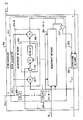
- Fig. 6 shows in simplified block diagram form details of an automatically adaptive bidirectional voice frequency repeater employing aspects of the invention. The repeater shown in Fig. 6 is intended to enhance voice frequency signals being transmitted on a 2-wire transmission path or facility.
- Accordingly, shown in Fig. 6 are
hybrid circuits 601 and 602 which are adapted for coupling signals to and from the repeater to bidirectional transmission paths A and B, respectively.Hybrids 601 and 602 may be any of the hybrid arrangements known in the art for coupling signals from a bidirectional 2-wire transmission path or facility to incoming and outgoing unidirectional transmission paths or facilities. In one example,hybrids 601 and 602 are of the electronic type. - An incoming signal output from hybrid 601 is supplied to an encoder input of
CODEC 603. In this example, the encoder ofCODEC 603 converts the analog input signal into an 8-bit µ-law PCM digital signal, in well-known fashion. The 8-bit u-law PCM digital signal fromCODEC 603 is supplied to a Y input ofecho canceler 604. Output E fromecho canceler 604 is supplied viaequalizer 605 andgain unit 606 to an X input ofecho canceler 607, to a decoder input ofCODEC 608 and topower estimator 609. The decoder ofCODEC 608 converts the 8-bit li-law PCM output fromecho canceler 604 into an analog output signal, in well-known fashion. The analog output fromCODEC 608 is supplied tohybrid 602 and, in turn, to bidirectional 2-wire facility B. - An analog signal from bidirectional 2-wire facility B is supplied via
hybrid 602 to an encoder input ofCODEC 608. In turn,CODEC 608 converts the analog input signal, in this example, into a digital p-law PCM signal which is supplied to the Y input ofecho canceler 607. Output E fromecho canceler 607 is supplied viaequalizer 610 andgain unit 611 to the X input ofecho canceler 604, to a decoder input ofCODEC 603 and topower estimator 612.CODEC 603 converts the 8-bit u-law output E fromecho canceler 607 into an analog signal, in well-known fashion. The analog signal fromCODEC 603 is supplied via hybrid 601 to bidirectional 2-wire facility A. -
Echo canceler 604 is employed to cancel the echo signal or reflected signal resulting in the signal transmission from bidirectional 2-wire facility A because of the signal incoming to the repeater from bidirectional 2-wire facility B. Similarly, echocanceler 607 is employed to cancel the echo or reflected signal resulting in the signal transmission from bidirectional 2-wire facility B because of the signal incoming to the repeater from bidirectional facility A. Details of an echo canceler which may be employed forcancelers - In this example, equalizers 119 and 124 each include an eighth order finite impulse response filter mf a type known in the art.
-
Power estimators power estimator 105, details of which are shown in Fig. 3 and have been described above. Accordingly,power estimator 609 generates power estimate XA(k) of XA(k), in accordance with equation (1), which is supplied to adaptationconstant calculator 613. Similarly,power estimator 612 generates power estimate XB(k) of Xε(k), in accordance with equation (1), which is also supplied to adaptationconstant calculator 613. - Adaptation
constant calculator 613 generates normalized gain value K in a manner described below which is supplied to both the echo cancelers 604 and 607 to set the update gain for all the taps in each of the transversal filters used therein. In accordance with an aspect of the invention, adaptationconstant calculator 613 selects between power estimate XB(k) and XA(k) in accordance with a prescribed criterion for generating normalized gain value K which is then used to adjust the update gain in each of echo cancelers 604 and 607. Consequently, each of echo cancelers 604 and 607 is allowed to adapt to a desired impulse response characteristic even when there is "talking" in both directions of transmission. Heretofore, talking in each direction of transmission would have caused both echo cancelers to be inhibited from being updated. - Use of the same update gain value K for both directions of transmission also helps when singing, i.e, oscillating, is occurring to stablize the repeater. That is, if one of the power estimates XA(k) or XB(k) is large relative to normally expected voice band signals, an unstable system is indicated and the update gain is controllably adjusted, as described above in relationship to the embodiment of Fig. 1, for both echo
cancelers - Fig. 7 shows in block diagram form details of adaptation
constant calculator 613 used in the embodiment of Fig. 6. Accordingly, power estimate XA(k) is supplied to one input ofcomparator 701 and to input A ofdigital selector 702 while power estimateX B(k) is supplied to a second input ofcomparator 701 and to input B ofselector 702.Comparator 701 generates an output representative of a logical 1 or true signal whenX A(k)>X B(k). This output fromcomparator 701 is supplied to the select input ofdigital selector 702.Selector 702 is operative to normally supply XB(k) to its output except when XA(k) is selected in response to the true signal fromcomparator 701. Simply stated, the output fromselector 702 is the maximum of XA(k) and XB(k), i.e., XMAX(k). - The XMAX(k) signal is supplied to log unit 703 which generates its logarithm, namely, LOG[
X MAX(k)]. The LOG[XMAx(k)] value is used as an address to access a look-up table to generate normalized update gain value K, in this example, in accordance with the characteristic shown in Fig. 5. The look-up table is stored, for example, in a read only memory (ROM). - Although the embodiments of the present invention have been described in simplified block diagram form, preferred embodiments are realized by appropriately programming a digital signal processor to obtain the equalizer, gain unit, power estimator, adaptation constant calculator and echo canceler functions. One such digital signal processor (DSP) unit is manufactured by American Telephone & Telegraph Co. and is described in several articles in The Bell System Technical Journal, Vol. 60, No. 7, Part 2, dated September 1981. A prior known repeater employing a digital signal processor is broadly described in an article entitled, "Digital Signal Solves Hybrid Balance Puzzle", Telephone Engineer & Management, August 1, 1983, pages 39―46.
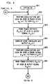
- Accordingly, the equalizer, gain unit, power estimator, adaptation constant calculator and echo canceler functions of the bidirectional repeater of Fig. 6 are realized by programming a DSP unit. Operation of the repeater, in accordance with aspects of the invention, is described in conjunction with the digital program flow chart of Figs. 8 and 9. Figs. 8 and 9 when connected AA-AA and BB-BB form a flow chart of a program routine for realizing the above-noted repeater functions. Thus, the DSP is initialized in well-known fashion via 801.
Operational block 802 performs the equalization and gain functions on error signal es(k) fromecho canceler 607 to form the A side signal XA(k). Then,operational block 803 forms the power estimate XA(k) of XA(k).Operational block 804 causes the generation ofecho canceler 604 error signal eA(k). This is achieved by employing a known echo canceler algorithm, for example, the one disclosed in the article entitled "A Single-Chip VLSI Echo Canceler" cited above.Operational block 805 causes the equalization and gain functions to be performed on the side A error signal eA(k) to form side B output signal XB(k). Then,operational block 806 causes power estimate Xs(k) to be formed of side B output signal XB(k).Operational block 807 causes echocanceler 607 error signal output eB(k) to be computed. This computation is realized in the same fashion as for eA(b) inoperational block 804.Operational block 810 causesX MAX(k)=MAX of XA(k), Xµ(b) to be found. Then,operational block 809 converts XMAx(b) to logarithmic form.Operational block 810 generates an address for the adaptation constant, i.e., normalized gain value K using LOG(XM"x(k)).Operational block 811 causes echocanceler 604 to be updated using adaptation constant K. Similarly,operational block 812 causes echocanceler 607 to be updated also using adaptation constant K.
Claims (9)
Applications Claiming Priority (2)
| Application Number | Priority Date | Filing Date | Title |
|---|---|---|---|
| US06/654,410 US4591669A (en) | 1984-09-26 | 1984-09-26 | Adaptive filter update gain normalization |
| US654410 | 1984-09-26 |
Publications (2)
| Publication Number | Publication Date |
|---|---|
| EP0176312A1 EP0176312A1 (en) | 1986-04-02 |
| EP0176312B1 true EP0176312B1 (en) | 1989-05-24 |
Family
ID=24624729
Family Applications (1)
| Application Number | Title | Priority Date | Filing Date |
|---|---|---|---|
| EP85306609A Expired EP0176312B1 (en) | 1984-09-26 | 1985-09-17 | Adaptive filter update gain normalization |
Country Status (5)
| Country | Link |
|---|---|
| US (1) | US4591669A (en) |
| EP (1) | EP0176312B1 (en) |
| JP (1) | JPH0671220B2 (en) |
| CA (1) | CA1220823A (en) |
| DE (1) | DE3570561D1 (en) |
Families Citing this family (35)
| Publication number | Priority date | Publication date | Assignee | Title |
|---|---|---|---|---|
| EP0167677B1 (en) * | 1984-07-13 | 1989-03-08 | BELL TELEPHONE MANUFACTURING COMPANY Naamloze Vennootschap | Signal processing arrangement |
| JPS62104324A (en) * | 1985-10-31 | 1987-05-14 | Toshiba Corp | Adaptive automatic equalizer |
| US4697261A (en) * | 1986-09-05 | 1987-09-29 | M/A-Com Government Systems, Inc. | Linear predictive echo canceller integrated with RELP vocoder |
| US4845746A (en) * | 1987-06-23 | 1989-07-04 | Rockwell International Corporation | Echo canceller with relative feedback control |
| FR2618277B1 (en) * | 1987-07-16 | 1989-12-15 | Centre Nat Rech Scient | ADAPTIVE PREDICATOR. |
| JPH02280422A (en) * | 1989-04-20 | 1990-11-16 | Nec Corp | Training method for echo canceller for voice conference equipment |
| NL8901247A (en) * | 1989-05-19 | 1990-12-17 | Philips Nv | ADAPTIVE TIME DISCREET TRANSVERSAL FILTER. |
| CA2026558C (en) * | 1989-09-28 | 1994-07-05 | Kensaku Fujii | Adaptive digital filter including low-pass filter |
| FR2671221B1 (en) * | 1990-12-27 | 1995-03-31 | Alcatel Radiotelephone | DEVICE FOR CANCELING ACOUSTIC NOISE. |
| DE69222787T2 (en) * | 1991-02-20 | 1998-02-19 | Nec Corp | Method and device for checking the coefficients of an adaptive filter |
| JP2842026B2 (en) * | 1991-02-20 | 1998-12-24 | 日本電気株式会社 | Adaptive filter coefficient control method and apparatus |
| EP0515761A1 (en) * | 1991-05-31 | 1992-12-02 | International Business Machines Corporation | Adaptive equalization system and method for equalizing a signal into a DCE |
| DE69207509T2 (en) * | 1991-08-20 | 1996-08-22 | Philips Electronics Nv | Telecommunication system with a line for digital traffic with an arrangement for branching the digital duplex traffic, and arrangement for use in the telecommunication system |
| US5268927A (en) * | 1992-10-06 | 1993-12-07 | Mayflower Communications Company, Inc. | Digital adaptive transversal filter for spread spectrum receivers |
| US5412686A (en) * | 1993-09-17 | 1995-05-02 | Motorola Inc. | Method and apparatus for power estimation in a communication system |
| FI935834A (en) * | 1993-12-23 | 1995-06-24 | Nokia Telecommunications Oy | A method for adapting to an echo point in an echo canceller |
| JP2947093B2 (en) * | 1994-11-02 | 1999-09-13 | 日本電気株式会社 | Method and apparatus for system identification with adaptive filters |
| JP3381112B2 (en) * | 1995-03-09 | 2003-02-24 | ソニー株式会社 | Echo canceler |
| US5596600A (en) * | 1995-04-06 | 1997-01-21 | Mayflower Communications Company, Inc. | Standalone canceller of narrow band interference for spread spectrum receivers |
| US5734715A (en) * | 1995-09-13 | 1998-03-31 | France Telecom | Process and device for adaptive identification and adaptive echo canceller relating thereto |
| FR2738695B1 (en) * | 1995-09-13 | 1997-11-14 | France Telecom | ADAPTIVE IDENTIFICATION METHOD AND DEVICE AND ADAPTIVE ECHO CANCELER INCLUDING SUCH A DEVICE |
| SE505152C2 (en) * | 1995-10-11 | 1997-07-07 | Ericsson Telefon Ab L M | Adaptive echo extinguishing procedure |
| US5668865A (en) * | 1996-02-26 | 1997-09-16 | Lucent Technologies Inc. | Echo canceler E-side speech detector |
| JP2924762B2 (en) * | 1996-02-28 | 1999-07-26 | 日本電気株式会社 | Adaptive filter and adaptation method thereof |
| EP0831478B1 (en) * | 1996-09-24 | 2003-11-19 | Hewlett-Packard Company, A Delaware Corporation | Data processing apparatus and methods |
| US6185299B1 (en) * | 1997-10-31 | 2001-02-06 | International Business Machines Corporation | Adaptive echo cancellation device in a voice communication system |
| US6570985B1 (en) | 1998-01-09 | 2003-05-27 | Ericsson Inc. | Echo canceler adaptive filter optimization |
| US6249147B1 (en) | 1999-03-09 | 2001-06-19 | Fujitsu, Ltd. | Method and apparatus for high speed on-chip signal propagation |
| US7512149B2 (en) * | 2003-04-23 | 2009-03-31 | At & T Intellectual Property Ii, L.P. | Bit and power allocation scheme for full-duplex transmission with echo cancellation in multicarrier-based modems |
| US6813352B1 (en) | 1999-09-10 | 2004-11-02 | Lucent Technologies Inc. | Quadrature filter augmentation of echo canceler basis functions |
| DE10030123A1 (en) * | 2000-06-20 | 2002-01-03 | Infineon Technologies Ag | Circuit arrangement for analog echo cancellation |
| GB2372653A (en) * | 2000-09-29 | 2002-08-28 | Univ Bristol | Adaptive filters |
| US7035397B2 (en) * | 2001-09-14 | 2006-04-25 | Agere Systems Inc. | System and method for updating filter coefficients and echo canceller including same |
| US7151803B1 (en) | 2002-04-01 | 2006-12-19 | At&T Corp. | Multiuser allocation method for maximizing transmission capacity |
| EP1695453A1 (en) * | 2003-12-10 | 2006-08-30 | Koninklijke Philips Electronics N.V. | Echo canceller having a series arrangement of adaptive filters with individual update control strategy |
Citations (1)
| Publication number | Priority date | Publication date | Assignee | Title |
|---|---|---|---|---|
| US3922505A (en) * | 1972-08-10 | 1975-11-25 | Siemens Ag | Echo canceller |
Family Cites Families (5)
| Publication number | Priority date | Publication date | Assignee | Title |
|---|---|---|---|---|
| JPS579258B1 (en) * | 1971-05-15 | 1982-02-20 | ||
| US4129753A (en) * | 1977-12-09 | 1978-12-12 | Bell Telephone Laboratories, Incorporated | Echo canceller using feedback to improve speech detector performance |
| US4468641A (en) * | 1982-06-28 | 1984-08-28 | At&T Bell Laboratories | Adaptive filter update normalization |
| US4468640A (en) * | 1982-06-28 | 1984-08-28 | At&T Bell Laboratories | Adaptive filter update normalization |
| US4467441A (en) * | 1982-10-08 | 1984-08-21 | At&T Bell Laboratories | Adaptive filter including controlled tap coefficient leakage |
-
1984
- 1984-09-26 US US06/654,410 patent/US4591669A/en not_active Expired - Lifetime
-
1985
- 1985-08-30 CA CA000489848A patent/CA1220823A/en not_active Expired
- 1985-09-17 DE DE8585306609T patent/DE3570561D1/en not_active Expired
- 1985-09-17 EP EP85306609A patent/EP0176312B1/en not_active Expired
- 1985-09-26 JP JP60211205A patent/JPH0671220B2/en not_active Expired - Fee Related
Patent Citations (1)
| Publication number | Priority date | Publication date | Assignee | Title |
|---|---|---|---|---|
| US3922505A (en) * | 1972-08-10 | 1975-11-25 | Siemens Ag | Echo canceller |
Non-Patent Citations (1)
| Title |
|---|
| IEEE Transactions on Communications, Vol. COM-26, No. 5, May 1978, pp. 647-653 * |
Also Published As
| Publication number | Publication date |
|---|---|
| DE3570561D1 (en) | 1989-06-29 |
| EP0176312A1 (en) | 1986-04-02 |
| CA1220823A (en) | 1987-04-21 |
| JPS6184927A (en) | 1986-04-30 |
| JPH0671220B2 (en) | 1994-09-07 |
| US4591669A (en) | 1986-05-27 |
Similar Documents
| Publication | Publication Date | Title |
|---|---|---|
| EP0176312B1 (en) | Adaptive filter update gain normalization | |
| US4998241A (en) | Echo canceller | |
| US4636586A (en) | Speakerphone with adaptive cancellation of room echoes | |
| US5313498A (en) | Method and arrangement of echo elimination in digital telecommunications system | |
| US4922530A (en) | Adaptive filter with coefficient averaging and method | |
| US4845746A (en) | Echo canceller with relative feedback control | |
| JP2853455B2 (en) | Echo canceller | |
| US4491701A (en) | Adaptive filter including a far end energy discriminator | |
| GB2202717A (en) | Double-talk detection in echo cancellers | |
| JP3877882B2 (en) | Adaptive filter | |
| EP0114855B1 (en) | Adaptive filter update normalization | |
| US4467441A (en) | Adaptive filter including controlled tap coefficient leakage | |
| US4574166A (en) | Tandem adaptive filter arrangement | |
| US6687373B1 (en) | Heusristics for optimum beta factor and filter order determination in echo canceler systems | |
| US4628157A (en) | Bidirectional adaptive voice frequency repeater | |
| US4468640A (en) | Adaptive filter update normalization | |
| US4584441A (en) | Bidirectional adaptive voice frequency repeater | |
| US4405840A (en) | Echo canceler far end energy discriminator | |
| WO1982003144A1 (en) | Energy band discriminator | |
| EP0855110B1 (en) | An adaptive echo cancellation method | |
| US20030076844A1 (en) | Method and system for filtering a signal and providing echo cancellation using an adaptive length filter | |
| EP0117626A2 (en) | Improvements in or relating to adaptive filter arrangements | |
| JPH0946277A (en) | Echo canceller | |
| JPH0380370B2 (en) |
Legal Events
| Date | Code | Title | Description |
|---|---|---|---|
| PUAI | Public reference made under article 153(3) epc to a published international application that has entered the european phase |
Free format text: ORIGINAL CODE: 0009012 |
|
| AK | Designated contracting states |
Kind code of ref document: A1 Designated state(s): DE FR GB IT NL |
|
| 17P | Request for examination filed |
Effective date: 19860904 |
|
| 17Q | First examination report despatched |
Effective date: 19880714 |
|
| GRAA | (expected) grant |
Free format text: ORIGINAL CODE: 0009210 |
|
| AK | Designated contracting states |
Kind code of ref document: B1 Designated state(s): DE FR GB IT NL |
|
| ITF | It: translation for a ep patent filed |
Owner name: MODIANO & ASSOCIATI S.R.L. |
|
| REF | Corresponds to: |
Ref document number: 3570561 Country of ref document: DE Date of ref document: 19890629 |
|
| ET | Fr: translation filed | ||
| PLBE | No opposition filed within time limit |
Free format text: ORIGINAL CODE: 0009261 |
|
| STAA | Information on the status of an ep patent application or granted ep patent |
Free format text: STATUS: NO OPPOSITION FILED WITHIN TIME LIMIT |
|
| 26N | No opposition filed | ||
| ITTA | It: last paid annual fee | ||
| REG | Reference to a national code |
Ref country code: GB Ref legal event code: IF02 |
|
| PGFP | Annual fee paid to national office [announced via postgrant information from national office to epo] |
Ref country code: FR Payment date: 20020822 Year of fee payment: 18 |
|
| PGFP | Annual fee paid to national office [announced via postgrant information from national office to epo] |
Ref country code: GB Payment date: 20020827 Year of fee payment: 18 |
|
| PGFP | Annual fee paid to national office [announced via postgrant information from national office to epo] |
Ref country code: NL Payment date: 20020906 Year of fee payment: 18 |
|
| PGFP | Annual fee paid to national office [announced via postgrant information from national office to epo] |
Ref country code: DE Payment date: 20020916 Year of fee payment: 18 |
|
| PG25 | Lapsed in a contracting state [announced via postgrant information from national office to epo] |
Ref country code: GB Free format text: LAPSE BECAUSE OF NON-PAYMENT OF DUE FEES Effective date: 20030917 |
|
| PG25 | Lapsed in a contracting state [announced via postgrant information from national office to epo] |
Ref country code: NL Free format text: LAPSE BECAUSE OF NON-PAYMENT OF DUE FEES Effective date: 20040401 Ref country code: DE Free format text: LAPSE BECAUSE OF NON-PAYMENT OF DUE FEES Effective date: 20040401 |
|
| GBPC | Gb: european patent ceased through non-payment of renewal fee |
Effective date: 20030917 |
|
| PG25 | Lapsed in a contracting state [announced via postgrant information from national office to epo] |
Ref country code: FR Free format text: LAPSE BECAUSE OF NON-PAYMENT OF DUE FEES Effective date: 20040528 |
|
| NLV4 | Nl: lapsed or anulled due to non-payment of the annual fee |
Effective date: 20040401 |
|
| REG | Reference to a national code |
Ref country code: FR Ref legal event code: ST |