EP0176687A2 - Sealing device for throttle valves - Google Patents
Sealing device for throttle valves Download PDFInfo
- Publication number
- EP0176687A2 EP0176687A2 EP85109274A EP85109274A EP0176687A2 EP 0176687 A2 EP0176687 A2 EP 0176687A2 EP 85109274 A EP85109274 A EP 85109274A EP 85109274 A EP85109274 A EP 85109274A EP 0176687 A2 EP0176687 A2 EP 0176687A2
- Authority
- EP
- European Patent Office
- Prior art keywords
- sealing
- ring
- body part
- slot
- flanges
- Prior art date
- Legal status (The legal status is an assumption and is not a legal conclusion. Google has not performed a legal analysis and makes no representation as to the accuracy of the status listed.)
- Granted
Links
Images
Classifications
-
- F—MECHANICAL ENGINEERING; LIGHTING; HEATING; WEAPONS; BLASTING
- F16—ENGINEERING ELEMENTS AND UNITS; GENERAL MEASURES FOR PRODUCING AND MAINTAINING EFFECTIVE FUNCTIONING OF MACHINES OR INSTALLATIONS; THERMAL INSULATION IN GENERAL
- F16K—VALVES; TAPS; COCKS; ACTUATING-FLOATS; DEVICES FOR VENTING OR AERATING
- F16K1/00—Lift valves or globe valves, i.e. cut-off apparatus with closure members having at least a component of their opening and closing motion perpendicular to the closing faces
- F16K1/16—Lift valves or globe valves, i.e. cut-off apparatus with closure members having at least a component of their opening and closing motion perpendicular to the closing faces with pivoted closure-members
- F16K1/18—Lift valves or globe valves, i.e. cut-off apparatus with closure members having at least a component of their opening and closing motion perpendicular to the closing faces with pivoted closure-members with pivoted discs or flaps
- F16K1/22—Lift valves or globe valves, i.e. cut-off apparatus with closure members having at least a component of their opening and closing motion perpendicular to the closing faces with pivoted closure-members with pivoted discs or flaps with axis of rotation crossing the valve member, e.g. butterfly valves
- F16K1/226—Shaping or arrangements of the sealing
- F16K1/2263—Shaping or arrangements of the sealing the sealing being arranged on the valve seat
Definitions
- the invention relates to a sealing device for such throttle valves as comprise a valve housing with a valve seat and a pivotally movable throttle member which may be pressed against the valve seat to bring about a sealing contact between two interacting sealing surfaces, one on the throttle member and the other in the valve housing and a sealing ring to be mounted in a slot in the valve.
- a sealing device of the type referred to in the preamble is known for instance from US-A-428426 4 .
- This known device comprises a homogeneous sealing ring intended to be mounted in a slot in the valve housing.
- the valve ring cross-section is an elongated flat body.
- the ring normally consists of metal and is considerably rigid with respect to deformation in the radial direction.
- the ring may, however, be bent aside by the throttle, when the throttle is pressed against the sealing ring.
- the inner, bluntly rounded edge of the ring constitutes the second sealing surface referred to above.
- a pair of spring washers are pressed against the two flat sides of the sealing nng, and between these two washers is formed the slot in which the sealing ring is mounted.
- the spring washers are in turn arranged between the valve housing and a mounting ring, gaskets being placed between the latter parts and the spring washers.
- the object of the invention is to provide an improved sealing device for throttle valves of the type referred to in the preamble.
- an object is to eliminate the disadvantage listed above of prior art sealing devices for throttle valves.
- the sealing ring having a homogeneous, radially ablong body part of considerable rigidity and resistance to radial deformation, by the homogeneous body part having at its head end a sealing surface, constituting one of the two sealing surfaces mentioned in the preamble, and by two essentially radially directed legs extending from the "hip" portion of the homogeneous body, said legs forming 1 , 1 nge-like extensions of the sealing ring, said extensions being intended to be pressed in the axial direction against the walls of the slot.
- the valve comprises a valve housing 1 with a main part and a cover ring 3; a pivotally mounted throttle 4; and a sealing ring 5 in an annular slot 6 in the valve housing between the main part 2 and the cover ring 3.
- the throttle 4 has a sealing surface 7, which according to this embodiment is of the same configuration as in US-A-4284264.
- the sealing device according to the invention is not limited, however, to be used with this throttle configuration.
- the sealing ring 5 normally consists of stainless, acid- proof steel; an alternative is a very stiff plastic material. It is also conceivable that the ring 5 consists of a composite material or is composed of several materials.
- the ring 5 has a section which has a "creature"-resembling configuration with an elongated body part 8. The two sides 9, 10 of the body part 8 are completely flat and parallel. At that end 7 of the ring, which is directed toward the throttle member, the body part 8 is transfigurated directly into a "head" part 11 with a bluntly rounded surface 12, which constitutes the first sealing surface of the valve, against which the sealing surface 7 of the throttle 4 may be pressed.
- a pair of annular flanges 14, 15 extend radially, symmetrically outwards.
- the flanges 14 and 15 form the legs of the creature-resembling figure.
- the feet/ledges 16, 17 are pressed by spring action of the legs/flanges 14, 15 against the walls 18 and 19, respectively, of the slot 6.
- the configuration of the ring 5 ensures the desired combination of radial rigidity, axial flexibility, and sealing ability against the two walls 18, 19 of the slot 6.
- the ring 5 by itself is stiff enough, which means that the two legs/flanges 14, 15 need not “brace their feet" 16, 17 against the bottom 20 of the slot 6.
- the slot 6 is so deep that the ring 5 may be displaced radially, i.e. the diameter of the slot 6 is greater than the outer diameter of the ring 5.
- the position of the ring 5 is thus adaptable to the throttle 4 when the valve is first closed. During this adaptation, the feet/ledges 1 6, 17 will slide against the parallel radial walls 18, 19 of the slot 6 without losing their sealing contact with them.
Abstract
Description
- The invention relates to a sealing device for such throttle valves as comprise a valve housing with a valve seat and a pivotally movable throttle member which may be pressed against the valve seat to bring about a sealing contact between two interacting sealing surfaces, one on the throttle member and the other in the valve housing and a sealing ring to be mounted in a slot in the valve.
- A sealing device of the type referred to in the preamble is known for instance from US-A-4284264. This known device comprises a homogeneous sealing ring intended to be mounted in a slot in the valve housing. The valve ring cross-section is an elongated flat body. The ring normally consists of metal and is considerably rigid with respect to deformation in the radial direction. The ring may, however, be bent aside by the throttle, when the throttle is pressed against the sealing ring. The inner, bluntly rounded edge of the ring constitutes the second sealing surface referred to above. A pair of spring washers are pressed against the two flat sides of the sealing nng, and between these two washers is formed the slot in which the sealing ring is mounted. The spring washers are in turn arranged between the valve housing and a mounting ring, gaskets being placed between the latter parts and the spring washers. Although this known device has several positive qualities compared to prior art and has signified a substantial improvement within this particular field, the two spring washers and the gaskets do constitute a complication.
- From for instance US-A-3080145 and US-A-4058290 the use of sealing washers with a U-shaped section is known for throttle valves with metallic sealing. In comparison with US-A-4284264 these have the advantage of being uncomplicated and not requiring separate gaskets. On the other hand, they have a low rigidity and resistance to radial deformation, which is unsatisfactory at least for some applications.
- The object of the invention is to provide an improved sealing device for throttle valves of the type referred to in the preamble. In particular, an object is to eliminate the disadvantage listed above of prior art sealing devices for throttle valves.
- These and other objects may be accomplished by the sealing ring having a homogeneous, radially ablong body part of considerable rigidity and resistance to radial deformation, by the homogeneous body part having at its head end a sealing surface, constituting one of the two sealing surfaces mentioned in the preamble, and by two essentially radially directed legs extending from the "hip" portion of the homogeneous body, said legs forming 1,1nge-like extensions of the sealing ring, said extensions being intended to be pressed in the axial direction against the walls of the slot.
- Further advantages and characteristics of the invention will become apparent from the appended claims and the following description of a preferred embodiment.
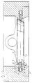
- In the following description reference will be made to the drawing figure, which shows an axial section of a throttle valve with a sealing device according to the invention. The valve comprises a valve housing 1 with a main part and a cover ring 3; a pivotally mounted throttle 4; and a
sealing ring 5 in an annular slot 6 in the valve housing between themain part 2 and the cover ring 3. The throttle 4 has a sealing surface 7, which according to this embodiment is of the same configuration as in US-A-4284264. The sealing device according to the invention is not limited, however, to be used with this throttle configuration. - The sealing
ring 5 normally consists of stainless, acid- proof steel; an alternative is a very stiff plastic material. It is also conceivable that thering 5 consists of a composite material or is composed of several materials. Thering 5 has a section which has a "creature"-resembling configuration with an elongated body part 8. The twosides 9, 10 of the body part 8 are completely flat and parallel. At that end 7 of the ring, which is directed toward the throttle member, the body part 8 is transfigurated directly into a "head" part 11 with a bluntly rounded surface 12, which constitutes the first sealing surface of the valve, against which the sealing surface 7 of the throttle 4 may be pressed. - From the "hip" 13 of the body part 8, i.e. from the peripheral part of the homogeneous part of the
ring 5, a pair of annular flanges 14, 15 extend radially, symmetrically outwards. In the section illustrated, the flanges 14 and 15 form the legs of the creature-resembling figure. On the legs 14. 15 there extend a pair offeet 16, 17, each being an outwardly pointing ledge on the respective flanges 14, 15. The feet/ledges 16, 17 are pressed by spring action of the legs/flanges 14, 15 against the walls 18 and 19, respectively, of the slot 6. The configuration of thering 5 ensures the desired combination of radial rigidity, axial flexibility, and sealing ability against the two walls 18, 19 of the slot 6. Thering 5 by itself is stiff enough, which means that the two legs/flanges 14, 15 need not "brace their feet" 16, 17 against thebottom 20 of the slot 6. On the contrary, the slot 6 is so deep that thering 5 may be displaced radially, i.e. the diameter of the slot 6 is greater than the outer diameter of thering 5. The position of thering 5 is thus adaptable to the throttle 4 when the valve is first closed. During this adaptation, the feet/ledges 16, 17 will slide against the parallel radial walls 18, 19 of the slot 6 without losing their sealing contact with them.
Claims (5)
Priority Applications (1)
| Application Number | Priority Date | Filing Date | Title |
|---|---|---|---|
| AT85109274T ATE57426T1 (en) | 1984-09-27 | 1985-07-24 | SEALING DEVICE FOR THROTTLE VALVES. |
Applications Claiming Priority (2)
| Application Number | Priority Date | Filing Date | Title |
|---|---|---|---|
| SE8404833A SE445382B (en) | 1984-09-27 | 1984-09-27 | GAS VALVE SEALING DEVICE |
| SE8404833 | 1984-09-27 |
Publications (3)
| Publication Number | Publication Date |
|---|---|
| EP0176687A2 true EP0176687A2 (en) | 1986-04-09 |
| EP0176687A3 EP0176687A3 (en) | 1987-06-24 |
| EP0176687B1 EP0176687B1 (en) | 1990-10-10 |
Family
ID=20357147
Family Applications (1)
| Application Number | Title | Priority Date | Filing Date |
|---|---|---|---|
| EP85109274A Expired - Lifetime EP0176687B1 (en) | 1984-09-27 | 1985-07-24 | Sealing device for throttle valves |
Country Status (12)
| Country | Link |
|---|---|
| US (1) | US4634097A (en) |
| EP (1) | EP0176687B1 (en) |
| JP (1) | JP2528816B2 (en) |
| AT (1) | ATE57426T1 (en) |
| AU (1) | AU574491B2 (en) |
| BR (1) | BR8504281A (en) |
| CA (1) | CA1276925C (en) |
| DE (1) | DE3580087D1 (en) |
| FI (1) | FI82128C (en) |
| NO (1) | NO159617C (en) |
| SE (1) | SE445382B (en) |
| ZA (1) | ZA856570B (en) |
Cited By (3)
| Publication number | Priority date | Publication date | Assignee | Title |
|---|---|---|---|---|
| FR2606484A1 (en) * | 1986-11-12 | 1988-05-13 | Coyard Expl Ets E R | Butterfly valve |
| DE3744548A1 (en) * | 1987-01-02 | 1988-07-14 | Somas Ventiler | THROTTLE VALVE |
| DE102014222517A1 (en) * | 2014-11-04 | 2016-05-04 | Continental Automotive Gmbh | Valve device for a motor vehicle |
Families Citing this family (11)
| Publication number | Priority date | Publication date | Assignee | Title |
|---|---|---|---|---|
| FR2752033B1 (en) * | 1996-07-31 | 1998-09-11 | Ksb Sa | RIGID SEALING TAP |
| EP0822358B1 (en) * | 1996-07-31 | 2003-04-09 | Ksb S.A.S | Long life centric butterfly valve |
| US6328054B1 (en) * | 2000-07-07 | 2001-12-11 | Parker-Hannifin Corporation-Veriflo Division | Balanced fluid pressure regulator |
| DE10060004B4 (en) * | 2000-12-02 | 2005-08-25 | Warex Valve Gmbh | Shut-off device with a pivoting rotary flap and an entropy-elastic ring seal held on a support ring |
| US6981435B2 (en) * | 2003-05-08 | 2006-01-03 | Chih-Ching Hsien | Ratchet wrench having a sealing structure |
| DE102006045420A1 (en) * | 2006-09-26 | 2008-04-10 | Pierburg Gmbh | Throttle valve device for an internal combustion engine |
| FR2922984B1 (en) * | 2007-10-31 | 2013-09-27 | Saint Gobain Performance Plast | VALVE HAVING RIGID SEAL |
| US8348236B2 (en) * | 2007-10-31 | 2013-01-08 | Saint-Gobain Performance Plastics Corporation | Butterfly valve with a rigid seal |
| FR2922988B1 (en) | 2007-10-31 | 2012-10-12 | Saint Gobain Performance Plast | PIPE ASSEMBLIES |
| FR3067783B1 (en) * | 2017-06-20 | 2020-09-04 | Ksb Sas | CENTER BUTTERFLY VALVE |
| CN114791064A (en) * | 2021-01-26 | 2022-07-26 | 中国航发商用航空发动机有限责任公司 | Throttling assembly |
Citations (7)
| Publication number | Priority date | Publication date | Assignee | Title |
|---|---|---|---|---|
| US3080145A (en) * | 1957-10-24 | 1963-03-05 | David F Wiseman & Sons Ltd | Butterfly valves |
| DE1247104B (en) * | 1960-07-18 | 1967-08-10 | Marvin Henry Grove | Sealing ring |
| DE1802075B2 (en) * | 1967-11-07 | 1972-11-09 | Ateliers Des Charmilles S.A., Genf (Schweiz) | Throttle valve with uninterrupted seat seal |
| US4058290A (en) * | 1975-04-15 | 1977-11-15 | Neles Oy | Gate valve |
| AU506099B2 (en) * | 1976-02-25 | 1979-12-13 | Macawber Engineering | Rotary valve for abrasive materials |
| US4284264A (en) * | 1980-01-17 | 1981-08-18 | Aktiebolaget Somas Ventiler | Butterfly valves |
| DE3151787A1 (en) * | 1980-12-31 | 1982-07-15 | Masoneilan International, Inc., 02062 Norwood, Mass. | THROTTLE VALVE |
Family Cites Families (5)
| Publication number | Priority date | Publication date | Assignee | Title |
|---|---|---|---|---|
| US3029063A (en) * | 1958-08-29 | 1962-04-10 | Alfred M Moen | Butterfly valve |
| US4294283A (en) * | 1977-11-25 | 1981-10-13 | Scharres Harry J | Wedge sealed damper |
| US4254937A (en) * | 1978-11-17 | 1981-03-10 | Aktiebolaget Somas Ventiler | Butterfly valve |
| NO152308C (en) * | 1978-11-17 | 1985-09-04 | Somas Ventiler | Butterfly Valves |
| US4372530A (en) * | 1981-06-05 | 1983-02-08 | Quartrol Corporation | Valve and seal |
-
1984
- 1984-09-27 SE SE8404833A patent/SE445382B/en not_active IP Right Cessation
-
1985
- 1985-07-24 DE DE8585109274T patent/DE3580087D1/en not_active Expired - Lifetime
- 1985-07-24 AT AT85109274T patent/ATE57426T1/en not_active IP Right Cessation
- 1985-07-24 EP EP85109274A patent/EP0176687B1/en not_active Expired - Lifetime
- 1985-07-29 US US06/759,852 patent/US4634097A/en not_active Expired - Lifetime
- 1985-07-31 FI FI852962A patent/FI82128C/en not_active IP Right Cessation
- 1985-08-06 AU AU45808/85A patent/AU574491B2/en not_active Expired
- 1985-08-08 CA CA000488303A patent/CA1276925C/en not_active Expired - Lifetime
- 1985-08-14 NO NO853197A patent/NO159617C/en not_active IP Right Cessation
- 1985-08-28 ZA ZA856570A patent/ZA856570B/en unknown
- 1985-08-28 JP JP60187553A patent/JP2528816B2/en not_active Expired - Lifetime
- 1985-09-04 BR BR8504281A patent/BR8504281A/en not_active IP Right Cessation
Patent Citations (7)
| Publication number | Priority date | Publication date | Assignee | Title |
|---|---|---|---|---|
| US3080145A (en) * | 1957-10-24 | 1963-03-05 | David F Wiseman & Sons Ltd | Butterfly valves |
| DE1247104B (en) * | 1960-07-18 | 1967-08-10 | Marvin Henry Grove | Sealing ring |
| DE1802075B2 (en) * | 1967-11-07 | 1972-11-09 | Ateliers Des Charmilles S.A., Genf (Schweiz) | Throttle valve with uninterrupted seat seal |
| US4058290A (en) * | 1975-04-15 | 1977-11-15 | Neles Oy | Gate valve |
| AU506099B2 (en) * | 1976-02-25 | 1979-12-13 | Macawber Engineering | Rotary valve for abrasive materials |
| US4284264A (en) * | 1980-01-17 | 1981-08-18 | Aktiebolaget Somas Ventiler | Butterfly valves |
| DE3151787A1 (en) * | 1980-12-31 | 1982-07-15 | Masoneilan International, Inc., 02062 Norwood, Mass. | THROTTLE VALVE |
Cited By (4)
| Publication number | Priority date | Publication date | Assignee | Title |
|---|---|---|---|---|
| FR2606484A1 (en) * | 1986-11-12 | 1988-05-13 | Coyard Expl Ets E R | Butterfly valve |
| DE3744548A1 (en) * | 1987-01-02 | 1988-07-14 | Somas Ventiler | THROTTLE VALVE |
| DE3744548B4 (en) * | 1987-01-02 | 2004-03-11 | Aktiebolaget Somas Ventiler | throttle valve |
| DE102014222517A1 (en) * | 2014-11-04 | 2016-05-04 | Continental Automotive Gmbh | Valve device for a motor vehicle |
Also Published As
| Publication number | Publication date |
|---|---|
| JP2528816B2 (en) | 1996-08-28 |
| CA1276925C (en) | 1990-11-27 |
| US4634097A (en) | 1987-01-06 |
| EP0176687A3 (en) | 1987-06-24 |
| SE8404833L (en) | 1986-03-28 |
| AU574491B2 (en) | 1988-07-07 |
| JPS6182077A (en) | 1986-04-25 |
| NO159617C (en) | 1989-01-18 |
| EP0176687B1 (en) | 1990-10-10 |
| FI852962L (en) | 1986-03-28 |
| SE445382B (en) | 1986-06-16 |
| DE3580087D1 (en) | 1990-11-15 |
| FI82128C (en) | 1991-01-10 |
| FI82128B (en) | 1990-09-28 |
| SE8404833D0 (en) | 1984-09-27 |
| BR8504281A (en) | 1986-06-17 |
| FI852962A0 (en) | 1985-07-31 |
| ZA856570B (en) | 1986-04-30 |
| AU4580885A (en) | 1986-04-10 |
| NO159617B (en) | 1988-10-10 |
| ATE57426T1 (en) | 1990-10-15 |
| NO853197L (en) | 1986-04-01 |
Similar Documents
| Publication | Publication Date | Title |
|---|---|---|
| EP0176687A2 (en) | Sealing device for throttle valves | |
| US4411545A (en) | Swivel joint | |
| DE19639626C2 (en) | joint assembly | |
| US5028163A (en) | Elastic bearing | |
| US4572693A (en) | Ball-and-socket joint | |
| DE3712489C2 (en) | Seat arrangement for a ball valve | |
| DE4328667C1 (en) | Vibration damper | |
| KR920700372A (en) | Pilot valve | |
| DE2642334B2 (en) | PARALLEL AND IN-AXIS ROTARY PISTON MACHINE | |
| EP0321129B1 (en) | Composite elastomer-tipped tubular metallic device for armature and needle valve applications | |
| DE19834678A1 (en) | Automotive spherical plain swivel bearing within bellows seal comprises inner ring with mantle and outer ring with hollow passage to hold the inner ring enclosed by seals | |
| US4262698A (en) | Valve | |
| DE2811195A1 (en) | SELF-CENTERING CLUTCH THRUST BEARING | |
| EP0781932A1 (en) | Ball joint | |
| CN114127433A (en) | Stop ring for linear motion bearing and linear motion bearing | |
| US4645269A (en) | Vehicle wheel cover | |
| DE1194668B (en) | Electromagnetically operated valve with shielding against vibrations | |
| DE1123511B (en) | Vibration damper for crankshafts of internal combustion engines | |
| DE20008526U1 (en) | Sealing arrangement | |
| DE29906268U1 (en) | Sealing ring, especially for plastic pipes | |
| EP1921339A1 (en) | Freewheel with strip element | |
| GB2216098A (en) | Sparkler nozzle | |
| DE8417939U1 (en) | Sealing ring, in particular for piston rods | |
| DE7623171U (en) | Bearing housing with freedom from wobble | |
| PL120543B1 (en) | Assembly of springs for a piston machine valve |
Legal Events
| Date | Code | Title | Description |
|---|---|---|---|
| PUAI | Public reference made under article 153(3) epc to a published international application that has entered the european phase |
Free format text: ORIGINAL CODE: 0009012 |
|
| AK | Designated contracting states |
Kind code of ref document: A2 Designated state(s): AT BE CH DE FR GB IT LI LU NL SE |
|
| PUAL | Search report despatched |
Free format text: ORIGINAL CODE: 0009013 |
|
| AK | Designated contracting states |
Kind code of ref document: A3 Designated state(s): AT BE CH DE FR GB IT LI LU NL SE |
|
| 17P | Request for examination filed |
Effective date: 19871002 |
|
| 17Q | First examination report despatched |
Effective date: 19881028 |
|
| GRAA | (expected) grant |
Free format text: ORIGINAL CODE: 0009210 |
|
| AK | Designated contracting states |
Kind code of ref document: B1 Designated state(s): AT BE CH DE FR GB IT LI LU NL SE |
|
| PG25 | Lapsed in a contracting state [announced via postgrant information from national office to epo] |
Ref country code: SE Effective date: 19901010 Ref country code: LI Effective date: 19901010 Ref country code: CH Effective date: 19901010 Ref country code: AT Effective date: 19901010 |
|
| REF | Corresponds to: |
Ref document number: 57426 Country of ref document: AT Date of ref document: 19901015 Kind code of ref document: T |
|
| REF | Corresponds to: |
Ref document number: 3580087 Country of ref document: DE Date of ref document: 19901115 |
|
| ET | Fr: translation filed | ||
| ITF | It: translation for a ep patent filed |
Owner name: ORGANIZZAZIONE D'AGOSTINI |
|
| REG | Reference to a national code |
Ref country code: CH Ref legal event code: PL |
|
| ITTA | It: last paid annual fee | ||
| PG25 | Lapsed in a contracting state [announced via postgrant information from national office to epo] |
Ref country code: LU Free format text: LAPSE BECAUSE OF NON-PAYMENT OF DUE FEES Effective date: 19910731 |
|
| PLBE | No opposition filed within time limit |
Free format text: ORIGINAL CODE: 0009261 |
|
| STAA | Information on the status of an ep patent application or granted ep patent |
Free format text: STATUS: NO OPPOSITION FILED WITHIN TIME LIMIT |
|
| 26N | No opposition filed | ||
| REG | Reference to a national code |
Ref country code: GB Ref legal event code: IF02 |
|
| PGFP | Annual fee paid to national office [announced via postgrant information from national office to epo] |
Ref country code: NL Payment date: 20040704 Year of fee payment: 20 |
|
| PGFP | Annual fee paid to national office [announced via postgrant information from national office to epo] |
Ref country code: FR Payment date: 20040708 Year of fee payment: 20 |
|
| PGFP | Annual fee paid to national office [announced via postgrant information from national office to epo] |
Ref country code: GB Payment date: 20040721 Year of fee payment: 20 |
|
| PGFP | Annual fee paid to national office [announced via postgrant information from national office to epo] |
Ref country code: DE Payment date: 20040806 Year of fee payment: 20 |
|
| PGFP | Annual fee paid to national office [announced via postgrant information from national office to epo] |
Ref country code: BE Payment date: 20040909 Year of fee payment: 20 |
|
| PG25 | Lapsed in a contracting state [announced via postgrant information from national office to epo] |
Ref country code: GB Free format text: LAPSE BECAUSE OF EXPIRATION OF PROTECTION Effective date: 20050723 |
|
| PG25 | Lapsed in a contracting state [announced via postgrant information from national office to epo] |
Ref country code: NL Free format text: LAPSE BECAUSE OF EXPIRATION OF PROTECTION Effective date: 20050724 |
|
| BE20 | Be: patent expired |
Owner name: *SOMAS VENTILER A.B. Effective date: 20050724 |
|
| REG | Reference to a national code |
Ref country code: GB Ref legal event code: PE20 |
|
| NLV7 | Nl: ceased due to reaching the maximum lifetime of a patent |
Effective date: 20050724 |
|
| BE20 | Be: patent expired |
Owner name: *SOMAS VENTILER A.B. Effective date: 20050724 |