EP0176955A2 - Fitting for a pivotable leg - Google Patents
Fitting for a pivotable leg Download PDFInfo
- Publication number
- EP0176955A2 EP0176955A2 EP85112195A EP85112195A EP0176955A2 EP 0176955 A2 EP0176955 A2 EP 0176955A2 EP 85112195 A EP85112195 A EP 85112195A EP 85112195 A EP85112195 A EP 85112195A EP 0176955 A2 EP0176955 A2 EP 0176955A2
- Authority
- EP
- European Patent Office
- Prior art keywords
- stop
- fitting
- locking
- stacking
- bearing
- Prior art date
- Legal status (The legal status is an assumption and is not a legal conclusion. Google has not performed a legal analysis and makes no representation as to the accuracy of the status listed.)
- Granted
Links
Images
Classifications
-
- A—HUMAN NECESSITIES
- A47—FURNITURE; DOMESTIC ARTICLES OR APPLIANCES; COFFEE MILLS; SPICE MILLS; SUCTION CLEANERS IN GENERAL
- A47B—TABLES; DESKS; OFFICE FURNITURE; CABINETS; DRAWERS; GENERAL DETAILS OF FURNITURE
- A47B3/00—Folding or stowable tables
- A47B3/08—Folding or stowable tables with legs pivoted to top or underframe
- A47B3/0809—Folding or stowable tables with legs pivoted to top or underframe with elastic locking means
- A47B3/0815—Folding or stowable tables with legs pivoted to top or underframe with elastic locking means the resilient force of the elastic locking means acting in a direction perpendicular to the axis of rotation of the leg
Definitions
- the invention relates to a folding fitting for table legs or the like.
- a console associated with the furniture body such as the table top, which has a locking member which can be disengaged in the position of use for a counter member of the leg, with one in a swivel mounting mounted bearing part of the leg is fixed a rigid stop limiting the pivoting movement to the use position, which abuts in the use position with a stop surface on a stop counter surface and furthermore a movable stacking member is provided on the fitting, the stacking surface of which in the storage position is the deepest surface of the Furniture forms.
- the stacking members are formed by grips of hand levers which are provided for disengaging the locking member and which protrude beyond the underside of the furniture body in each position of the table legs.
- the hand lever In the storage position, in which the table tops are open each other, thereby the hand lever by the weight of the table plates overlying be applied, so that the hand lever must be very solid construction on the one hand and on the other hand still un a not inconsiderable Be screw- g of the lock control mechanism occurs, which varies with time to a knocking out of parts Locking mechanism can lead.
- the known design also has the disadvantage that the stacking buffers protrude over the underside of the table top when the table is in use and can thereby be accidentally moved upward in its disengaging direction.
- two hand levers must also be provided for each pivot bearing, although a single lever would be sufficient to disengage the locking device.
- the invention has for its object to provide a folding fitting of the type mentioned, which allows a simple transfer of the stacking member into different, depending on the position of the table legs positions and in which the locking member is not burdened by stacked furniture with stacked weight is so that it can be dimensioned relatively weak.
- a further advantage is that a stop for such a folding fitting is exposed to higher forces than the stacking member, so that the stop is also due to the strength to be selected for its function a stack member has the required strength. For the arrangement of the stack member, therefore, a separate part with relatively high strength does not have to be provided in every case.
- the stacking surface is at an angle or parallel to the stop surface of the stop and preferably vertically in the use position of the leg, so that the stop can be pivoted close to the underside of the furniture and thus in none of the table legs in the use position Way bothers.
- the stacking or height distance function can be taken over directly by the stop.
- the stacking surface is provided opposite the stop surface on the stop, which is preferably assigned a counter-stop attached to the console, so that favorable load conditions result and stop adjustment is relatively easy to carry out.
- the stacking member lies in the position of use completely above the lower edges of frame frames of the table top and thus in the normally invisible area and in such a way that it in no way affects the legroom of the table.
- the stop or the stack member can be formed in a simple manner by a block fastened to the bearing part, in particular almost at right angles, which is fastened tangentially with a - in relation to the position of use - vertical outer surface tangentially to the side of the bearing part facing away from a mounting of the locking member and whose surface facing away from this fastening surface forms the stacking surface.
- a very high strength is achieved with a particularly simple design of the stop or stack member.
- the stop can also - based on the position of use - be attached to the top of the bearing part.
- the counter member is provided approximately in the middle of the length of the bearing part, preferably two stops or stacking members on both sides of the counter member and / or adjacent are arranged at the ends of the bearing part. So you only need a single counter link although two stop or two stacking links are provided.
- the locking member with the associated end in particular tangentially, is fastened to a bearing pin which is pivotally supported by its ends in the bearing cheeks of the console, as a result of which the locking member can be designed to be completely straight or flat between the latching surface and its pivoting bearing .
- the locking member jumps safely and automatically into the locking position, it is expediently spring-loaded to the locking position. It is conceivable for this purpose a leaf spring or the like between the locking member and the console. to provide.
- the locking member can also be integrally formed with the console and formed by a punched out, protruding tongue which merges with its end remote from the locking surface via a spring root in the console. This spring root forms both the pivot bearing of the locking member and the restoring spring acting towards the locking position. This training requires only very few parts for the fitting.
- the counter member is formed by a block-shaped locking body fastened to the peripheral surface of the bearing part, which has a peripheral surface that is almost semicircularly curved around the pivot axis with a protruding locking cam, which at its bow ends for engagement in an associated opening of the locking member forms the blocking surface for the use position and a blocking surface for the storage position, the boundary edge of the respective blocking surface adjoining the circumferential surface of the locking cam preferably lying approximately in the plane of the top of the locking element in its engaged position.
- the bearing part is formed by a bearing rod, in particular a rectangular tube, wherein if legs are provided in the area of both ends of the table top, the bearing parts are preferably arranged eccentrically to one side, such that the legs are folded together State lie in two different, substantially parallel, adjacent planes and can therefore also be arranged such that they can be folded over one another.
- the table legs can also be provided symmetrically to the associated axial plane of the bearing part, so that in the storage position they may be inclined at a few degrees.
- the stop counter surface is formed by an adjustable counter stop member, preferably the end surface of an adjusting screw.
- the counter-stop member can be readjusted at any time so that the table leg assumes the desired position in the position of use and is locked without play. Even after years of use and wear, the table legs can be locked without wobbling. Since only one counter member is provided per table-leg arrangement, a secure locking is ensured even when the table top is warped or twisted. In the case of relatively small table tops, in which the table legs come to lie one above the other in the stored state, the design according to the invention makes it irrelevant which table leg is first folded into the stored position. Both table legs are snapped into place held.
- right and left parts of the fitting can be designed in the same way and the fitting can be used as a self-contained compact unit for numerous, differently sized table tops without changes.
- the design according to the invention also has the advantage that in the position of use, the forces acting on the fitting from the table leg only have to be absorbed by the counterpart in one direction, while they are transmitted in the other direction by the stop.
- Table 2 an elongated rectangular table top 3 with four
- Edge frames 4,5 which are continuously attached to the underside of all the longitudinal edges of the table top 3 and are slightly higher than the plate thickness of the table top 3.
- the table top can have any shape, for example square or round.
- the T-foot bridge of each table leg 6 is formed by two parallel bars 8, which are immediately adjacent to each other in the middle of the cross bridge 7 - and are vertical in the position of use.
- a parallel to the crosspiece 7 or the table top 3 bearing rod 9 is attached, which is adjacent to the associated narrow side of the table top 3 or the associated edge frame 5 and extends approximately over the entire associated edge dimension of the table top 3 .
- the ends of the bearing rod 9 are mounted in pivot bearings, not shown, provided on the inner sides of the edge frames 4, between which the bearing rod 9 is kept essentially free of play in the direction of the pivot axis 10 coinciding with its central axis.
- the continuously straight bearing rod 9 is formed in the exemplary embodiment shown by a tube section with an outer diameter that is slightly smaller than the outer diameter of the spars 8.
- the distance of the pivot axis 10 from the mounting plane formed by the underside of the table top 3 for the fitting corresponds only to approximately one and a half times the diameter of the bearing rod 9, such that the underside of it with only is a very short distance above the level of the lower edges of the edge frames 4,5.
- the arrangement is such that, in the storage position according to FIG. 5, the table legs 6 extend down to at most the level of the undersides of the edge frames 4, 5, preferably offset slightly upwards relative to this level and thereby completely within the edge frames 4.5 limited space are included.
- the fitting 1 shown in FIG. 4 has a substantially continuous flat plate-shaped bracket 11 made of sheet steel, which lies flat with its upper side against the underside of the table top 3 and is fastened to it, for example, with screws, which essentially extend over the length of the bearing rod 9 and can also carry their swivel bearings.
- a substantially continuously flat, plate-shaped and also made of sheet steel locking member 12 is provided, which in the region of its end adjacent to the associated edge frame 5 has two opposite ends, which are perpendicular to its plane and its longitudinal direction
- Has latching surfaces 13, 14, which are formed by the two edge surfaces of a web of the locking member 12, which are approximately parallel to the pivot axis 10 and which is delimited by two adjacent, window-like openings 15, 16 in the locking member 12.
- the two locking surfaces 13, 14 are essentially symmetrical on both sides of the vertical axial plane of the associated pivot axis 10 at a distance from one another which is smaller than the diameter of the bearing rod 9, preferably only about half as large.
- the distant from the locking surfaces 13, 14 and the adjacent edge frame 5 end of the locking member 12 is with a parallel to the pivot axis 10 bearing pin 17 in two from the bracket 11 bent down side walls 18 in the manner of a one-armed lever around a parallel to its plane and axis pivotable to its longitudinal direction.
- This end of the locking member 12 lies approximately tangentially on the upper side of the bearing bolt 17 by its plate thickness below the bracket 11 and is fastened to this, for example, with welds.
- the other end of the locking member 12 passes directly adjacent to the opening 16 further away from the mounting of the locking member 12 into a handle 19 which is formed in one piece with the locking member 12 and which, following the opening 16, initially moves downward from the console 11 in an S-shape and then bent back in a part-circle, such that the handle 19 extends approximately to the level of the lower edges of the edge frames 4, 5 and is located close to the inner surface of the associated edge frame 5.
- a leaf spring 20 is provided, which is constantly under tension against presses the top of the locking member 12 and thereby loads the locking member 12 toward its locking position.
- a block or disk-shaped solid latching body 21 is fastened to the circumferential surface of the bearing rod 9, which has a circumferential surface which is almost semicircularly curved about the pivot axis 10 and via which a part-circular one Locking cam 22 protrudes.
- the locking cam 22 forms a locking surface 23 or 24 at its arc ends, which in the respective locking position lies above the bearing rod 9 in a vertical plane and is supported on the associated locking surface 13 or 14 of the locking member 12.
- the respectively associated section of the locking cam 22 engages in the associated opening 15 or 16, whereby it does not protrude above the upper side of the locking member 12, but rather the upper boundary edge of the respective locking surface 23 or 24 adjoining the peripheral surface 25 of the locking cam 22 about at the level of The top of the locking member 12 lies, which then rests with the web between the openings on the rest of the circumferential surface 26 of the latching body 21 adjoining the radially inner boundary edges of the locking surfaces.
- the two locking surfaces 23, 24 are offset from one another about the pivot axis 10, in the exemplary embodiment shown by 90 °, namely by the arc angle, over which the respective table leg 6 can be pivoted between the use position and the storage position.
- each stop 30 is provided on the bearing rod 9 adjacent to the ends thereof, which are formed by blocks which are delimited at almost right angles.
- An outer surface of each stop 30 is essentially fixed tangentially and - based on the position of use of the leg 6 - vertically on the circumferential side of the bearing rod 9 facing away from the mounting of the locking member 12, the stop 30 projecting upwards as far beyond the bearing rod 9, that its upper horizontal abutment surface 31 rests essentially over the entire surface on the underside of the console 11.
- the counter member 27 Since the counter member 27 is provided approximately in the middle of the length of the bearing rod 9 and there are two stops on either side of the counter member 27 and / or adjacent to the ends of the bearing rod 9, a kind of three-point support of the leg results in the use position and thereby a further improved hold.
- the area of the fitting which occupies the greatest height is moved to the center of the bearing rod 9 and thus generally to the center of the width of the underside of the table.
- the fitting according to FIG. 5 differs from that according to FIG. 4 essentially in that the locking member 12a is formed in one piece with the bracket 11a and is formed by a tongue punched out and bent out of the bracket 11a, which with its locking surfaces 13, 14 opposite end merges in one piece into the console 11a.
- a spring root 20a is provided as a transition, which is weakened in cross-section so that on the one hand it allows the locking member 12a to pivot between the locking position and the disengaging position and on the other hand exerts resilient spring forces to such an extent that it always forces the locking member 12a towards the locking position.
- the spring root 20a is approximately U-shaped in a side view, the end of one leg merging into the bracket 11a and the end of the other leg merging into the locking member 12a.
- the locking surface 24a of the locking cam 22a associated with the storage position can also be slightly inclined relative to the locking surface 14 of the locking member 12a, so that there is a self-locking wedge effect, through which a play-free and thus rattle-free Hold of the table leg in the storage position is ensured.
- the height or length of the table legs 6 can be chosen such that, according to FIG. 3, they are at a distance from one another at right angles to the pivot axes 10 in the storage position or that they overlap one another in the storage position.
- Figures 6 to 8 show a variant in which the horizontal distance between the two legs is less than twice the leg length. Therefore, when folded, the two legs cross over each other. This is accomplished in that the legs 6a, 6b are mounted offset on the bearing rod 9a, namely, as can be seen from FIG. 6, in both cases offset to one side (left). When collapsing, the right leg 6b comes closer to the underside of the table top 3, while the left leg 6a folds into a plane that is below the right table leg 6b.
- the stops 30 serving as stacking buffers are measured in such a way that their stacking surfaces 32 lie somewhat below the plane of the leg 6a, so that, as shown in FIG can.
- the bearing rod 9a is a rectangular tube which, as can be seen from the position of the axis 10, is arranged somewhat eccentrically.
- the bearing rod can have any cross-section that enables table legs or bars of any shape and number to be connected as well as possible.
- the table legs can have, for example, only a narrow or preferably wide central spar, or there can also be four individual legs arranged on each bar near the outer edges of the table, which are not connected to one another by a crosspiece in the form of a skid.
- the stops 30 c and the stacking members 34 are formed by separate members which are arranged on different longitudinal sections of the bearing rod 9 c.
- the stack members 34 are close to the ends of the bearing rod 9 c, while the stops 30 c in the region of the bracket 11 c are on both sides adjacent to the locking member 12. This results on the one hand in a wide stack support and on the other hand the possibility of making the bracket 11 c relatively narrow.
- the counter-stop members 33c are formed by adjusting screws adjustable parallel to the table top 3c, the end faces of which form the stop counter-surfaces for the stops 30c.
- a separate counter-stop member 33 c is provided for each stop 30 c, which in its respective adjustment position e.g. can be fixed by a lock nut.
- a bearing sleeve 35 is fastened to the bracket 11 c, which is fastened in a configuration of the bracket 11 c projecting downward.
- the stops 30 c formed by narrow blocks are arranged with respect to their ends facing away from the bearing rod 9 c relative to the axis of the bearing rod 9 c so that they pivot away from the use or stop position only from the table top 3 c or the console 11 c can.
- the entire surface of each stop 30 c forming the stop surface 31 c lies in the stop position in the axial plane of the bearing rod 9 c perpendicular to the underside of the table top 3 c.
- the end face of the stop 30c facing away from the bearing rod 9c can be provided in such a way that it bears against the underside of the console 11c in the stop position and the console 11c presses firmly against the table top 3c, thereby further securing the table top 3 c screwed bracket 11 c is achieved against the loads.
- the mounting screws of the console 11 c therefore only need to prevent them from slipping relative to the table top 3 c.
- the stack members 34 are approximately symmetrical to an axial plane of the bearing rod 9 c perpendicular to the stop surfaces 31 c.
- the storage of the respective bearing rod 9 c takes place independently of the bracket 11 c in relatively long bearing blocks 36, which are arranged parallel to the associated frame frame 4 c and offset inwards relative to this.
- the bearing blocks 36 fastened with their ends to the inside of the adjacent frame frame 5 c and with their upper longitudinal edges to the underside of the table top 3 c are screwed and glued to the underside of the table top 3 c, while they are attached to the adjacent frame frame 5 c by dowelling and gluing are attached. Forces occurring are like this picked up and distributed around the corner.
- the long bearing blocks 36 also cause additional stiffening of the table top 3 c.
- the bearing blocks 36 have bearing bores with bearing bushes in which the bearing rods 9 c each rotatably engage with a protruding bearing pin 37 provided at their end. If the table legs 6 c are arranged so that they are folded one above the other in the storage position, then the table leg that is first folded in, as indicated by dash-dotted lines in FIG. 9, is slightly beyond its associated locking position against the underside of the table top 3 c swiveled while the other table leg is pivoted against the underside of the table leg that was first folded in and is locked in such a way that it holds the table leg that was first folded in securely and essentially free of play. It is irrelevant which table leg is folded first, since the above-mentioned effect is mutual between the two table legs 6 c.
- the table leg that was first folded in cannot be unintentionally released from its locking, since it is prevented from doing so by the locking surface 24 c engaging in the locking member 12 c.
- the bearing rods 9 c can be formed by simple, straight pipe sections over their entire length. The parts on both sides of the middle of the fitting are of the same design.
Abstract
Description
Die Erfindung betrifft einen Klapp-Beschlag für Tisch-Beine o.dgl., mit einer dem Möbelkörper, wie der Tischplatte zugeordneten Konsole, die ein das Bein in der Gebrauchsstellung ausrückbar festsetzendes Arretierglied für ein Gegenglied des Beines aufweist, wobei an einem in einer Schwenklagerung gelagerten Lagerteil des Beines ein die Schwenkbewegung zur Gebrauchsstellung begrenzender starrer Anschlag befestigt ist, der in Gebrauchsstellung mit einer Anschlagfläche an einer Anschlag-Gegenfläche anliegt und wobei ferner an dem Beschlag ein bewegliches Stapelglied vorgesehen ist, dessen Stapelfläche in der Aufbewahrungsstellung die am tiefsten liegende Fläche des Möbels bildet.The invention relates to a folding fitting for table legs or the like., With a console associated with the furniture body, such as the table top, which has a locking member which can be disengaged in the position of use for a counter member of the leg, with one in a swivel mounting mounted bearing part of the leg is fixed a rigid stop limiting the pivoting movement to the use position, which abuts in the use position with a stop surface on a stop counter surface and furthermore a movable stacking member is provided on the fitting, the stacking surface of which in the storage position is the deepest surface of the Furniture forms.
Bei einem Klapp-Beschlag dieser Art sind die Stapelglieder durch Griffstücke von Handhebeln gebildet, die zum Ausrücken des Arretiergliedes vorgesehen sind und bei jeder Stellung der Tisch-Beine über die Unterseite des Möbelkörpers vorstehen. In der Aufbewahrungsstellung, in welcher die Tischplatten aufeinander liegen, werden dadurch die Handhebel von dem Gewicht der darüber liegenden Tischplatten beaufschlagt, so daß die Handhebel einerseits sehr massiv ausgebildet werden müssen und andererseits trotzdem eine nicht unbeträchtliche Beanspruch- ung der Arretiermechanik auftritt, die mit der Zeit zu einem Ausschlagen von Teilen der Arretiermechanik führen kann. Die bekannte Ausbildung hat ferner den Nachteil, daß die Stapelpuffer bei Gebrauch des Tisches störend über die Unterseite der Tischplatte vorstehen und dadurch versehentlich in ihrer Ausrückrichtung nach oben bewegt werden können. Schließlich müssen auch je Schwenklagerung zwei Handhebel vorgesehen sein, obwohl ein einziger Hebel für das Ausrücken der Arretierung ausreichen würde.In a folding fitting of this type, the stacking members are formed by grips of hand levers which are provided for disengaging the locking member and which protrude beyond the underside of the furniture body in each position of the table legs. In the storage position, in which the table tops are open each other, thereby the hand lever by the weight of the table plates overlying be applied, so that the hand lever must be very solid construction on the one hand and on the other hand still un a not inconsiderable Beanspruch- g of the lock control mechanism occurs, which varies with time to a knocking out of parts Locking mechanism can lead. The known design also has the disadvantage that the stacking buffers protrude over the underside of the table top when the table is in use and can thereby be accidentally moved upward in its disengaging direction. Finally, two hand levers must also be provided for each pivot bearing, although a single lever would be sufficient to disengage the locking device.
Der Erfindung liegt die Aufgabe zugrunde einen Klapp-Beschlag der genannten Art zu schaffen, welcher auf einfache Weise eine Überführung des Stapelgliedes in unterschiedliche, von der Stellung der Tisch-Beine abhängige Stellungen ermöglicht und bei welchem das Arretierglied bei gestapelten Möbelkörpern nicht durch das Stapelgewicht belastet wird, so daß es verhältnismäßig schwach dimensioniert werden kann.The invention has for its object to provide a folding fitting of the type mentioned, which allows a simple transfer of the stacking member into different, depending on the position of the table legs positions and in which the locking member is not burdened by stacked furniture with stacked weight is so that it can be dimensioned relatively weak.
Dies wird bei einem Klapp-Beschlag der eingangs beschriebenen Art erfindungsgemäß dadurch erreicht, daß das Stapelglied an dem Lagerteil des Beines vorgesehen ist. Dadurch liegt die Stapelfläche in Aufbewahrungsstellung des Tisch-Beines tiefer, nämlich in Stapelstellung und in Standstellung des Tisch-Beines höher, so daß das durch den Anschlag gebildete Stapelglied im letzteren Fall weniger bzw. nicht stört. Auch kann dadurch die Handhabe des Arretiergliedes derart geschützt angeordnet werden,This is achieved according to the invention in a folding fitting of the type described at the outset in that the stack member is provided on the bearing part of the leg. As a result, the stacking surface is lower in the storage position of the table leg, namely in the stacking position and in the standing position of the table leg, so that the stacking member formed by the stop is less or not a problem in the latter case. The handle of the locking member can also be arranged so protected that
daß eine versehentliche Betätigung ausgeschlossen ist. Ist das Stapelglied dabei durch den Anschlag gebildet, so liegt ein weiterer Vorteil darin, daß ein Anschlag für einen solchen Klapp-Beschlag eher höheren Kräften als das Stapelglied ausgesetz ist, so daß der Anschlag bereits aufgrund der für seine Funktion zu wählenden Festigkeit auch die für ein Stapelglied erforderliche Festigkeit aufweist. Für die Anordnung des Stapelgliedes muß deshalb nicht in jedem Fall ein gesonderter Teil mit relativ hoher Festigkeit vorgesehen werden.that accidental operation is impossible. If the stacking member is formed by the stop, a further advantage is that a stop for such a folding fitting is exposed to higher forces than the stacking member, so that the stop is also due to the strength to be selected for its function a stack member has the required strength. For the arrangement of the stack member, therefore, a separate part with relatively high strength does not have to be provided in every case.
Nach einem weiteren Merkmal der Erfindung liegt die Stapelfläche im Winkel oder parallel zur Anschlagfläche des Anschlages und vorzugsweise in Gebrauchsstellung des Beines vertikal, so daß der Anschlag bis nahe an die Unterseite des Möbels geschwenkt werden kann und somit in der Gebrauchsstellung der Tisch-Beine in keiner Weise stört. In der Aufbewahrungsstellung des Tisch- Beines dagegen kann die Stapel- bzw. Höhendistanzglied-Funktion unmittelbar von dem Anschlag übernommen werden.According to a further feature of the invention, the stacking surface is at an angle or parallel to the stop surface of the stop and preferably vertically in the use position of the leg, so that the stop can be pivoted close to the underside of the furniture and thus in none of the table legs in the use position Way bothers. In the storage position of the table leg, on the other hand, the stacking or height distance function can be taken over directly by the stop.
In weiterer Ausgestaltung ist die Stapelfläche der Anschlagfläche gegenüberliegend am Anschlag vorgesehen, welchem vorzugsweise ein an der Konsole angebrachter Gegenanschlag zugeordnet ist, so daß sich günstige Belastungsverhältnisse ergeben und eine Anschlagjustierung relativ einfach vorzunehmen ist.In a further embodiment, the stacking surface is provided opposite the stop surface on the stop, which is preferably assigned a counter-stop attached to the console, so that favorable load conditions result and stop adjustment is relatively easy to carry out.
Vorteilhaft liegt das Stapelglied in Gebrauchsstellung vollständig oberhalb der Unterkanten von Rahmenzargen der Tischplatte und damit im normalerweise unsichtbaren Bereich und so, daß es die Beinfreiheit des Tisches in keiner Weise beeinträchtigt.Advantageously, the stacking member lies in the position of use completely above the lower edges of frame frames of the table top and thus in the normally invisible area and in such a way that it in no way affects the legroom of the table.
Der Anschlag bzw. das Stapelglied kann in einfacher Weise durch einen an dem Lagerteil befestigten, insbesondere nahezu rechtwinklig begrenzten Klotz gebildet sein, der mit einer - bezogen auf die Gebrauchsstellung - vertikalen Außenfläche tangential an der von einer Lagerung des Arretiergliedes abgekehrten Seite des Lagerteiles befestigt ist und dessen von dieser Befestigungsfläche abgekehrte Fläche die Stapelfläche bildet. Dadurch wird bei besonders einfacher Ausbildung des Anschlag- bzw. des Stapelgliedes eine sehr hohe Festigkeit erreicht. Der Anschlag kann aber auch - bezogen auf die Gebrauchsstellung - an der Oberseite des Lagerteiles befestigt sein.The stop or the stack member can be formed in a simple manner by a block fastened to the bearing part, in particular almost at right angles, which is fastened tangentially with a - in relation to the position of use - vertical outer surface tangentially to the side of the bearing part facing away from a mounting of the locking member and whose surface facing away from this fastening surface forms the stacking surface. As a result, a very high strength is achieved with a particularly simple design of the stop or stack member. The stop can also - based on the position of use - be attached to the top of the bearing part.
Damit die Grundteile des erfindungsgemäßen Beschlages in besonders einfacher Weise für unterschiedliche Tisch-Beine (für unterschiedlich lange Lagerteile) verwendet werden können, ist das Gegenglied etwa in der Längenmitte des Lagerteiles vorgesehen, wobei vorzugsweise zwei Anschläge bzw. Stapelglieder beiderseits des Gegengliedes und/oder benachbart zu den Enden des Lagerteiles angeordnet sind. Man braucht also nur ein einziges Gegenglied obwohl zwei Anschlag- bzw. zwei Stapelglieder vorgesehen sind.So that the base parts of the fitting according to the invention can be used in a particularly simple manner for different table legs (for bearing parts of different lengths), the counter member is provided approximately in the middle of the length of the bearing part, preferably two stops or stacking members on both sides of the counter member and / or adjacent are arranged at the ends of the bearing part. So you only need a single counter link although two stop or two stacking links are provided.
Bei einer sehr stabilen Ausführungsform ist das Arretierglied mit dem zugehörigen Ende, insbesondere tangential, an einem Lagerbolzen befestigt, der mit seinen Enden in Lagerwangen der Konsole schwenkbar gelagert ist, wodurch das Arretierglied zwischen der Rastfläche und seiner Schwenklagerung vollständig geradlinig bzw. eben ausgebildet werden kann.In a very stable embodiment, the locking member with the associated end, in particular tangentially, is fastened to a bearing pin which is pivotally supported by its ends in the bearing cheeks of the console, as a result of which the locking member can be designed to be completely straight or flat between the latching surface and its pivoting bearing .
Damit das Arretierglied sicher und von selbst in die Arretierstellung springt, ist es zweckmäßig zur Arretierstellung federbelastet. Es ist denkbar, hierfür zwischen dem Arretierglied und der Konsole eine Blattfeder o.dgl. vorzusehen. Das Arretierglied kann aber auch einstückig mit der Konsole ausgebildet und durch eine aus dieser herausgestanzte, frei ausragende Zunge gebildet sein, die mit ihrem von der Rastfläche entfernten Ende über eine Federwurzel in die Konsole übergeht. Diese Federwurzel bildet sowohl die Schwenklagerung des Arretiergliedes als auch deren zur Arretierstellung hin wirkende Rückstellfeder. Bei dieser Ausbildung bedarf es nur sehr weniger Teile für den Beschlag.So that the locking member jumps safely and automatically into the locking position, it is expediently spring-loaded to the locking position. It is conceivable for this purpose a leaf spring or the like between the locking member and the console. to provide. The locking member can also be integrally formed with the console and formed by a punched out, protruding tongue which merges with its end remote from the locking surface via a spring root in the console. This spring root forms both the pivot bearing of the locking member and the restoring spring acting towards the locking position. This training requires only very few parts for the fitting.
Um den Beschlag noch kompakter und trotzdem mit besonders hoher Festigkeit ausbilden zu können, ist das Gegenglied durch einen an der Umfangsfläche des Lagerteiles befestigten, blockförmigen Rastkörper gebildet, der eine um die Schwenkachse nahezu halbkreisförmig gekrümmte Umfangsfläche mit einer vorstehenden Rastnocke aufweist, welche an ihren Bogenenden zum Eingriff in jeweils eine zugehörige Öffnung des Arretiergliedes die Sperrfläche für die Gebrauchsstellung und eine Sperrfläche für die Aufbewahrungsstellung bildet, wobei vorzugsweise die an die Umfangsfläche der Rastnocke anschließende Begrenzungskante der jeweiligen Sperrfläche in deren Eingriffsstellung etwa in der Ebene der Oberseite des Arretiergliedes liegt. Dadurch ergeben sich auch sehr kurze Betätigungswege für das Arretierglied und die gekrümmte Umfangsfläche sowie die durchgehende und entsprechend gekrümmte Rastnocke führen zu einem leichtgängigen Lauf des Gegengliedes am Arretierglied.In order to make the fitting even more compact and yet with a particularly high strength, the counter member is formed by a block-shaped locking body fastened to the peripheral surface of the bearing part, which has a peripheral surface that is almost semicircularly curved around the pivot axis with a protruding locking cam, which at its bow ends for engagement in an associated opening of the locking member forms the blocking surface for the use position and a blocking surface for the storage position, the boundary edge of the respective blocking surface adjoining the circumferential surface of the locking cam preferably lying approximately in the plane of the top of the locking element in its engaged position. This also results in very short actuation paths for the locking member and the curved peripheral surface as well as the continuous and correspondingly curved locking cam lead to smooth running of the counter member on the locking member.
Nach einem weiteren Vorschlag gemäß der Erfindung ist der Lagerteil durch eine Lagerstange, insbesondere ein Rechteckrohr gebildet, wobei dann, wenn im Bereich beider Enden der Tischplatte Beine vorgesehen sind, die Lagerteile vorzugsweise nach einer Seite exzentrisch angeordnet sind, derart, daß die Beine im zusammengeklappten Zustand in zwei unterschiedlichen, im wesentlichen parallelen, benachbarten Ebenen liegen und somit auch ohne weiteres übereinander klappbar angeordnet werden können. Die Tisch-Beine können aber auch symmetrisch zur zugehörigen Axialebene des Lagerteiles vorgesehen sein, so daß sie in Aufbewahrungsstellung ggf. unter wenigen Winkelgraden geneigt liegen.According to a further proposal according to the invention, the bearing part is formed by a bearing rod, in particular a rectangular tube, wherein if legs are provided in the area of both ends of the table top, the bearing parts are preferably arranged eccentrically to one side, such that the legs are folded together State lie in two different, substantially parallel, adjacent planes and can therefore also be arranged such that they can be folded over one another. The table legs can also be provided symmetrically to the associated axial plane of the bearing part, so that in the storage position they may be inclined at a few degrees.
Eine sehr vorteilhafte Weiterbildung des erfindungsgemäßen Beschlages besteht darin, daß die Anschlag-Gegenfläche durch ein verstellbares Gegenanschlagglied, vorzugsweise die Endfläche einer Stellschraube gebildet ist. Dadurch kann das Gegenanschlagglied jederzeit so nachjustiert werden, daß das Tisch-Bein in der Gebrauchsstellung die gewünschte Lage einnimmt und spielfrei arretiert ist. Selbst nach jahrelangem Gebrauch und entsprechendem Verschleiß können die Tisch-Beine daher wackelfrei arretiert werden. Da je Tisch-Bein-Anordnung nur ein Gegenglied vorgesehen ist, ist eine sichere Arretierung selbst dann gewährleistet, wenn die Tischplatte verzogen bzw. verwunden ist. Bei relativ kleinen Tischplatten, bei denen die Tisch-Beine im Aufbewahrungszustand übereinander zuliegen kommen, ist es durch die erfindungsgemäße Ausbildung unerheblich, welches Tisch-Bein als erstes in die Aufbewahrungsstellung geklappt wird. Beide Tisch-Beine werden durch Einrasten in ihrer Stellung gehalten. Rechte und linke Teile des Beschlages können gleich ausgebildet werden und der Beschlag ist als in sich geschlossene kompakte Einheit für zahlreiche, unterschiedlich große Tischplatten ohne Änderungen verwendbar. Die erfindungsgemäße Ausbildung hat auch den Vorteil, daß in der Gebrauchsstellung die vom Tisch-Bein auf den Beschlag wirkenden Kräfte nur in einer Richtung vom Gegenglied aufgenommen werden müssen, während sie in der anderen Richtung durch den Anschlag übertragen werden.A very advantageous development of the fitting according to the invention is that the stop counter surface is formed by an adjustable counter stop member, preferably the end surface of an adjusting screw. As a result, the counter-stop member can be readjusted at any time so that the table leg assumes the desired position in the position of use and is locked without play. Even after years of use and wear, the table legs can be locked without wobbling. Since only one counter member is provided per table-leg arrangement, a secure locking is ensured even when the table top is warped or twisted. In the case of relatively small table tops, in which the table legs come to lie one above the other in the stored state, the design according to the invention makes it irrelevant which table leg is first folded into the stored position. Both table legs are snapped into place held. Right and left parts of the fitting can be designed in the same way and the fitting can be used as a self-contained compact unit for numerous, differently sized table tops without changes. The design according to the invention also has the advantage that in the position of use, the forces acting on the fitting from the table leg only have to be absorbed by the counterpart in one direction, while they are transmitted in the other direction by the stop.
Die Erfindung wird im folgenden mit weiteren Einzelheiten anhand der in den Zeichnungen dargestellten Ausführungsbeispiele näher erläutert. Es sind dargestellt in
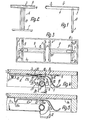
- Fig. 1 ein Ausschnitt eines mit einem erfindungsgemäßen Klapp-Beschlag versehenen Tisches in Ansicht auf eine Längsseite,
- Fig. 2 der Tisch gemäß Fig. 1 in Ansicht auf die Schmalseite,
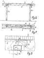
- Fig. 3 der Tisch gemäß Fig. 1 in Ansicht auf die Unterseite, jedoch in Aufbewahrungsstellung,
- Fig. 4 ein Ausschnitt der Fig. 1 im Vertikalschnitt durch den Beschlag in Gebrauchsstellung,
- Fig. 5 eine abgewandelte Ausführungsform des Beschlages in einer Darstellung entsprechend Fig. 4, jedoch in Aufbewahrungsstellung,
- Fig. 6 schematische Seitenansichten einer weiteren Variante und 7 (aufgestellt und zusammengeklappt),
- Fig. 8 ein Detail aus Fig. 6,
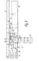
- Fig. 9 eine weitere Ausführungsform eines Beschlages in einer Darstellung entsprechend Fig. 4,
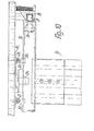
- Fig.10 der Beschlag gemäß Fig. 9 in teilweise geschnittener Ansicht von rechts.
- 1 is a detail of a table provided with a folding fitting according to the invention in a view of a long side,
- 2 the table of FIG. 1 in view of the narrow side,
- 3 the table of FIG. 1 in a view of the underside, but in the storage position,
- 4 shows a detail of FIG. 1 in a vertical section through the fitting in the use position,
- 5 shows a modified embodiment of the fitting in a representation corresponding to FIG. 4, but in the storage position,
- 6 schematic side views of a further variant and 7 (set up and folded),
- 8 shows a detail from FIG. 6,
- 9 shows a further embodiment of a fitting in a representation corresponding to FIG. 4,
- 10 the fitting according to FIG. 9 in a partially sectioned view from the right.
Wie die Figuren 1 bis 3 zeigen, weist der dargestellteAs shown in Figures 1 to 3, the one shown
Tisch 2 eine länglich rechteckige Tischplatte 3 mit vierTable 2 an elongated
Randzargen 4,5 auf, die ununterbrochen im Bereich aller Längskanten der Tischplatte 3 an deren Unterseite befestigt und gegenüber der Plattendicke der Tischplatte 3 geringfügig höher sind. Die Tischplatte kann jede beliebige, beispielsweise quadratische oder runde Form haben. Benachbart zu den an den Schmalseiten der Tischplatte 3 liegenden Randzargen 5 und parallel zu diesen ist jeweils ein Klapp-Beschlag 1 für jeweils ein annähernd T-förmiges Tisch-Bein 6 vorgesehen, dessen T-Quersteg 7 in Gebrauchsstellung des Tisch-Beines 6 an dessen unteren Ende horizontal liegt und die Standfläche des Beines 6 bildet. Der T-Fußsteg jedes Tisch-Beines 6 ist durch zwei parallele Holme 8 gebildet, die beiderseits in der Mitte des Quersteges 7 unmittelbar benachbart zueinanderliegen - und in Gebrauchsstellung vertikal stehen. Am oberen Ende des Tisch-Beines 6 ist jeweils eine zum Quersteg 7 bzw. zur Tischplatte 3 parallele Lagerstange 9 befestigt, die benachbart zur zugehörigen Schmalseite der Tischplatte 3 bzw. zur zugehörigen Randzarge 5 liegt und annähernd über das ganze zugehörige Kantenmaß der Tischplatte 3 reicht. Die Lagerstange 9 ist mit ihren Enden in nicht näher dargestellten, an den Innenseiten der Randzargen 4 vorgesehenen Schwenklagern gelagert, zwischen welchen die Lagerstange 9 in Richtung der mit ihrer Mittelachse zusammenfallenden Schwenkachse 10 im wesentlichen spielfrei gehalten ist. Die durchgehend gerade Lagerstange 9 ist im dargestellten Ausführungsbeispiel durch einen Rohrabschnitt von einem Außendurchmesser gebildet, der geringfügig kleiner als der Außendurchmesser der Holme 8 ist. Der Abstand der Schwenkachse 10 von der durch die Unterseite der Tischplatte 3 gebildeten Befestigungsebene für den Beschlag entspricht nur etwa dem eineinhalbfachen des Durchmessers der Lagerstange 9, derart, daß deren Unterseite mit nur sehr geringem Abstand oberhalb des Niveaus der Unterkanten der Randzargen 4,5 liegt. Die Anordnung ist jedoch so getroffen, daß in Aufbewahrungsstellung gemäß Figur 5 die Tisch-Beine 6 nach unten bis höchstens an die Ebene der Unterseiten der Randzargen 4,5 reichen, vorzugsweise gegenüber dieser Ebene geringfügig nach oben versetzt und dadurch vollständig innerhalb des durch die Randzargen 4,5 begrenzten Raumes aufgenommen sind.
Der in Figur 4 dargestellte Beschlag 1 weist eine im wesentlichen durchgehend ebene, mit ihrer Oberseite flach an der Unterseite der Tischplatte 3 anliegende und an dieser beispielsweise mit Schrauben befestigte, plattenförmige Konsole 11 aus Stahlblech auf, die im wesentlichen über die Länge der Lagerstange 9 reichen und auch deren Schwenklager tragen kann. Unmittelbar unterhalb der Konsole 11 und im wesentlichen ebenenparallel zu dieser ist ein im wesentlichen durchgehend ebenes, plattenförmiges und ebenfalls aus Stahlblech bestehendes Arretierglied 12 vorgesehen, das im Bereich seines zur zugehörigen Randzarge 5 benachbarten Endes zwei entgegengesetzt weisende, zu seiner Ebene und zu seiner Längsrichtung rechtwinklige Rastflächen 13,14 aufweist, die durch die beiden zur Schwenkachse 10 etwa parallelen Kantenflächen eines Steges des Arretiergliedes 12 gebildet sind, welcher von zwei benachbarten, fensterartig umschlossenen öffnungen 15,16 im Arretierglied 12 begrenzt ist. Die beiden Rastflächen 13,14 liegen im wesentlichen symmetrisch beiderseits der vertikalen Axialebene der zugehörigen Schwenkachse 10 in einem Abstand voneinander, der kleiner als der Durchmesser der Lagerstange 9, vorzugsweise nur etwa halb so groß ist. Das von den Rastflächen 13,14 und der benachbarten Randzarge 5 entfernt liegende Ende des Arretiergliedes 12 ist mit einem zur Schwenkachse 10 parallelen Lagerbolzen 17 in zwei aus der Konsole 11 nach unten gebogenen Seitenwangen 18 nach Art eines einarmigen Hebels um eine zu seiner Ebene parallele und zu seiner Längsrichtung rechtwinklige Achse schwenkbar gelagert.The fitting 1 shown in FIG. 4 has a substantially continuous flat plate-shaped
Dieses Ende des Arretiergliedes 12 liegt etwa um seine Plattendicke unterhalb der Konsole 11 tangential an der Oberseite des Lagerbolzens 17 an und ist an diesem zum Beispiel mit Schweißnähten befestigt. Das andere Ende des Arretiergliedes 12 geht unmittelbar benachbart zur von der Lagerung des Arretiergliedes 12 weiter entfernten Öffnung 16 in eine einteilig mit dem Arretierglied 12 ausgebildete Handhabe 19 über, welche im Anschluß an die Öffnung 16 S-förmig zunächst von der Konsole 11 nach unten weg und dann teilkreisförmig zurückgebogen ist, derart, daß die Handhabe 19 bis etwa an das Niveau der Unterkanten der Randzargen 4,5 reicht und nahe benachbart zur Innenfläche der zugehörigen Randzarge 5 liegt. Zwischen der Konsole 11 bzw. der Unterseite der Tischplatte 3 und der Oberseite des Arretiergliedes 12 ist zwischen der Schwenklagerung des Arretiergliedes 12 und der näher bei dieser liegenden Öffnung 15, vorzugsweise unmittelbar benachbart zu dieser Öffnung 15 eine Blattfeder 20 vorgesehen, welche ständig unter Vorspannung gegen die Oberseite des Arretiergliedes 12 drückt und dadurch das Arretierglied 12 zu seiner Arretierstellung hin belastet.This end of the locking
In der Mitte der Länge der Lagerstange 9 bzw. zwischen den Befestigungen der Holme 8 ist an der Umfangsfläche der Lagerstange 9 ein block- bzw. scheibenförmiger massiver Rastkörper 21 befestigt, der eine um die Schwenkachse 10 nahezu halbkreisförmig gekrümmte Umfangsfläche aufweist, über welche eine teilkreisförmige Rastnocke 22 vorsteht. Die Rastnocke 22 bildet an ihren Bogenenden jeweils eine Sperrfläche 23 bzw. 24, welche in der jeweiligen Sperrstellung oberhalb der Lagerstange 9 in einer vertikalen Ebene liegt und sich an der zugehörigen Rastfläche 13 bzw. 14 des Arretiergliedes 12 abstützt. Hierbei greift der jeweils zugehörige Abschnitt der Rastnocke 22 in die zugehörige Öffnung 15 bzw. 16 ein, wobei er über die Oberseite des Arretiergliedes 12 nicht vorsteht, sondern die obere, an die Umfangsfläche 25 der Rastnocke 22 anschließende Begrenzungskante der jeweiligen Sperrfläche 23 bzw. 24 etwa in der Ebene der Oberseite des Arretiergliedes 12 liegt, das dann mit dem Steg zwischen den öffnungen auf der Übrigen, an die radial inneren Begrenzungskanten der Sperrflächen anschließenden Umfangsfläche 26 des Rastkörpers 21 ruht. Die beiden Sperrflächen 23, 24 sind um die Schwenkachse 10,im dargestellten AusfUhrungsbeispiel um 90°, nämlich um den Bogenwinkel gegeneinander versetzt, Uber welchen das jeweilige Tisch-Bein 6 zwischen der Gebrauchs- und der Aufbewahrungsstellung zu schwenken ist.In the middle of the length of the bearing
In der Gebrauchsstellung wird das Tisch-Bein 6 durch das Arretierglied 12 und das im wesentlichen durch den Rastkörper 21 gebildete Gegenglied 27 nur gegen die Schwenkrichtung Pfeil 28 gesperrt, die zur Aufbewahrungsstellung, also in Figur 4 rechtsdrehend gerichtet ist. Zur Sperrung gegen die andere Schwenkrichtung sind an der Lagerstange 9 benachbart zu deren Enden zwei starre Anschläge 30 vorgesehen, die durch nahezu rechtwinklig begrenzte Klötze gebildet sind. Eine Außenfläche jedes Anschlages 30 ist im wesentlicheh tangential und - bezogen auf die Gebrauchsstellung des Beines 6 - vertikal an der von der Lagerung des Arretiergliedes 12 abgekehrten Umfangsseite der Lagerstange 9 starr befestigt, wobei der Anschlag 30 nach oben so weit Uber die Lagerstange 9 vorsteht, daß seine obere horizontale Anschlagfläche 31 im wesentlichen ganzflächig an der Unterseite der Konsole 11 sperrend anliegt. Die zur Befestigungsfläche an der Lagerstange 9 parallele sowie von dieser abgekehrt liegende Fläche des Anschlages 30, die in Gebrauchsstellung vertikal und parallel zur Schwenkachse 10 steht, bildet in Aufbewahrungsstellung gemäß Figur 5 eine Stapelfläche 32, die mit einem vorbestimmten Abstand unterhalb der Unterkanten der Randzargen 4,5 parallel zur Tischplatte 3 liegt, so daß der zusammengeklappte Tisch mit vier Stapelflächen 32 von zwei Beschlägen 1 auf der Oberseite der darunter angeordneten Tischplatte schonend aufgelegt werden kann. In Gebrauchsstellung liegt der Anschlag 30 vollständig oberhalb der Unterkanten der Randzargen 4, 5.In the use position, the
Da das Gegenglied 27 etwa in der Mitte der Länge der Lagerstange 9 vorgesehen ist und zwei Anschläge beiderseits des Gegengliedes 27 und/oder benachbart zu den Enden der Lagerstange 9 liegen, ergibt sich in Gebrauchsstellung eine Art DreipunktAbstützung des Beines und dadurch ein weiter verbesserter Halt. Außerdem ist der die größte Höhe einnehmende Bereich des Beschlages auf die Mitte der Lagerstange 9 und damit in der Regel auf die Mitte der Breite der Unterseite des Tisches verlegt.Since the
Der Beschlag gemäß Figur 5 unterscheidet sich von demjenigen nach Figur 4 im wesentlichen dadurch, daß das Arretierglied 12a einteilig mit der Konsole 11a ausgebildet und durch eine aus der Konsole 11a herausgestanzte und -gebogene Zunge gebildet ist, die mit ihrem von den Rastflächen 13,14 abgekehrten Ende einteilig in die Konsole 11a übergeht. Als übergang ist eine Federwurzel 20a vorgesehen, welche im Querschnitt so geschwächt ist, daß sie einerseits ein Schwenken des Arretiergliedes 12a zwischen der Arretierstellung und der Ausrückstellung ermöglicht und andererseits so stark rückstellende Federkräfte ausübt, daß sie das Arretierglied 12a stets zur Arretierstellung hin zwingt. Die Federwurzel 20a ist im dargestellten Ausführungsbeispiel in Seitenansicht annähernd U-förmig, wobei das Ende eines Schenkels in die Konsole 11a und das Ende des anderen Schenkels in das Arretierglied 12a übergeht. Wie Figur 5 zeigt kann die der Aufbewahrungsstellung zugehörige Sperrfläche 24a der Rastnocke 22a gegenüber der Rastfläche 14 des Arretiergliedes 12a auch geringfügig schräggestellt sein, so daß sich ein selbsthemmender Keileffekt ergibt, durch welchen ein spiel- und damit klapperfreier Halt des Tischbeines in der Aufbewahrungsstellung sichergestellt ist. Die Höhe bzw. Länge der Tisch-Beine 6 kann so gewählt sein, daß sie gemäß Figur 3 in Aufbewahrungsstellung rechtwinklig zu den Schwenkachsen 10 im Abstand voneinander liegen oder, daß sie einander in der Aufbewahrungsstellung übergreifen.The fitting according to FIG. 5 differs from that according to FIG. 4 essentially in that the locking member 12a is formed in one piece with the bracket 11a and is formed by a tongue punched out and bent out of the bracket 11a, which with its locking surfaces 13, 14 opposite end merges in one piece into the console 11a. A
Die Figuren 6 bis 8 zeigen eine Variante, bei der der horizontale Abstand zwischen den beiden Beinen geringer ist als die zweifache Beinlänge. Daher schlagen im zusammengeklappten Zustand die beiden Beine übereinander. Dies wird dadurch bewerkstelligt, daß die Beine 6a, 6b an der Lagerstange 9a versetzt angebracht sind, und zwar, wie aus Fig. 6 zu erkennen, in beiden Fällen nach einer Seite (links) versetzt. Beim Zusammenklappen kommt dabei das rechte Bein 6b näher an die Unterseite der Tischplatte 3 heran, während das linke Bein 6a in eine Ebene klappt, die unterhalb des rechten Tischbeins 6b liegt. Die als Stapelpuffer dienenden Anschläge 30 sind so gemessen, daß ihre Stapelflächen 32 etwas unterhalb der Ebene des Beines 6a liegen, so daß, wie in Fig. 7 gezeigt, beim Stapeln der zusammengeklappten Tische aufeinander das Tischbein 6a über der Plattenoberfläche liegt und diese nicht beschädigen kann.Figures 6 to 8 show a variant in which the horizontal distance between the two legs is less than twice the leg length. Therefore, when folded, the two legs cross over each other. This is accomplished in that the legs 6a, 6b are mounted offset on the bearing rod 9a, namely, as can be seen from FIG. 6, in both cases offset to one side (left). When collapsing, the right leg 6b comes closer to the underside of the
Bei der dargestellten Ausführung ist die Lagerstange 9a ein Rechteckrohr, das, wie aus der Lage der Achse 10 zu erkennen ist, etwas exzentrisch angeordnet ist. Grundsätzlich kann die Lagerstange jeden beliebigen Querschnitt haben, der es ermöglicht, Tischbeine oder Holme beliebiger Form und Anzahl möglichst gut mit ihr zu verbinden. Die Tischbeine können beispielsweise nur einen schmalen oder vorzugsweise breiten Mittelholm besitzen oder es können auch an jeder Stange vier nahe den Außenkanten des Tisches angeordnete Einzelbeine vorhanden sein, die nicht durch einen Quersteg in Form einer Kufe miteinander verbunden sind.In the embodiment shown, the bearing rod 9a is a rectangular tube which, as can be seen from the position of the
Aus Fig. 8 ist zu sehen, daß bei im übrigen prinzipiell gleicher Ausbildung des Beschlages 1 der Anschlag 30 nicht mit seiner seitlichen Anschlagfläche 31 an der Konsole anzuliegen braucht, sondern daß dafür ein gesonderter Anschlag 33 vorgesehen ist, an dem die der Stapelfläche 32 gegenüberliegende Anschlagfläche 31a bei aufgestelltem Tisch anschlägt. Der Anschlag 33 ist an der Konsole 11 angebracht. Im übrigen gleicht die Ausführung nach den Figuren 6 bis 8 denen der übrigen Zeichnungsfiguren, und es werden gleiche Bezugszeichen verwendet.From Fig. 8 it can be seen that with the rest of the same design of the
Bei der Ausführungsform nach den Fig. 9 und 10 sind die Anschläge 30 c und die Stapelglieder 34 durch gesonderte Glieder gebildet, die an unterschiedlichen Längsabschnitten der Lagerstange 9 c angeordnet sind. Die Stapelglieder 34 liegen nahe an den Enden der Lagerstange 9 c , während die Anschläge 30c im Bereich der Konsole 11 c beiderseits benachbart zum Arretierglied 12 liegen. Dadurch ergibt sich einerseits eine breite Stapelabstützung und andererseits die Möglichkeit, die Konsole 11 c relativ schmal auszubilden. Die Gegenanschlagglieder 33c sind durch parallel zur Tischplatte 3 c verstellbare Stellschrauben gebildet, deren Endflächen die Anschlag-Gegenflächen für die Anschläge 30 c bilden. Für jeden Anschlag 30c ist ein gesondertes Gegenanschlagglied 33 c vorgesehen, das in seiner jeweiligen Justierlage z.B. durch eine Kontermutter festgesetzt werden kann. Zur Lagerung der Gegenanschlagglieder ist an der Konsole 11 c jeweils eine Lagermuffe 35 befestigt, die in einer Ausprägung der Konsole 11 c nach unten abstehend befestigt ist.In the embodiment according to FIGS. 9 and 10, the
Die durch schmale Klötze gebildeten Anschläge 30 c sind hinsichtlich ihrer von der Lagerstange 9 c abgekehrten Enden gegenüber der Achse der Lagerstange 9 c so angeordnet, daß sie aus der Gebrauchs- bzw. Anschlagstellung nur von der Tischplatte 3 c bzw. der Konsole 11 c wegschwenken können. Im dargestellten Ausführungsbeispiel liegt dabei die gesamte, die Anschlagfläche 31 c bildende Fläche jedes Anschlages 30 c in Anschlagstellung in der zur Unterseite der Tischplatte 3 c rechtwinkligen Axialebene der Lagerstange 9 c. Dadurch kann die von der Lagerstange 9 c abgekehrte Endfläche des Anschlages 30c so vorgesehen werden, daß sie in Anschlagstellung an der Unterseite der Konsole 11 c anliegt und die Konsole 11 c fest gegen die Tischeplatte 3 c preßt, wodurch eine weitere Sicherung der an der Tischplatte 3 c verschraubten Konsole 11 c gegen die auftretenden Belastungen erreicht wird. Die Befestigungsschrauben der Konsole 11 c brauchen daher nur deren Verrutschen gegenüber der Tischplatte 3 c zu verhindern. Die Stapelglieder 34 liegen etwa symmetrisch zu einer zu den Anschlagflächen 31 c rechtwinkligen Axialebene der Lagerstange 9 c.The stops 30 c formed by narrow blocks are arranged with respect to their ends facing away from the bearing rod 9 c relative to the axis of the bearing rod 9 c so that they pivot away from the use or stop position only from the table top 3 c or the console 11 c can. In the exemplary embodiment shown, the entire surface of each
Die Lagerung der jeweiligen Lagerstange 9 c erfolgt unabhängig von der Konsole 11 c in verhältnismäßig langen Lagerklötzen 36, die parallel zur jeweils zugehörigen Rahmenzarge 4 c und gegenüber dieser nach innen versetzt angeordnet sind. Die mit ihren Enden an der Innenseite der benachbarten Rahmenzarge 5 c sowie mit ihren oberen Längskanten an der Unterseite der Tischplatte 3 c befestigten Lagerklötze 36 sind gegen die Unterseite der Tischplatte 3 c geschraubt und geleimt, während sie endseitig an der benachbarten Rahmenzarge 5 c durch Verdübeln und Verleimen befestigt sind. Auftretende Kräfte werden so über Eck aufgenommen und verteilt. Die langen Lagerklötze 36 bewirken außerdem eine zusätzliche Versteifung der Tischplatte 3 c. Die Lagerklötze 36 weisen Lagerbohrungen mit Lagerbuchsen auf, in welche die Lagerstangen 9 c jeweils mit einem an ihrem Ende vorgesehenen, vorstehenden Lagerzapfen 37 drehbar eingreifen. Sind die Tisch-Beine 6 c so angeordnet, daß sie in der Aufbewahrungsstellung übereinander geklappt werden, so wird dasjenige Tisch-Bein, das zuerst eingeklappt wird, wie in Fig. 9 strichpunktiert angedeutet, geringfügig über seine zugehörige Arretierstellung hinaus gegen die Unterseite der Tischplatte 3 c geschwenkt, während das andere Tisch-Bein gegen die Unterseite des zuerst eingeklappten Tisch-Beines geschwenkt und so arretiert wird, daß es das zuerst eingeklappte Tisch-Bein sicher und im wesentlichen spielfrei festhält. Dabei ist es unerheblich, welches Tisch-Bein zuerst eingeklappt wird, da die genannte Wirkung wechselseitig zwischen beiden Tisch-Beinen 6 c gegeben ist. Trotzdem kann sich das zuerst eingeklappte Tisch-Bein nicht unbeabsichtigt aus seiner Arretierung lösen, da es daran durch die in das Arretierglied 12 c eingreifende Sperrfläche 24 c gehindert wird. Durch die erfindungsgemäße Ausbildung können die Lagerstangen 9 c durch einfache, über ihre gesamte Länge gerade Rohrstücke gebildet sein. Die beiderseits der Mitte des Beschlages liegenden Teile sind gleich ausgebildet.The storage of the respective bearing rod 9 c takes place independently of the bracket 11 c in relatively long bearing blocks 36, which are arranged parallel to the associated frame frame 4 c and offset inwards relative to this. The bearing blocks 36 fastened with their ends to the inside of the adjacent frame frame 5 c and with their upper longitudinal edges to the underside of the table top 3 c are screwed and glued to the underside of the table top 3 c, while they are attached to the adjacent frame frame 5 c by dowelling and gluing are attached. Forces occurring are like this picked up and distributed around the corner. The long bearing blocks 36 also cause additional stiffening of the table top 3 c. The bearing blocks 36 have bearing bores with bearing bushes in which the bearing rods 9 c each rotatably engage with a protruding
Claims (11)
Priority Applications (1)
| Application Number | Priority Date | Filing Date | Title |
|---|---|---|---|
| AT85112195T ATE54804T1 (en) | 1984-10-04 | 1985-09-26 | FOLDING FITTING. |
Applications Claiming Priority (2)
| Application Number | Priority Date | Filing Date | Title |
|---|---|---|---|
| DE19843436358 DE3436358A1 (en) | 1984-10-04 | 1984-10-04 | FOLDING FITTING |
| DE3436358 | 1984-10-04 |
Publications (3)
| Publication Number | Publication Date |
|---|---|
| EP0176955A2 true EP0176955A2 (en) | 1986-04-09 |
| EP0176955A3 EP0176955A3 (en) | 1987-05-27 |
| EP0176955B1 EP0176955B1 (en) | 1990-07-25 |
Family
ID=6247048
Family Applications (1)
| Application Number | Title | Priority Date | Filing Date |
|---|---|---|---|
| EP85112195A Expired - Lifetime EP0176955B1 (en) | 1984-10-04 | 1985-09-26 | Fitting for a pivotable leg |
Country Status (3)
| Country | Link |
|---|---|
| EP (1) | EP0176955B1 (en) |
| AT (1) | ATE54804T1 (en) |
| DE (2) | DE3436358A1 (en) |
Cited By (9)
| Publication number | Priority date | Publication date | Assignee | Title |
|---|---|---|---|---|
| EP0256610A2 (en) * | 1986-08-04 | 1988-02-24 | Tabervall, S.A. | A collapsible desk |
| US5421272A (en) * | 1992-11-20 | 1995-06-06 | Globe Business Furniture, Inc. | Folding table |
| US5845589A (en) * | 1995-05-31 | 1998-12-08 | Pfister; Joel W. | Folding table leg system |
| US6394005B1 (en) | 2000-07-28 | 2002-05-28 | Valley Design Enterprises, Inc. | Articulating locking mechanism |
| EP1498047A1 (en) * | 2003-07-15 | 2005-01-19 | Brunner GmbH | Folding table |
| EP1552766A1 (en) * | 2004-01-09 | 2005-07-13 | Hiller Objektmöbel GmbH & Co. KG | Folding table |
| USD879514S1 (en) | 2018-04-16 | 2020-03-31 | Playground Store Limited | Desk |
| USD895325S1 (en) | 2018-04-16 | 2020-09-08 | Playground Store Limited | Desktop with stowed legs |
| US11051611B2 (en) | 2018-04-16 | 2021-07-06 | Playground Store Limited | Desk system |
Families Citing this family (5)
| Publication number | Priority date | Publication date | Assignee | Title |
|---|---|---|---|---|
| DE19741743C2 (en) * | 1997-09-22 | 2000-11-16 | Kusch Co Sitzmoebel | Folding table fitting |
| ITMI20010361A1 (en) * | 2001-02-23 | 2002-08-23 | Drake Corp | DEVICE TO STABILIZE THE STACKING OF A TABLE WITH FOLDING LEGS |
| DE10313024A1 (en) * | 2003-03-24 | 2004-10-07 | FÖRDERREUTHER, Bruno | Table with two foldable leg elements |
| WO2018081415A1 (en) | 2016-10-27 | 2018-05-03 | Steelcase Inc. | Flip top table |
| DE102018128798B3 (en) | 2018-11-16 | 2019-12-19 | Dürr Assembly Products GmbH | MEASURING ARRANGEMENT FOR CHECKING THE TRACK ANGLE OF A MOTOR VEHICLE IN A COORDINATE SYSTEM OF A WHEEL RECEPTION, METHOD FOR CALIBRATING THE MEASURING ARRANGEMENT AND METHOD FOR SUPPORTING THE ADJUSTMENT OF THE ADJUSTMENT OF THE ADJUSTMENT OF A WHEEL ADJUSTMENT |
Citations (4)
| Publication number | Priority date | Publication date | Assignee | Title |
|---|---|---|---|---|
| GB728852A (en) * | 1952-12-04 | 1955-04-27 | Sydney Schreiber | Improvements in or relating to hinges |
| DE1654640B1 (en) * | 1967-01-06 | 1971-12-09 | Benedikt Lienert | Folding table |
| DE2508726A1 (en) * | 1975-02-28 | 1976-09-09 | Kusch Co Sitzmoebel | Collapsible table with fold up legs - has swivel locking fitment folding flat when closing down table |
| CH632654A5 (en) * | 1979-09-03 | 1982-10-29 | Belform Basel Ag | Folding table |
Family Cites Families (2)
| Publication number | Priority date | Publication date | Assignee | Title |
|---|---|---|---|---|
| CH584524A5 (en) * | 1974-09-06 | 1977-02-15 | Fehlbaum Fa | |
| DE3229210C1 (en) * | 1982-08-05 | 1984-04-26 | Kusch & Co Sitzmöbelwerke KG, 5789 Hallenberg | Folding table fitting |
-
1984
- 1984-10-04 DE DE19843436358 patent/DE3436358A1/en active Granted
-
1985
- 1985-09-26 AT AT85112195T patent/ATE54804T1/en not_active IP Right Cessation
- 1985-09-26 DE DE8585112195T patent/DE3578854D1/en not_active Expired - Lifetime
- 1985-09-26 EP EP85112195A patent/EP0176955B1/en not_active Expired - Lifetime
Patent Citations (4)
| Publication number | Priority date | Publication date | Assignee | Title |
|---|---|---|---|---|
| GB728852A (en) * | 1952-12-04 | 1955-04-27 | Sydney Schreiber | Improvements in or relating to hinges |
| DE1654640B1 (en) * | 1967-01-06 | 1971-12-09 | Benedikt Lienert | Folding table |
| DE2508726A1 (en) * | 1975-02-28 | 1976-09-09 | Kusch Co Sitzmoebel | Collapsible table with fold up legs - has swivel locking fitment folding flat when closing down table |
| CH632654A5 (en) * | 1979-09-03 | 1982-10-29 | Belform Basel Ag | Folding table |
Cited By (10)
| Publication number | Priority date | Publication date | Assignee | Title |
|---|---|---|---|---|
| EP0256610A2 (en) * | 1986-08-04 | 1988-02-24 | Tabervall, S.A. | A collapsible desk |
| EP0256610A3 (en) * | 1986-08-04 | 1989-11-08 | Tabervall, S.A. | A collapsible desk |
| US5421272A (en) * | 1992-11-20 | 1995-06-06 | Globe Business Furniture, Inc. | Folding table |
| US5845589A (en) * | 1995-05-31 | 1998-12-08 | Pfister; Joel W. | Folding table leg system |
| US6394005B1 (en) | 2000-07-28 | 2002-05-28 | Valley Design Enterprises, Inc. | Articulating locking mechanism |
| EP1498047A1 (en) * | 2003-07-15 | 2005-01-19 | Brunner GmbH | Folding table |
| EP1552766A1 (en) * | 2004-01-09 | 2005-07-13 | Hiller Objektmöbel GmbH & Co. KG | Folding table |
| USD879514S1 (en) | 2018-04-16 | 2020-03-31 | Playground Store Limited | Desk |
| USD895325S1 (en) | 2018-04-16 | 2020-09-08 | Playground Store Limited | Desktop with stowed legs |
| US11051611B2 (en) | 2018-04-16 | 2021-07-06 | Playground Store Limited | Desk system |
Also Published As
| Publication number | Publication date |
|---|---|
| EP0176955B1 (en) | 1990-07-25 |
| DE3578854D1 (en) | 1990-08-30 |
| DE3436358C2 (en) | 1989-01-26 |
| DE3436358A1 (en) | 1986-04-10 |
| EP0176955A3 (en) | 1987-05-27 |
| ATE54804T1 (en) | 1990-08-15 |
Similar Documents
| Publication | Publication Date | Title |
|---|---|---|
| DE19607060C1 (en) | Seat for motor vehicle, especially rear seat, or rear bench seat | |
| DE2624429B2 (en) | Clamping means | |
| EP0176955B1 (en) | Fitting for a pivotable leg | |
| EP0082436A2 (en) | Vehicle seat | |
| EP0198056B1 (en) | Seat support for chairs, especially for rotating work-chairs | |
| DE102021200670A1 (en) | TABLE SAW INCLUDING A FOLDING TABLE EXTENSION | |
| DE19626025A1 (en) | Seat slide mechanism | |
| EP0065036B1 (en) | Table with adjustable top | |
| DE4304597C1 (en) | Cushion support frame for vehicle seat - has support members joined by spring loaded swivel mechanism with smallest force exerted in lowest position and increasing to highest position | |
| CH675060A5 (en) | ||
| DE102005044132C5 (en) | Fastening system with tension lock for attaching a piece of luggage to a bicycle rack | |
| DE19931953A1 (en) | Mounting for end of slat on longitudinal strut in frame comprises base mounting attached to longitudinal strut, slide attached to this and to support for slat, and locking device including movable clip which fits free side of mounting | |
| DE3227351C2 (en) | Locking device for two pairs of rails in a vehicle seat | |
| DE4102312C2 (en) | Seat rail for vehicle seats, in particular for motor vehicle seats | |
| DE202007002775U1 (en) | Table furniture with swiveling table top | |
| DE2004504B2 (en) | Vehicle sliding seat adjuster - has driving worm mounted on pivoted shaft and biassed into mesh with rack by spring | |
| DE2656543C2 (en) | Adjustable hinge | |
| EP0043102B1 (en) | Easily separable hinge for sideboards of freight vehicles | |
| EP0241859B1 (en) | Centre board for a surf board | |
| DE2638603A1 (en) | Writing desk for child - has hinged writing surface locked in required position by ratchet | |
| DE10044488B4 (en) | Chair with height-adjustable seat | |
| DE3151018A1 (en) | Vehicle seat, in particular motor vehicle seat | |
| DE4305209C1 (en) | Wallpapering table with scissor legs - has slides in hollow profiled frame members with trunnions for hinging legs and locked by spring-loaded components | |
| DE4208819C2 (en) | Wedge adjuster for fine and fine stone settings | |
| DE2700464C2 (en) | Recessed fitting |
Legal Events
| Date | Code | Title | Description |
|---|---|---|---|
| PUAI | Public reference made under article 153(3) epc to a published international application that has entered the european phase |
Free format text: ORIGINAL CODE: 0009012 |
|
| AK | Designated contracting states |
Kind code of ref document: A2 Designated state(s): AT BE DE FR NL |
|
| PUAL | Search report despatched |
Free format text: ORIGINAL CODE: 0009013 |
|
| AK | Designated contracting states |
Kind code of ref document: A3 Designated state(s): AT BE DE FR NL |
|
| 17P | Request for examination filed |
Effective date: 19870516 |
|
| 17Q | First examination report despatched |
Effective date: 19880127 |
|
| GRAA | (expected) grant |
Free format text: ORIGINAL CODE: 0009210 |
|
| AK | Designated contracting states |
Kind code of ref document: B1 Designated state(s): AT BE DE FR NL |
|
| REF | Corresponds to: |
Ref document number: 54804 Country of ref document: AT Date of ref document: 19900815 Kind code of ref document: T |
|
| ET | Fr: translation filed | ||
| REF | Corresponds to: |
Ref document number: 3578854 Country of ref document: DE Date of ref document: 19900830 |
|
| PLBE | No opposition filed within time limit |
Free format text: ORIGINAL CODE: 0009261 |
|
| STAA | Information on the status of an ep patent application or granted ep patent |
Free format text: STATUS: NO OPPOSITION FILED WITHIN TIME LIMIT |
|
| 26N | No opposition filed | ||
| PGFP | Annual fee paid to national office [announced via postgrant information from national office to epo] |
Ref country code: FR Payment date: 19910916 Year of fee payment: 7 |
|
| PGFP | Annual fee paid to national office [announced via postgrant information from national office to epo] |
Ref country code: AT Payment date: 19910924 Year of fee payment: 7 |
|
| PGFP | Annual fee paid to national office [announced via postgrant information from national office to epo] |
Ref country code: NL Payment date: 19910930 Year of fee payment: 7 |
|
| PGFP | Annual fee paid to national office [announced via postgrant information from national office to epo] |
Ref country code: BE Payment date: 19911003 Year of fee payment: 7 |
|
| PGFP | Annual fee paid to national office [announced via postgrant information from national office to epo] |
Ref country code: DE Payment date: 19911128 Year of fee payment: 7 |
|
| PG25 | Lapsed in a contracting state [announced via postgrant information from national office to epo] |
Ref country code: AT Effective date: 19920926 |
|
| PG25 | Lapsed in a contracting state [announced via postgrant information from national office to epo] |
Ref country code: BE Effective date: 19920930 |
|
| BERE | Be: lapsed |
Owner name: VS VEREINIGTE SPEZIALMOBELFABRIKEN VERMALTUNGS-G. Effective date: 19920930 |
|
| PG25 | Lapsed in a contracting state [announced via postgrant information from national office to epo] |
Ref country code: NL Effective date: 19930401 |
|
| NLV4 | Nl: lapsed or anulled due to non-payment of the annual fee | ||
| PG25 | Lapsed in a contracting state [announced via postgrant information from national office to epo] |
Ref country code: FR Effective date: 19930528 |
|
| PG25 | Lapsed in a contracting state [announced via postgrant information from national office to epo] |
Ref country code: DE Effective date: 19930602 |
|
| REG | Reference to a national code |
Ref country code: FR Ref legal event code: ST |