EP0177564B1 - Method and apparatus for filtration - Google Patents
Method and apparatus for filtration Download PDFInfo
- Publication number
- EP0177564B1 EP0177564B1 EP85901785A EP85901785A EP0177564B1 EP 0177564 B1 EP0177564 B1 EP 0177564B1 EP 85901785 A EP85901785 A EP 85901785A EP 85901785 A EP85901785 A EP 85901785A EP 0177564 B1 EP0177564 B1 EP 0177564B1
- Authority
- EP
- European Patent Office
- Prior art keywords
- membrane
- spinner
- gap
- filtrate
- blood
- Prior art date
- Legal status (The legal status is an assumption and is not a legal conclusion. Google has not performed a legal analysis and makes no representation as to the accuracy of the status listed.)
- Expired - Lifetime
Links
- 238000000034 method Methods 0.000 title claims abstract description 38
- 238000001914 filtration Methods 0.000 title claims abstract description 34
- 239000012528 membrane Substances 0.000 claims abstract description 158
- 239000000706 filtrate Substances 0.000 claims abstract description 41
- 238000000605 extraction Methods 0.000 claims abstract description 27
- 239000000725 suspension Substances 0.000 claims abstract description 19
- 239000006194 liquid suspension Substances 0.000 claims abstract description 12
- 210000004369 blood Anatomy 0.000 claims description 68
- 239000008280 blood Substances 0.000 claims description 68
- 230000009471 action Effects 0.000 claims description 32
- 239000011148 porous material Substances 0.000 claims description 26
- 230000004907 flux Effects 0.000 claims description 16
- 239000000470 constituent Substances 0.000 claims description 14
- 230000033001 locomotion Effects 0.000 claims description 13
- 230000001413 cellular effect Effects 0.000 claims description 11
- 239000012530 fluid Substances 0.000 claims description 10
- 238000010408 sweeping Methods 0.000 claims description 10
- 230000004087 circulation Effects 0.000 claims description 8
- 230000009467 reduction Effects 0.000 claims description 8
- 230000005484 gravity Effects 0.000 claims description 6
- 230000002829 reductive effect Effects 0.000 claims description 6
- 241001012508 Carpiodes cyprinus Species 0.000 claims description 5
- 238000004140 cleaning Methods 0.000 claims description 4
- 230000006378 damage Effects 0.000 claims description 3
- 239000012503 blood component Substances 0.000 claims description 2
- 239000003795 chemical substances by application Substances 0.000 claims description 2
- 239000012141 concentrate Substances 0.000 claims description 2
- 230000008021 deposition Effects 0.000 abstract description 19
- 230000008859 change Effects 0.000 abstract description 3
- 230000008569 process Effects 0.000 abstract description 2
- 210000004027 cell Anatomy 0.000 description 72
- 238000002616 plasmapheresis Methods 0.000 description 14
- 238000000926 separation method Methods 0.000 description 13
- 238000005534 hematocrit Methods 0.000 description 12
- 206010018910 Haemolysis Diseases 0.000 description 10
- 239000000306 component Substances 0.000 description 10
- 230000000694 effects Effects 0.000 description 10
- 230000008588 hemolysis Effects 0.000 description 10
- 230000007423 decrease Effects 0.000 description 6
- 238000004458 analytical method Methods 0.000 description 5
- 238000005374 membrane filtration Methods 0.000 description 5
- 210000002966 serum Anatomy 0.000 description 5
- 239000000853 adhesive Substances 0.000 description 4
- 230000001070 adhesive effect Effects 0.000 description 4
- 230000008901 benefit Effects 0.000 description 4
- 230000017531 blood circulation Effects 0.000 description 4
- 230000005779 cell damage Effects 0.000 description 4
- 208000037887 cell injury Diseases 0.000 description 4
- 102000004169 proteins and genes Human genes 0.000 description 4
- 108090000623 proteins and genes Proteins 0.000 description 4
- XLYOFNOQVPJJNP-UHFFFAOYSA-N water Substances O XLYOFNOQVPJJNP-UHFFFAOYSA-N 0.000 description 4
- 239000003146 anticoagulant agent Substances 0.000 description 3
- 229940127219 anticoagulant drug Drugs 0.000 description 3
- 230000003190 augmentative effect Effects 0.000 description 3
- 238000005516 engineering process Methods 0.000 description 3
- 230000006870 function Effects 0.000 description 3
- 230000006872 improvement Effects 0.000 description 3
- 238000011835 investigation Methods 0.000 description 3
- 239000007788 liquid Substances 0.000 description 3
- 230000007246 mechanism Effects 0.000 description 3
- 239000000203 mixture Substances 0.000 description 3
- 239000000047 product Substances 0.000 description 3
- 239000007787 solid Substances 0.000 description 3
- 238000009987 spinning Methods 0.000 description 3
- 230000003068 static effect Effects 0.000 description 3
- 230000001225 therapeutic effect Effects 0.000 description 3
- FAPWRFPIFSIZLT-UHFFFAOYSA-M Sodium chloride Chemical compound [Na+].[Cl-] FAPWRFPIFSIZLT-UHFFFAOYSA-M 0.000 description 2
- 230000004888 barrier function Effects 0.000 description 2
- 210000000601 blood cell Anatomy 0.000 description 2
- 210000001772 blood platelet Anatomy 0.000 description 2
- 238000004364 calculation method Methods 0.000 description 2
- 238000005119 centrifugation Methods 0.000 description 2
- 230000008878 coupling Effects 0.000 description 2
- 238000010168 coupling process Methods 0.000 description 2
- 238000005859 coupling reaction Methods 0.000 description 2
- 230000001419 dependent effect Effects 0.000 description 2
- 230000001066 destructive effect Effects 0.000 description 2
- 238000006073 displacement reaction Methods 0.000 description 2
- 210000003743 erythrocyte Anatomy 0.000 description 2
- 238000002474 experimental method Methods 0.000 description 2
- 238000005194 fractionation Methods 0.000 description 2
- 230000000670 limiting effect Effects 0.000 description 2
- 230000005012 migration Effects 0.000 description 2
- 238000013508 migration Methods 0.000 description 2
- 230000002572 peristaltic effect Effects 0.000 description 2
- 229920002492 poly(sulfone) Polymers 0.000 description 2
- 238000011084 recovery Methods 0.000 description 2
- 239000012487 rinsing solution Substances 0.000 description 2
- 238000013517 stratification Methods 0.000 description 2
- 239000000126 substance Substances 0.000 description 2
- 239000004677 Nylon Substances 0.000 description 1
- 230000001464 adherent effect Effects 0.000 description 1
- 238000002617 apheresis Methods 0.000 description 1
- 238000013459 approach Methods 0.000 description 1
- 239000007900 aqueous suspension Substances 0.000 description 1
- 238000010923 batch production Methods 0.000 description 1
- 230000009286 beneficial effect Effects 0.000 description 1
- 230000015572 biosynthetic process Effects 0.000 description 1
- 230000000903 blocking effect Effects 0.000 description 1
- 230000036770 blood supply Effects 0.000 description 1
- 230000020411 cell activation Effects 0.000 description 1
- 230000012292 cell migration Effects 0.000 description 1
- 210000003850 cellular structure Anatomy 0.000 description 1
- 238000004891 communication Methods 0.000 description 1
- 238000005094 computer simulation Methods 0.000 description 1
- 238000012790 confirmation Methods 0.000 description 1
- 238000010276 construction Methods 0.000 description 1
- 238000011109 contamination Methods 0.000 description 1
- 239000013078 crystal Substances 0.000 description 1
- 238000013016 damping Methods 0.000 description 1
- 238000010612 desalination reaction Methods 0.000 description 1
- 230000001627 detrimental effect Effects 0.000 description 1
- 238000002405 diagnostic procedure Methods 0.000 description 1
- 238000010586 diagram Methods 0.000 description 1
- 230000003467 diminishing effect Effects 0.000 description 1
- 238000000635 electron micrograph Methods 0.000 description 1
- 239000000284 extract Substances 0.000 description 1
- 238000009472 formulation Methods 0.000 description 1
- 239000012634 fragment Substances 0.000 description 1
- 229910000078 germane Inorganic materials 0.000 description 1
- 239000012510 hollow fiber Substances 0.000 description 1
- 239000007943 implant Substances 0.000 description 1
- 208000014674 injury Diseases 0.000 description 1
- 230000001788 irregular Effects 0.000 description 1
- 238000005259 measurement Methods 0.000 description 1
- 239000011325 microbead Substances 0.000 description 1
- 239000008267 milk Substances 0.000 description 1
- 210000004080 milk Anatomy 0.000 description 1
- 235000013336 milk Nutrition 0.000 description 1
- 229920001778 nylon Polymers 0.000 description 1
- 210000000056 organ Anatomy 0.000 description 1
- 239000002245 particle Substances 0.000 description 1
- 239000013618 particulate matter Substances 0.000 description 1
- 230000010287 polarization Effects 0.000 description 1
- 239000004417 polycarbonate Substances 0.000 description 1
- 229920000515 polycarbonate Polymers 0.000 description 1
- 230000000717 retained effect Effects 0.000 description 1
- 230000002441 reversible effect Effects 0.000 description 1
- 239000013049 sediment Substances 0.000 description 1
- 238000010008 shearing Methods 0.000 description 1
- 239000000243 solution Substances 0.000 description 1
- 238000003860 storage Methods 0.000 description 1
- 239000013589 supplement Substances 0.000 description 1
- 239000004094 surface-active agent Substances 0.000 description 1
- 230000001360 synchronised effect Effects 0.000 description 1
- 238000012546 transfer Methods 0.000 description 1
- 230000008733 trauma Effects 0.000 description 1
- 230000000472 traumatic effect Effects 0.000 description 1
- 238000000108 ultra-filtration Methods 0.000 description 1
- 238000011179 visual inspection Methods 0.000 description 1
- 239000002699 waste material Substances 0.000 description 1
Images

Classifications
-
- A—HUMAN NECESSITIES
- A61—MEDICAL OR VETERINARY SCIENCE; HYGIENE
- A61M—DEVICES FOR INTRODUCING MEDIA INTO, OR ONTO, THE BODY; DEVICES FOR TRANSDUCING BODY MEDIA OR FOR TAKING MEDIA FROM THE BODY; DEVICES FOR PRODUCING OR ENDING SLEEP OR STUPOR
- A61M1/00—Suction or pumping devices for medical purposes; Devices for carrying-off, for treatment of, or for carrying-over, body-liquids; Drainage systems
- A61M1/34—Filtering material out of the blood by passing it through a membrane, i.e. hemofiltration or diafiltration
- A61M1/3496—Plasmapheresis; Leucopheresis; Lymphopheresis
-
- A—HUMAN NECESSITIES
- A61—MEDICAL OR VETERINARY SCIENCE; HYGIENE
- A61M—DEVICES FOR INTRODUCING MEDIA INTO, OR ONTO, THE BODY; DEVICES FOR TRANSDUCING BODY MEDIA OR FOR TAKING MEDIA FROM THE BODY; DEVICES FOR PRODUCING OR ENDING SLEEP OR STUPOR
- A61M1/00—Suction or pumping devices for medical purposes; Devices for carrying-off, for treatment of, or for carrying-over, body-liquids; Drainage systems
- A61M1/14—Dialysis systems; Artificial kidneys; Blood oxygenators ; Reciprocating systems for treatment of body fluids, e.g. single needle systems for hemofiltration or pheresis
- A61M1/16—Dialysis systems; Artificial kidneys; Blood oxygenators ; Reciprocating systems for treatment of body fluids, e.g. single needle systems for hemofiltration or pheresis with membranes
- A61M1/26—Dialysis systems; Artificial kidneys; Blood oxygenators ; Reciprocating systems for treatment of body fluids, e.g. single needle systems for hemofiltration or pheresis with membranes and internal elements which are moving
- A61M1/262—Dialysis systems; Artificial kidneys; Blood oxygenators ; Reciprocating systems for treatment of body fluids, e.g. single needle systems for hemofiltration or pheresis with membranes and internal elements which are moving rotating
- A61M1/265—Dialysis systems; Artificial kidneys; Blood oxygenators ; Reciprocating systems for treatment of body fluids, e.g. single needle systems for hemofiltration or pheresis with membranes and internal elements which are moving rotating inducing Taylor vortices
-
- B—PERFORMING OPERATIONS; TRANSPORTING
- B01—PHYSICAL OR CHEMICAL PROCESSES OR APPARATUS IN GENERAL
- B01D—SEPARATION
- B01D61/00—Processes of separation using semi-permeable membranes, e.g. dialysis, osmosis or ultrafiltration; Apparatus, accessories or auxiliary operations specially adapted therefor
- B01D61/02—Reverse osmosis; Hyperfiltration ; Nanofiltration
- B01D61/025—Reverse osmosis; Hyperfiltration
-
- B—PERFORMING OPERATIONS; TRANSPORTING
- B01—PHYSICAL OR CHEMICAL PROCESSES OR APPARATUS IN GENERAL
- B01D—SEPARATION
- B01D63/00—Apparatus in general for separation processes using semi-permeable membranes
- B01D63/06—Tubular membrane modules
- B01D63/062—Tubular membrane modules with membranes on a surface of a support tube
-
- B—PERFORMING OPERATIONS; TRANSPORTING
- B01—PHYSICAL OR CHEMICAL PROCESSES OR APPARATUS IN GENERAL
- B01D—SEPARATION
- B01D63/00—Apparatus in general for separation processes using semi-permeable membranes
- B01D63/16—Rotary, reciprocated or vibrated modules
-
- B—PERFORMING OPERATIONS; TRANSPORTING
- B01—PHYSICAL OR CHEMICAL PROCESSES OR APPARATUS IN GENERAL
- B01D—SEPARATION
- B01D65/00—Accessories or auxiliary operations, in general, for separation processes or apparatus using semi-permeable membranes
- B01D65/02—Membrane cleaning or sterilisation ; Membrane regeneration
-
- B—PERFORMING OPERATIONS; TRANSPORTING
- B01—PHYSICAL OR CHEMICAL PROCESSES OR APPARATUS IN GENERAL
- B01D—SEPARATION
- B01D2313/00—Details relating to membrane modules or apparatus
- B01D2313/48—Mechanisms for switching between regular separation operations and washing
-
- B—PERFORMING OPERATIONS; TRANSPORTING
- B01—PHYSICAL OR CHEMICAL PROCESSES OR APPARATUS IN GENERAL
- B01D—SEPARATION
- B01D2313/00—Details relating to membrane modules or apparatus
- B01D2313/90—Additional auxiliary systems integrated with the module or apparatus
-
- B—PERFORMING OPERATIONS; TRANSPORTING
- B01—PHYSICAL OR CHEMICAL PROCESSES OR APPARATUS IN GENERAL
- B01D—SEPARATION
- B01D2313/00—Details relating to membrane modules or apparatus
- B01D2313/90—Additional auxiliary systems integrated with the module or apparatus
- B01D2313/903—Integrated control or detection device
-
- B—PERFORMING OPERATIONS; TRANSPORTING
- B01—PHYSICAL OR CHEMICAL PROCESSES OR APPARATUS IN GENERAL
- B01D—SEPARATION
- B01D2315/00—Details relating to the membrane module operation
- B01D2315/02—Rotation or turning
-
- B—PERFORMING OPERATIONS; TRANSPORTING
- B01—PHYSICAL OR CHEMICAL PROCESSES OR APPARATUS IN GENERAL
- B01D—SEPARATION
- B01D2321/00—Details relating to membrane cleaning, regeneration, sterilization or to the prevention of fouling
- B01D2321/02—Forward flushing
Abstract
Description
- This invention relates to membrane filtration of matter from liquid suspensions, and particularly to biomedical applications of such technology. It is especially relevant to, but not limited to, the separation or fractionation of the constituents of blood.
- Techniques for the separation and collection of given constituents of whole blood are in wide use for many therapeutic, medical and experimental applications. Plasmapheresis (the separation of fluid plasma from the red and white cells of whole blood) forms the basis of widespread plasma storage and supply systems, and also is employed increasingly in therapeutic apheresis. Plasma is collected from individual donors by withdrawing whole blood, separating the plasma, and preferably returning high hematocrit (high cell percentage) fractions back to the donor. Plasmapheresis by centrifugal separation is widely used in laboratories but is essentially a batch process of limited convenience and commercial practicality. Continuous centrifugal separation is desired if plasma is to be collected rapidly and with minimum donor inconvenience, and in the modern state of the art this cannot be done at reasonable cost. Blood handling and collection systems must be completely sterile, which in effect requires that all elements in contact with the blood be low cost disposable components or devices. Many workers in the art have thus experimented with membrane filtration techniques, in which a membrane with suitably small pore size (e.g. 0.5 microns) is utilized to filter plasma from the blood. Because of the viscous and complex quality of whole blood, simple filtration does not suffice because deposition (clogging of pores with cellular matter) quickly decreases the efficiency of transfer through the membrane.
- Recognizing these problems, a number of workers in the art have sought to utilize the shear principles so as to increase efficiency. Transport of whole blood laterally across a membrane surface which is moving relative to an opposed surface sets up shearing forces on the blood sheet, tending to keep the cellular matter in motion and to lift it away from the membrane pores, substantially reducing the deposition problem. Workers in the art have observed a generally increasing relationship between the amount of shear and the efficiency of the filtration process, with an upper limit being imposed by unwanted cell disruption or hemolysis, typically at maximum shear rates of 7,500 to 10,000/sec with prior devices.
- Membrane filtration effectively appeared to have reached a practical limit with various flat membrane configurations, because of various pressure losses and flow discontinuities. In practice, a substantial membrane area has been required for such configurations, in order to enable plasma collection at a reasonable rate from an individual donor. However the membrane cost is high and the system efficiency decreases with the duration of usage. Thus the desirable objective of a low cost disposable has not been heretofore achieved with a reliably operating system.
- More recently, however, a remarkable advance in blood separation technology using membrane filtration has arisen from a different structure, described in EP-A-112152, filed 13.12.83, published 13.12.83 and claiming a priority of 13.12.82. The configuration described in that patent application provides filtration rates in excess of ten times that found in prior membrane filtration devices, for a given surface area. A membrane covered spinner, having an interior collection system, is disposed within a stationary shell, and blood is fed into the space between the spinner and the shell, moving both circumferentially about the shell and along the longitudinal axis to a spaced apart exit region. A practical device, having a gap of .030" (.076 cm) and a rotational velocity of approximately 3600 r.p.m., with a spinner diameter of 1" (2.54 cm) and length of 3" (7.5 cm) enables plasma to be derived at approximately 45 ml/min, and with high plasma recovery (e.g. in excess of 70%). A plasma recovery of 0.9 ml/cm2/min is achieved in contrast to prior art flat plate systems providing about 0.039 ml/cm2/min and hollow fiber systems providing 0.013 ml/cm2/min. The significant improvement in filtration efficiency thus afforded makes a low cost plasmapheresis disposable practical for the first time, and enables two to three units of blood to be transferred conveniently and quickly as high hematocrit remainder is returned to the donor.
- While flow conditions existing between a rotating spinner and a concentric shell have been much studied, being termed Couette flow, the extraction of a filtrate through a membrane on the spinner represents a special case of potentially wide applicability. Generically, this configuration encompasses a number of systems in which a filter member spinning within a bath is used to prevent or limit particulates in the bath from adhering to the filter, while drawing filtrate into the interior of the spinner. Particular examples of these are shown in an article by M. Lopez-Leiva entitled "Ultrafiltration at Low Degrees of Concentration Polarization: Technical Possibilities" in Desalination (Netherlands) Vol. 35, pp. 125-128 (1980) dealing with the concentration of milk products, and in Patent No. 4,184,952 (Shell Oil) dealing with the extraction of oil from basic sediment and water. However, there is nothing in these disclosures that would tend to indicate that the significant improvement achieved by Fischel in plasmapheresis would even be possible, or explain the mechanism of separation in such a system. The Fischel patent application as filed hypothesized that a "shear centrifugation" effect takes place, with centrifugal forces acting to cause migration of the cellular matter outwardly toward the stationary wall, while a plasma-rich layer resides at the surface. Limiting factors on the performance of this system were described in terms of conditions to maintain laminar flow between the spinner and the outer wall, while also exerting sufficient centrifugal force to achieve outward cell migration. Thus the application purported to distinguish from other rotating flow systems in which relative movement between two concentric cylinders causes creation of localized cellular structures, called Taylor vortices, between the walls.
- Taylor vortices also have been intensively investigated in the literature and a number of devices, particularly oxygenators proposed by Brumfield, in U.S. Patent Nos, 3,771,658, 3,771,899 and 4,212,741, have been considered that utilize such effects. Most of the investigations of Taylor vortices are concerned with theoretical aspects, and few systems, including the oxygenators, have been successfully implemented using these principles. No systems using Taylor vortices are known in which the dynamics of the fluid medium between the members are affected or altered by continuous extraction of constituents from the medium.
- European Patent Specification EP-A-0165992 (International Publication Number W085/02783) which has an earlier priority date than the present application but is not a prior publication, discloses a filtration- system having a gap defined between a rotary spinner and a housing, one of which carries a filter membrane. Taylor vortices are generated in the gap to prevent clogging of the membrane.
- The situation in which a filtrate is extracted from a complex fragile living system, such as whole blood, can be seen to involve many complex factors. It is shown hereafter that the operating mode in the Fischel system does not create laminar flow under the conditions stated above, and that the withdrawal of the plasma itself generates forces substantially in excess of the centrifugal forces acting on the blood cells. While the particular plasmapheresis system of Fischel functions with the efficiency described, further improvements as to the limits and optimums of the process are made feasible by the use of configurations and operating conditions which take into account all of the dominant system requirements to establish and enhance a substantially different mode of operation.
- In accordance with the present invention there is provided a method of filtering a liquid suspension passing through a radial gap between a spinner and a concentric shell without clogging a filter membrane disposed on one of the surfaces defining the gap comprising the steps of establishing a plurality of annular vortices in the liquid suspension about the spinner and adjacent the membrane by selection of the surface velocity of the spinner relative to the radial gap and the viscosity of the suspension; extracting filtrate through the membrane; sensing transmembrane pressure; comparing the transmembrane pressure to a threshold transmembrane pressure value for extraction with full membrane efficiency; and reducing the filtrate throughput while maintaining the vortex action to clean the membrane when the transmembrane pressure rises above the threshold pressure value. The invention also provides a system for carrying out this filtering method.
- In the method and system to be described an operating regime is established, in Couette-type flow, in which the radial gap, spinner diameter, and angular velocity are selected for a given liquid suspension to establish strong but controlled Taylor vortices along the length of the spinner. The strong vortex action creates a series of adjacent annular vortex cells about the spinner and moving along the length of the spinner while alternating in direction of internal circulation. The vortex action is strong enough for the cells to substantially fill the radial gap, and matter in suspension thus is impelled in a complex path having orthogonal velocity components at both the spinner and outer wall surfaces. In accordance with the invention, matter may be filtered via a surface membrane from either the inner (spinner) surface, the outer (stationary wall) surface, or both. The velocity components at the membrane surface contribute meaningfully to the high shear rate established by relative spinner-wall motion and provide an interior sweeping motion within the radial gap that tends to clear the membrane of matter that would otherwise deposit on the membrane pores as filtrate is rapidly extracted.
- Systems and methods in accordance with the invention are particularly useful in overcoming the many difficult problems of hemapheresis systems, but are equally well suited for a wide range of other applications. The concept appears useful whereever the aggregate viscosity of the system permits establishment of strong Taylor vortices over a length of spinner despite constant filtrate extraction, and the density of solid or particulate matter within the suspension allows entrainment of the matter within the circulating vortices.
- In a specific example of a filtration system and method, a vortex action is created that is well above the onset of Taylor cells but below levels at which destructive shear might occur. A membrane covered spinner having an internal filtrate collection system is separated from a concentric outer wall by a predetermined radial gap within which an augmented but substantially uniform vortex action is maintained despite filtrate extraction. Preferably the radial gap is selected to be near the upper end of the permissible range where shear and vortex forces are maximum with the other factors being adjusted accordingly. This insures that the velocity of extraction through the membrane, which tends to draw cells into the membrane, is more than counteracted by the orthogonal velocity components sweeping the membrane surface. The vortex action is not so vigorous that inward flow causes cell deposition on the membrane or outward flow causes excessive turbulence and destructive effects. The counter-rotating vortices constantly mix the matter in suspension, replenishing the supply of potential filtrate available at the membrane surface, adjacent each vortex cell. Moreover there is substantially constant advance of the cells from input to output, so that local static conditions cannot exist. Filtrate within the suspension is more mobile than the entrained cellular matter or solids and can be interchanged between vortex cells so as to tend to equalize filtrate extraction rates throughout the membrane.
- Under conditions of strong but controlled vortex circulation, the tangential flow velocities can advantageously be balanced for specific purposes against radial flow velocity through the membrane. In a plasmapheresis system, for example, the transmembrane pressure and the plasma throughput "% take") are readily determined by instrumentation devices and real time calculations. The transmembrane pressure relative to plasma throughput for a 100% efficient membrane is derived by analysis or empirical observation, to establish a reference identifying the onset of cell deposition. When the transmembrane pressure increases to or above the level at which cell deposition is imminent, separation systems in accordance with the invention reduce the filtrate throughput rate at least for a time. The consequent decrease in filtrate radial flow velocity allows the tangential flow components to free deposited cells or maintain efficiency, thus clearing the membrane and restoring system efficiency. No known filtration systems have this internal capability.
- Another feature of systems in accordance with the invention is that the surface topology of the membrane is selected relative to the nature of the suspension being filtered. To enhance the vortex action and minimize occlusion of membrane by blood, for example, a smooth surfaced membrane is employed that has surface irregularities no greater than the pore size. Despite the fact that membrane surface variations may be minute in many commercial membranes, they nonetheless can hemolyze and entrap red cells while diminishing the local surface effects of vortex action. Thus superior results are achieved by employing smooth surfaced membranes under these conditions.
- Other systems in accordance with the invention implant the filter membrane in the outer, stationary, wall with a number of constructional advantages and minimal reduction in operating efficiency. The stationary membrane surfaces may readily be replaced for use of the system as a separator for diagnostic applications, or for applications where the system is to be operated continuously for extended periods. In a specific example of this type of separator, the vortex flow is established by a spinner retained within a concentric split housing that can be opened to replace longitudinal filter membranes. An external magnetic drive rotates the spinner at an angular velocity that insures, relative to the gap and suspension viscosity, that strong vortices exist to provide sweeping action and freedom from clogging at the membrane. With a slightly lower extraction rate than used in an interior membrane system operating with a given spinner surface velocity, a high % take is nonetheless achieved. The velocity or gap dimension can be increased to provide a higher % take in many instances. The system has further advantages if used for diagnostic or analytical purposes because the membrane can be replaced and the unit can repeatedly be reused by rinsing the membrane between operations.
- A specific example of a system for providing superior plasmapheresis operation employs maximized gap spacings for a given rotational rate, together with Taylor numbers in the range of 70 to 250 and shear rates of 7500/sec to 10000/sec maximum. Among the further aspects of the invention, pore sizes can be used that are in the range of 0.8 to 1.0 microns, these being larger and more efficient that those heretofore used. In addition, blood flow through the separation device can be against gravity if desired for specific purposes. Inasmuch as minimal membrane area is desired for low cost plasmapheresis disposals, a relatively small range of gap sizes and angular velocities is employed for achieving maximized and constant throughput rates for plasma. For example, with a 1" (2.54 cm) diameter rotor the gap dimension is held in the range between about 0.018" (0.046 cm) and 0.030" (0.076 cm) for rotor angular velocities of 3000 to 3600 r.p.m.
- A better understanding of the invention may be had by reference to the following description, taken in conjunction with the accompanying drawings, in which:
- Fig. 1 is a combined perspective view, partially broken away and block diagram of a plasmapheresis system in accordance with the invention;
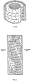
- Fig. 2 is an enlarged and simplified fragmentary perspective view of a part of the plasma separation device in the arrangement of Fig. 1, showing vortex flow characteristics;
- Fig. 3 is an enlarged side sectional view of the arrangement of Fig. 2, depicting vortex flow as described in the literature and as seen in operation;
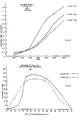
- Fig. 4 is a graph showing changes in plasma delivery for given input flow with changes in the relationship between gap and angular velocity for a given size spinner;
- Fig. 5 is a graph showing plasma flux changes for different gap sizes, other factors remaining constant;
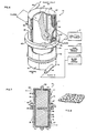
- Fig. 6 is a perspective view, partially broken away, of a different example of a system in accordance with the invention utilizing a stationary membrane;
- Fig. 7 is a side sectional view of the system of Fig. 6; and
- Fig. 8 is a perspective view, somewhat idealized and not to scale, of a fragment of a filtration membrane, showing the surface irregularities in one type of membrane.
- A
plasmapheresis system 10, referring now to Fig. 1, in which the elements have been depicted only generally, provides a particularly suitable example of a blood separation system in accordance with the invention. Whole blood is taken from a donor via a needle means 12, shown as a single needle although a double needle system may alternatively be used. Disposable tubing is utilized to conduct the blood from the donor, and to combine it with a flow of anticoagulant from a source 13 (flow control for the anticoagulant being of any one of a number of known types and therefore not shown). Aninput blood pump 14, such as a peristaltic or pressure roller device, feeds the combined flow, when actuated by an associatedblood pump control 16, to atransmembrane pressure sensor 18 and also to a disposableplasma separator device 20. Theplasma separator 20 is in the form of aspinner 22 havingmagnetic elements 23 integral with one end and rotatable about a central longitudinal axis within a stationary housing orshear wall 24. Thespinner 22 is receivable between a pair of positioning supports 25, 26 spaced apart along the central axis, and shown only generally. Theupper support 25, seen only in fragmentary form, provides a positioning seat for a non-rotating upper portion of theseparator device 20. At the upper end also a magnetic drive 27 (not shown in detail) encompassing and magnetically coupling to themagnetic elements 23 integral with the-spinner 22, is rotated by adrive motor 28. Thelower support 26 receives the lower end of thestationary housing 24 and defines an opening through which aplasma outlet 30 coaxial with the central axis may provide plasma as output. - The surface of the
spinner 22 may be covered by afilter membrane 40 of a type conventionally used in blood filtration, and having surface apertures in the range of 0.1 to 1.0 microns. In the present system, however, substantial advantages are obtained by using membranes having particularly physical characteristics and a pore size in the range of 0.8 to 1.0 microns, as described below. Under themembrane 40, the spinner surface is configured to define a plurality ofcircumferential grooves 42, interconnected by longitudinal grooves 44 which in turn communicate viaradial conduits 46 with a central manifold 48. The manifold 48 is in communication, through an end seal and bearing arrangement (not shown in detail) with theplasma outlet 30. - While blood from the donor is fed into the space between the
spinner 22 and inner wall of theconcentric housing 24 via atangential blood inlet 50 coupled by a flexible tubing (not shown in detail) to theblood input pump 16. A high hematocrit return flow is taken from atantential outlet orifice 52 spaced apart from the inlet along the longitudinal axis of theseparator device 20. Flexible tubing (also not shown in detail) couples theoutlet 52, through a peristalticpacked cell pump 53 operated by acontrol 54, to ahigh hematocrit reservoir 55.Separator 20 operation can thereby be isolated from the donor so that alternate pump and return cycles can be used with a single needle device. Packed cells are reinfused in the donor at the needle means by a return pump 56 in areturn line 57 between the needle means 12 and thereservoir 55. Areturn pump control 59 operates the return pump 56 at rates and times determined by the control system, which may include means (not shown) for sensing the level in thereservoir 55. - In the current state of the art, it is preferred to use a
microprocessor 61 to monitor various conditions and to establish various controls, so that a number of operating modes can be established and the system can operate automatically with a minimum of operator attention. Many such features are provided in a practical example of a system in accordance with the invention, but only aspects germane to the present concept will be described, and it will be recognized that these particular features can also be provided by direct manual controls. - The principal inputs to the
microprocessor 61, for purposes of the present description, are taken from the transmembrane pressure sensor coupled to the output of theblood input pump 14, and the flow rate for packed cell output established by the rate set at the packedcell pump control 54. The flow rates for the packed cell output are derived at themicroprocessor 61 by counting the number of revolutions at thepump 53. Other flow rates, and the motor speed if desired, can be fed back to themicroprocessor 61, but these need not be described here. - The
separator device 20, the mechanical operation of which is described in greater detail in the previously mentioned Fischel application, extracts plasma from the whole blood flow, through themembrane 40. The plasma flows through themembrane 40 into the circumferential andlongitudinal grooves 42, 44 on thespinner 22 surface and then into the central manifold 48 via theradial conduits 46. The collected plasma in the central manifold 48 passes through theplasma outlet 30 to aplasma collection bag 62. The typical donor supplies two to three units of plasma in thirty to forty-five minutes, this being a rate consistent with blood supply from and high hematocrit return to the donor, without discomfort or substantial danger. As noted in the Fischel application, the rate of extraction remains substantially constant. Under proper operation, the plasma is clear and golden in color, being essentially completely free of cell damage and consequent hemolysis. - It is, however, extremely important to achieve maximum reliable throughput of plasma, without trauma to the blood on the one hand or creation of a sensitive or unstable plasmapheresis procedure on the other. Further benefits can then be derived in terms of the efficiency of plasma extraction, possible reduction of the cost of the expensive filter membrane, and the amount of donor time that is required. In accordance with the present invention, applicant departs entirely from the view that a controlled laminar flow must be established, with stratification of a plasma rich layer at the membrane surface, and with outward radial migration of cellular matter in the blood. Instead, applicant induces a strong vorticity in the form of successive, alternately circulating, annuli about the spinner and occupying the gap between the spinner and the shear wall. This vortex action is of a type, referred to as Taylor vortices, first proposed by G. I. Taylor in 1923 and described by him in Phil. Trans. Am., Vol. 233, pp. 289-293 in "Stability of a Viscous Liquid Contained Between Two Rotating Cylinders". Prior theoretical and computer simulation studies of the Taylor phenomenon (of which there are many) posit that the flow that is created in a Couette structure, under proper conditions, establishes a continuous sequence of annular vortex cells along the longitudinal axis of the cylinder. As seen in the fragmentary and idealized views of Figs. 2 and 3, which are not to scale, each cell has a circulatory flow within the plane of a cross-section that is radial to the central (rotational) axis of the spinner, with the direction of circulation alternating between successive cells. The perspective view of Fig. 2 depicts the generally helical flows within an individual cell and the counter-rotation of alternate cells within the series. The sectional view of Fig. 3 represents a computer generated approximation of flows within a cross-section extending along the spinner axis and at some radius relative to the axis.
- The great majority of prior studies, however, have been of stable liquid system maintained under constant operating conditions. Proposals for practical utilization of the effect have heretofore been limited, although the theoretical investigations have been and remain extensive in character.
- The Taylor number, as it is now called, was defined by G. I. Taylor as the product of the Reynolds number and the square root of the gap between the rotor and housing divided by the square root of the radius of the rotor. The vortices begin to appear, superimposed on the tangential flow induced by the relative rotation, when the Taylor number is greater than 41.3. Many of the investigations in the past have induced relative movement by spinning either the housing or the central mandrel, or both. In the examples given hereafter, only the central mandrel is spun, although the
filter membrane 40 may be disposed on thespinner 22 surface or on the stationary cell. It is also feasible to utilize the vortex action and other flow conditions in a variety of other configurations and with other media, as discussed below. - Given the preferred example of the Fischel application, that of a 1" (2.54 cm) diameter spinner, 3600 r.p.m. rotation and a .027" (0.069 cm) gap, analysis has shown that the Fischel device actually operates in a region above the Taylor threshold. Using these operative parameters, stable and conventional laminar flow would not be established unless the gap dimension were reduced to as low as .010" (0.025 cm), at which value shear levels would be excessive (for the given rotational rate) and hemolysis would occur. A significant feature of applicant's invention is that vortex flow is not only permitted to occur, but is accentuated and strengthened by expansion of the vortex cell sizes to occupy substantially the entire gap region and to provide tangential movement at substantial velocity across the membrane surface.
- An important consideration, in accordance with the invention, is that the entire useful surface of the
membrane 40 is made to contribute to the extraction process even though the suspension changes constantly because of filtrate extraction. The vortex action is preferably augmented to the level at which the Taylor number is in. excess of 70, and more preferably in excess of 100, but usually not greater than about 250, throughout the length of the filter membrane despite the substantial increase in viscosity as plasma is extracted. Because the vortex cells fill the radial gap and sweep the membrane surface in closely tangential relationship, velocity and force components of substantial magnitude adjacent themembrane 40 surface are induced that are othogonal to the forces induced by rotation of thespinner 22. This circulating motion, coupled with convection along thespinner 22 axis, constantly seeks to remove any adherent cells from the surface of themembrane 40 and replenishes available plasma for filtration through the membrane pores. Any given point on themembrane 40 is swept in a time varying fashion by matter moving in alternately parallel and anti-parallel directions relative to the axis of rotation of the spinner. The circulatory forces that exist thus supplement the shear forces exerted on the blood by viscous drag, tangential to the spinningmembrane 40 surface. - At the same time, as seen in Fig. 3, constant interchanges between adjacent cells take place, for both plasma and cellular components, although the plasma probably is transported longitudinally more readily than is the cellular matter. The interchange tends to substantially diminish any hematocrit gradient across the gap adjacent the
spinner 22, although one can observe a color gradient increasing in intensity as one travels from the inlet to the outlet. Nonetheless the system achieves the desired effect of utilizing all incremental areas of theentire spinner 22 with substantially equal efficiency. Because the vortex cells are not static but are constantly moving downwardly toward theoutlet 52, any given incremental area on the membrane is sequentially exposed to different vortex forces, militating against tendencies toward buildup of cell deposition. The scrolling motion of the vortex cells as the blood mass moves causes the vortex cells to be angularly disposed or slanted relative to the central axis. - The circumferential rotation within the Taylor vortex cell must not impart so high a velocity that movement inwardly toward the rotating spinner impels red cells toward the membrane with sufficient velocity to induce cell deposition on the membrane. On the opposite side, impingement of cells against the stationary outer wall cannot be so vigorous as to induce damaging turbulence. Both of these conditions can occur with strong vortex action within a range of acceptable shear, the consequences on the one hand being clogging of the pores of the membrane with a concomitant increase in transmembrane pressure and a reduction of plasma flux, and on the other the introduction of cell damage and hemolysis.
- Confirmation of the existence of the vortex cells has been derived in several ways. In contradistinction to the "shear centrifugation" theory substantial plasma fluxes or throughputs have been attained utilizing a membrane disposed at the stationary shear wall as described in conjunction with Figs. 6 and 7. It is evident that no significant plasma extraction would result if the entire mass were centrifuged forcefully enough for cells to migrate radially outwardly and to pack against the outer surface. Also, although the spinner mass appears to be uniform when viewed through a transparent shear wall by the naked eye, the use of a synchronized stroboscopic light and high speed flash photography clearly reveals the existence of the vortex cells. Under stroboscopic light, the vortices appear as in photographs depicted in the prior art, as in Fig. 7 of an article by J. E. R. Coney et al entitled "A Study Of Fully Developed, Laminar, Axial Flow And Taylor Vortex Flow By Means Of Shear Stress Measurements," in 0.-Mech. Eng. Sci., Volume 21, No. 1, 1979, pp. 19-24. Further, the vortex cell formation becomes even more visible when the separator is caused to function with a mixture of minute reflection crystals in water. Experiments were also conducted in which suspended matter, in the form of hollow micro-beads, were passed through the separator mechanism in a water suspension. The system readily filtered the heavier water through the membrane, which again would not have taken place had there been a stratification of the heavier liquid outside the lighter particle matter. The theoretical existence of vortices is thus confirmed by a variety of direct evidence.
- A different significant aspect of the invention relates to enhancement of the effectiveness of the vortex action and concurrent reduction of traumatic incidents arising from selective control of surface characteristics of the
membrane 40. The sweeping tangential flow in a vigorous vortex as practiced herein brings fragile red cells (in a blood flow) into intimate but tangential relation to the membrane surface. Although commercially available membranes appear solid and feel smooth (at least on one side) their submicron characteristics can interact with much larger matter flowing across the surface. It is therefore preferred, in this plasmapheresis system, to employ a membrane having surface perturbations whose order of magnitude is smaller than the pore size. While a pore size of about 0.9 microns, for example, inhibits passage of red cells, a mean variation at the surface of less than that pore dimension assures a much greater freedom from capture or damage of the cells. A series of analyses using different membranes confirms that hemolysis (evidenced by increasing greater red coloration) increases in rough proportion to surface irregularities. In addition blockage by entrapment of cells appears as an increase in transmembrane pressure. While membranes can vary greatly in thickness (e.g. from 10 to 20 microns), surface protuberances and cavities should not exceed the stated relationship to pore size where blood is the medium. - A
suitable membrane 40 is depicted in Fig. 8 as recorded on an electron micrograph. This specific membrane is a "Nuclepore" (Trade Mark) polycarbonate membrane; another often suitable membrane is the "Gelman polysulfone 650" (Trade Mark), but the surface characteristics of this product appear to vary, perhaps because of the use of a surface surfactant. In contrast, a nylon membrane (e.g. "Cuno 66" (Trade Mark) produced by AMF) appears smooth and feels slippery to the touch but when examined at substantial magnification has a complex submicron surface pattern of protrusions and concavities. This type of surface is believed to generate local increases in shear stress and consequently to damage and entrap red blood cells to an extent which is evident on visual inspection. Furthermore, this particular irregular surface demonstrably acts to activate platelets which cumulatively interlock and build up a barrier on the membrane, blocking the pores. - The character of the membrane surface is also important from another aspect, because if surface activation of cells commences during filtration, it continues when the rotor is stopped as during a return cycle. Consequently during the time of use of a disposable there can be a substantial loss of porous surface and marked increase in transmembrane pressure.
- Another important aspect arising from the existence of the strong vortex action pertains to a technique for clearing the membrane surface of occluding cells, or maintaining efficient operation. In the system of Fig. 1, the transmembrane pressure is sensed by the
pressure sensor 18 at the blood input, and a transmembrane (TMP) threshold pressure is selected based upon the sum of three pressure components, namely: - A. The centrifugal "pressure" needed to force passage of plasma from the outer edge of the spinner to the center of rotation, calculated in accordance with the following formula:

- p is the density of plasma.
- R is the radius of the spinner CPM is cycles or revolutions per minute
- B. The pressure needed to overcome pressure drop in the blood being transported through the system. This drop is not a significant factor unless the gap or tubing dimensions are reduced substantially.
- C. The pressure drop introduced by the flux of plasma across the membrane. For a typical Gelman polysulfone (0.65 micron pore size) membrane, and assuming a viscosity of 1.5 times the viscosity of water, for which the pressure drop would be 0.15 mm Hg/ml/min, the resistance factor of plasma would be 0.225 mm Hg/mllmin.
- The sum of the three pressure components gives a theoretical TMP which assumes that 100% of the effective membrane is functioning properly. The theoretical TMP calculation is, however, dependent on the pump rates, the hematocrit, the rpm and the diameter of the spinner as well as the flow characteristics of the membrane. However, for a 1" (2.54 cm) spinner, a gap of .030" (0.076 cm) and 3600 rpm, and assuming a hematocrit of 40%, and a take of 70%, a threshold of 148 mm Hg is selected as a basic reference for typical donors. This is a typical threshold level at the separator, without introducing a negative pressure force arising from gravity feed to a collection bag. In practice selection within a range of 135 to 165 mm will typically allow for operation with different donors, membranes and other variables.
- If an increase of TMP above the selected threshold occurs, then the membrane may be assumed to be running at less than 100% effectiveness, so that blood cells are being deposited into the pores, or the membrane is acting to bind excessive protein, or both. Protein binding can be avoided by selection of an appropriate membrane for this specific application. However, in accordance with the invention the membrane is kept at uniform efficiency or full performance, by responsive lowering of the percentage take in one of several different modes of operation. In a steady state mode, where changes are gradual, the operative rate of the packed
cell pump 53 is lowered in proportion to the TMP change while holding input flow constant. The amount of decrease in plasma flow is controlled so as to reduce the suction effect of the plasma flux across themembrane 40, increasing the significance of the sweeping vortex flows to maintain TMP constant. However, other modes of operation are feasible for specific TMP variations. If TMP rises quickly or a predetermined amount, then % take can be reduced substantially by an incremental amount, so that the tangential vortex cell forces act to dislodge cells or protein from occluded pores. In practice, a 6 mm Hg variation in TMP (approximately 4% increase) can be compensated for by a temporary reduction of 10% in percentage take. Only a temporary reduction in plasma flux is needed, because the cleansing effect is seen very quickly. Sufficient tangential circulation is provided by the unique combination of rotor gap radius and surface velocity to remove lodged cells and proteins in only a few seconds. In other words the cleansing action is vigorous enough to make the great majority of occlusions reversible. If the increase in TMP is too large and sudden, or if the % take reduction is too large (e.g. 70%), the system may simply be shut down and checked. - The function of shear in separation of blood components has been widely studied in the literature, and is regarded as essentially generating a lift force on cellular matter away from the membrane filter in a shear field. An article by Forstrom et al, entitled "Formed Element Deposition Onto Filtering Walls," in Trans. Am. Soc. Art. Int. Organs, XX1, 1975, pp. 602-607 seeks to quantify the onset of cell deposition by defining a deposition parameter in the following terms:

- Forstrom et al state that if the value of the deposition parameter is greater than 0.343, cell deposition on the filter will occur if shear alone is the effective agent. In actuality, they found, by reviewing empirical studies, that deposition actually occurred in practical devices when the value of the deposition parameter became greater than 0.15. This was determined from published reports at the critical point where filtration velocity begins to decrease due to occlusion of pore in the filter. Systems in accordance with the invention, however, exhibit practical results that are far above the theoretical barrier proposed by Forstrom et al. A filter having 36.9 cm2 of membrane provides a plasma take of 45 microliter per minute, giving a filtration velocity of 0.020 cm/sec (for 75% take of 40% hematocrit blood at 100 ml/ min input). Using \=17 with a hematocrit at 40, a value of R (the red cell diameter) of approximately 4.2 microns and a shear equal to 7500/sec, the Forstrom et al deposition parameter calculates to 0.594. Filtration without excessive cell deposition under such conditions would not, according to the Forstrom et al studies, be theoretically possible and should be even less feasible when compared to prior empirical work.
- Consequently, systems in accordance with the invention utilize an entirely different filtration mechanism and provide previously unobtainable increases in plasma flux, with respect to increase in shear. These increases may be seen From Fig. 4, which depicts the maximum stable plasma flux in relation to angular velocity for a given blood flow (100 ml/min). The curves represent the variations encountered as angular velocity is increased for different gap sizes under the otherwise stated conditions of gap, rpm and diameter. Up to certain levels the rate of increase is substantially linear, but thereafter the rate of increase follows a steeper slope. In point of fact, the region at which the rate of increase in plasma flux rises to a higher slope can now be identified as the region of onset of the Taylor vortices. Using the previously stated Taylor equation to determine the onset of vortex cells, Taylor flow begins in the 1100-1250 r.p.m. range for the 0.018" (0.046 cm) gap, at 2600 r.p.m. for the 0.012" (0.030 cm) gap and at above 4600 r.p.m. for the 0.008" (0.020 cm) gap. Although the shear rate of the smaller gap is substantially higher, so that plasma flux should theoretically be greater if shear rate is the predominant factor, this is the case only where the rpm's are low enough to be below the Taylor instability for the gaps shown in Fig. 4. Below 1000 r.p.m., for example, the smaller gap has superior plasma flux. In contrast, the larger gap provides significantly more plasma flux, by a factor of several times, when vortex cells are properly established and have amplitudes that fill the gaps and provide vigorous cell circulation. In preferred examples, present systems operate at Taylor number in the range of 180-200.
- Donnelly et al in "Experiments On The Stability Of Viscous Flow Between Rotating Cylinders, VI, Finite-Amplitude," Proc. Ray Soc., London, Volume 283, 1965, pp. 531-546 established that the amplitude of the Taylor vortex varies as the square root of the difference between the Taylor number at the operating rpm and the critical Taylor number. Donnelly et al, however, used a slightly different. formulation for the Taylor number where the Taylor number is proportional to the square of the rpm, so that a direct comparison to values derived from the previously stated equation are not feasible. Nevertheless, the amplitude of the vortex cells increases with the Taylor number, the cells forming first at the rotating wall and expanding outwardly to fill the radial gap. When the vortex cell substantially fills the gap the action of viscous drag at the spinner surface provides local circumferential forces that are much greater than comparable forces at the stationary outer wall. The vortex cell circulation provides sweeping movement in the orthogonal direction at both walls, and it appears that this also is greater at the moving wall than the stationary wall. Vortex cell circulation at the outer wall can be increased to the level originally existing at the inner wall by increasing the rotor rpm. Either or both of the walls can include a filter membrane to achieve greater filtration efficiency than flat plate and other prior systems.
- Because the amplitude of the Taylor vorticity increases more quickly than the shear rate as the rpm increases, the beneficial effects of Taylor vorticity provide significant contribution to the high increase in plasma flux. Relatively larger size gaps provide an increase in Taylor vortex amplitude from a lower rpm threshold region and consequently a stronger vortex action at an acceptable shear rate. There is, however, a limit at which vorticity overpowers shear, with detrimental effects. This is primarily due to the radial inward tangential forces exerted during strong vortex action, which tend to cause cell deposition on the moving membrane. When this occurs, there is a decrease in the plasma flux, and an increase in the transmembrane pressure. As illustrated in Fig. 5, the use of a large gap size, 0.040" (0.10 cm), results in just such a diminution of performance. Fig. 5 shows variations in percentage take relative to gap size, given a rotational rate of 3600 r.p.m. It can be seen, from this Figure, that characteristics drop off substantially at gap sizes in excess of 0.030" (0.076 cm). Clogging of the membrane requires the system to attempt to force filtration and substantially increases problems with cell damage.
- A different limiting aspect is the cell disruption which can occur if vortex action is too strong, by virtue of radially outward movement of cells with such velocity that they impinge on the stationary wall, to cause hemolysis. This apparently, however, will occur subsequent to the cell deposition problem in most instances.
- Hemolysis is to be avoided or kept to a minimum in plasmapheresis systems in accordance with the invention, but it must be recognized that there is no strictly defined value or limit as to the amount of permissible cell damage. Objective operative criteria, such as the shear level, are not precise determinants of whether an unacceptable level of hemolysis will be introduced in these dynamic systems. Shear limits for flat plate devices were previously considered to be in the range of 7500 sec, but present systems using vortex cell action have operated without significant hemolysis at in excess of 12,000/sec.
- The same principles of vortex action may be utilized in conjunction with a substantially different configuration and application, as depicted in Figs. 6 and 7, to which reference is now made. This comprises a
separator device 70 for diagnostic and other analytical applications, wherein small samples may be taken and separated into constituents for individual analysis. The device of Figs. 6 and 7 also pertains to blood separation, and the usage of separated plasma or serum, although in a diagnostic procedure. However, the principles of construction and operation will be recognized by those skilled in the art as being applicable to other separated constituents and to entirely different liquid suspensions as well. - In the
separator device 70 of Figs. 6 and 7, thecylindrical housing 72 is constructed as a separable member so that access can be had to the interior. In this example thehousing 72 is formed as a pair of split halves 74, 75 having integral top and bottom end portions providing a substantially enclosed cell when joined together. The split halves 74, 75 are held together by retainers, such as clamping rings 77, 78. Seals (not shown) may be disposed between the abutting surfaces of the split halves 74, 75 as long as the concentricity of the interior surface is maintained. The inner wall of eachsplit half removable filter membranes adjacent lands 86 on anetwork 84 of grooves in the inner surfaces of the housing, thesegroove networks 84 in eachhalf radial orifices 87 for plasma or serum flow between the inner surface of themembrane outlet port outlet ports membrane appropriate outlet port membranes housing 72 andmembranes - The
whole blood inlet 94 for this structure is coupled tangentially to the housing inner wall at a lower region of the housing, while theoutlet 96 is positioned tangentially to the inner wall adjacent an upper end of thehousing 72. Within thehousing 72 is mounted acylindrical spinner 97, having an internalmagnetic member 98 mounted intermediate its ends. The spinner may be a smooth, plated surface member having an outer diameter providing the chosen gap dimension relative the inner wall of thehousing 72 defined by themembranes spinner 97 are also spaced apart from the end surfaces of thehousing 72 by a predetermined amount. The entire housing, in its mid region, is encompassed by a rotatablemagnetic drive 100 arranged in operative relation to themagnet 98 within thespinner 97. The drive is positioned with a slight vertical displacement from themagnetic element 98, so as to tend to bias thespinner 97 upwardly and reduce the force of gravity acting against the bottom end wall of the housing.End bearings 102, 103 support thespinner 97 for rotation about the central axis. - A
blood input system 106, which may comprise not only a source of whole blood but also a source of anticoagulant and saline solution if desired is coupled to the blood input to the system. A source of arinsing solution 108 is alternatively coupled to thesame input 94, the rinsing solution being substituted manually or automatically for the blood input. Plasma or serum filtered through the system is passed from theoutlet 96 to ananalytical instrument 110. Typically, the whole blood sample need only be sufficient in size to enable a period of stable extraction of filtrate for a long enough time to obtain an adequate plasma or serum sample (typically in the range of 5 to 30 milliliters). - The operation of the system with whole blood input is again based upon establishment of enhanced vortex flow throughout the entire length of the
filter membranes magnetic drive 100 synchronously rotates theinner spinner 96 through its magnetic coupling with themagnetic element 98 at a rotational velocity in the range of 3600 r.p.m., it being assumed that the spinner again is approximately 1" (2.54 cm) in diameter. Using a gap of .018 to .030" (0.046 to 0.076 cm), suitably adjusted for blood viscosity and other conditions, vortices are created that fill the radial gap betweenspinner 97 andhousing 72. The existence of vigorous vortices that entirely fill the gap is more critical when the membrane surface is static than in the example of Fig. 1. Because the vortices start near the spinner surface and grow outwardly until they sweep the outer wall it is desirable to insure that viscous damping losses at the stationary wall do not prevent suitably vigorous vortex action at the outer surface. Thus the Taylor number is increased 5-10% over the values previously given for the Fig. 1 system, as by increasing the rotational speed. No hemolysis is observed when this change is made. The centrifugal displacement effects imparted by the rotation of theinner spinner 97 that tend to deposit cellular matter and other heavier matter on the surface of themembranes - Practical systems in accordance with this example have achieved plasma filtration rates with average hematocrit (38―44% blood) far in excess of rates achieved by the best parallel plate technology previously known. The plasma flux for stable output without evidence of pore clogging was some 5-10% less than the 70% take and 39―43 ml/min rate achieved by the system of Fig. 1 for a 1" (2.54 cm) spinner. Plasma throughput was maintained without substantial diminution in properties during the extraction of 2-3 units (500-750 ml) of plasma. The plasma take is stable and amenable to achieving higher throughput by use of higher spin rates or other variables. The effective membrane area can be relatively increased because the membrane being stationary needs only enough supporting surface to be held concentric. Consequently, this system demonstrates further that the vigor of the augmented vortex condition and the sweeping action imparted by the orthogonal flow components at the membrane surface, have not only established a new filtration approach using high shear but that it also incorporates a significantly effective cleaning action.
- With
stationary membranes spinner 97, the system of Fig. 1 can provide successive samples of relatively small amounts of filtrate from inputs provided via thewhole blood system 106 from many different sources. In a diagnostic system, where the characteristics of the plasma are serum alone are of concern, contamination is not a problem and the surface cleaning effected by the vortex action can maintain high filtration efficiency for a substantial period of time. Alternatively, saline solution from theinput system 106 can be provided between whole blood samples to effect some clearing of the system, or as a further alternative themembranes source 108. When filtration efficiency drops in unrecoverable fashion below a selected level, the system need only be stopped, thehousing 72 emptied, and thehousing 72 then opened anew filter membranes - In the example of Figs. 6 and 7, passage of whole blood is from a lower input to a higher output, but the essential vortex action and scrolling advance of the vortex cells are unimpeded even though the net flow proceeds upwardly against gravity. As in the prior example the vortices do not remain fixed but translate upwardly in continuous fashion, thus constantly sweeping incremental areas of the surface of the filter membranes.
- A number of other variations of this system, including its use for the concentration of red blood cells or platelets, will present themselves to those skilled in the art. The separator device may be fabricated as a low cost disposable, for diagnostic or conventional plasmapheresis applications. The housing structure for a disposable unit dealing with small blood samples may be configured so as to provide a retainer chamber for the packed cell output, enabling the unit, including the waste blood, simply to be disposed of following collection of the needed amount of filtrate.
- Insofar as the subject matter of the application can be interpreted as applying to therapeutic treatment it is excluded from protection by the appended claims.
- NB. mmHg=1.322 mbar
- micron=micrometre
Claims (40)
Priority Applications (2)
| Application Number | Priority Date | Filing Date | Title |
|---|---|---|---|
| EP88202348A EP0310205B1 (en) | 1984-03-21 | 1985-03-20 | Filtering a liquid suspension |
| AT85901785T ATE50156T1 (en) | 1984-03-21 | 1985-03-20 | METHOD AND DEVICE FOR FILTRATION. |
Applications Claiming Priority (2)
| Application Number | Priority Date | Filing Date | Title |
|---|---|---|---|
| US59192584A | 1984-03-21 | 1984-03-21 | |
| US591925 | 1984-03-21 |
Related Child Applications (1)
| Application Number | Title | Priority Date | Filing Date |
|---|---|---|---|
| EP88202348.4 Division-Into | 1988-10-20 |
Publications (3)
| Publication Number | Publication Date |
|---|---|
| EP0177564A4 EP0177564A4 (en) | 1986-04-15 |
| EP0177564A1 EP0177564A1 (en) | 1986-04-16 |
| EP0177564B1 true EP0177564B1 (en) | 1990-02-07 |
Family
ID=24368532
Family Applications (1)
| Application Number | Title | Priority Date | Filing Date |
|---|---|---|---|
| EP85901785A Expired - Lifetime EP0177564B1 (en) | 1984-03-21 | 1985-03-20 | Method and apparatus for filtration |
Country Status (9)
| Country | Link |
|---|---|
| US (2) | US5194145A (en) |
| EP (1) | EP0177564B1 (en) |
| JP (2) | JPS61501494A (en) |
| AT (2) | ATE50156T1 (en) |
| AU (2) | AU4152085A (en) |
| CA (1) | CA1261765A (en) |
| DE (2) | DE3587885T2 (en) |
| NZ (1) | NZ211527A (en) |
| WO (1) | WO1985004112A1 (en) |
Families Citing this family (195)
| Publication number | Priority date | Publication date | Assignee | Title |
|---|---|---|---|---|
| US4911847A (en) * | 1983-12-20 | 1990-03-27 | Membrex, Inc. | Process for controlling the permeate composition in a rotary filtration device |
| EP0277660B1 (en) * | 1983-12-20 | 1993-08-04 | Membrex, Inc. | Filtration method and apparatus |
| US4876013A (en) * | 1983-12-20 | 1989-10-24 | Membrex Incorporated | Small volume rotary filter |
| US4790942A (en) * | 1983-12-20 | 1988-12-13 | Membrex Incorporated | Filtration method and apparatus |
| WO1985004112A1 (en) * | 1984-03-21 | 1985-09-26 | Mclaughlin, William, Francis | Method and apparatus for filtration |
| US4755300A (en) * | 1985-12-23 | 1988-07-05 | Haemonetics Corporation | Couette membrane filtration apparatus for separating suspended components in a fluid medium using high shear |
| US5792372A (en) | 1987-01-30 | 1998-08-11 | Baxter International, Inc. | Enhanced yield collection systems and methods for obtaining concentrated platelets from platelet-rich plasma |
| US5370802A (en) | 1987-01-30 | 1994-12-06 | Baxter International Inc. | Enhanced yield platelet collection systems and methods |
| US4834890A (en) * | 1987-01-30 | 1989-05-30 | Baxter International Inc. | Centrifugation pheresis system |
| US5656163A (en) * | 1987-01-30 | 1997-08-12 | Baxter International Inc. | Chamber for use in a rotating field to separate blood components |
| US5188588A (en) * | 1987-11-25 | 1993-02-23 | Baxter Internatonal Inc. | Single needle continuous hemapheresis apparatus and methods |
| US4867878A (en) * | 1988-06-09 | 1989-09-19 | Membrex, Inc. | Liquid bearing for rotary apparatus |
| US4954128A (en) * | 1988-08-23 | 1990-09-04 | Baxter International Inc. | Therapeutics plasma exchange system |
| US5316667A (en) * | 1989-05-26 | 1994-05-31 | Baxter International Inc. | Time based interface detection systems for blood processing apparatus |
| US5770087A (en) * | 1991-03-18 | 1998-06-23 | Reuter; Karl Arnold | Continuous chromatography |
| WO1993012888A1 (en) * | 1991-12-23 | 1993-07-08 | Baxter International Inc. | Centrifuge with separable bowl and spool elements providing access to the separation chamber |
| US5804079A (en) | 1991-12-23 | 1998-09-08 | Baxter International Inc. | Systems and methods for reducing the number of leukocytes in cellular products like platelets harvested for therapeutic purposes |
| US5549834A (en) | 1991-12-23 | 1996-08-27 | Baxter International Inc. | Systems and methods for reducing the number of leukocytes in cellular products like platelets harvested for therapeutic purposes |
| US6007725A (en) | 1991-12-23 | 1999-12-28 | Baxter International Inc. | Systems and methods for on line collection of cellular blood components that assure donor comfort |
| AU652888B2 (en) * | 1991-12-23 | 1994-09-08 | Baxter International Inc. | Centrifugal processing system with direct access drawer |
| EP0773805A1 (en) * | 1993-02-18 | 1997-05-21 | Baxter International Inc. | Apheresis system incorporating alternative site for anticoagulant addition |
| US5427695A (en) | 1993-07-26 | 1995-06-27 | Baxter International Inc. | Systems and methods for on line collecting and resuspending cellular-rich blood products like platelet concentrate |
| US6306454B1 (en) * | 1994-10-17 | 2001-10-23 | Baxter International Inc. | Method for producing improved medical devices and devices so produced |
| US6045701A (en) * | 1994-10-17 | 2000-04-04 | Baxter International Inc. | Method of filtering a fluid suspension with a membrane having a particular coating |
| US5972217A (en) * | 1994-10-17 | 1999-10-26 | Baxter International Inc. | Blood cell separation devices having a membrane with particular coating |
| US6746482B2 (en) | 1994-10-17 | 2004-06-08 | Baxter International Inc. | Method for producing medical devices and devices so produced |
| US6251284B1 (en) * | 1995-08-09 | 2001-06-26 | Baxter International Inc. | Systems and methods which obtain a uniform targeted volume of concentrated red blood cells in diverse donor populations |
| US6527957B1 (en) | 1995-08-09 | 2003-03-04 | Baxter International Inc. | Methods for separating, collecting and storing red blood cells |
| US5762791A (en) * | 1995-08-09 | 1998-06-09 | Baxter International Inc. | Systems for separating high hematocrit red blood cell concentrations |
| ES2108653B1 (en) * | 1996-04-22 | 1998-07-16 | Grifols Grupo Sa | PROCEDURE AND APPARATUS FOR THE SEPARATION OF PLASMA PROTEINS. |
| JP4509224B2 (en) | 1996-09-06 | 2010-07-21 | ポール・コーポレーション | Shear separation method and system |
| TW391881B (en) | 1996-09-25 | 2000-06-01 | Baxter Int | Method and apparatus for filtering suspensions of medical and biological fluids or the like |
| US5874006A (en) * | 1996-10-31 | 1999-02-23 | Matrix Pharmaceutical, Inc. | Aseptic collagen concentration process |
| US5954971A (en) * | 1997-01-07 | 1999-09-21 | Haemonetics Corporation | Pumped-filter blood-processing apparatus and methods |
| US6099730A (en) * | 1997-11-14 | 2000-08-08 | Massachusetts Institute Of Technology | Apparatus for treating whole blood comprising concentric cylinders defining an annulus therebetween |
| US6251295B1 (en) | 1998-01-08 | 2001-06-26 | Nexell Therapeutics Inc. | Method for recirculation washing of blood cells |
| US6315900B1 (en) * | 1998-06-03 | 2001-11-13 | Accurate Polymers | Static separation method using non-porous cellulose beads |
| US6629919B2 (en) | 1999-06-03 | 2003-10-07 | Haemonetics Corporation | Core for blood processing apparatus |
| EP1057534A1 (en) | 1999-06-03 | 2000-12-06 | Haemonetics Corporation | Centrifugation bowl with filter core |
| US6464628B1 (en) * | 1999-08-12 | 2002-10-15 | Obtech Medical Ag | Mechanical anal incontinence |
| US6471635B1 (en) * | 2000-02-10 | 2002-10-29 | Obtech Medical Ag | Anal incontinence disease treatment with controlled wireless energy supply |
| CN101362058B (en) | 1999-12-08 | 2011-10-12 | 巴克斯特国际公司 | Microporous filter membrane, method of making microporous filter membrane and separator employing microporous filter membranes |
| US20030168396A1 (en) * | 1999-12-08 | 2003-09-11 | Jacobson James D. | Monolithic filter body and fabrication technique |
| US6969367B2 (en) * | 2000-02-02 | 2005-11-29 | Xepmed, Inc. | Extracorporeal pathogen reduction system |
| US6960178B2 (en) * | 2000-02-02 | 2005-11-01 | Xepmed, Inc. | Apparatus for enhanced plasmapheresis and methods thereof |
| US6423023B1 (en) | 2000-02-02 | 2002-07-23 | Chang Yu-An | Method and apparatus for enhanced plasmapheresis |
| US7470245B2 (en) * | 2000-02-02 | 2008-12-30 | Xepmed, Inc. | Extracorporeal pathogen reduction system |
| CN1698552B (en) | 2000-02-10 | 2010-05-12 | 厄罗洛吉卡股份公司 | Controlled urinary incontinence treatment |
| WO2001047434A2 (en) * | 2000-02-10 | 2001-07-05 | Potencia Medical Ag | Mechanical impotence treatment apparatus |
| US7442165B2 (en) * | 2000-02-14 | 2008-10-28 | Obtech Medical Ag | Penile prosthesis |
| CA2397284C (en) * | 2000-02-14 | 2010-05-18 | Potencia Medical Ag | Male impotence prosthesis apparatus with wireless energy supply |
| US7208091B2 (en) * | 2000-06-29 | 2007-04-24 | Bio Gasol Ipr Aps | Assembly for withdrawing and filtering partial volumes of process fluid |
| WO2002062482A2 (en) * | 2000-11-02 | 2002-08-15 | Gambro, Inc. | Fluid separation devices, systems and methods |
| US6471855B1 (en) | 2000-11-22 | 2002-10-29 | Baxter International Inc. | Cassette with integral separation device |
| US6582386B2 (en) | 2001-03-06 | 2003-06-24 | Baxter International Inc. | Multi-purpose, automated blood and fluid processing systems and methods |
| US6884228B2 (en) | 2001-03-06 | 2005-04-26 | Baxter International Inc. | Automated system adaptable for use with different fluid circuits |
| US6706008B2 (en) | 2001-03-06 | 2004-03-16 | Baxter International Inc. | Automated system and method for withdrawing compounds from blood |
| US6808503B2 (en) | 2001-03-06 | 2004-10-26 | Baxter International Inc. | Automated system and method for pre-surgical blood donation and fluid replacement |
| DE60214155T2 (en) * | 2001-04-26 | 2007-07-19 | Vrije Universiteit Brussel | METHOD FOR ACCELERATING AND REINFORCING THE BINDING OF TARGET COMPONENTS TO RECEPTORS AND DEVICE THEREFOR |
| TW519618B (en) * | 2001-05-11 | 2003-02-01 | Via Tech Inc | Compact disc player with pick-up head sled and adaptive compensator |
| US6863821B2 (en) * | 2002-02-02 | 2005-03-08 | Baxter International Inc. | Shear-enhanced systems and methods for removing waste materials and liquid from the blood |
| AU2003220295B2 (en) | 2002-03-14 | 2007-10-18 | Fenwal, Inc. | Biological fluid sampling apparatus |
| CA2485227C (en) * | 2002-05-30 | 2009-11-17 | Kkj, Inc. | Vortex enhanced filtration device and methods |
| US20040088189A1 (en) * | 2002-11-06 | 2004-05-06 | Veome Edmond A. | System and method for monitoring , reporting, managing and administering the treatment of a blood component |
| DE602004030539D1 (en) * | 2003-03-10 | 2011-01-27 | Donald W Schoendorfer | THROUGH SPINNING IMPROVED FILTER DEVICES |
| US6959588B2 (en) * | 2003-06-19 | 2005-11-01 | Schlumberger Technology Corporation | Couette device and method to study solids deposition from flowing fluids |
| US7087177B2 (en) * | 2004-04-16 | 2006-08-08 | Baxter International Inc. | Methods for determining flow rates of biological fluids |
| US7410587B2 (en) * | 2004-08-03 | 2008-08-12 | Scilog, Inc. | Liquid handling for filtration and preparative chromatography |
| CA2577567C (en) * | 2004-08-20 | 2010-01-26 | Kkj, Inc. | Two stage hemofiltration that generates replacement fluid |
| US7374677B2 (en) * | 2004-08-20 | 2008-05-20 | Kkj, Inc. | Two stage hemofiltration that generates replacement fluid |
| JP2007245034A (en) * | 2006-03-16 | 2007-09-27 | Mitsui Eng & Shipbuild Co Ltd | Membrane treatment method and membrane treatment equipment using membrane module |
| US7686965B2 (en) * | 2006-05-31 | 2010-03-30 | Cook Melvin W | Centrifugal fluid filtration devices, systems and methods |
| GB2449218B (en) * | 2007-05-18 | 2009-04-15 | Jessal Murarji | Gas sampler for vapour detectors |
| US7491856B2 (en) | 2007-06-27 | 2009-02-17 | H R D Corporation | Method of making alkylene glycols |
| US8304584B2 (en) | 2007-06-27 | 2012-11-06 | H R D Corporation | Method of making alkylene glycols |
| US7842184B2 (en) * | 2007-06-27 | 2010-11-30 | H R D Corporation | Process for water treatment using high shear device |
| WO2010042045A1 (en) | 2008-10-10 | 2010-04-15 | Milux Holding S.A. | A system, an apparatus, and a method for treating a sexual dysfunctional female patient |
| US8961448B2 (en) * | 2008-01-28 | 2015-02-24 | Peter Forsell | Implantable drainage device |
| EP2240138B1 (en) | 2008-01-29 | 2021-07-21 | Implantica Patent Ltd. | Apparatus for treating obesity |
| US8702637B2 (en) | 2008-04-14 | 2014-04-22 | Haemonetics Corporation | System and method for optimized apheresis draw and return |
| US8628489B2 (en) | 2008-04-14 | 2014-01-14 | Haemonetics Corporation | Three-line apheresis system and method |
| US8454548B2 (en) * | 2008-04-14 | 2013-06-04 | Haemonetics Corporation | System and method for plasma reduced platelet collection |
| US7895084B2 (en) * | 2008-05-15 | 2011-02-22 | Doapp, Inc. | Method and system for providing purchasing on a wireless device |
| EP2349170B1 (en) | 2008-10-10 | 2023-09-27 | Implantica Patent Ltd. | Apparatus for the treatment of female sexual dysfunction |
| US20110196484A1 (en) * | 2008-10-10 | 2011-08-11 | Milux Holding Sa | Heart help method |
| EP2349096B1 (en) | 2008-10-10 | 2021-01-27 | MedicalTree Patent Ltd. | An improved artificial valve |
| SI2349383T1 (en) * | 2008-10-10 | 2022-02-28 | Medicaltree Patent Ltd. | Heart help device and system |
| WO2010042032A1 (en) * | 2008-10-10 | 2010-04-15 | Milux Holding S.A. | Fastening means for implantable medcial control assembly |
| US8961789B2 (en) * | 2008-10-31 | 2015-02-24 | Baxter International Inc. | Systems and methods for performing hemodialysis |
| US8309343B2 (en) | 2008-12-01 | 2012-11-13 | Baxter International Inc. | Apparatus and method for processing biological material |
| US8834402B2 (en) | 2009-03-12 | 2014-09-16 | Haemonetics Corporation | System and method for the re-anticoagulation of platelet rich plasma |
| US10952836B2 (en) * | 2009-07-17 | 2021-03-23 | Peter Forsell | Vaginal operation method for the treatment of urinary incontinence in women |
| US9949812B2 (en) | 2009-07-17 | 2018-04-24 | Peter Forsell | Vaginal operation method for the treatment of anal incontinence in women |
| EP2525898A2 (en) * | 2010-01-21 | 2012-11-28 | Kkj, Inc. | Vortex-enhanced filtration devices |
| US9603989B2 (en) | 2010-08-24 | 2017-03-28 | Fenwal, Inc. | Methods for anticoagulating blood |
| JP5490966B2 (en) | 2010-11-05 | 2014-05-14 | ヘモネティクス・コーポレーション | System and method for automated platelet cleaning |
| US8870733B2 (en) | 2010-11-19 | 2014-10-28 | Kensey Nash Corporation | Centrifuge |
| US8556794B2 (en) | 2010-11-19 | 2013-10-15 | Kensey Nash Corporation | Centrifuge |
| US8317672B2 (en) | 2010-11-19 | 2012-11-27 | Kensey Nash Corporation | Centrifuge method and apparatus |
| US8394006B2 (en) | 2010-11-19 | 2013-03-12 | Kensey Nash Corporation | Centrifuge |
| US8469871B2 (en) | 2010-11-19 | 2013-06-25 | Kensey Nash Corporation | Centrifuge |
| US9302042B2 (en) | 2010-12-30 | 2016-04-05 | Haemonetics Corporation | System and method for collecting platelets and anticipating plasma return |
| US8469916B2 (en) | 2011-02-28 | 2013-06-25 | Fenwal, Inc. | Systems and methods for single needle continuous plasma processing |
| US10130751B2 (en) | 2011-03-11 | 2018-11-20 | Fenwal, Inc. | Membrane separation and washing devices, systems and methods employing same, and data management systems and methods |
| US9381291B2 (en) * | 2011-03-11 | 2016-07-05 | Fenwal, Inc. | Membrane separation devices, systems and methods employing same and data management systems and methods |
| EP2696961B1 (en) | 2011-04-13 | 2019-02-13 | Fenwal, Inc. | Systems for use and control of an automated separator with adsorption columns |
| US8840790B2 (en) | 2011-04-27 | 2014-09-23 | Fenwal, Inc. | Systems and methods of controlling fouling during a filtration procedure |
| US11386993B2 (en) | 2011-05-18 | 2022-07-12 | Fenwal, Inc. | Plasma collection with remote programming |
| US9717842B2 (en) | 2011-09-22 | 2017-08-01 | Fenwal, Inc. | Disposable fluid circuits and methods for cell washing |
| CN103732272A (en) | 2012-07-30 | 2014-04-16 | 汾沃有限公司 | Optical detection of lipids |
| EP2932991A1 (en) | 2012-09-10 | 2015-10-21 | Fenwal, Inc. | Membrane separation devices, systems and methods employing same, and data management systems and methods |
| EP2777727B1 (en) | 2013-03-15 | 2019-07-17 | Fenwal, Inc. | Methods and systems for processing biological fluids |
| US9603986B2 (en) | 2013-08-30 | 2017-03-28 | Fenwal, Inc. | Device and method for processing and producing autologous platelet-rich plasma |
| US9821110B2 (en) * | 2013-10-10 | 2017-11-21 | Fenwal, Inc. | Systems and methods for minimizing loss of cellular components during apheresis |
| US9713669B2 (en) | 2013-12-26 | 2017-07-25 | Fenwal, Inc. | Method for sized-based cell separation using spinning membrane filtration |
| KR102369602B1 (en) | 2014-01-31 | 2022-03-02 | 디에스엠 아이피 어셋츠 비.브이. | Adipose tissue centrifuge and method of use |
| WO2015130778A1 (en) * | 2014-02-25 | 2015-09-03 | Biomet Biologics, Llc | Cell filter separation system |
| JP6426200B2 (en) | 2014-04-30 | 2018-11-21 | フェンウォール、インコーポレイテッド | Methods of controlling fouling and complement protein activation during rotary membrane filtration of plasma from whole blood |
| RU2570381C1 (en) * | 2014-06-05 | 2015-12-10 | Общество с ограниченной ответственностью "АНГИОСКАН-ИНТЕЛС" | Device for rheological analysis of blood |
| EP2982662A1 (en) * | 2014-08-08 | 2016-02-10 | Université de Strasbourg | Method for chiral resolution and device therefor |
| US20160045932A1 (en) | 2014-08-18 | 2016-02-18 | Fenwal, Inc. | Anti-Thrombogenic Porous Membranes And Methods For Manufacturing Such Membranes |
| US10905819B2 (en) | 2014-08-19 | 2021-02-02 | Fenwal, Inc. | Systems and methods for automated recovery of white blood cells after producing a leuko-reduced blood product |
| EP2987512B1 (en) | 2014-08-21 | 2017-03-22 | Fenwal, Inc. | Parallel processing of fluid components |
| US9486590B2 (en) | 2014-09-29 | 2016-11-08 | Fenwal, Inc. | Automatic purging of air from a fluid processing system |
| US9498567B2 (en) | 2014-09-29 | 2016-11-22 | Fenwal, Inc. | Systems and methods for controlling the return phase of a blood separation procedure |
| US10400216B2 (en) * | 2014-12-18 | 2019-09-03 | Fenwal, Inc. | Methods for cell washing with on-line dilution of cell feed |
| US11298446B2 (en) | 2014-12-19 | 2022-04-12 | Fenwal, Inc. | Systems and methods for calibrating pump stroke volumes during a blood separation procedure |
| US10220132B2 (en) | 2014-12-19 | 2019-03-05 | Fenwal, Inc. | Biological fluid flow control apparatus and method |
| US9833557B2 (en) | 2014-12-19 | 2017-12-05 | Fenwal, Inc. | Systems and methods for determining free plasma hemoglobin |
| US10688233B2 (en) | 2014-12-19 | 2020-06-23 | Fenwal, Inc. | Method and system for the automated processing of biological fluid during low level alert condition |
| US10376620B2 (en) | 2015-04-02 | 2019-08-13 | Fenwal, Inc. | Systems and methods for leukoreducing a red blood cell-containing fluid and concentrated red blood cells |
| GB2598499B (en) | 2015-06-05 | 2022-05-25 | Novartis Ag | Flow-through paramagnetic particle-based cell separation and paramagnetic particle removal |
| US10254916B2 (en) | 2015-06-29 | 2019-04-09 | Fenwal, Inc. | Systems and methods for monitoring and correcting defects and tubing installation errors for blood processing systems |
| US10458920B2 (en) | 2015-08-17 | 2019-10-29 | Fenwal, Inc. | Systems and methods for ensuring proper tubing installation for fluid processing systems |
| US10730058B2 (en) | 2015-09-14 | 2020-08-04 | Fenwal, Inc. | Apparatus, systems and methods for storing, treating and/or processing blood and blood components |
| WO2017066447A1 (en) | 2015-10-13 | 2017-04-20 | Fenwal, Inc. | Fluid processing and circuit array, system and apparatus |
| US9827365B2 (en) | 2015-11-02 | 2017-11-28 | Fenwal, Inc. | Systems and methods for automated air removal in products comprising biological fluids |
| US11311842B2 (en) | 2015-12-28 | 2022-04-26 | Fenwal, Inc. | Membrane separation device having improved filtration velocity |
| US20170218330A1 (en) | 2016-02-01 | 2017-08-03 | Fenwal, Inc. | Systems and methods for the separation of cells from microcarriers using a spinning membrane |
| EP3220298A1 (en) | 2016-03-14 | 2017-09-20 | Fenwal, Inc. | Cell processing system and method with process parameter control |
| US10251990B2 (en) | 2016-04-29 | 2019-04-09 | Fenwal, Inc. | System and method for processing, incubating, and/or selecting biological cells |
| EP3238760B1 (en) * | 2016-04-29 | 2019-10-02 | Fenwal, Inc. | System and method for selecting and culturing cells |
| US10046278B2 (en) | 2016-05-10 | 2018-08-14 | Fenwal, Inc. | Method for controlling fouling during a spinning membrane filtration procedure |
| US10221385B2 (en) | 2016-05-27 | 2019-03-05 | Fenwal, Inc. | Cell processing system and method with post-separation cell count control |
| EP3248627B1 (en) | 2016-05-27 | 2020-02-26 | Fenwal, Inc. | Systems and methods for priming a fluid circuit |
| EP3940706A1 (en) | 2016-05-27 | 2022-01-19 | Fenwal, Inc. | Cell processing system and method with preliminary process evaluation |
| US10654000B2 (en) | 2016-07-13 | 2020-05-19 | Fenwal, Inc. | Cell processing system and method with centralized data management, monitoring and/or control |
| US11401494B2 (en) | 2016-09-14 | 2022-08-02 | Fenwal, Inc. | Cell processing system and method with fill options |
| EP3512577A1 (en) * | 2016-09-16 | 2019-07-24 | Fenwal, Inc. | Blood separation systems and methods employing centrifugal and spinning membrane separation techniques |
| US10729829B2 (en) * | 2016-11-11 | 2020-08-04 | Fenwal, Inc. | Systems and methods for platelet concentration with a spinning membrane separator |
| EP3329947B1 (en) | 2016-12-01 | 2021-06-02 | Fenwal, Inc. | Fill and finish systems and methods |
| US10274495B2 (en) | 2016-12-21 | 2019-04-30 | Fenwal, Inc. | System and method for separating cells incorporating magnetic separation |
| CN106860930B (en) * | 2017-02-10 | 2019-04-26 | 刘希会 | A kind of Nephrology dept.'s haemodialysis equipment |
| TWI710397B (en) * | 2017-03-31 | 2020-11-21 | 榮崑行生技股份有限公司 | Blood filtration device |
| TWI710398B (en) * | 2017-03-31 | 2020-11-21 | 榮崑行生技股份有限公司 | Blood filtration device |
| US10792416B2 (en) | 2017-05-30 | 2020-10-06 | Haemonetics Corporation | System and method for collecting plasma |
| US10758652B2 (en) | 2017-05-30 | 2020-09-01 | Haemonetics Corporation | System and method for collecting plasma |
| EP3446727B1 (en) | 2017-08-22 | 2023-03-01 | Fenwal, Inc. | System and method of controlling membrane fluid flow using fluid output |
| EP3461511B1 (en) | 2017-09-29 | 2022-04-20 | Fenwal, Inc. | Systems and methods for processing large volumes of biological fluid |
| US11090478B2 (en) | 2017-12-21 | 2021-08-17 | Fenwal, Inc. | System and method of sterilely connecting fluid pathways |
| EP3525214A1 (en) | 2018-02-09 | 2019-08-14 | Fenwal, Inc. | Custom data fields for automated apheresis procedures |
| US11065376B2 (en) | 2018-03-26 | 2021-07-20 | Haemonetics Corporation | Plasmapheresis centrifuge bowl |
| JP6976458B2 (en) | 2018-05-21 | 2021-12-08 | フェンウォール、インコーポレイテッド | Systems and methods for optimizing plasma collection |
| US11412967B2 (en) | 2018-05-21 | 2022-08-16 | Fenwal, Inc. | Systems and methods for plasma collection |
| EP3593830B1 (en) | 2018-07-13 | 2023-11-01 | Fenwal, Inc. | System and method of dynamically adjusting fluid flow rate in response to pressure |
| US20200282116A1 (en) | 2019-03-05 | 2020-09-10 | Fenwal, Inc. | Collection, Genome Editing, And Washing Of T-Cell Lymphocytes |
| EP3705146A3 (en) | 2019-03-05 | 2020-11-25 | Fenwal, Inc. | Collection of mononuclear cells and peripheral blood stem cells |
| US11890399B2 (en) | 2019-05-23 | 2024-02-06 | Fenwal, Inc. | Centrifugal separation and collection of red blood cells, plasma, or both red blood cells and plasma |
| EP4238595A3 (en) | 2019-05-23 | 2023-11-29 | Fenwal, Inc. | Adjustment of target interface location between separated fluid components in a centrifuge |
| US11666687B2 (en) | 2019-06-06 | 2023-06-06 | Fenwal, Inc. | Systems and methods for detecting an empty WB container |
| US11517919B2 (en) | 2019-06-06 | 2022-12-06 | Fenwal, Inc. | Systems and methods for harvesting MNCs as part of a plasma collection procedure |
| US11478755B2 (en) | 2019-08-15 | 2022-10-25 | Fenwal, Inc. | Small volume processing systems and methods |
| US11957828B2 (en) | 2019-09-16 | 2024-04-16 | Fenwal, Inc. | Dynamic adjustment of algorithms for separation and collection of blood components |
| US20210123937A1 (en) | 2019-10-24 | 2021-04-29 | Fenwal, Inc. | Small volume processing systems and methods with capacitive sensing |
| US20210128811A1 (en) | 2019-11-06 | 2021-05-06 | Fenwal, Inc. | Therapeutic Plasma Exchange Systems and Methods |
| AT522766B1 (en) * | 2019-11-21 | 2021-01-15 | Spitzer Gesmbh | FILTER DEVICE |
| EP3834858A1 (en) | 2019-12-12 | 2021-06-16 | Fenwal, Inc. | Systems enabling alternative approaches to therapeutic red blood cell exchange and/or therapeutic plasma exchange |
| EP3884971A1 (en) | 2020-03-25 | 2021-09-29 | Fenwal, Inc. | Dynamic adjustment of components of a detection assembly |
| CN111545359B (en) * | 2020-05-08 | 2021-12-31 | 福建光泽德顺酒业有限公司 | Lees sediment liquid separator for white spirit production |
| US20210361840A1 (en) | 2020-05-22 | 2021-11-25 | Fenwal, Inc. | Systems and methods for pumping saline through a sterilizing filter |
| US20210402072A1 (en) | 2020-06-24 | 2021-12-30 | Fenwal, Inc. | System and Method with Container Volume Tracking |
| US20220023522A1 (en) | 2020-07-23 | 2022-01-27 | Fenwal, Inc. | Systems and methods for collection of increased volumes of igg during plasma collection procedures |
| CN114306788A (en) | 2020-09-30 | 2022-04-12 | 汾沃有限公司 | Adjustment of the position of the light source of the detection assembly |
| US20220111383A1 (en) | 2020-10-14 | 2022-04-14 | Fenwal, Inc. | In Vitro Diagnostic Device with Integrated Plasma Separator |
| US20220152630A1 (en) | 2020-11-18 | 2022-05-19 | Fenwal, Inc. | Systems And Methods For Priming A Continuous-Flow Centrifuge Chamber |
| US11904281B2 (en) | 2021-02-11 | 2024-02-20 | Fenwal, Inc. | Spinning membrane separator priming systems and methods |
| WO2022225800A1 (en) | 2021-04-19 | 2022-10-27 | Fenwal, Inc. | Blood filtration device |
| US20230043534A1 (en) | 2021-08-06 | 2023-02-09 | Fenwal, Inc. | Systems and Methods for Converting an Apheresis Fluid Processing Circuit to Single or Double Needle Mode |
| US20230106739A1 (en) | 2021-10-04 | 2023-04-06 | Fenwal, Inc. | Detection Of Data Entry Errors For Blood Separation Systems |
| US20230108077A1 (en) | 2021-10-05 | 2023-04-06 | Fenwal, Inc. | Systems and Methods for Volume Reduction of Blood Products Prior to Transfusion |
| EP4194025A1 (en) | 2021-12-09 | 2023-06-14 | Fenwal, Inc. | Systems and methods for setting a continuous-flow centrifuge rotation rate |
| JP2023103977A (en) | 2022-01-14 | 2023-07-27 | フェンウォール、インコーポレイテッド | Systems and methods for fluid separation interface control using color-based optical measurement |
| EP4238655A1 (en) | 2022-02-28 | 2023-09-06 | Fenwal, Inc. | Continuous-flow centrifuge chambers having a non-uniform radius high-g wall |
| EP4257162A1 (en) | 2022-04-06 | 2023-10-11 | Fenwal, Inc. | Systems and methods for implementing different versions of a blood separation procedure |
| US20240024560A1 (en) | 2022-07-22 | 2024-01-25 | Fenwal, Inc. | System and method for controlling outlet cell concentration |
Family Cites Families (35)
| Publication number | Priority date | Publication date | Assignee | Title |
|---|---|---|---|---|
| US3396103A (en) * | 1965-04-01 | 1968-08-06 | Waterdrink Inc | Method and apparatus for mounting membrane filters on tubular supports without laterally stressing the active surface |
| FR1583221A (en) * | 1968-05-22 | 1969-10-24 | ||
| US3705100A (en) * | 1970-08-25 | 1972-12-05 | Amicon Corp | Blood fractionating process and apparatus for carrying out same |
| US3946731A (en) * | 1971-01-20 | 1976-03-30 | Lichtenstein Eric Stefan | Apparatus for extracorporeal treatment of blood |
| US3795318A (en) * | 1972-05-26 | 1974-03-05 | Dow Chemical Co | Control of ultrafiltration rates during hemodialysis with highly permeable membranes |
| NL7303522A (en) * | 1973-03-13 | 1974-09-17 | ||
| NL7310808A (en) * | 1973-08-06 | 1975-02-10 | Josef Augustinus Elizabeth Spa | DEVICE FOR EXCHANGE OF SUBSTANCES BETWEEN TWO ON EACH SIDE OF A MEMBRANE |
| US4082668A (en) * | 1973-09-04 | 1978-04-04 | Rashid Ayoub Zeineh | Ultra filtration apparatus and method |
| SE434914B (en) * | 1975-07-07 | 1984-08-27 | Jonsson U R S | PROCEDURE TO CANCEL A SUSPENSION OF BACTERIES AND A LIQUID MEDIUM BY FILTERING Separate the media while simultaneously enriching the bacteria |
| CH602161A5 (en) * | 1975-12-11 | 1978-07-31 | Escher Wyss Ag | |
| CH602160A5 (en) * | 1975-12-11 | 1978-07-31 | Escher Wyss Ag | |
| US4113614A (en) * | 1976-12-10 | 1978-09-12 | International Business Machines Corporation | Automated hemodialysis treatment systems |
| US4191182A (en) * | 1977-09-23 | 1980-03-04 | Hemotherapy Inc. | Method and apparatus for continuous plasmaphersis |
| US4303068A (en) * | 1978-02-28 | 1981-12-01 | Rensselaer Polythechnic Institute | Method and apparatus for single pass hemodialysis with high flux membranes and controlled ultrafiltration |
| DE2812042A1 (en) * | 1978-03-20 | 1979-10-31 | Harold Hebding | Separator to break oil-water emulsions - using cylindrical support with semipermeable membrane and rotating agitator to stir concentrate on membrane surface |
| SE426783B (en) * | 1978-10-19 | 1983-02-14 | Figueiredo Nuno R M | DEVICE FOR AUTOMATIC CONTROL OF THE INFUSION FLUID IN AN INFUSER |
| PL129007B1 (en) * | 1980-01-25 | 1984-03-31 | Polska Akademia Nauk Instytut | Plasma isolating apparatus utilizing a membrane |
| US4444596A (en) * | 1980-03-03 | 1984-04-24 | Norman Gortz | Automated cleaning method for dialyzers |
| CA1188998A (en) * | 1980-11-12 | 1985-06-18 | Stephen R. Ash | System and method for controlling and monitoring blood or biologic fluid flow |
| WO1982003568A1 (en) * | 1981-04-13 | 1982-10-28 | Eng Inc Biomedical | Method and apparatus for high-efficiency ultrafiltration of complex fluids |
| EP0076320A1 (en) * | 1981-04-13 | 1983-04-13 | Biomedical Engineering, Inc. | Method and apparatus for treating blood and the like |
| US4381999A (en) * | 1981-04-28 | 1983-05-03 | Cobe Laboratories, Inc. | Automatic ultrafiltration control system |
| US4412553A (en) * | 1981-06-25 | 1983-11-01 | Baxter Travenol Laboratories, Inc. | Device to control the transmembrane pressure in a plasmapheresis system |
| BR8205658A (en) * | 1981-10-02 | 1983-08-30 | Du Pont | FILTER PLASMA PHERESIS PROCESS AND APPLIANCE |
| US4486303A (en) * | 1981-10-06 | 1984-12-04 | Brous Donald W | Ultrafiltration in hemodialysis |
| CH647547A5 (en) * | 1982-02-12 | 1985-01-31 | Chemap Ag | METHOD AND DEVICE FOR BREEDING MICROORGANISMS. |
| US4493693A (en) * | 1982-07-30 | 1985-01-15 | Baxter Travenol Laboratories, Inc. | Trans-membrane pressure monitoring system |
| US4490135A (en) * | 1982-09-24 | 1984-12-25 | Extracorporeal Medical Specialties, Inc. | Single needle alternating blood flow system |
| US5034135A (en) * | 1982-12-13 | 1991-07-23 | William F. McLaughlin | Blood fractionation system and method |
| CA1258053A (en) * | 1982-12-13 | 1989-08-01 | Halbert Fischel | Blood fractionation system and method |
| EP0165992B1 (en) * | 1983-12-20 | 1989-11-29 | Membrex, Inc. | Filtration method and apparatus |
| US4876013A (en) * | 1983-12-20 | 1989-10-24 | Membrex Incorporated | Small volume rotary filter |
| US4790942A (en) * | 1983-12-20 | 1988-12-13 | Membrex Incorporated | Filtration method and apparatus |
| JPS60194960A (en) * | 1984-03-17 | 1985-10-03 | テルモ株式会社 | Humors filter apparatus |
| WO1985004112A1 (en) * | 1984-03-21 | 1985-09-26 | Mclaughlin, William, Francis | Method and apparatus for filtration |
-
1985
- 1985-03-20 WO PCT/US1985/000458 patent/WO1985004112A1/en active IP Right Grant
- 1985-03-20 JP JP60501420A patent/JPS61501494A/en active Granted
- 1985-03-20 AT AT85901785T patent/ATE50156T1/en not_active IP Right Cessation
- 1985-03-20 AU AU41520/85A patent/AU4152085A/en not_active Abandoned
- 1985-03-20 EP EP85901785A patent/EP0177564B1/en not_active Expired - Lifetime
- 1985-03-20 DE DE3587885T patent/DE3587885T2/en not_active Expired - Lifetime
- 1985-03-20 CA CA000476981A patent/CA1261765A/en not_active Expired
- 1985-03-20 AT AT88202348T patent/ATE108693T1/en not_active IP Right Cessation
- 1985-03-20 DE DE8585901785T patent/DE3575868D1/en not_active Expired - Lifetime
- 1985-03-21 NZ NZ211527A patent/NZ211527A/en unknown
-
1987
- 1987-07-13 US US07/073,378 patent/US5194145A/en not_active Expired - Lifetime
-
1989
- 1989-01-24 AU AU28752/89A patent/AU616463B2/en not_active Expired
-
1990
- 1990-07-03 JP JP2177195A patent/JPH03155871A/en active Granted
-
1994
- 1994-09-06 US US08/302,223 patent/US5738792A/en not_active Expired - Lifetime
Also Published As
| Publication number | Publication date |
|---|---|
| WO1985004112A1 (en) | 1985-09-26 |
| ATE108693T1 (en) | 1994-08-15 |
| JPH0555153B2 (en) | 1993-08-16 |
| US5738792A (en) | 1998-04-14 |
| JPH0423544B2 (en) | 1992-04-22 |
| DE3587885T2 (en) | 1994-11-03 |
| AU2875289A (en) | 1989-05-11 |
| JPH03155871A (en) | 1991-07-03 |
| EP0177564A4 (en) | 1986-04-15 |
| JPS61501494A (en) | 1986-07-24 |
| EP0177564A1 (en) | 1986-04-16 |
| US5194145A (en) | 1993-03-16 |
| CA1261765A (en) | 1989-09-26 |
| AU616463B2 (en) | 1991-10-31 |
| DE3575868D1 (en) | 1990-03-15 |
| DE3587885D1 (en) | 1994-08-25 |
| NZ211527A (en) | 1988-04-29 |
| AU4152085A (en) | 1985-10-11 |
| ATE50156T1 (en) | 1990-02-15 |
Similar Documents
| Publication | Publication Date | Title |
|---|---|---|
| EP0177564B1 (en) | Method and apparatus for filtration | |
| US6491819B2 (en) | Method and apparatus for filtering suspension of medical and biological fluids or the like | |
| AU620555B2 (en) | Set of disposables for use in a blood separation system | |
| US4808307A (en) | Couette membrane filtration apparatus for separating suspended components in a fluid medium using high shear | |
| US4871462A (en) | Enhanced separation of blood components | |
| US4755300A (en) | Couette membrane filtration apparatus for separating suspended components in a fluid medium using high shear | |
| AU604054B2 (en) | Blood cell washing systems and methods | |
| US5034135A (en) | Blood fractionation system and method | |
| EP0527973A4 (en) | Systems and methods for processing cellular rich suspensions | |
| US6045701A (en) | Method of filtering a fluid suspension with a membrane having a particular coating | |
| EP0310205B1 (en) | Filtering a liquid suspension | |
| EP0303765B1 (en) | Blood fractionation system | |
| US9757504B2 (en) | Systems and methods for performing hemodialysis |
Legal Events
| Date | Code | Title | Description |
|---|---|---|---|
| PUAI | Public reference made under article 153(3) epc to a published international application that has entered the european phase |
Free format text: ORIGINAL CODE: 0009012 |
|
| 17P | Request for examination filed |
Effective date: 19851119 |
|
| AK | Designated contracting states |
Kind code of ref document: A1 Designated state(s): AT BE CH DE FR GB LI NL SE |
|
| A4 | Supplementary search report drawn up and despatched |
Effective date: 19860415 |
|
| 17Q | First examination report despatched |
Effective date: 19871209 |
|
| GRAA | (expected) grant |
Free format text: ORIGINAL CODE: 0009210 |
|
| AK | Designated contracting states |
Kind code of ref document: B1 Designated state(s): AT BE CH DE FR GB LI NL SE |
|
| REF | Corresponds to: |
Ref document number: 50156 Country of ref document: AT Date of ref document: 19900215 Kind code of ref document: T |
|
| XX | Miscellaneous (additional remarks) |
Free format text: TEILANMELDUNG 88202348.4 EINGEREICHT AM 20/03/85. |
|
| REF | Corresponds to: |
Ref document number: 3575868 Country of ref document: DE Date of ref document: 19900315 |
|
| ET | Fr: translation filed | ||
| PLBE | No opposition filed within time limit |
Free format text: ORIGINAL CODE: 0009261 |
|
| STAA | Information on the status of an ep patent application or granted ep patent |
Free format text: STATUS: NO OPPOSITION FILED WITHIN TIME LIMIT |
|
| 26N | No opposition filed | ||
| EAL | Se: european patent in force in sweden |
Ref document number: 85901785.7 |
|
| REG | Reference to a national code |
Ref country code: GB Ref legal event code: IF02 |
|
| PGFP | Annual fee paid to national office [announced via postgrant information from national office to epo] |
Ref country code: NL Payment date: 20040229 Year of fee payment: 20 |
|
| PGFP | Annual fee paid to national office [announced via postgrant information from national office to epo] |
Ref country code: AT Payment date: 20040303 Year of fee payment: 20 |
|
| PGFP | Annual fee paid to national office [announced via postgrant information from national office to epo] |
Ref country code: GB Payment date: 20040317 Year of fee payment: 20 |
|
| PGFP | Annual fee paid to national office [announced via postgrant information from national office to epo] |
Ref country code: FR Payment date: 20040318 Year of fee payment: 20 |
|
| PGFP | Annual fee paid to national office [announced via postgrant information from national office to epo] |
Ref country code: SE Payment date: 20040319 Year of fee payment: 20 |
|
| PGFP | Annual fee paid to national office [announced via postgrant information from national office to epo] |
Ref country code: CH Payment date: 20040322 Year of fee payment: 20 |
|
| PGFP | Annual fee paid to national office [announced via postgrant information from national office to epo] |
Ref country code: DE Payment date: 20040430 Year of fee payment: 20 |
|
| PGFP | Annual fee paid to national office [announced via postgrant information from national office to epo] |
Ref country code: BE Payment date: 20040511 Year of fee payment: 20 |
|
| PG25 | Lapsed in a contracting state [announced via postgrant information from national office to epo] |
Ref country code: LI Free format text: LAPSE BECAUSE OF EXPIRATION OF PROTECTION Effective date: 20050319 Ref country code: GB Free format text: LAPSE BECAUSE OF EXPIRATION OF PROTECTION Effective date: 20050319 Ref country code: CH Free format text: LAPSE BECAUSE OF EXPIRATION OF PROTECTION Effective date: 20050319 |
|
| PG25 | Lapsed in a contracting state [announced via postgrant information from national office to epo] |
Ref country code: NL Free format text: LAPSE BECAUSE OF EXPIRATION OF PROTECTION Effective date: 20050320 |
|
| BE20 | Be: patent expired |
Owner name: *MCLAUGHLIN WILLIAM FRANCIS Effective date: 20050320 |
|
| REG | Reference to a national code |
Ref country code: GB Ref legal event code: PE20 |
|
| REG | Reference to a national code |
Ref country code: CH Ref legal event code: PL |
|
| NLV7 | Nl: ceased due to reaching the maximum lifetime of a patent |
Effective date: 20050320 |
|
| EUG | Se: european patent has lapsed | ||
| BE20 | Be: patent expired |
Owner name: *MCLAUGHLIN WILLIAM FRANCIS Effective date: 20050320 |