EP0180339A2 - Emetteur-récepteur radio multimode - Google Patents
Emetteur-récepteur radio multimode Download PDFInfo
- Publication number
- EP0180339A2 EP0180339A2 EP85307038A EP85307038A EP0180339A2 EP 0180339 A2 EP0180339 A2 EP 0180339A2 EP 85307038 A EP85307038 A EP 85307038A EP 85307038 A EP85307038 A EP 85307038A EP 0180339 A2 EP0180339 A2 EP 0180339A2
- Authority
- EP
- European Patent Office
- Prior art keywords
- signals
- balance
- radio transceiver
- quadrature
- channels
- Prior art date
- Legal status (The legal status is an assumption and is not a legal conclusion. Google has not performed a legal analysis and makes no representation as to the accuracy of the status listed.)
- Withdrawn
Links
Images


Classifications
-
- H—ELECTRICITY
- H04—ELECTRIC COMMUNICATION TECHNIQUE
- H04B—TRANSMISSION
- H04B1/00—Details of transmission systems, not covered by a single one of groups H04B3/00 - H04B13/00; Details of transmission systems not characterised by the medium used for transmission
- H04B1/38—Transceivers, i.e. devices in which transmitter and receiver form a structural unit and in which at least one part is used for functions of transmitting and receiving
- H04B1/40—Circuits
- H04B1/403—Circuits using the same oscillator for generating both the transmitter frequency and the receiver local oscillator frequency
- H04B1/406—Circuits using the same oscillator for generating both the transmitter frequency and the receiver local oscillator frequency with more than one transmission mode, e.g. analog and digital modes
-
- H—ELECTRICITY
- H03—ELECTRONIC CIRCUITRY
- H03C—MODULATION
- H03C5/00—Amplitude modulation and angle modulation produced simultaneously or at will by the same modulating signal
-
- H—ELECTRICITY
- H03—ELECTRONIC CIRCUITRY
- H03D—DEMODULATION OR TRANSFERENCE OF MODULATION FROM ONE CARRIER TO ANOTHER
- H03D1/00—Demodulation of amplitude-modulated oscillations
- H03D1/22—Homodyne or synchrodyne circuits
- H03D1/2245—Homodyne or synchrodyne circuits using two quadrature channels
-
- H—ELECTRICITY
- H03—ELECTRONIC CIRCUITRY
- H03D—DEMODULATION OR TRANSFERENCE OF MODULATION FROM ONE CARRIER TO ANOTHER
- H03D3/00—Demodulation of angle-, frequency- or phase- modulated oscillations
- H03D3/007—Demodulation of angle-, frequency- or phase- modulated oscillations by converting the oscillations into two quadrature related signals
- H03D3/008—Compensating DC offsets
-
- H—ELECTRICITY
- H03—ELECTRONIC CIRCUITRY
- H03D—DEMODULATION OR TRANSFERENCE OF MODULATION FROM ONE CARRIER TO ANOTHER
- H03D3/00—Demodulation of angle-, frequency- or phase- modulated oscillations
- H03D3/007—Demodulation of angle-, frequency- or phase- modulated oscillations by converting the oscillations into two quadrature related signals
- H03D3/009—Compensating quadrature phase or amplitude imbalances
-
- H—ELECTRICITY
- H03—ELECTRONIC CIRCUITRY
- H03D—DEMODULATION OR TRANSFERENCE OF MODULATION FROM ONE CARRIER TO ANOTHER
- H03D5/00—Circuits for demodulating amplitude-modulated or angle-modulated oscillations at will
-
- H—ELECTRICITY
- H03—ELECTRONIC CIRCUITRY
- H03D—DEMODULATION OR TRANSFERENCE OF MODULATION FROM ONE CARRIER TO ANOTHER
- H03D2200/00—Indexing scheme relating to details of demodulation or transference of modulation from one carrier to another covered by H03D
- H03D2200/0001—Circuit elements of demodulators
- H03D2200/0025—Gain control circuits
-
- H—ELECTRICITY
- H03—ELECTRONIC CIRCUITRY
- H03D—DEMODULATION OR TRANSFERENCE OF MODULATION FROM ONE CARRIER TO ANOTHER
- H03D2200/00—Indexing scheme relating to details of demodulation or transference of modulation from one carrier to another covered by H03D
- H03D2200/0001—Circuit elements of demodulators
- H03D2200/0029—Loop circuits with controlled phase shift
-
- H—ELECTRICITY
- H03—ELECTRONIC CIRCUITRY
- H03D—DEMODULATION OR TRANSFERENCE OF MODULATION FROM ONE CARRIER TO ANOTHER
- H03D2200/00—Indexing scheme relating to details of demodulation or transference of modulation from one carrier to another covered by H03D
- H03D2200/0041—Functional aspects of demodulators
- H03D2200/0047—Offset of DC voltage or frequency
-
- H—ELECTRICITY
- H03—ELECTRONIC CIRCUITRY
- H03D—DEMODULATION OR TRANSFERENCE OF MODULATION FROM ONE CARRIER TO ANOTHER
- H03D2200/00—Indexing scheme relating to details of demodulation or transference of modulation from one carrier to another covered by H03D
- H03D2200/0041—Functional aspects of demodulators
- H03D2200/005—Analog to digital conversion
-
- H—ELECTRICITY
- H03—ELECTRONIC CIRCUITRY
- H03D—DEMODULATION OR TRANSFERENCE OF MODULATION FROM ONE CARRIER TO ANOTHER
- H03D2200/00—Indexing scheme relating to details of demodulation or transference of modulation from one carrier to another covered by H03D
- H03D2200/0041—Functional aspects of demodulators
- H03D2200/0052—Digital to analog conversion
Definitions
- This invention relates to a multi-mode radio transceiver having the capability to receive and transmit signals of amplitude, frequency, phase or mixed modulation formats.
- Demodulation can then be performed in a number of ways, one of which is by using a digital signal processor (DSP) in a manner similar to that disclosed in British patent application .8127797 (J.K. Goatcher-2).
- DSP digital signal processor
- the filtered analogue quadrature signals are converted to digital signals and processed digitally to reproduce the original modulating signal according to whether the transmission modulation was am, fm or pm.
- the mixing frequency is the side band centre frequency instead of the carrier frequency.
- a multi-mode radio transceiver comprising a sequence of circuit modules characterised in that the modules are each bi-directional and include a radio frequency input/output amplifier module, a radio frequency/baseband I and Q quadrature channel conversion module, an analogue/digital conversion module, a digital signal processor, and a digital signal input/output interface, with a control means whereby for transmission a radio frequency signal is formed from analogue quadrature I and Q channel components of a digitised signal at baseband and translated to the radio transmission frequency and for reception the radio frequency signals are transformed into I and Q quadrature analogue components at baseband and subsequently digitised.
- An important feature in the successful implementation of a radio transceiver of this type is provision for automatic balancing of errors between the quadrature I and Q channels.
- Various forms of channel imbalance error can be balanced by a system of feedforward and feedback loops in the digital signal processor.
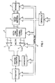
- a multi-mode radio transceiver shown in Fig. 1 there is a sequence of bi-directional circuit modules comprising a radio frequency head unit 1, a baseband converter 2, analogue/digital converters 3, a first digital signal processing stage 4, a second digital signal processing stage 5, and an interface 6.
- a frequency synthesiser 7 and a controller 8 which is linked to the modules via a control bus 9.
- reception signals are amplified (optionally) in the RF head unit and presented to the baseband converter.
- the baseband converter contains two mixers which have either their local oscillator signals or RF input signals at 90° relative phase shift.
- the resulting quadrature baseband signals are then applied to the analogue to digital converters (ADCs).
- ADCs analogue to digital converters
- the filtering may be minimal, merely protecting the RF circuitry from unwanted signals and preventing aliasing of frequencies by the ADCs.
- the digitised baseband signals are then passed to the DSPs which implement some or all of the following processes, as appropriate:
- the AGC can be used to modify the gain of the RF head unit and baseband converter and internally within the DSP to adjust the digital samples.
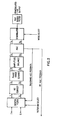
- the incoming I & Q quadrature channel signals are applied first to a digital filter 10.
- the filtered signals are then DC offset corrected (11), phase error corrected (12) and amplitude balanced (13).
- An automatic gain control (AGC) 14 is then applied before demodulation (15) is effected, e.g. in the manner disclosed in British patent application 8127797.
- the demodulated signals are passed through a post-demodulation filter 16.
- the AGC can be applied via feedback circuits, e.g. to either the digital filter 10 or possibly to the r.f. head unit 1.
- AGC can also be applied after the demodulation process, using a feed forward gain control loop. This is particularly useful when the AM demodulator according to BPA 8127797 is used. Since demodulation is a software controlled digital process the choice of demodulation mode is effected by means of a mode programme selection.
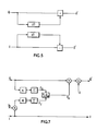
- corrections can be applied aerially or in nested loops.
- the filtered output from this detector can be directly applied as a correction signal, as shown.
- the zero crossings may be determined by zero-crossing detectors, or simple amplitude limiters may be used. In some cases it may be necessary to apply a weighting or scaling factor to the correction signal before it is used.
- the amplitude balance scheme of Figure 7 feeds an exact correction signal forward. The long term averages of rectified channel signals are divided to produce the correction factor. By halving the I-channel signal, the correction factor becomes approximately 1/2. Restricting the result of the E I/ E Q division to fractional positive numbers considerably simplifies the realisation of this loop by a digital signal processor.
- the channel imbalances need not be considered specifically as offset, phase and amplitude (or gain) terms but as any error set of the correct order.
- a long term correlation of the two channel signals will mathematically yield a correction signal of appropriate order.
- the interface provides a digital signal from which the DSPs generate baseband I- and Q-channels. These signals are converted into analogue form by the DACs.
- the mixers of the baseband converter move these signals to RF by local oscillators at 90° relative phase shift (or with 90° applied to one signal path). The addition of these two signals produces the required RF signal which is amplified (optionally) in the RF head unit.
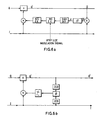
- the AM signal is converted to RF.
- the message signal is integrated to give phase values.
- the quadrature channel signals are found from sine and cosine look up tables.
- the signals are mixed with quadrature carrier signals and summed to produce the correct FM spectrum.
- phase modulation Figure 10
- the same steps as FM are required except that the digitised message signal is used directly as the phase value for the sine and cosine look up tables.
- SSB is generated by the Weaver method which is based on quadrature channel cancellations.
- Balance corrections may be derived from a receiving measurement to estimate the imbalance on transmission (assuming reciprocity) or by feedback or feedforward loops based on the baseband converter output.
Applications Claiming Priority (2)
| Application Number | Priority Date | Filing Date | Title |
|---|---|---|---|
| GB8426953 | 1984-10-25 | ||
| GB08426953A GB2166324A (en) | 1984-10-25 | 1984-10-25 | A multi-mode radio transceiver |
Publications (2)
| Publication Number | Publication Date |
|---|---|
| EP0180339A2 true EP0180339A2 (fr) | 1986-05-07 |
| EP0180339A3 EP0180339A3 (fr) | 1988-01-07 |
Family
ID=10568717
Family Applications (1)
| Application Number | Title | Priority Date | Filing Date |
|---|---|---|---|
| EP85307038A Withdrawn EP0180339A3 (fr) | 1984-10-25 | 1985-10-02 | Emetteur-récepteur radio multimode |
Country Status (4)
| Country | Link |
|---|---|
| EP (1) | EP0180339A3 (fr) |
| JP (1) | JPS61105948A (fr) |
| AU (1) | AU4839385A (fr) |
| GB (1) | GB2166324A (fr) |
Cited By (25)
| Publication number | Priority date | Publication date | Assignee | Title |
|---|---|---|---|---|
| EP0255175A2 (fr) * | 1986-08-01 | 1988-02-03 | Philips Electronics Uk Limited | Démodulation d'un signal modulé angulairement |
| EP0255553A1 (fr) * | 1986-08-07 | 1988-02-10 | Deutsche ITT Industries GmbH | Méthode pour la réception de signaux stéréo multiplex modulés en fréquence |
| EP0282607A1 (fr) * | 1987-03-14 | 1988-09-21 | Deutsche ITT Industries GmbH | Circuit de transposition en fréquence pour un signal de télévision |
| EP0285252A2 (fr) * | 1987-02-27 | 1988-10-05 | British Aerospace Public Limited Company | Démodulateur numérique |
| EP0333266A2 (fr) * | 1988-03-16 | 1989-09-20 | Philips Electronics Uk Limited | Récepteur à conversion directe |
| EP0335037A1 (fr) * | 1988-03-26 | 1989-10-04 | Stc Plc | Radio à conversion directe |
| EP0343273A1 (fr) * | 1988-05-27 | 1989-11-29 | Deutsche ITT Industries GmbH | Circuit de correction pour une paire de signaux numériques en quadrature |
| EP0349660A1 (fr) * | 1988-07-02 | 1990-01-10 | Deutsche ITT Industries GmbH | Circuit de conversion de fréquence pour un canal de télévision |
| DE3938643A1 (de) * | 1988-11-22 | 1990-05-23 | Ascom Radiocom Ag | Verfahren zum rekonstruieren verlorener dc-nutzanteile an zf-signalen in einem direct-conversion-empfaenger und empfaenger zum durchfuehren des verfahrens |
| DE3938671A1 (de) * | 1988-11-22 | 1990-05-23 | Ascom Radiocom Ag | Verfahren zum korrigieren von amplituden- und phasenfehlern in einem direct-conversion-empfaenger und empfaenger zum durchfuehren des verfahrens |
| EP0401771A2 (fr) * | 1989-06-09 | 1990-12-12 | TEMIC TELEFUNKEN microelectronic GmbH | Montage de circuit pour conversion en fréquence |
| FR2666709A1 (fr) * | 1990-08-24 | 1992-03-13 | Motorola Inc | Ensemble de reglage de gain pour radiotelephone. |
| EP0478265A1 (fr) * | 1990-09-25 | 1992-04-01 | Hewlett-Packard Company | Modulateur vectoriel basé sur la phase |
| EP0502546A2 (fr) * | 1991-03-06 | 1992-09-09 | Mitsubishi Denki Kabushiki Kaisha | Appareil de radiocommunication |
| DE4238543C1 (de) * | 1992-11-14 | 1994-05-05 | Hagenuk Telecom Gmbh | Verfahren und Vorrichtung zur Korrektur der Phasen- und Amplitudenfehler bei direktmischenden Empfangseinrichtungen |
| EP0801495A2 (fr) * | 1996-04-11 | 1997-10-15 | Sony Corporation | Appareil de transmission de données |
| WO1999001933A2 (fr) * | 1997-07-01 | 1999-01-14 | Telefonaktiebolaget Lm Ericsson (Publ) | Recepteur de conversion directe a mode multiple |
| EP1292017A1 (fr) * | 2001-09-08 | 2003-03-12 | Semiconductor Ideas to The Market BV | Récepteur en quadrature |
| EP1298791A1 (fr) * | 2001-09-26 | 2003-04-02 | Sony International (Europe) GmbH | Récepteur à conversion directe utilisant une correction d' erreurs d' orthogonalité |
| EP1363391A1 (fr) * | 2002-05-14 | 2003-11-19 | Ditrans Corporation | Récepteur en quadrature utilisant la compensation du décalage du composant continu , et la compensation d'erreurs de phase et amplitude |
| WO2004047411A1 (fr) | 2002-11-15 | 2004-06-03 | Interdigital Technology Corporation | Compensation de defaillances de composants radio par des specifications elargies |
| EP1480331A1 (fr) | 2003-05-20 | 2004-11-24 | Broadcom Corporation | Procédé de correction d' erreurs d' orthogonalité pour la réception de la télévision analogique en utiilisant des circuits d' accord à conversion directe |
| US6842489B2 (en) | 1999-06-03 | 2005-01-11 | Ditrans Ip, Inc. | Coherent adaptive calibration system and method |
| EP2267890A3 (fr) * | 2001-02-16 | 2012-08-01 | Qualcomm Incorporated | Architecture de récepteur de conversion directe |
| WO2014058752A3 (fr) * | 2012-10-08 | 2014-06-12 | Qualcomm Incorporated | Système et procédé pour la correction d'un déséquilibre iq |
Families Citing this family (5)
| Publication number | Priority date | Publication date | Assignee | Title |
|---|---|---|---|---|
| GB9001333D0 (en) * | 1990-01-19 | 1995-11-08 | Secr Defence | Circuit module for a phased array radar |
| CA2407943A1 (fr) | 2001-02-05 | 2002-08-15 | Clark Cohen | Systeme et procede peu onereux permettant d'effectuer des mesures dans les deux bandes de gps |
| GB2406984B (en) * | 2003-06-18 | 2005-12-21 | Motorola Inc | Method and arrangement for I-Q balancing and radio receiver incorporating same |
| JP4821379B2 (ja) * | 2006-03-09 | 2011-11-24 | オムロン株式会社 | 復調装置、距離測定装置、およびデータ受信装置 |
| JP4799303B2 (ja) * | 2006-07-13 | 2011-10-26 | 三菱電機エンジニアリング株式会社 | 変調器及び超指向性音響装置 |
Citations (4)
| Publication number | Priority date | Publication date | Assignee | Title |
|---|---|---|---|---|
| US3953805A (en) * | 1974-11-07 | 1976-04-27 | Texas Instruments Incorporated | DC component suppression in zero CF IF systems |
| US4159475A (en) * | 1978-06-05 | 1979-06-26 | Calspan Corporation | VCO-Controlled phase lock system |
| EP0048229A2 (fr) * | 1980-09-12 | 1982-03-24 | Telefonaktiebolaget L M Ericsson | Arrangement dans un système de radar pour la correction des erreurs de phase et d'amplitude en signal vidéo |
| EP0074858A2 (fr) * | 1981-09-15 | 1983-03-23 | International Standard Electric Corporation | Récepteur radio |
Family Cites Families (1)
| Publication number | Priority date | Publication date | Assignee | Title |
|---|---|---|---|---|
| GB1556087A (en) * | 1977-12-01 | 1979-11-21 | Standard Telephones Cables Ltd | Single channel duplex radio system |
-
1984
- 1984-10-25 GB GB08426953A patent/GB2166324A/en not_active Withdrawn
-
1985
- 1985-10-02 EP EP85307038A patent/EP0180339A3/fr not_active Withdrawn
- 1985-10-08 AU AU48393/85A patent/AU4839385A/en not_active Abandoned
- 1985-10-24 JP JP23855285A patent/JPS61105948A/ja active Pending
Patent Citations (4)
| Publication number | Priority date | Publication date | Assignee | Title |
|---|---|---|---|---|
| US3953805A (en) * | 1974-11-07 | 1976-04-27 | Texas Instruments Incorporated | DC component suppression in zero CF IF systems |
| US4159475A (en) * | 1978-06-05 | 1979-06-26 | Calspan Corporation | VCO-Controlled phase lock system |
| EP0048229A2 (fr) * | 1980-09-12 | 1982-03-24 | Telefonaktiebolaget L M Ericsson | Arrangement dans un système de radar pour la correction des erreurs de phase et d'amplitude en signal vidéo |
| EP0074858A2 (fr) * | 1981-09-15 | 1983-03-23 | International Standard Electric Corporation | Récepteur radio |
Non-Patent Citations (1)
| Title |
|---|
| INTERNATIONAL CONFERENCE, MOBILE RADIO SYSTEMS AND TECHNIQUES, York, 10th-13th September 1984, pages 6-10, Hitchin, GB; J. MASTERTON et al.: "Digital techniques for advanced radio" * |
Cited By (62)
| Publication number | Priority date | Publication date | Assignee | Title |
|---|---|---|---|---|
| EP0255175A3 (fr) * | 1986-08-01 | 1989-03-15 | Philips Electronics Uk Limited | Démodulation d'un signal modulé angulairement |
| EP0255175A2 (fr) * | 1986-08-01 | 1988-02-03 | Philips Electronics Uk Limited | Démodulation d'un signal modulé angulairement |
| EP0255553A1 (fr) * | 1986-08-07 | 1988-02-10 | Deutsche ITT Industries GmbH | Méthode pour la réception de signaux stéréo multiplex modulés en fréquence |
| US4817167A (en) * | 1986-08-07 | 1989-03-28 | Deutsche Itt Industries Gmbh | Method of receiving frequency-modulated stereo multiplex signals |
| EP0285252A2 (fr) * | 1987-02-27 | 1988-10-05 | British Aerospace Public Limited Company | Démodulateur numérique |
| EP0285252A3 (fr) * | 1987-02-27 | 1989-08-02 | British Aerospace Public Limited Company | Démodulateur numérique |
| US4789897A (en) * | 1987-03-14 | 1988-12-06 | Deutsche Itt Industries Gmbh | Frequency converting apparatus for converting an RF television signal to a video signal employing low IF techniques |
| EP0282607A1 (fr) * | 1987-03-14 | 1988-09-21 | Deutsche ITT Industries GmbH | Circuit de transposition en fréquence pour un signal de télévision |
| EP0333266A2 (fr) * | 1988-03-16 | 1989-09-20 | Philips Electronics Uk Limited | Récepteur à conversion directe |
| EP0333266A3 (en) * | 1988-03-16 | 1990-03-21 | Philips Electronic And Associated Industries Limited | A direct conversion receiver |
| EP0335037A1 (fr) * | 1988-03-26 | 1989-10-04 | Stc Plc | Radio à conversion directe |
| EP0343273A1 (fr) * | 1988-05-27 | 1989-11-29 | Deutsche ITT Industries GmbH | Circuit de correction pour une paire de signaux numériques en quadrature |
| US4926443A (en) * | 1988-05-27 | 1990-05-15 | Deutsche Itt Industries Gmbh | Correction circuit for a digital quadrature-signal pair |
| US4974086A (en) * | 1988-07-02 | 1990-11-27 | Deutsche Itt Industries Gmbh | Frequency conversion circuit for a color television channel |
| EP0349660A1 (fr) * | 1988-07-02 | 1990-01-10 | Deutsche ITT Industries GmbH | Circuit de conversion de fréquence pour un canal de télévision |
| DE3938643A1 (de) * | 1988-11-22 | 1990-05-23 | Ascom Radiocom Ag | Verfahren zum rekonstruieren verlorener dc-nutzanteile an zf-signalen in einem direct-conversion-empfaenger und empfaenger zum durchfuehren des verfahrens |
| DE3938643C2 (de) * | 1988-11-22 | 1999-03-25 | Motorola Inc | Verfahren zum Rekonstruieren abgetrennter Gleichspannungsnutzanteile an ZF-Signalen in einem Direct-Conversion-Empfänger und Empfänger zum Durchführen des Verfahrens |
| DE3938671C2 (de) * | 1988-11-22 | 1999-02-25 | Motorola Inc | Verfahren zum Korrigieren von Amplituden- und Phasenfehlern in einem Direct-Conversion-Empfänger und Empfänger zum Durchführen des Verfahrens |
| DE3938671A1 (de) * | 1988-11-22 | 1990-05-23 | Ascom Radiocom Ag | Verfahren zum korrigieren von amplituden- und phasenfehlern in einem direct-conversion-empfaenger und empfaenger zum durchfuehren des verfahrens |
| EP0401771A2 (fr) * | 1989-06-09 | 1990-12-12 | TEMIC TELEFUNKEN microelectronic GmbH | Montage de circuit pour conversion en fréquence |
| EP0401771A3 (fr) * | 1989-06-09 | 1991-09-04 | TEMIC TELEFUNKEN microelectronic GmbH | Montage de circuit pour conversion en fréquence |
| US5179731A (en) * | 1989-06-09 | 1993-01-12 | Licentia-Patent-Verwaltungs-Gmbh | Frequency conversion circuit |
| FR2666709A1 (fr) * | 1990-08-24 | 1992-03-13 | Motorola Inc | Ensemble de reglage de gain pour radiotelephone. |
| EP0478265A1 (fr) * | 1990-09-25 | 1992-04-01 | Hewlett-Packard Company | Modulateur vectoriel basé sur la phase |
| EP0502546A3 (en) * | 1991-03-06 | 1992-12-23 | Mitsubishi Denki Kabushiki Kaisha | Radio communication apparatus |
| AU643848B2 (en) * | 1991-03-06 | 1993-11-25 | Mitsubishi Denki Kabushiki Kaisha | Radio communication apparatus |
| EP0502546A2 (fr) * | 1991-03-06 | 1992-09-09 | Mitsubishi Denki Kabushiki Kaisha | Appareil de radiocommunication |
| DE4238543C1 (de) * | 1992-11-14 | 1994-05-05 | Hagenuk Telecom Gmbh | Verfahren und Vorrichtung zur Korrektur der Phasen- und Amplitudenfehler bei direktmischenden Empfangseinrichtungen |
| EP0602394A2 (fr) * | 1992-11-14 | 1994-06-22 | Hagenuk Telecom GmbH | Procédé et dispositif de correction des erreurs de phase et d'amplitude pour des dispositifs récepteurs à conversion directe |
| EP0602394A3 (fr) * | 1992-11-14 | 1995-02-08 | Hagenuk Telecom Gmbh | Procédé et dispositif de correction des erreurs de phase et d'amplitude pour des dispositifs récepteurs à conversion directe. |
| EP0801495A3 (fr) * | 1996-04-11 | 1999-03-03 | Sony Corporation | Appareil de transmission de données |
| EP0801495A2 (fr) * | 1996-04-11 | 1997-10-15 | Sony Corporation | Appareil de transmission de données |
| US5963597A (en) * | 1996-04-11 | 1999-10-05 | Sony Corporation | Data transmission apparatus |
| WO1999001933A3 (fr) * | 1997-07-01 | 1999-04-01 | Ericsson Telefon Ab L M | Recepteur de conversion directe a mode multiple |
| US6029052A (en) * | 1997-07-01 | 2000-02-22 | Telefonaktiebolaget Lm Ericsson | Multiple-mode direct conversion receiver |
| AU745063B2 (en) * | 1997-07-01 | 2002-03-07 | Telefonaktiebolaget Lm Ericsson (Publ) | Multiple mode direct conversion receiver |
| WO1999001933A2 (fr) * | 1997-07-01 | 1999-01-14 | Telefonaktiebolaget Lm Ericsson (Publ) | Recepteur de conversion directe a mode multiple |
| US6842489B2 (en) | 1999-06-03 | 2005-01-11 | Ditrans Ip, Inc. | Coherent adaptive calibration system and method |
| US8626099B2 (en) | 2001-02-16 | 2014-01-07 | Qualcomm Incorporated | Direct conversion receiver architecture |
| US8634790B2 (en) | 2001-02-16 | 2014-01-21 | Qualcomm Incorporated | Direct conversion receiver architecture with digital fine resolution variable gain amplification |
| EP2267890A3 (fr) * | 2001-02-16 | 2012-08-01 | Qualcomm Incorporated | Architecture de récepteur de conversion directe |
| US8615212B2 (en) | 2001-02-16 | 2013-12-24 | Qualcomm Incorporated | Direct conversion receiver architecture |
| EP2273674A3 (fr) * | 2001-02-16 | 2012-08-08 | Qualcomm Incorporated | Architecture de récepteur de conversion directe |
| EP2267888A3 (fr) * | 2001-02-16 | 2012-08-08 | Qualcomm Incorporated | Architecture de récepteur de conversion directe |
| EP2267887A3 (fr) * | 2001-02-16 | 2012-08-01 | Qualcomm Incorporated | Architecture de récepteur de conversion directe |
| WO2003023950A3 (fr) * | 2001-09-08 | 2004-03-11 | Semiconductor Ideas Market Bv | Recepteur |
| WO2003023950A2 (fr) * | 2001-09-08 | 2003-03-20 | Semiconductor Ideas To The Market (Itom) B.V. | Recepteur |
| EP1292017A1 (fr) * | 2001-09-08 | 2003-03-12 | Semiconductor Ideas to The Market BV | Récepteur en quadrature |
| EP1298791A1 (fr) * | 2001-09-26 | 2003-04-02 | Sony International (Europe) GmbH | Récepteur à conversion directe utilisant une correction d' erreurs d' orthogonalité |
| EP1363391A1 (fr) * | 2002-05-14 | 2003-11-19 | Ditrans Corporation | Récepteur en quadrature utilisant la compensation du décalage du composant continu , et la compensation d'erreurs de phase et amplitude |
| EP1568192A1 (fr) * | 2002-11-15 | 2005-08-31 | Interdigital Technology Corporation | Compensation de defaillances de composants radio par des specifications elargies |
| KR100979154B1 (ko) | 2002-11-15 | 2010-08-31 | 인터디지탈 테크날러지 코포레이션 | 사양을 완화하기 위한 아날로그 무선 컴포넌트 손상의 보상 |
| KR100960065B1 (ko) | 2002-11-15 | 2010-05-31 | 인터디지탈 테크날러지 코포레이션 | 사양을 완화하기 위한 아날로그 무선 컴포넌트 손상의 보상 |
| CN1781298B (zh) * | 2002-11-15 | 2010-04-07 | 美商内数位科技公司 | 用于射频参数需求的无线传输/接收单元与方法 |
| US7257379B2 (en) | 2002-11-15 | 2007-08-14 | Interdigital Technology Corporation | Compensating for analog radio component impairments to relax specifications |
| EP1568192A4 (fr) * | 2002-11-15 | 2006-08-23 | Interdigital Tech Corp | Compensation de defaillances de composants radio par des specifications elargies |
| WO2004047411A1 (fr) | 2002-11-15 | 2004-06-03 | Interdigital Technology Corporation | Compensation de defaillances de composants radio par des specifications elargies |
| US8165554B2 (en) | 2003-05-20 | 2012-04-24 | Gomez Ramon A | Quadrature correction method for analog television reception using direct-conversion tuners |
| US7412222B2 (en) | 2003-05-20 | 2008-08-12 | Broadcom Corporation | Quadrature correction method for analog television reception using direct-conversion tuners |
| EP1480331A1 (fr) | 2003-05-20 | 2004-11-24 | Broadcom Corporation | Procédé de correction d' erreurs d' orthogonalité pour la réception de la télévision analogique en utiilisant des circuits d' accord à conversion directe |
| WO2014058752A3 (fr) * | 2012-10-08 | 2014-06-12 | Qualcomm Incorporated | Système et procédé pour la correction d'un déséquilibre iq |
| US9094079B2 (en) | 2012-10-08 | 2015-07-28 | Qualcomm Incorporated | System and method for I-Q imbalance correction |
Also Published As
| Publication number | Publication date |
|---|---|
| GB2166324A (en) | 1986-04-30 |
| JPS61105948A (ja) | 1986-05-24 |
| GB8426953D0 (en) | 1984-11-28 |
| AU4839385A (en) | 1986-05-01 |
| EP0180339A3 (fr) | 1988-01-07 |
Similar Documents
| Publication | Publication Date | Title |
|---|---|---|
| EP0180339A2 (fr) | Emetteur-récepteur radio multimode | |
| US4731796A (en) | Multi-mode radio transceiver | |
| US7881401B2 (en) | Transmitter arrangement and signal processing method | |
| EP0729230B1 (fr) | Récepteur à fréquence intermédiaire zéro | |
| US7787630B2 (en) | FM stereo decoder incorporating Costas loop pilot to stereo component phase correction | |
| EP0639306B1 (fr) | Procede et appareil d'amplification, de modulation et de demodulation | |
| US4653117A (en) | Dual conversion FM receiver using phase locked direct conversion IF | |
| US5878089A (en) | Coherent signal detector for AM-compatible digital audio broadcast waveform recovery | |
| JPS6412128B2 (fr) | ||
| US7492838B2 (en) | Apparatus for compensating for phase mismatch in QPSK demodulator | |
| US20060160519A1 (en) | Direct-conversion receiver system and method, especially a GPS receiver system with high pass filtering | |
| US6442383B1 (en) | Demodulator and digital wireless communication receiver | |
| US4750214A (en) | Digital FM demodulator using delayed signal product with arctangent | |
| CA2054173A1 (fr) | Recepteur radio numerique a limiteur d'amplitude et a detecteur logarithmique | |
| US20090117870A1 (en) | Receiver | |
| JPH0628338B2 (ja) | フエーズロツクドループ及びそれを用いる直接混合同期am受信機 | |
| EP0807344B1 (fr) | Procédé et appareil pour générer plusieurs porteuses modulées en quadrature | |
| KR19990072574A (ko) | 디지털mpx신호복조기용반송파발생장치 | |
| JP3386114B2 (ja) | 復調装置及び方法 | |
| GB2213006A (en) | Zero-IF transmitter with error correction | |
| JP2004040678A (ja) | 復調装置 | |
| US4324952A (en) | Direct function receivers and transmitters for multichannel communications system | |
| AU8307691A (en) | Dual mode automatic gain control | |
| JPH09238171A (ja) | 直交位相成分を含む変調信号の復調回路 | |
| JP2004193724A (ja) | ダイレクトコンバージョン受信機 |
Legal Events
| Date | Code | Title | Description |
|---|---|---|---|
| PUAI | Public reference made under article 153(3) epc to a published international application that has entered the european phase |
Free format text: ORIGINAL CODE: 0009012 |
|
| AK | Designated contracting states |
Kind code of ref document: A2 Designated state(s): AT BE CH DE FR IT LI LU NL SE |
|
| RAP1 | Party data changed (applicant data changed or rights of an application transferred) |
Owner name: STC PLC |
|
| PUAL | Search report despatched |
Free format text: ORIGINAL CODE: 0009013 |
|
| AK | Designated contracting states |
Kind code of ref document: A3 Designated state(s): AT BE CH DE FR IT LI LU NL SE |
|
| STAA | Information on the status of an ep patent application or granted ep patent |
Free format text: STATUS: THE APPLICATION IS DEEMED TO BE WITHDRAWN |
|
| 18D | Application deemed to be withdrawn |
Effective date: 19880708 |
|
| RIN1 | Information on inventor provided before grant (corrected) |
Inventor name: RAMSDALE, PETER ALAN Inventor name: MASTERTON, JOHN |