EP0183347B1 - Video image recognition system - Google Patents
Video image recognition system Download PDFInfo
- Publication number
- EP0183347B1 EP0183347B1 EP85306610A EP85306610A EP0183347B1 EP 0183347 B1 EP0183347 B1 EP 0183347B1 EP 85306610 A EP85306610 A EP 85306610A EP 85306610 A EP85306610 A EP 85306610A EP 0183347 B1 EP0183347 B1 EP 0183347B1
- Authority
- EP
- European Patent Office
- Prior art keywords
- region
- image
- features
- matching
- offsets
- Prior art date
- Legal status (The legal status is an assumption and is not a legal conclusion. Google has not performed a legal analysis and makes no representation as to the accuracy of the status listed.)
- Expired
Links
Images


Classifications
-
- G—PHYSICS
- G06—COMPUTING; CALCULATING OR COUNTING
- G06V—IMAGE OR VIDEO RECOGNITION OR UNDERSTANDING
- G06V30/00—Character recognition; Recognising digital ink; Document-oriented image-based pattern recognition
- G06V30/10—Character recognition
- G06V30/24—Character recognition characterised by the processing or recognition method
- G06V30/248—Character recognition characterised by the processing or recognition method involving plural approaches, e.g. verification by template match; Resolving confusion among similar patterns, e.g. "O" versus "Q"
- G06V30/2504—Coarse or fine approaches, e.g. resolution of ambiguities or multiscale approaches
Definitions
- This invention relates to an object recognition system and, more particularly, to an apparatus and a method for screening an image for reference patterns and selecting the reference pattern which most closely matches the image.
- Object or pattern recognition is finding wide applications in industry.
- the two main techniques utilized for object classification or recognition are template matching and recognition by features.
- template matching the objective is to find the best embedding of a template subimage in an observed image, over transformations such as translation.
- one approach is to store a dense set of possible views (or other image descriptors) so that any sensed image is "sufficiently close" to one member of the dense set of views.
- This approach has at least two problems for many real applications. First, cardinality of the set of views becomes too large for storage and efficient retrieval. Secondly, template matching (particularly matching of an entire image) is very time consuming for a large template library unless it is done in special purpose hardware.
- the video image (or any two dimensional data) is segmented into two or more regions, the curvature and orientation attributes of selected local features of each region are determined and screened against the respective attributes of reference patterns stored in an attribute memory and the reference patterns are identified and retrieved from memory.
- a horizontal and a vertical offset is computed from individual horizontal and vertical offsets for each of the selected local features of the region generated by matching each of the selected local features with the corresponding one of the reference features.
- the closest reference pattern for each region of the video image is determined by aligning each region against the reference patterns using the so computed offsets and matching the intensity thereof.
- the present invention selects a group of reference images using feature attribute matching for fast coarse searching and selects the best reference image from the group using intensity or template matching for fine matching. This approach keeps the accuracy of recognition high without resorting to the time consuming exhaustive search by template matching.
- the disclosed image recognition system can also be used as a content based retrieval system.
- Fig. 1 Shown in Fig. 1 is a function block diagram or architecture of the present invention.
- the present object recognition system includes a training mode and a recognition mode.
- video disc 101 contains images of objects to be identified during the recognition mode.
- Each disc frame stores one view of an object (template).
- object identification, position, orientation, view angle and distance with respect to the camera This information may be encoded in the frame, or stored in a separate memory.
- One object may be stored in many views representing varying orientations and distances.
- an image received from an input device is stored in the frame buffer 102, then parts of that image that may represent objects, or regions, are extracted by a region isolator 103 and sent to a feature analyzer 104.
- Feature analyzer 104 computes a set of global and local features for each region and based on those features selects several reference patterns from an associated attribute memory 106, whose features most closely match those of the region.
- the region is then compared against the selected reference patterns by iconic matcher 105 using two-dimensional correlation, or template matching, to establish a degree of correspondence to each of the reference patterns.
- This architecture combines the two main approaches to object recognition: recognition by features and template matching.
- the present invention uses feature based recognition to quickly select all the reference patterns which coarsely resemble the image and then uses the slower template matching technique to accurately select which of the selected reference images most closely matches the image.
- Fig. 2 illustrates one hardware implementation of an object recognition system in accordance with the present invention. It comprises a video disc 101 and disc controller unit 201, camera 203, a frame buffer 102 with image analog to digital A/ D converter, or digitizer, 202, Motorola MC 68000 processor 204 is used as the system controller with program memory 205 including attribute memory 106, and a high speed image processor 206.
- the image digitizer, frame buffer and image processor are connected by a high speed bus 207 for communicating digitized images and they are connected with system controller 204 via Multi- bus 208. While the disclosed embodiment utilizes a video disc, obviously other types of large capacity memories can be utilized. It should be noted that the object recognition time of the system is highly dependent on the access time of the disc or other memory utilized.
- Frame buffer 203 can store 1 frame of 521 x 512 or 4 frames of 256 x 256 8 bits pixels (picture elements) and it has built in pan and scroll operations (horizontal and vertical shifts).
- Image processor 206 to implement the algorithm of Fig. 9 may include a fast ALU (Arithmetic Logic Unit), 5 adders, 3 multipliers, a static memory for storing two images, all controlled by a programmable sequencer. Segmentation, matching and the calculation of global features is done in image processor 206, while analysis of features, initial template selection and the system control is implemented in processor 204. Thus, image processor 206 performs the region isolator 103 and iconic matcher 105 functions shown in Fig. 1, while processor 204 performs the feature analyzer 104 function shown in Fig. 1.
- ALU Arimetic Logic Unit
- the first integer of a referenced item denotes the drawing figure in which the referenced item is illustrated (e.g., 801 is found in Fig. 8).
- the training mode of the system is described.
- the training mode is typically entered when a new disc is placed in service.
- the disc contains many views or patterns representing varying orientations and distance of the objects to be recognized by the system.
- step 301 a reference frame of the disc is read into frame buffer 102.
- the region isolator 103 is activated, 302, and extracts the template (the part of the frame containing the object) from the frame. Note, during the training mode there is only one template or pattern on each image reference frame of the disc. The detailed operation of region isolator 103 will be described in Fig. 5. Region isolator 103 presents the information extracted from this template to the feature analyzer 303. Feature analyzer 303 also receives the disc address of this frame.
- Feature analyzer 104 computes the global and local features or attributes for the template or pattern and stores them in a list in attribute memory 106 as shown in 801 of Fig. 8, along with the address of the disc frame containing the template. The detailed operation of feature analyzer 104 will be described in Fig. 6.
- step 304 if there are more image reference frames on the disc 101 they are also processed as shown in steps 301, 302 and 303. After the last image reference frame is completed a "build classifer" command is sent to feature analyzer 104 and the operation is completed 306.
- feature analyzer 104 constructs a classification tree using the attribute data, to enable a fast logic access to frames containing similar patterns during the recognition mode. This classification tree includes address information associated with the attribute data for locating matching images on frames on the disc using the attribute data.
- the recognition mode of the system is described.
- an image from the camera or similar device is read, during step 401, into frame buffer 102.
- the region isolator is activated and the image is segmented into regions, each region contains a prominent object which is to be analyzed by the feature analyzer 104.
- the feature analyzer 104 and iconic matcher 105 are activated.
- the list of recognized objects is set to "empty". An element of this list corresponds to a recognized object. It contains disc address of a frame containing the matching template, and X, Y offsets specifying the position in the image from the camera where the match is found.
- step 405 the system controller checks if there is any data to be read from feature Analyzer 104. If there is, it reads one portion containing disc address and X, Y offsets at a recognized template 406.
- step 407 a check is made for an element of the list S having the same disc address and X, Y offsets as the last read values. If there is one, the last values are not used, and the control returns to step 405 to check if there is more data to be read from feature Analyzer 104. If there is no such element in S, a new element is created, containing last read values of disc address and X, Y offsets, and added to S, step 408, and the control returns to step 405 to check for more data from feature Analyzer 104.
- step 409 When the test in step 405 shows that there is not more data from the feature Analyzer 104, a check is made, 409, if the list S is empty, which signifies that feature Analyzer 104 did not send any data at all. In this case a message "unrecognized image" is generated, step 411, if S is not empty. For each of its elements a message is generated, step 410, containing the X, Y offsets and the information associated with disc address, which may contain an object identification, or name, its distance from the position, orientation, view angle, disc address. The specific structure of this information will vary with applications. The process stops in step 412. All the messages generated by the system controller, Fig. 4, are sent either to user devices, or to the user portion of the software which may share the processor with this system.
- Region isolator 103 analyzes the images seen by camera 203 via frame buffer 102, step 501, and segments this image, step 502. Region isolator may segment using one of a variety of techniques including difference thresholding, image thresholding or edge following, depending on application requirements. These well known techniques are described in the book written by D. H. Ballard and C. M. Brown, entitled “Computer Vision", Prentice-Hall, Englewood Cliffs, 1982.
- the connected areas where the image intensity is greater (or smaller) than a threshold are extracted as regions.
- the threshold can be preset; computed from the intensity histogram or updated adaptively based on local intensities.
- the above tracing procedure terminates when the edge pixels completely enclose an area, or if the accumulated edge strength falls below a given value. If the extracted boundary completely encloses a region, this region is extracted, otherwise, a rectangular region surrounding the discovered portion of the boundary is extracted.
- step 506 bounding rectangle information is sent to iconic matcher 105 and the list of boundary points are sent to feature analyzer 104.
- step 508 system controller 204 returns control to the program that called region isolator 103, that is to either training program, Fig. 3 at step 303, or to recognition program, Fig. 4 at step 403.
- the operation of the feature analyzer 104 is described.
- the feature analyzer is invoked by either the training program, Fig. 3 at step 303, or by the recognition program, Fig. 4 at step 403.
- Feature analyzer 104 is an object recognition system in itself, fast but not very accurate. It is utilized in the present invention to reduce the search time by quickly identifying disc frames which coarsely resemble the object to be recognized. Feature analyzer 104 selects disc frames which are likely to match the isolated region by comparing the features calculated from the region of those of the images stored on video disc. Features are properties of regions which are simple to compute but they usually do not represent complete information about the object.
- the feature analyzer determines if a build classifier message (step 305 of Fig. 3) was received during the training mode. If so a hierarchical classification tree may be constructed, step 602, as described in the article by E. M.
- step 605 determines whether data was available from the region isolator. If no data was available from the region isolator, the test at step 605 directs the control to step 603 which returns it to the system controller.
- global and local features are determined.
- Global features include horizontal size, vertical size, area and variance of intensity within the region.
- Local features include maxima and minima of estimated boundary curvature, their values, orientations and positions. The local curvature may be estimated by the angle formed between two chords drawn on the boundary curves.
- Each global or local feature is represented by its type and a scalar or vector value.
- step 608 If the system is in the training program, step 608, then in step 607 these features are stored in locations (801) of the attribute memory (106) of the feature analyzer 104 along with the disc address of the frame received from the system controller, step 303.
- These attribute memory locations 801 contain a list of all templates stored on video disc 101. The description of each template consists of its frame address, and a list of features. The features on the list are ordered according to type and (for local features) their values.
- the information from the attribute memory is used to construct a hierarchical classification tree, step 602, when the system controller sends the message, "build classifier", after all the frames have been processed, step 305.
- the features of each extracted region are compared with the features of all templates of memory locations 801.
- the number of feature matches for each template is computed and n templates with highest number of feature matches are selected in step 609 for further matching.
- the previously referenced hierarchical classification technique may be used to improve the speed.
- the selected templates are matched with the region, one at a time, by the iconic matcher, steps 610, 611, 612, 614, 615 and 616.
- step 611 the x and y offsets between the region and each selected template needed to align them are computed by taking the median value of offsets generated by matching pairs of local features.
- the addresses of templates selected by the feature analyzer are sent, step 611, to the disc controller 201 so they can be retrieved from video disc 101 and sent to iconic matcher 105. Templates are ordered according to the number of matching features. At the same time the x and y offsets for each selected template are sent to iconic matcher, for the alignment of positions.
- the iconic matcher 105 provides accurate identification for undistorted and untransformed images. Consequently, the system should be able to positively identify an object as long as a template or frame corresponding to its particular view is stored on the video disc.
- step 701 the bounding rectangle which defines the segmented region is read from region isolator 103 (from step 506 of Fig. 5).
- step 702 the x and y offsets are obtained from feature analyzer 104 (from step 611 of Fig. 6).
- step 703 each template received from the video disc is aligned with the isolated segment or region according to the x and y offsets received from the feature analyzer in step 102.
- step 704 the value of R(IJ) is computed over the bounding rectangle of the template.
- the iconic matcher computes the normalized correlation between the isolated segmented region and templates retrieved from video disc 101. Normalized correlation between two images I (x, y) and J (x, y) is shown by 901 of Fig. 9. To compute R(IJ) the equivalent expression 902 of Fig. 9 may be easier implemented in hardware.
- the normalized correlation R(IJ) represents the degree to which a template corresponds to a segmented or isolated region of the image, the larger is its value, the better is the correspondence.
- the value R(IJ) range is between -1 and 1, and it is not affected by linear change (offset and gain) of intensity in either of the images.
- step 705 the normalized correlation R is returned to the feature analyzer.
- step 706 if additional offsets are received from the feature analyzer, step 702 is repeated; if not, the function of the iconic matcher is completed in step 707.
- the iconic matcher operates interactively with the feature analyzer (Fig. 6). Specifically, the steps 702-705 are executed between the steps 611 and 612 of the feature analyzer.
- the feature analyzer reads the match value R sent by iconic matcher, step 705.
- the value of R received from the iconic matcher is compared against a threshold. Note, the first template which R exceeds the fixed threshold may be taken as the recognized object and further matching may be aborted.
- the frame address and positional information will be retrieved and returned in step 613 to the system controller for outputting as the system's response. However, in some applications, it may be better to match all the chosen templates from the video disc and choose the template that shows the most correlation as the recognized object.
- the feature analyzer returns to step 604 to read the next set of boundary points, if any, defining the next region or segment of the image.
- step 615 the next template i + 1 is selected, steps 615, 616, if all n closest templates have not been checked. If all of the n templates have been checked, step 616, the next set of boundary points from the region isolator is read, step 604, and the process repeats. After all the available sets of boundary points have been processed, step 605, the control is returned in step 603 to the system controller.
- the above process finds templates which correspond totally to the segmented region but, it will be unable to detect a match when a part of the object image is missing (occlusion) or distorted.
- an occluded image matching algorithm which can be used to find a correspondence (match) between a template (reference image) and partially occluded or distorted image of the same object.
Description
- This invention relates to an object recognition system and, more particularly, to an apparatus and a method for screening an image for reference patterns and selecting the reference pattern which most closely matches the image.
- Object or pattern recognition is finding wide applications in industry. The two main techniques utilized for object classification or recognition are template matching and recognition by features. In template matching, the objective is to find the best embedding of a template subimage in an observed image, over transformations such as translation. In practice, one approach is to store a dense set of possible views (or other image descriptors) so that any sensed image is "sufficiently close" to one member of the dense set of views. This approach has at least two problems for many real applications. First, cardinality of the set of views becomes too large for storage and efficient retrieval. Secondly, template matching (particularly matching of an entire image) is very time consuming for a large template library unless it is done in special purpose hardware.
- A recognition system using template matching as set out in the preamble of
claims 1 and 8 is disclosed in US Patent 4,410,916 issued October 18, 1983 to Pratt et al. In this system certain statistical features are used to eliminate unworthy templates from consideration, and thus reduce the field of search. - According to the present invention there is provided a method and system as set out in the claims.
- More particularly, the video image (or any two dimensional data) is segmented into two or more regions, the curvature and orientation attributes of selected local features of each region are determined and screened against the respective attributes of reference patterns stored in an attribute memory and the reference patterns are identified and retrieved from memory. For each of the reference patterns, a horizontal and a vertical offset is computed from individual horizontal and vertical offsets for each of the selected local features of the region generated by matching each of the selected local features with the corresponding one of the reference features. The closest reference pattern for each region of the video image is determined by aligning each region against the reference patterns using the so computed offsets and matching the intensity thereof. Thus, the present invention selects a group of reference images using feature attribute matching for fast coarse searching and selects the best reference image from the group using intensity or template matching for fine matching. This approach keeps the accuracy of recognition high without resorting to the time consuming exhaustive search by template matching. The disclosed image recognition system can also be used as a content based retrieval system.
- The detailed description of the invention will be more fully appreciated from the illustrative embodiment shown in the drawing, in which:
- Fig. 1 is a functional block diagram of an object recognition system utilizing the present invention;
- Fig. 2 is a hardware implementation of the object recognition system;
- Fig. 3 shows a flow chart which describes the system controller training mode operating sequence;
- Fig. 4 shows a flow chart which describes the system controller recognition mode operating sequence;
- Fig. 5 shows a flow chart which describes the operation of the region isolator;
- Fig. 6 shows a flow chart which describes the operation of the feature analyzer;
- Fig. 7 shows a flow chart which describes the operation of the iconic matcher;
- Fig. 8 shows the attribute memory locations used by the present invention, and
- Fig. 9 shows normal correlation expressions which may be used by the iconic matcher.
- Shown in Fig. 1 is a function block diagram or architecture of the present invention. Generally, the present object recognition system includes a training mode and a recognition mode. At the beginning of the training mode,
video disc 101 contains images of objects to be identified during the recognition mode. Each disc frame stores one view of an object (template). There is additional information associated with each frame, or its disc address, which may contain object identification, position, orientation, view angle and distance with respect to the camera. This information may be encoded in the frame, or stored in a separate memory. One object may be stored in many views representing varying orientations and distances. The range of orientations, and distances as well as their resolutions depend on the application requirements (e.g., if a given piece part to be recognized is always presented in a specific orientation ±20 degrees, then only this range of angles would be stored). All the views of one object are stored in successive frames of the disc to make the selection process easier. - During the recognition mode an image received from an input device (e.g., camera) is stored in the
frame buffer 102, then parts of that image that may represent objects, or regions, are extracted by aregion isolator 103 and sent to afeature analyzer 104.Feature analyzer 104 computes a set of global and local features for each region and based on those features selects several reference patterns from an associatedattribute memory 106, whose features most closely match those of the region. The region is then compared against the selected reference patterns byiconic matcher 105 using two-dimensional correlation, or template matching, to establish a degree of correspondence to each of the reference patterns. This architecture combines the two main approaches to object recognition: recognition by features and template matching. The present invention uses feature based recognition to quickly select all the reference patterns which coarsely resemble the image and then uses the slower template matching technique to accurately select which of the selected reference images most closely matches the image. - Fig. 2 illustrates one hardware implementation of an object recognition system in accordance with the present invention. It comprises a
video disc 101 anddisc controller unit 201,camera 203, aframe buffer 102 with image analog to digital A/ D converter, or digitizer, 202, Motorola MC 68000processor 204 is used as the system controller withprogram memory 205 includingattribute memory 106, and a highspeed image processor 206. The image digitizer, frame buffer and image processor are connected by ahigh speed bus 207 for communicating digitized images and they are connected withsystem controller 204 via Multi- bus 208. While the disclosed embodiment utilizes a video disc, obviously other types of large capacity memories can be utilized. It should be noted that the object recognition time of the system is highly dependent on the access time of the disc or other memory utilized. -
Frame buffer 203 can store 1 frame of 521 x 512 or 4 frames of 256 x 256 8 bits pixels (picture elements) and it has built in pan and scroll operations (horizontal and vertical shifts). -
Image processor 206 to implement the algorithm of Fig. 9 may include a fast ALU (Arithmetic Logic Unit), 5 adders, 3 multipliers, a static memory for storing two images, all controlled by a programmable sequencer. Segmentation, matching and the calculation of global features is done inimage processor 206, while analysis of features, initial template selection and the system control is implemented inprocessor 204. Thus,image processor 206 performs theregion isolator 103 andiconic matcher 105 functions shown in Fig. 1, whileprocessor 204 performs thefeature analyzer 104 function shown in Fig. 1. - Note, in the following descriptions, the first integer of a referenced item denotes the drawing figure in which the referenced item is illustrated (e.g., 801 is found in Fig. 8).
- With reference to Figs. 1, 3 and 6, the training mode of the system is described. The training mode is typically entered when a new disc is placed in service. The disc contains many views or patterns representing varying orientations and distance of the objects to be recognized by the system.
- In step 301 a reference frame of the disc is read into
frame buffer 102. Theregion isolator 103 is activated, 302, and extracts the template (the part of the frame containing the object) from the frame. Note, during the training mode there is only one template or pattern on each image reference frame of the disc. The detailed operation ofregion isolator 103 will be described in Fig. 5.Region isolator 103 presents the information extracted from this template to thefeature analyzer 303.Feature analyzer 303 also receives the disc address of this frame. -
Feature analyzer 104 computes the global and local features or attributes for the template or pattern and stores them in a list inattribute memory 106 as shown in 801 of Fig. 8, along with the address of the disc frame containing the template. The detailed operation offeature analyzer 104 will be described in Fig. 6. Instep 304, if there are more image reference frames on thedisc 101 they are also processed as shown insteps analyzer 104 and the operation is completed 306. In response thereto featureanalyzer 104, as will be discussed in Fig. 6, constructs a classification tree using the attribute data, to enable a fast logic access to frames containing similar patterns during the recognition mode. This classification tree includes address information associated with the attribute data for locating matching images on frames on the disc using the attribute data. - With reference to Figs. 1, 2, 4 and 6 the recognition mode of the system is described. In the recognition mode an image from the camera or similar device is read, during
step 401, intoframe buffer 102. Instep 402 the region isolator is activated and the image is segmented into regions, each region contains a prominent object which is to be analyzed by thefeature analyzer 104. Instep 403 thefeature analyzer 104 andiconic matcher 105 are activated. Instep 404, the list of recognized objects is set to "empty". An element of this list corresponds to a recognized object. It contains disc address of a frame containing the matching template, and X, Y offsets specifying the position in the image from the camera where the match is found. Instep 405 the system controller checks if there is any data to be read fromfeature Analyzer 104. If there is, it reads one portion containing disc address and X, Y offsets at a recognizedtemplate 406. In step 407 a check is made for an element of the list S having the same disc address and X, Y offsets as the last read values. If there is one, the last values are not used, and the control returns to step 405 to check if there is more data to be read fromfeature Analyzer 104. If there is no such element in S, a new element is created, containing last read values of disc address and X, Y offsets, and added to S,step 408, and the control returns to step 405 to check for more data fromfeature Analyzer 104. - When the test in
step 405 shows that there is not more data from thefeature Analyzer 104, a check is made, 409, if the list S is empty, which signifies thatfeature Analyzer 104 did not send any data at all. In this case a message "unrecognized image" is generated,step 411, if S is not empty. For each of its elements a message is generated,step 410, containing the X, Y offsets and the information associated with disc address, which may contain an object identification, or name, its distance from the position, orientation, view angle, disc address. The specific structure of this information will vary with applications. The process stops instep 412. All the messages generated by the system controller, Fig. 4, are sent either to user devices, or to the user portion of the software which may share the processor with this system. - With reference to Fig. 5, the operation of the
region isolator 103 is described. The region isolation process is invoked by either the training program, Fig. 3 atstep 302, or by the recognition program, Fig. 4 atstep 402.Region isolator 103 analyzes the images seen bycamera 203 viaframe buffer 102,step 501, and segments this image,step 502. Region isolator may segment using one of a variety of techniques including difference thresholding, image thresholding or edge following, depending on application requirements. These well known techniques are described in the book written by D. H. Ballard and C. M. Brown, entitled "Computer Vision", Prentice-Hall, Englewood Cliffs, 1982. - Basically, in difference thresholding the image in the frame buffer is subtracted from a previously stored background image. All the connected regions where the absolute difference exceeds a threshold are extracted.
- In image thresholding the connected areas where the image intensity is greater (or smaller) than a threshold are extracted as regions. The threshold can be preset; computed from the intensity histogram or updated adaptively based on local intensities.
- The steps below describe one edge following algorithm which may be used with the present invention.
- 1. Scan the image with a local edge operator until first sufficiently strong edge value is found.
- 2. Search the neighbourhood of the current edge pixel for the next edge pixel, whose gradient, position and intensity are the closest to the prediction from the current and previous edge pixels.
- 3. Make the new edge pixel the current pixel and go to 2.
- The above tracing procedure terminates when the edge pixels completely enclose an area, or if the accumulated edge strength falls below a given value. If the extracted boundary completely encloses a region, this region is extracted, otherwise, a rectangular region surrounding the discovered portion of the boundary is extracted.
- In
steps step 506 bounding rectangle information is sent toiconic matcher 105 and the list of boundary points are sent to featureanalyzer 104. Instep 508,system controller 204 returns control to the program that calledregion isolator 103, that is to either training program, Fig. 3 atstep 303, or to recognition program, Fig. 4 atstep 403. - With reference to Fig. 6, the operation of the
feature analyzer 104 is described. As noted, the feature analyzer is invoked by either the training program, Fig. 3 atstep 303, or by the recognition program, Fig. 4 atstep 403. -
Feature analyzer 104 is an object recognition system in itself, fast but not very accurate. It is utilized in the present invention to reduce the search time by quickly identifying disc frames which coarsely resemble the object to be recognized.Feature analyzer 104 selects disc frames which are likely to match the isolated region by comparing the features calculated from the region of those of the images stored on video disc. Features are properties of regions which are simple to compute but they usually do not represent complete information about the object. Instep 601 the feature analyzer determines if a build classifier message (step 305 of Fig. 3) was received during the training mode. If so a hierarchical classification tree may be constructed,step 602, as described in the article by E. M. Rounds, "A Combined Nonparametric Approach to Feature Selection and Binary Decision Tree Design", Proc. of PRIP, Chicago, August 1979, pp. 38-43 and the article by D. E. Gustafson and S. Gelfand, "A Nonparametric Multiclass Partitioning Method for Classification", Proc. of 5th Internat. Conf. on Pattern Recognition, Miami Beach, December 1980, pp. 654-659. At the conclusion of the classifier tree construction, control is returned to the system controller instep 603. If no classifier message was received the boundary points are read fromregion isolator 103. - If no data was available from the region isolator, the test at
step 605 directs the control to step 603 which returns it to the system controller. Instep 606 global and local features are determined. Global features include horizontal size, vertical size, area and variance of intensity within the region. Local features include maxima and minima of estimated boundary curvature, their values, orientations and positions. The local curvature may be estimated by the angle formed between two chords drawn on the boundary curves. Each global or local feature is represented by its type and a scalar or vector value. - If the system is in the training program,
step 608, then instep 607 these features are stored in locations (801) of the attribute memory (106) of thefeature analyzer 104 along with the disc address of the frame received from the system controller,step 303. These attributememory locations 801 contain a list of all templates stored onvideo disc 101. The description of each template consists of its frame address, and a list of features. The features on the list are ordered according to type and (for local features) their values. The information from the attribute memory is used to construct a hierarchical classification tree,step 602, when the system controller sends the message, "build classifier", after all the frames have been processed,step 305. - In the recognition mode, the features of each extracted region are compared with the features of all templates of
memory locations 801. The number of feature matches for each template is computed and n templates with highest number of feature matches are selected instep 609 for further matching. When the number of templates is larger than several thousands, the previously referenced hierarchical classification technique may be used to improve the speed. The selected templates are matched with the region, one at a time, by the iconic matcher, steps 610, 611, 612, 614, 615 and 616. - In
step 611, the x and y offsets between the region and each selected template needed to align them are computed by taking the median value of offsets generated by matching pairs of local features. - The addresses of templates selected by the feature analyzer are sent,
step 611, to thedisc controller 201 so they can be retrieved fromvideo disc 101 and sent toiconic matcher 105. Templates are ordered according to the number of matching features. At the same time the x and y offsets for each selected template are sent to iconic matcher, for the alignment of positions. - With reference to Figs. 7 and 9, the operation of
iconic matcher 105 is discussed. Theiconic matcher 105 provides accurate identification for undistorted and untransformed images. Consequently, the system should be able to positively identify an object as long as a template or frame corresponding to its particular view is stored on the video disc. - In
step 701, the bounding rectangle which defines the segmented region is read from region isolator 103 (fromstep 506 of Fig. 5). Instep 702, the x and y offsets are obtained from feature analyzer 104 (fromstep 611 of Fig. 6). Instep 703, each template received from the video disc is aligned with the isolated segment or region according to the x and y offsets received from the feature analyzer instep 102. Instep 704, the value of R(IJ) is computed over the bounding rectangle of the template. The iconic matcher computes the normalized correlation between the isolated segmented region and templates retrieved fromvideo disc 101. Normalized correlation between two images I (x, y) and J (x, y) is shown by 901 of Fig. 9. To compute R(IJ) theequivalent expression 902 of Fig. 9 may be easier implemented in hardware. - The normalized correlation R(IJ) represents the degree to which a template corresponds to a segmented or isolated region of the image, the larger is its value, the better is the correspondence. The value R(IJ) range is between -1 and 1, and it is not affected by linear change (offset and gain) of intensity in either of the images.
- In
step 705, the normalized correlation R is returned to the feature analyzer. Instep 706, if additional offsets are received from the feature analyzer,step 702 is repeated; if not, the function of the iconic matcher is completed instep 707. - The iconic matcher operates interactively with the feature analyzer (Fig. 6). Specifically, the steps 702-705 are executed between the
steps step 612, the feature analyzer reads the match value R sent by iconic matcher,step 705. Instep 614, the value of R received from the iconic matcher is compared against a threshold. Note, the first template which R exceeds the fixed threshold may be taken as the recognized object and further matching may be aborted. The frame address and positional information will be retrieved and returned instep 613 to the system controller for outputting as the system's response. However, in some applications, it may be better to match all the chosen templates from the video disc and choose the template that shows the most correlation as the recognized object. After thestep 613, the feature analyzer returns to step 604 to read the next set of boundary points, if any, defining the next region or segment of the image. - If the value of R does not exceed the threshold, the next template i + 1 is selected,
steps step 616, the next set of boundary points from the region isolator is read,step 604, and the process repeats. After all the available sets of boundary points have been processed,step 605, the control is returned instep 603 to the system controller. - Note, the above process finds templates which correspond totally to the segmented region but, it will be unable to detect a match when a part of the object image is missing (occlusion) or distorted. Below we describe an occluded image matching algorithm which can be used to find a correspondence (match) between a template (reference image) and partially occluded or distorted image of the same object.
- 1. Divide both images into k × k blocks and form a n/k by n/k binary array S initially filled with zeros. A pixel S(i, j) will correspond to the block whose top left pixel is (i by j, j by k).
- 2. Compute the normalized correlation within each block and if it exceeds a threshold place "1" in the corresponding pixel of the array S.
- 3. Find in S all connected region of "1" valued pixels.
- 4. For each connected region compute the value
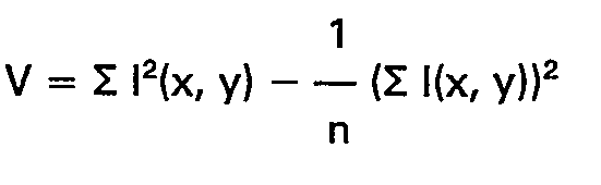
- 5. If V exceeds a threshold for any of the connected regions of S it signifies a partial match. The value V represents the total variability within a region. It is examined to avoid false matches from large uniform areas which may give large correlation.
- Note, if desired, the above algorithm will be implemented in an extended version of the matcher.
- Note, what has been disclosed is merely illustrative of the invention as claimed.
Claims (11)
characterised in that
characterised in that
Applications Claiming Priority (2)
| Application Number | Priority Date | Filing Date | Title |
|---|---|---|---|
| US653213 | 1984-09-24 | ||
| US06/653,213 US4611347A (en) | 1984-09-24 | 1984-09-24 | Video recognition system |
Publications (3)
| Publication Number | Publication Date |
|---|---|
| EP0183347A2 EP0183347A2 (en) | 1986-06-04 |
| EP0183347A3 EP0183347A3 (en) | 1987-10-28 |
| EP0183347B1 true EP0183347B1 (en) | 1990-12-27 |
Family
ID=24619951
Family Applications (1)
| Application Number | Title | Priority Date | Filing Date |
|---|---|---|---|
| EP85306610A Expired EP0183347B1 (en) | 1984-09-24 | 1985-09-17 | Video image recognition system |
Country Status (5)
| Country | Link |
|---|---|
| US (1) | US4611347A (en) |
| EP (1) | EP0183347B1 (en) |
| JP (1) | JPH0661107B2 (en) |
| CA (1) | CA1235514A (en) |
| DE (1) | DE3581173D1 (en) |
Families Citing this family (38)
| Publication number | Priority date | Publication date | Assignee | Title |
|---|---|---|---|---|
| JPS60254279A (en) * | 1984-05-31 | 1985-12-14 | Fuji Electric Co Ltd | Decision of binary coded threshold value |
| JPS61183716A (en) * | 1985-02-08 | 1986-08-16 | Hitachi Ltd | Guiding device |
| US4760604A (en) * | 1985-02-15 | 1988-07-26 | Nestor, Inc. | Parallel, multi-unit, adaptive, nonlinear pattern class separator and identifier |
| US4773099A (en) * | 1985-10-10 | 1988-09-20 | The Palantir Corporation | Pattern classification means for use in a pattern recognition system |
| US5060277A (en) * | 1985-10-10 | 1991-10-22 | Palantir Corporation | Pattern classification means using feature vector regions preconstructed from reference data |
| US5077807A (en) * | 1985-10-10 | 1991-12-31 | Palantir Corp. | Preprocessing means for use in a pattern classification system |
| US4809347A (en) * | 1986-07-18 | 1989-02-28 | Hughes Aircraft Company | Computer vision architecture |
| JP2832008B2 (en) * | 1988-07-29 | 1998-12-02 | キヤノン株式会社 | Image processing system |
| US5031228A (en) * | 1988-09-14 | 1991-07-09 | A. C. Nielsen Company | Image recognition system and method |
| US5248873A (en) * | 1991-06-10 | 1993-09-28 | Synaptics, Incorporated | Integrated device for recognition of moving objects |
| US5380428A (en) * | 1992-04-22 | 1995-01-10 | Product Research & Development | Pump for reverse osmosis system |
| US5450504A (en) * | 1992-05-19 | 1995-09-12 | Calia; James | Method for finding a most likely matching of a target facial image in a data base of facial images |
| JP3549569B2 (en) * | 1993-04-27 | 2004-08-04 | ソニー エレクトロニクス インコーポレイテッド | Target pattern detection method in video |
| DE4322803C2 (en) * | 1993-07-08 | 1998-09-10 | Mohndruck Reinhard Mohn Ohg | Process for monitoring the completeness of individually printed products in online production |
| US5530483A (en) * | 1994-10-11 | 1996-06-25 | Pixel Instruments Corp. | Delay detector apparatus and method for plural image sequences |
| TW367447B (en) * | 1994-12-21 | 1999-08-21 | Canon Kk | Block selection review and editing system |
| DE19713521B4 (en) * | 1997-04-02 | 2004-09-23 | Festo Ag & Co | Device for recognizing incorrectly oriented and / or parts deviating from a predetermined pattern |
| JP3053607B2 (en) * | 1998-04-08 | 2000-06-19 | 三菱電機株式会社 | Data collation method and apparatus |
| US6134298A (en) * | 1998-08-07 | 2000-10-17 | Schick Technologies, Inc. | Filmless dental radiography system using universal serial bus port |
| KR100311952B1 (en) * | 1999-01-11 | 2001-11-02 | 구자홍 | Method of face territory extraction using the templates matching with scope condition |
| US6229541B1 (en) | 1999-09-03 | 2001-05-08 | Isurftv | Use of templates for cost-effective secure linking of video stream objects |
| KR100447268B1 (en) * | 2001-12-18 | 2004-09-07 | 한국전자통신연구원 | Method for eye detection from face images by searching for an optimal binarization threshold |
| US20040038169A1 (en) * | 2002-08-22 | 2004-02-26 | Stan Mandelkern | Intra-oral camera coupled directly and independently to a computer |
| JP4218319B2 (en) * | 2002-11-19 | 2009-02-04 | 日本電気株式会社 | Video browsing system and method |
| US7203338B2 (en) * | 2002-12-11 | 2007-04-10 | Nielsen Media Research, Inc. | Methods and apparatus to count people appearing in an image |
| AU2002362145A1 (en) * | 2002-12-11 | 2004-06-30 | Nielsen Media Research, Inc. | Detecting a composition of an audience |
| US6908307B2 (en) | 2003-02-03 | 2005-06-21 | Schick Technologies | Dental camera utilizing multiple lenses |
| US7245779B2 (en) * | 2003-07-23 | 2007-07-17 | Marvell International Technology Ltd. | Image enhancement employing partial template matching |
| US8411963B2 (en) * | 2008-08-08 | 2013-04-02 | The Nielsen Company (U.S.), Llc | Methods and apparatus to count persons in a monitored environment |
| US8049643B2 (en) | 2009-02-04 | 2011-11-01 | Pete Ness | Vehicle tracking system for vehicle washing |
| US8260055B2 (en) | 2009-03-27 | 2012-09-04 | The Nielsen Company (Us), Llc | Methods and apparatus for identifying primary media content in a post-production media content presentation |
| US8925024B2 (en) | 2009-12-31 | 2014-12-30 | The Nielsen Company (Us), Llc | Methods and apparatus to detect commercial advertisements associated with media presentations |
| US8620088B2 (en) | 2011-08-31 | 2013-12-31 | The Nielsen Company (Us), Llc | Methods and apparatus to count people in images |
| US10152627B2 (en) | 2017-03-20 | 2018-12-11 | Microsoft Technology Licensing, Llc | Feature flow for video recognition |
| US20190236348A1 (en) * | 2018-01-30 | 2019-08-01 | Ncr Corporation | Rapid landmark-based media recognition |
| US11711638B2 (en) | 2020-06-29 | 2023-07-25 | The Nielsen Company (Us), Llc | Audience monitoring systems and related methods |
| US11860704B2 (en) | 2021-08-16 | 2024-01-02 | The Nielsen Company (Us), Llc | Methods and apparatus to determine user presence |
| US11758223B2 (en) | 2021-12-23 | 2023-09-12 | The Nielsen Company (Us), Llc | Apparatus, systems, and methods for user presence detection for audience monitoring |
Family Cites Families (9)
| Publication number | Priority date | Publication date | Assignee | Title |
|---|---|---|---|---|
| FR2106843A5 (en) * | 1970-09-25 | 1972-05-05 | Thomson Csf | |
| JPS4980947A (en) * | 1972-12-11 | 1974-08-05 | ||
| US3930231A (en) * | 1974-06-10 | 1975-12-30 | Xicon Data Entry Corp | Method and system for optical character recognition |
| US3947833A (en) * | 1974-11-20 | 1976-03-30 | The United States Of America As Represented By The Secretary Of The Navy | Automatic target detection system |
| US4030068A (en) * | 1976-01-12 | 1977-06-14 | Decision Data Computer Corporation | Optical character recognition system |
| US4385322A (en) * | 1978-09-01 | 1983-05-24 | View Engineering, Inc. | Pattern recognition apparatus and method |
| US4288782A (en) * | 1979-08-24 | 1981-09-08 | Compression Labs, Inc. | High speed character matcher and method |
| US4410916A (en) * | 1979-08-24 | 1983-10-18 | Compression Labs, Inc. | Dual mode facsimile coding system and method |
| EP0081322A3 (en) * | 1981-12-04 | 1986-07-30 | British Robotic Systems Limited | Component identification systems |
-
1984
- 1984-09-24 US US06/653,213 patent/US4611347A/en not_active Expired - Lifetime
-
1985
- 1985-08-30 CA CA000489847A patent/CA1235514A/en not_active Expired
- 1985-09-17 DE DE8585306610T patent/DE3581173D1/en not_active Expired - Fee Related
- 1985-09-17 EP EP85306610A patent/EP0183347B1/en not_active Expired
- 1985-09-24 JP JP60209028A patent/JPH0661107B2/en not_active Expired - Fee Related
Also Published As
| Publication number | Publication date |
|---|---|
| DE3581173D1 (en) | 1991-02-07 |
| US4611347A (en) | 1986-09-09 |
| EP0183347A3 (en) | 1987-10-28 |
| JPS6184785A (en) | 1986-04-30 |
| CA1235514A (en) | 1988-04-19 |
| EP0183347A2 (en) | 1986-06-04 |
| JPH0661107B2 (en) | 1994-08-10 |
Similar Documents
| Publication | Publication Date | Title |
|---|---|---|
| EP0183347B1 (en) | Video image recognition system | |
| US7957584B2 (en) | Fast object detection for augmented reality systems | |
| US5524065A (en) | Method and apparatus for pattern recognition | |
| US7194134B2 (en) | Hierarchical, probabilistic, localized, semantic image classifier | |
| US5657397A (en) | Preprocessing means for use in a pattern classification system | |
| US6574354B2 (en) | Method for detecting a face in a digital image | |
| US5048107A (en) | Table region identification method | |
| US5048096A (en) | Bi-tonal image non-text matter removal with run length and connected component analysis | |
| US20010041008A1 (en) | Image retrieval device, image retrieval method and storage medium storing similar-image retrieval program | |
| EP0181009B1 (en) | Image processing device and method for controlling the same | |
| US5999653A (en) | Fast techniques for searching images using the Hausdorff distance | |
| JPH0676062A (en) | Picture processor | |
| Cootes et al. | Modelling Object Appearance using The Grey-Level Surface. | |
| US5587927A (en) | Detecting apparatus for detecting a contour of a moving region in a dynamic image | |
| Saber et al. | Region-based shape matching for automatic image annotation and query-by-example | |
| WO2001008098A1 (en) | Object extraction in images | |
| US6795578B1 (en) | Image processing apparatus and method, and storage medium | |
| US6560359B2 (en) | Data processing method and apparatus | |
| US5887081A (en) | Method for fast image identification and categorization of multimedia data | |
| KR20010026397A (en) | Method for comparing similarity of two images and method and apparatus for searching images using the same | |
| US5563957A (en) | Information recognition with transmission between character segmenting and recognition processors | |
| KR100229810B1 (en) | Method for searching image database | |
| JP2585606B2 (en) | Image pattern search method | |
| Shlien | Multifont character recognition for typeset documents | |
| Singh | Unsupervised segmentation of medical images using DCT coefficients |
Legal Events
| Date | Code | Title | Description |
|---|---|---|---|
| PUAI | Public reference made under article 153(3) epc to a published international application that has entered the european phase |
Free format text: ORIGINAL CODE: 0009012 |
|
| AK | Designated contracting states |
Kind code of ref document: A2 Designated state(s): DE FR GB |
|
| PUAL | Search report despatched |
Free format text: ORIGINAL CODE: 0009013 |
|
| AK | Designated contracting states |
Kind code of ref document: A3 Designated state(s): DE FR GB |
|
| 17P | Request for examination filed |
Effective date: 19880418 |
|
| 17Q | First examination report despatched |
Effective date: 19890720 |
|
| GRAA | (expected) grant |
Free format text: ORIGINAL CODE: 0009210 |
|
| AK | Designated contracting states |
Kind code of ref document: B1 Designated state(s): DE FR GB |
|
| PG25 | Lapsed in a contracting state [announced via postgrant information from national office to epo] |
Ref country code: FR Effective date: 19901227 |
|
| REF | Corresponds to: |
Ref document number: 3581173 Country of ref document: DE Date of ref document: 19910207 |
|
| EN | Fr: translation not filed | ||
| PG25 | Lapsed in a contracting state [announced via postgrant information from national office to epo] |
Ref country code: GB Effective date: 19910917 |
|
| PLBE | No opposition filed within time limit |
Free format text: ORIGINAL CODE: 0009261 |
|
| STAA | Information on the status of an ep patent application or granted ep patent |
Free format text: STATUS: NO OPPOSITION FILED WITHIN TIME LIMIT |
|
| 26N | No opposition filed | ||
| GBPC | Gb: european patent ceased through non-payment of renewal fee | ||
| PGFP | Annual fee paid to national office [announced via postgrant information from national office to epo] |
Ref country code: DE Payment date: 20020916 Year of fee payment: 18 |
|
| PG25 | Lapsed in a contracting state [announced via postgrant information from national office to epo] |
Ref country code: DE Free format text: LAPSE BECAUSE OF NON-PAYMENT OF DUE FEES Effective date: 20040401 |