EP0183950A1 - Method of processing liquid within a tube - Google Patents
Method of processing liquid within a tube Download PDFInfo
- Publication number
- EP0183950A1 EP0183950A1 EP85113154A EP85113154A EP0183950A1 EP 0183950 A1 EP0183950 A1 EP 0183950A1 EP 85113154 A EP85113154 A EP 85113154A EP 85113154 A EP85113154 A EP 85113154A EP 0183950 A1 EP0183950 A1 EP 0183950A1
- Authority
- EP
- European Patent Office
- Prior art keywords
- liquid
- plug
- tube
- sample
- interest
- Prior art date
- Legal status (The legal status is an assumption and is not a legal conclusion. Google has not performed a legal analysis and makes no representation as to the accuracy of the status listed.)
- Granted
Links
Images
Classifications
-
- G—PHYSICS
- G01—MEASURING; TESTING
- G01N—INVESTIGATING OR ANALYSING MATERIALS BY DETERMINING THEIR CHEMICAL OR PHYSICAL PROPERTIES
- G01N35/00—Automatic analysis not limited to methods or materials provided for in any single one of groups G01N1/00 - G01N33/00; Handling materials therefor
- G01N35/08—Automatic analysis not limited to methods or materials provided for in any single one of groups G01N1/00 - G01N33/00; Handling materials therefor using a stream of discrete samples flowing along a tube system, e.g. flow injection analysis
-
- G—PHYSICS
- G01—MEASURING; TESTING
- G01N—INVESTIGATING OR ANALYSING MATERIALS BY DETERMINING THEIR CHEMICAL OR PHYSICAL PROPERTIES
- G01N30/00—Investigating or analysing materials by separation into components using adsorption, absorption or similar phenomena or using ion-exchange, e.g. chromatography or field flow fractionation
- G01N30/02—Column chromatography
- G01N30/04—Preparation or injection of sample to be analysed
- G01N30/06—Preparation
-
- G—PHYSICS
- G01—MEASURING; TESTING
- G01N—INVESTIGATING OR ANALYSING MATERIALS BY DETERMINING THEIR CHEMICAL OR PHYSICAL PROPERTIES
- G01N30/00—Investigating or analysing materials by separation into components using adsorption, absorption or similar phenomena or using ion-exchange, e.g. chromatography or field flow fractionation
- G01N30/02—Column chromatography
- G01N30/04—Preparation or injection of sample to be analysed
- G01N30/24—Automatic injection systems
Definitions
- the present invention relates to a method of processing liquid within a tube as recited in the pre-characterizing part of claim 1. Such methods are used in the chemical preparation of samples for analysis in various types of systems, such as chromatographs.
- the invention may in particular be applied as an automatic preparation method in which one or a small number of samples are pre-treated prior to analysis.
Abstract
Description
- The present invention relates to a method of processing liquid within a tube as recited in the pre-characterizing part of
claim 1. Such methods are used in the chemical preparation of samples for analysis in various types of systems, such as chromatographs. The invention may in particular be applied as an automatic preparation method in which one or a small number of samples are pre-treated prior to analysis. - In a typical chromatograph, a sample is injected into a solvent stream which is passed through a separation column (e.g., an adsorption, ion exchange or gel permeation column). As a result of chemical and physical interaction between the chemical components of the sample and the separation column, each component passes at a different rate through the separation column. After passage through the separation column, the solvent stream passes through a detector (e.g., a spectrophotometer) which detects each component as it passes through the detector.
- Unfortunately, a test sample cannot usually be inserted, without processing, into the detector path because test samples typically contain components that degrade operation of the separation column and/or interfere with detection of the sample component of interest. Therefore, prior to inserting into the solvent stream through the detector, the test sample must go through a sample preparation stage that is often quite lengthy and expensive. These steps can include sample steps such as precipitation, filtration, centrifugation, changes in concentration, extraction, chemical derivatization, and/or separation by passage through a distillation column. Such sample preparation can also be very elaborate such as in analysis of complex organic molecules in which such molecules are chemically broken into constituent parts and these parts are converted into derivatives more suitable for passage through the separation column and the detector. Typically, these preparation steps are performed manually and are therefore time consuming and expensive. To reduce the cost and duration of this preparation stage, it is advantageous to automate this preparation stage.
- In one system known as the Baker 10 Extraction System, liquid-solid extraction times are reduced by use of a vacuum system that allows up to 10 columns to be inserted in parallel into a vacuum system for liquid-solid extraction of up to 10 samples concurrently. Unfortunately, introduction of samples into each column and insertion of the columns into the vacuum system is performed manually so that the extraction step is still time consuming. Another automation technique uses robots to substantially duplicate the procedures now performed manually. Such an approach is flexible and has the advantage of utilizing fully developed chemical processing steps, but it is inordinately expensive.
- Liquid-liquid extraction is far more popular than liquid-solid extraction for sample clean-up and pre-concentration because of its predictability, simplicity, reproducibility, selectivity and flexibility. A continous-flow analysis technique is introduced in the article L. J. Skeggs, Am. J. Clin. Pathol., 28, 311, (1957) and in an article by J.C. Kraak entitled "Automated Sample Handling by Extraction Techniques", and published in Trends in Analytical Chemistry, vol. 2, no. 8, 1983, a continuous-flow technique is described for liquid-liquid extraction. In the process presented by Kraak, a detector flow path is utilized that includes an inlet for the solvent carrier, an inlet for insertion of air bubbles, and an inlet for insertion of sample plugs. To prevent interference with the separation column and detector, a phase separator is included to remove the air and resulting waste phase before passage through the column and detector. In this technique, Bolus flow is utilized to exhance the liquid-liquid extraction process.
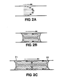
- Bolus flow can be understood by reference to Figures 2A-2C. When a volume of sample fluid is drawn into or injected into a narrow tube, the sample fills the tube over a continuous region referred to herein as a plug. When a plug travels through a tube in a direction indicated by the arrow above each figure, a parabolic distribution of velocity results as shown in Figure 2A. This type of flow, known as Taylor flow, is disadvantageous in transferring a sample plug because the portion of the sample plug closer to the wall travels slower than the portion in the center of the tube. This flow profile extends the plug into liquid on each side of the plug, thereby producing an elongation and dilution of the sample plug, thereby reducing the detectability of the sample. This dilution and elongation is prevented by sandwiching the sample plug between a pair of air bubbles as in Figure 2B. The transfer of plugs sandwiched between gas bubbles is referred to as segmented flow. Because flow of the sample plug past the meniscus between each bubble and the sample plug is prevented, a flow pattern within each sample plug is produced like that shown in Figure 2B. Such flow is called Bolus flow and is useful in liquid-liquid extractions as shown in Figure 2C. In that figure, a
first liquid 21 and asecond liquid 22, which are immiscible in one another, are inserted next to one another in the solvent stream and are sandwiched between a pair of air bubbles. The resulting Bolus flow in each of these liquid plugs continually renews the portion of each liquid at or near the interface between these two liquids. In order to extract the solute inliquid 21,liquid 22 is selected not only to be immiscible withliquid 21, but also to have a higher coefficient of solubility for the solute than doesliquid 21. When the volume ofliquid 22 is less than that ofliquid 21, this can increase the resulting concentration of the solute inliquid 22 over the original concentration inliquid 21, thereby increasing the signal amplitude whenliquid 22 is passed through the detector. In the case in whichsolvents - Unfortunately, as the article by J.C. Kraak indicates, in the case of liquid-liquid extraction, the volumetric ratio of
liquid 21 toliquid 22 is limited to approximately four so that the ratio of the resulting concentration of sample solute inliquid 22 to the original concentration inliquid 21 must be less than four. Also, the phase separator required to removeliquid 21 and the air bubbles before passage of the stream through the detector, broadens the sample plugs and can transfer liquid from one plug to another. For large sample plugs, this is not critical because the concentration profile of the plug after passage through the phase separator still has a plateau within which a representative sample aliquot can be withdrawn. However, for the small samples that are increasingly utilized in chemical analyses, the broadening by the phase separator significantly affects the detection quality. The continuous flow liquid-liquid process is also rather inflexible because one setup is only suitable for one type of analysis. In addition, the insertion of carrier solvent, sample and air through separate inlets requires accurate timing to be able to insert sample plugs and air bubbles at the selected locations in the solvent stream. - The present invention as claimed in
claim 1, seen in relation to the apparatus disclosed in the Kraak article discussed above, provides a method of processing liquid within a tube wherein high accuracy is more easily attained in the preparation of small chemical samples. - In the method according to the claim preamble wherein a plug of liquid is drawn into and moved along a tube with a pump, the technical problem set out above is solved by controlling the pump to stop the movement of the plug within the tube at least once in preparation for a following processing step to be applied to the liquid in the plug.
- As a result of having the plug come to rest within the tube in a controlled fashion in preparation for processing, the processing can be done with high accuracy without the need for critical timing in operations taking place "on the fly". The plug may be stopped at an exact location for processing to take place undisturbedly.
- The subclaims are directed to the following preferred embodiments of the invention:
- In accordance with claim 2 fluid may be ejected from the entrance end of the tube after processing to facilitate hookup of the pump to the other end of the tube.
- In accordance with claim 3 gas bubbles may be drawn into the tube to sandwich liquid plugs between them so that bolus flow results in the liquid to enhance internal mixing.
- In accordance with claim 4 two or more adjacent plugs may be drawn from different liquids to induce mixing, extraction or chemical reactions therebetween during movement within the tube for processing purposes.
- In accordance with claim 5 liquid-liquid extraction may be accomplished by drawing adjacent plugs from properly selected immiscible fluids and moving them along the tube jointly.
- In accordance with claim 6 the efficiency of liquid-liquid extraction may be increased substantially by extracting solute from two or more plugs of a sample fluid with one plug of solvent.
- In acordance with claim 7 miscible fluids may be mixed by moving them along the tube jointly. In accordance with claims 8 and 9, discontinuous processing steps may take place at certain selected locations within the tube.
Claims 10 and 11 are directed to preferred methods of removing processed liquid from the tube for analysis. - In accordance with the illustrated preferred embodiment, a method and associated apparatus are presented for automatic pre-treatment of samples prior to passage of the samples through a detector. The apparatus utilizes a syringe that includes a motor for electrical control of syringe plunger motion. The syringe is connected to a sample preparation tube that includes a needle that has an associated motor that can raise and lower the needle. The syringe functions as a bidirectional pump which can controllably move samples in either direction along the sample preparation tube. An autosampler is included to electro-mechanically insert selected sample vials under the needle.
- The autosampler, needle and syringe are all controlled by a microprocessor to automate preparation of samples. The needle and autosampler are controlled to place under the needle a vial containing a sample to be processed. The needle is lowered into the vial, a sample plug is drawn through the needle into the sample preparation tube and then the needle is removed from the sample vial. The syringe is then controlled to move the sample in any manner desired along the sample preparation tube. Motion of the sample as a result of control of the syringe creates far greater flexibility than that present in an apparatus that only utilizes the syringe to draw in a sample which is then switched into a continuous stream of solvent. In this latter apparatus, the processing of the sample is dictated by the arrangement for the flow of the solvent. In contrast to that apparatus, control of sample plug motion by control of the syringe enables the sample plug to be moved at will. For example, the sample plug can be moved to induce Bolus flow for mixing or extraction. The sample plug can be moved into a section of the sample preparation tube within a heater element and then left there as long as desired. Another section of the sample preparation tube can contain a detector for final detection of the sample or for intermediate detection to monitor the preparation of the sample.
- The syringe and needle control can be correlated to draw air into the needle just before and just after drawing in a particular liquid, thereby segmenting the fluid stream to isolate that liquid from the rest of the fluid stream. Such a sample method of producing segments in the fluid stream avoids the need for close timing between bubble insertion through one inlet and sample injection through another inlet as is required in the continuous flow processes discussed earlier. The needle, syringe and autosampler can be coordinated to insert a variety of samples and/or processing fluids into the tube in any order desired, thereby enabling processing of several distinct sample plugs concurrently and/or inserting various other reagents to interact with the sample plug. The same plug of extraction fluid can be used to extract sample solute from a succession of sample plugs to produce an increase in concentration greater than four. The processing of a given sample can terminate by ejection into a sample vial for use later or elsewhere or can terminate by passage through the detector used to measure the sample.
- A transfer tube is used to transfer a sample from the sample preparation path into a detector path. This transfer process can also be used to separate air bubbles and waste phase from the sample to be transferred. Since, in this modified apparatus, the high pressure carrier solvent used to force fluid through the separation column is not passed through the needle, the sample preparation path need not be adapted to operate with high internal pressures.
- The invention will now be described in greater detail with reference to the accompanying drawings. In the drawings,
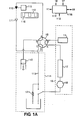
- Figure 1A is a block diagram of a prior art chromatograph.
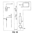
- Figure 1B illustrates the functional operation of the 6-port valve of Figure 1A.
- Figure 2A shows the velocity profile of Taylor flow.
- Figure 2B shows the flow pattern in Bolus flow.
- Figure 2C illustrates the enhancement of liquid-liquid extraction due to Bolus flow.
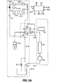
- Figure 3A is a block diagram of a preferred apparatus wherein the method according to the invention may be performed.
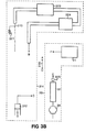
- Figure 3B illustrates the functional operation of the 6-port valve of Figure 3A.
- In Figure 1A is illustrated a chromatograph having an automatic sample injection system. In accordance with the preferred embodiment of the present invention, it was observed that this system can be modified structurally and operated in a new way that not only enables samples to be injected into a solvent stream for detection, but also enables automated processing of the samples before injection into the solvent stream.
- The system in Figure 1A includes a
solvent source 11 that provides a stream of solvent into which sample plugs are inserted. Typically,source 11 includes a set of solvent sources, each of which is connected to an associated one of a set of metering pumps.Source 11 also contains a valve that controllably connects one of the metering pumps through a high pressure booster and a damper to a 6-port rotary valve 16. The high pressure booster increases the pressure and the damper smoothes out pressure variations introduced by the booster. -
Valve 16 serves to controllably connect the system in a manner more clearly illustrated in Figure 1B. In a first rotary position, port F is connected to port E so that solvent flows fromsource 11 to the input of acolumn 17 and then on through adetector 18. The path indicated aspath 19 will be referred to herein as the detector path. In a second rotary position, port F is connected to port A and port D is connected to port E so that a path segment AD containing aneedle 110 and aneedle seat 111 is inserted intodetector path 19. - In the second rotary position, port B is connected to port C so that a
syringe 112 is connected directly to atube 113 that is open to the ambient atmosphere. The path segment indicated aspath 114 will be referred to herein as the sample preparation path. In the first rotary position, port B is connected to port A and port D is connected to port C so thatneedle 110 andseat 111 are inserted into the sample preparation path. Thus, in the first rotary position,needle 110 andseat 111 are inserted into the sample preparation path and in the secondrotary position needle 110 andseat 111 are inserted into the detector path. - As shown in Figure 1A,
needle 110 is connected to amotor 115 which can raise and lower the needle. The needle is raised to enable insertion of asample vial 116 under the needle.Motor 115 lowers the needle into a sample vial for extraction of a sample from the sample vial.Syringe 112 includes a motor which can be activated to draw sample fluid intoneedle 110. When the needle is lowered with no vial inserted, then the needle fits securely intoseat 111. Selection of a vial and insertion of the vial underneedle 110 is controlled by anautosampler 117 such as the HP 79847A autosampler manufactured by Hewlett-Packard Company.Valve 16,motor 115,autosampler 17,syringe 112,detector 18 and the metering pumps are all connected to and controlled by a processor such asmicroprocessor 118. - This system is a continuous flow system in which solvent is continuously flowing in the
detector path 19. In normal operation,valve 16 is set into the first rotational position to rinse the column with solvent and to place the needle intosample path 114.Needle 110,autosampler 117 andsyringe 112 are controlled to select a sample vial, place the vial under the needle, withdraw a sample from the vial, and then reinsert the needle inseat 111.Valve 16 then switches path segment AD into the detector path so that the flowing solvent passes through the needle and carries the sample intocolumn 17. The section of the fluid stream containing the injected sample is referred to as the sample plug.Valve 16 then returns to the first rotary position so thatneedle 110 is reinserted into the sample path for withdrawal of a subsequent sample from a sample vial. - In Figure 3A is shown a modification of the apparatus of Figure 1A that is more suitable than that shown in Figure 1A for processing the samples before injecting them in the solvent stream in
detector path 19. Those elements in Figures 3A and 3B that are equivalent to elements in Figure 1A are denoted with corresponding reference numerals. In particular, an element having a corresponding element designated by numeral 1x or lxy in Figure 1A is denoted as 3x or 3xy, respectively, to show this correlation. In Figure 3A, the elements are connected tovalve 36 in a configuration that is more convenient than the configuration in Figure 1A. The effect of the reconfiguration is most easily seen by comparison of Figure 3B with Figure 1B. In the new configuration, operation ofvalve 36 functions to insert atransfer tube 319 either into adetector path 39 or into asample preparation path 314. One advantage of this is thatneedle 310 andseat 311 are not transferred into the high pressure detector path and therefore need not be designed to seal at high pressures. More significantly, the transfer tube can be selected to have a smaller volume than the needle, seat and associated tubing, which is advantageous in transferring small sample plugs from the sample preparation path to the detector path. The utility of the sample preparation tube will be discussed in greater detail below. - Sample preparation occurs in a
sample preparation path 314 containing asample preparation tube 320 and aseat 311.Sample preparation tube 320 includes aneedle 310 that fits intoseat 311.Seat 311 also includes atube 313 that is open to the atmosphere through aflow restriction 321. Aswitch 322 is included to enable diversion of solvent intotube 313 to produce a reverse-directed flow of solvent throughneedle 310,sample preparation tube 320 andsyringe 312 to allow flushing of those three elements. The flow path that includessample preparation tube 320,seat 311 andsyringe 312 is referred to herein as the sample preparation path and is referenced bynumeral 314. - A
motor 315 is connected toneedle 310 to raise and lower the needle to enable containers, such asvial 316, to be inserted under the needle. When no vial is present under the needle, the needle can be lowered intoseat 311 to form a continuous path fromsample preparation tube 320 totube 313. Anautosampler 317 controllably selects, inserts and retrieves vials underneedle 310.Elements processor 318 to enable automation of the sample preparation and sample detection processes. - Under the control of
processor 318, a sample plug is generated, pre-processed and then detected in the following manner.Valve 36 is placed in the first rotary position and solvents are controllably supplied throughcolumn 37 to rinse the column.Sample preparation path 314 is disjoint fromdetector path 39 so that sample preparation can be taking place concurrently with rinsing of the column or detection of a sample. To prepare a sample,needle 310 is raised, avial 316 is inserted under the needle and the needle is lowered into the sample.Syringe 312 is controlled to draw a selected amount of sample throughneedle 310 to form a sample plug. - If it is desired to segment the sample plug, then the needle and syringe are controlled to draw in through the needle a small bubble of air just before the needle is lowered into the sample and just after the needle is lifted out of the sample. This method of segmenting a sample is much simpler than prior methods which insert sample and air through separate inlets. In prior systems a phase separator is needed to remove the air bubbles. Unfortunately, a phase separator typically introduces undesired band broadening and also introduces contamination by transfer of liquid from one sample plug to another. Especially for larger reaction and extraction times, this method requires large amounts of sample. In addition, because each application requires a particular setup of the hardware for that application, flexibility is low. Development of a method is time consuming because interfacing with other instruments can only be done by a real time program.
- In contrast to these prior sample preparation methods, the present approach to segmentation avoids all this. One or only a limited number of sample plugs are manipulated by a reversible pump in a small volume. As discussed below, the same structure that allows phase separation in the new system, also functions as the interface to the measuring system, thereby reducing even more the volume of sample required. The reversibility, control oabiUty and low volume of the phase separator-interface also enable improved control over process parameters and greater flexibility of sample preparation. Because a single sample plug can be manipulated at a given time for processing, there is no need for real-time programming.
- As an example of the increased flexibility, an air bubble can be inserted at a selected point in a plug or between adjacent plugs by moving the plugs in the sample preparation path to bring the selected point to the tip of
needle 319. The needle is then withdrawn fromseat 311, an air bubble is drawn in, and then the needle is reinserted intoseat 311 for further processing and/or detection. - The transfer tube enables efficient transfer of a sample into
detector path 39 and also enables simple separation of air bubbles and undesired solvents without introducing the broadening and segment- tosegment transfers associated with existing separators. The volume oftransfer tube 319 is selected to be substantially equal to the volume of the sample plug to be transferred todetector path 39. With this choice of volume, when the syringe is controlled to place a segmented sample intotransfer tube 319, the segmentation bubbles on each side of the sample plugs are outside of the transfer tube and therefore are not transferred todetector path 39. In those cases where it is desired to ensure transfer of all of the sample plug, the volume of the transfer tube is slightly greater than the volume of the sample plug. In those cases where it is important to transfer only liquid from the sample plug, the volume of the transfer tube is slightly smaller than the volume of the sample plug. In a similar manner, in an extraction process, the extraction liquid and sample solute can be transferred to the detector path without transferring the solvent in which the solute was initially dissolved.Transfer tube 319 is easily replaced with tubes of other volumes for transfer of sample plugs of various lengths. - Because the stroke of
syringe 312 required to move a sample fromneedle 310 intotube 319 will vary with variations in the volume of components of the sample preparation path, it may be necessary to calibrate the system. Such calibration is easily achieved, by utilizing, for example, a clear transfer tube that enables visual determination of the stroke required to move the front edge of a sample plug to point B and the stroke required to move the front edge of the sample plug to point C. That stroke is then retained in processor memory to control subsequent transfers intotube 319. Alternatively, to avoid needing to recalibrate each time atransfer tube 319 is replaced by another transfer tube, a sensor, such asbubble sensor 325 in Figure 3B, can be included at point C and/or point B. - For more complicated processing,
processing tube 320 can include various modules such asmodules Module 323 is a parameter controller (e.g., an oven) which is used to regulate some parameter of the sample plug.Module 324 is a detector (e.g., a pH meter). Such detectors insample preparation path 314 can be used not only to monitor and control processing of the sample, but, when appropriate, can be used for final detection of the processed sample. In this latter case,detector path 39 can be eliminated from the apparatus. Unlike in the prior continuous flow processes, the present process allows a sample to be moved insample preparation tube 320 to an oven and left at that point for any time period desired. It should be noted thatsyringe 312 functions as a reversible pump which moves fluid insample preparation tube 320 in either direction, thereby also inducing associated fluid flow across the tip of the needle. The syringe is a particularly attractive pump because of its simplicity, its ease of activation and control, and its ability to move a sample plug accurately within a continuous range of distances. Similarly, fluids can be supplied to the tip ofneedle 310 by means other thanautosampler 317. For example,tube 313 can be connected at a tee to a tube in which fluid flows past the tee. In such a system, the fluid may be, but need not be, segmented. The syringe is then controlled to withdraw selected portions of this fluid stream to form liquid plugs intube 320. The system could also be connected to a robotic system, which delivers the sample in a fluid form. Interfacing with other systems is also possible by use in the other system of a transfer tube that can be controllably inserted intosample preparation path 314.
Claims (11)
to create bolus flow within the liquid in the tube while it is moving therein.
so that a transfer of the solute of interest to the solvent liquid results during the joint movement of the first plug and the second plug within the tube (320).
so that a mixing of the first liquid with the second liquid results during the joint movement of the first plug and the second plug within the tube (320).
Applications Claiming Priority (2)
| Application Number | Priority Date | Filing Date | Title |
|---|---|---|---|
| US66212884A | 1984-10-18 | 1984-10-18 | |
| US662128 | 1984-10-18 |
Publications (2)
| Publication Number | Publication Date |
|---|---|
| EP0183950A1 true EP0183950A1 (en) | 1986-06-11 |
| EP0183950B1 EP0183950B1 (en) | 1990-05-16 |
Family
ID=24656479
Family Applications (1)
| Application Number | Title | Priority Date | Filing Date |
|---|---|---|---|
| EP85113154A Expired - Lifetime EP0183950B1 (en) | 1984-10-18 | 1985-10-17 | Method of processing liquid within a tube |
Country Status (3)
| Country | Link |
|---|---|
| EP (1) | EP0183950B1 (en) |
| JP (1) | JPH0684962B2 (en) |
| DE (1) | DE3577750D1 (en) |
Cited By (10)
| Publication number | Priority date | Publication date | Assignee | Title |
|---|---|---|---|---|
| US4784962A (en) * | 1986-02-26 | 1988-11-15 | Hewlett-Packard Company | Mixture of amino acid derivatives, process of producing the mixture and use of the mixture for quantitative determination of the amino acids |
| EP0360604A2 (en) * | 1988-09-23 | 1990-03-28 | Spectra-Physics, Inc. | Liquid sample movement |
| WO2003104814A2 (en) * | 2002-01-01 | 2003-12-18 | Phynexus, Inc. | Biomolecule open channel solid phase extraction systems and methods |
| WO2004103564A1 (en) * | 2003-05-19 | 2004-12-02 | Hans-Knöll-Institut für Naturstoff-Forschung e.V. | Device and method for positioning and removing fluid compartments that are embedded in a separation medium |
| US7122640B2 (en) | 2002-06-10 | 2006-10-17 | Phynexus, Inc. | Open channel solid phase extraction systems and methods |
| US7151167B2 (en) | 2002-06-10 | 2006-12-19 | Phynexus, Inc. | Open channel solid phase extraction systems and methods |
| US7465382B2 (en) | 2001-06-13 | 2008-12-16 | Eksigent Technologies Llc | Precision flow control system |
| US7695603B2 (en) | 2001-06-13 | 2010-04-13 | Eksigent Technologies, Llc | Electroosmotic flow controller |
| US7879621B2 (en) | 2003-05-08 | 2011-02-01 | Phynexus, Inc. | Open channel solid phase extraction systems and methods |
| FR3105016A1 (en) * | 2019-12-23 | 2021-06-25 | Commissariat A L'energie Atomique Et Aux Energies Alternatives | Devices and methods for mixing liquids back and forth between pump and measuring cell, and physico-chemical analysis of the liquids thus mixed |
Families Citing this family (2)
| Publication number | Priority date | Publication date | Assignee | Title |
|---|---|---|---|---|
| JPH0740029B2 (en) * | 1987-05-13 | 1995-05-01 | 積水化学工業株式会社 | Method for treating sample containing DNA |
| JP5397269B2 (en) * | 2010-02-26 | 2014-01-22 | 株式会社島津製作所 | Sample introduction device |
Citations (5)
| Publication number | Priority date | Publication date | Assignee | Title |
|---|---|---|---|---|
| US2797149A (en) * | 1953-01-08 | 1957-06-25 | Technicon International Ltd | Methods of and apparatus for analyzing liquids containing crystalloid and non-crystalloid constituents |
| US2933293A (en) * | 1956-09-12 | 1960-04-19 | Technicon Instr | Method of intermixing a plurality of liquids of different specific gravities |
| GB1238395A (en) * | 1969-07-28 | 1971-07-07 | ||
| DD101014A1 (en) * | 1973-01-04 | 1973-10-12 | ||
| WO1984002000A1 (en) * | 1981-01-10 | 1984-05-24 | Shaw Stewart P D | Chemical droplet reactor |
Family Cites Families (4)
| Publication number | Priority date | Publication date | Assignee | Title |
|---|---|---|---|---|
| JPS6035894Y2 (en) * | 1978-04-28 | 1985-10-24 | 株式会社島津製作所 | automatic analyzer |
| JPS5525882A (en) * | 1978-08-14 | 1980-02-23 | Kazuo Fukuda | Cassette for tape recorder |
| JPS5838856A (en) * | 1981-08-31 | 1983-03-07 | Kyoto Daiichi Kagaku:Kk | Automatic liquid chromatograph apparatus |
| JPS58113748A (en) * | 1981-12-26 | 1983-07-06 | Jeol Ltd | Prelabeling device |
-
1985
- 1985-10-17 EP EP85113154A patent/EP0183950B1/en not_active Expired - Lifetime
- 1985-10-17 DE DE8585113154T patent/DE3577750D1/en not_active Expired - Fee Related
- 1985-10-18 JP JP60233110A patent/JPH0684962B2/en not_active Expired - Lifetime
Patent Citations (5)
| Publication number | Priority date | Publication date | Assignee | Title |
|---|---|---|---|---|
| US2797149A (en) * | 1953-01-08 | 1957-06-25 | Technicon International Ltd | Methods of and apparatus for analyzing liquids containing crystalloid and non-crystalloid constituents |
| US2933293A (en) * | 1956-09-12 | 1960-04-19 | Technicon Instr | Method of intermixing a plurality of liquids of different specific gravities |
| GB1238395A (en) * | 1969-07-28 | 1971-07-07 | ||
| DD101014A1 (en) * | 1973-01-04 | 1973-10-12 | ||
| WO1984002000A1 (en) * | 1981-01-10 | 1984-05-24 | Shaw Stewart P D | Chemical droplet reactor |
Non-Patent Citations (2)
| Title |
|---|
| ANALYTICAL CHEMISTRY, vol. 53, no. 12, October 1981, pages 1403A-1418A, Easton, Pennsylvania, US; D.A. BURNS "Automated sample preparation" * |
| TRENDS IN ANALYTICAL CHEMISTRY, vol. 2, no. 8, August 1983, pages 183-187, Cambridge, GB; J.C. KRAAK: "Automated sample handling by extraction techniques" * |
Cited By (16)
| Publication number | Priority date | Publication date | Assignee | Title |
|---|---|---|---|---|
| US4784962A (en) * | 1986-02-26 | 1988-11-15 | Hewlett-Packard Company | Mixture of amino acid derivatives, process of producing the mixture and use of the mixture for quantitative determination of the amino acids |
| EP0360604A2 (en) * | 1988-09-23 | 1990-03-28 | Spectra-Physics, Inc. | Liquid sample movement |
| EP0360604A3 (en) * | 1988-09-23 | 1991-01-30 | Spectra-Physics, Inc. | Liquid sample movement |
| US8685218B2 (en) | 2001-06-13 | 2014-04-01 | Ab Sciex Llc | Precision flow control system |
| US7465382B2 (en) | 2001-06-13 | 2008-12-16 | Eksigent Technologies Llc | Precision flow control system |
| US7695603B2 (en) | 2001-06-13 | 2010-04-13 | Eksigent Technologies, Llc | Electroosmotic flow controller |
| US7927477B2 (en) | 2001-06-13 | 2011-04-19 | Ab Sciex Llc | Precision flow control system |
| US8795493B2 (en) | 2001-06-13 | 2014-08-05 | Dh Technologies Development Pte. Ltd. | Flow control systems |
| WO2003104814A2 (en) * | 2002-01-01 | 2003-12-18 | Phynexus, Inc. | Biomolecule open channel solid phase extraction systems and methods |
| WO2003104814A3 (en) * | 2002-06-10 | 2004-11-11 | Phynexus Inc | Biomolecule open channel solid phase extraction systems and methods |
| US7122640B2 (en) | 2002-06-10 | 2006-10-17 | Phynexus, Inc. | Open channel solid phase extraction systems and methods |
| US7151167B2 (en) | 2002-06-10 | 2006-12-19 | Phynexus, Inc. | Open channel solid phase extraction systems and methods |
| US7879621B2 (en) | 2003-05-08 | 2011-02-01 | Phynexus, Inc. | Open channel solid phase extraction systems and methods |
| WO2004103564A1 (en) * | 2003-05-19 | 2004-12-02 | Hans-Knöll-Institut für Naturstoff-Forschung e.V. | Device and method for positioning and removing fluid compartments that are embedded in a separation medium |
| FR3105016A1 (en) * | 2019-12-23 | 2021-06-25 | Commissariat A L'energie Atomique Et Aux Energies Alternatives | Devices and methods for mixing liquids back and forth between pump and measuring cell, and physico-chemical analysis of the liquids thus mixed |
| WO2021130424A1 (en) * | 2019-12-23 | 2021-07-01 | Commissariat A L'energie Atomique Et Aux Energies Alternatives | Devices and methods for mixing liquids by moving said liquids back and forth between a pump and a measuring cell, and physicochemical analysis of the liquids mixed in this manner |
Also Published As
| Publication number | Publication date |
|---|---|
| EP0183950B1 (en) | 1990-05-16 |
| JPS6197567A (en) | 1986-05-16 |
| DE3577750D1 (en) | 1990-06-21 |
| JPH0684962B2 (en) | 1994-10-26 |
Similar Documents
| Publication | Publication Date | Title |
|---|---|---|
| EP0022654B1 (en) | Liquid handling device | |
| US8048312B2 (en) | Separation analyzer | |
| EP0183950B1 (en) | Method of processing liquid within a tube | |
| JP2004531738A (en) | High-speed sample preparation and analysis system and method using column chromatography | |
| EP1529211A1 (en) | Systems and methods for high-throughput microfluidic sample analysis | |
| US10677766B2 (en) | Volumetric flow regulation in multi-dimensional liquid analysis systems | |
| Kubá | Liquid-liquid extraction flow injection analysis | |
| US20040076996A1 (en) | Gene analysis method and analyzer therefor | |
| WO2005011832A2 (en) | A simultaneous multi-colum liquid chromatograph for direct sampling of an array of liquid samples | |
| JP2006119136A (en) | Solid phase extracting apparatus and method therefor | |
| EP0868664B1 (en) | Multi-cycle loop injection for trace analysis by ion chromatography apparatus and method | |
| US4816226A (en) | Apparatus for continuous flow injection solvent extraction analysis | |
| EP2214010A2 (en) | High throughput autosampler | |
| EP0253519B1 (en) | Sample handling system | |
| Válcarcel et al. | Coupling continuous sample treatment systems to capillary electophoresis | |
| Kuldvee et al. | Nonconventional samplers in capillary electrophoresis | |
| US20020106319A1 (en) | Sequential injection liquid-liquid extraction | |
| WO1998054579A1 (en) | Carrierless sequential injection analysis | |
| US4057997A (en) | Sample preparation | |
| WO2002101381A1 (en) | Liquid chromatograph and analyzing system | |
| JPH03163357A (en) | Method and apparatus for analyzing catecholamine | |
| Burguera et al. | Liquid sample introduction devices in flow injection atomic spectroscopy. Invited lecture | |
| Kubáň et al. | Sampling and quantitative analysis in capillary electrophoresis | |
| US20040180449A1 (en) | Multidimensional chromatography with ion exchange solid phase extraction | |
| US20200348326A1 (en) | Fluidic Sample Pretreatment Device |
Legal Events
| Date | Code | Title | Description |
|---|---|---|---|
| PUAI | Public reference made under article 153(3) epc to a published international application that has entered the european phase |
Free format text: ORIGINAL CODE: 0009012 |
|
| AK | Designated contracting states |
Kind code of ref document: A1 Designated state(s): DE FR GB IT NL |
|
| 17P | Request for examination filed |
Effective date: 19861120 |
|
| 17Q | First examination report despatched |
Effective date: 19880316 |
|
| GRAA | (expected) grant |
Free format text: ORIGINAL CODE: 0009210 |
|
| AK | Designated contracting states |
Kind code of ref document: B1 Designated state(s): DE FR GB IT NL |
|
| REF | Corresponds to: |
Ref document number: 3577750 Country of ref document: DE Date of ref document: 19900621 |
|
| ET | Fr: translation filed | ||
| ITF | It: translation for a ep patent filed |
Owner name: MODIANO & ASSOCIATI S.R.L. |
|
| PLBE | No opposition filed within time limit |
Free format text: ORIGINAL CODE: 0009261 |
|
| STAA | Information on the status of an ep patent application or granted ep patent |
Free format text: STATUS: NO OPPOSITION FILED WITHIN TIME LIMIT |
|
| 26N | No opposition filed | ||
| ITTA | It: last paid annual fee | ||
| PGFP | Annual fee paid to national office [announced via postgrant information from national office to epo] |
Ref country code: NL Payment date: 19960916 Year of fee payment: 12 |
|
| PG25 | Lapsed in a contracting state [announced via postgrant information from national office to epo] |
Ref country code: NL Free format text: LAPSE BECAUSE OF NON-PAYMENT OF DUE FEES Effective date: 19980501 |
|
| NLV4 | Nl: lapsed or anulled due to non-payment of the annual fee |
Effective date: 19980501 |
|
| REG | Reference to a national code |
Ref country code: GB Ref legal event code: 732E |
|
| REG | Reference to a national code |
Ref country code: FR Ref legal event code: TP |
|
| PGFP | Annual fee paid to national office [announced via postgrant information from national office to epo] |
Ref country code: FR Payment date: 20011002 Year of fee payment: 17 |
|
| PGFP | Annual fee paid to national office [announced via postgrant information from national office to epo] |
Ref country code: GB Payment date: 20011004 Year of fee payment: 17 |
|
| REG | Reference to a national code |
Ref country code: GB Ref legal event code: IF02 |
|
| PG25 | Lapsed in a contracting state [announced via postgrant information from national office to epo] |
Ref country code: GB Free format text: LAPSE BECAUSE OF NON-PAYMENT OF DUE FEES Effective date: 20021017 |
|
| PGFP | Annual fee paid to national office [announced via postgrant information from national office to epo] |
Ref country code: DE Payment date: 20021031 Year of fee payment: 18 |
|
| GBPC | Gb: european patent ceased through non-payment of renewal fee |
Effective date: 20021017 |
|
| PG25 | Lapsed in a contracting state [announced via postgrant information from national office to epo] |
Ref country code: FR Free format text: LAPSE BECAUSE OF NON-PAYMENT OF DUE FEES Effective date: 20030630 |
|
| REG | Reference to a national code |
Ref country code: FR Ref legal event code: ST |
|
| PG25 | Lapsed in a contracting state [announced via postgrant information from national office to epo] |
Ref country code: DE Free format text: LAPSE BECAUSE OF NON-PAYMENT OF DUE FEES Effective date: 20040501 |