EP0189395B1 - Poleshaped supporting member, and base structure for attachment of same - Google Patents
Poleshaped supporting member, and base structure for attachment of same Download PDFInfo
- Publication number
- EP0189395B1 EP0189395B1 EP83903605A EP83903605A EP0189395B1 EP 0189395 B1 EP0189395 B1 EP 0189395B1 EP 83903605 A EP83903605 A EP 83903605A EP 83903605 A EP83903605 A EP 83903605A EP 0189395 B1 EP0189395 B1 EP 0189395B1
- Authority
- EP
- European Patent Office
- Prior art keywords
- poleshaped
- attachment
- base structure
- attachment member
- associated base
- Prior art date
- Legal status (The legal status is an assumption and is not a legal conclusion. Google has not performed a legal analysis and makes no representation as to the accuracy of the status listed.)
- Expired
Links
Images

Classifications
-
- E—FIXED CONSTRUCTIONS
- E04—BUILDING
- E04H—BUILDINGS OR LIKE STRUCTURES FOR PARTICULAR PURPOSES; SWIMMING OR SPLASH BATHS OR POOLS; MASTS; FENCING; TENTS OR CANOPIES, IN GENERAL
- E04H12/00—Towers; Masts or poles; Chimney stacks; Water-towers; Methods of erecting such structures
- E04H12/22—Sockets or holders for poles or posts
- E04H12/2253—Mounting poles or posts to the holder
- E04H12/2261—Mounting poles or posts to the holder on a flat base
-
- E—FIXED CONSTRUCTIONS
- E01—CONSTRUCTION OF ROADS, RAILWAYS, OR BRIDGES
- E01F—ADDITIONAL WORK, SUCH AS EQUIPPING ROADS OR THE CONSTRUCTION OF PLATFORMS, HELICOPTER LANDING STAGES, SIGNS, SNOW FENCES, OR THE LIKE
- E01F9/00—Arrangement of road signs or traffic signals; Arrangements for enforcing caution
- E01F9/60—Upright bodies, e.g. marker posts or bollards; Supports for road signs
- E01F9/604—Upright bodies, e.g. marker posts or bollards; Supports for road signs specially adapted for particular signalling purposes, e.g. for indicating curves, road works or pedestrian crossings
- E01F9/615—Upright bodies, e.g. marker posts or bollards; Supports for road signs specially adapted for particular signalling purposes, e.g. for indicating curves, road works or pedestrian crossings illuminated
-
- E—FIXED CONSTRUCTIONS
- E01—CONSTRUCTION OF ROADS, RAILWAYS, OR BRIDGES
- E01F—ADDITIONAL WORK, SUCH AS EQUIPPING ROADS OR THE CONSTRUCTION OF PLATFORMS, HELICOPTER LANDING STAGES, SIGNS, SNOW FENCES, OR THE LIKE
- E01F9/00—Arrangement of road signs or traffic signals; Arrangements for enforcing caution
- E01F9/60—Upright bodies, e.g. marker posts or bollards; Supports for road signs
- E01F9/623—Upright bodies, e.g. marker posts or bollards; Supports for road signs characterised by form or by structural features, e.g. for enabling displacement or deflection
- E01F9/631—Upright bodies, e.g. marker posts or bollards; Supports for road signs characterised by form or by structural features, e.g. for enabling displacement or deflection specially adapted for breaking, disengaging, collapsing or permanently deforming when deflected or displaced, e.g. by vehicle impact
- E01F9/638—Upright bodies, e.g. marker posts or bollards; Supports for road signs characterised by form or by structural features, e.g. for enabling displacement or deflection specially adapted for breaking, disengaging, collapsing or permanently deforming when deflected or displaced, e.g. by vehicle impact by connection of stud-and-socket type, e.g. spring-loaded
-
- E—FIXED CONSTRUCTIONS
- E04—BUILDING
- E04H—BUILDINGS OR LIKE STRUCTURES FOR PARTICULAR PURPOSES; SWIMMING OR SPLASH BATHS OR POOLS; MASTS; FENCING; TENTS OR CANOPIES, IN GENERAL
- E04H12/00—Towers; Masts or poles; Chimney stacks; Water-towers; Methods of erecting such structures
- E04H12/02—Structures made of specified materials
- E04H12/08—Structures made of specified materials of metal
Definitions
- the present invention relates to a poleshaped supporting member, and a base structure for attachment of same, said supporting member preferably being arranged to support street light assemblies, illuminated road signs or other electrical equipment.
- Previously known types of poleshaped supporting members can basically be divided into three categories, namely solid members, tubular members and members having a frameork construction.
- a separate and external connection box must be used to accomplish electrical connection to an electric feed cable extending below the ground level, and said connection box also includes associated electrical fuses.
- the cable joining the connection box and the electrical equipment suspended by the member is substantially totally unprotected.
- tubular supporting members have previously been used, having an aperture located adjacent to the ground level, arranged with a detachably mounted lid. Terminal block and fuse holders can thus be arranged covered by said lid.
- US-A-1 870 770 describes a poleshaped tubular supporting member, comprising a plurality of tubular telescoping members, each member having a conically reduced cross-section in direction from the ground plane, the upper portion of each member having a conicity and external shape substantially corresponding to the lower portion of the uppermost member. At least one clamping member surrounding the upper member is arranged to press the lower portion of said upper member into a frictional contact position against the lower member.
- the object of the present invention is to disclose a poleshaped supporting member, which completely meets the requirements fulfilled by the above discussed previously known tubular supporting members, but which also prevents unauthorized manipulation with the terminal block and the fuse holder which are located surrounded by the member.
- the member further facilitates extremely simple and rapid installation, as well as electrical connection.
- extremely high requirements relating to safety against damage in a collision with a vehicle are also catered for, and after such an incident, a damaged member can be replaced by a new member rapidly and at a low cost.
- the poleshaped supporting member according to the present invention comprises of a poleshaped member (1) having a tubular and conically reduced cross-section in direction from the ground plane, the associated base structure (2) including an attachment member (3) extending in direction towards the poleshaped member (1) having a conicity and external shape substantially corresponding to surrounding portion of the poleshaped member (1), at least one clamping member (9) surrounding the poleshaped member (1) arranged to press the portion of the poleshaped member (1) surrounding the attachment member (3) into a frictional contact position against the attachment member (3), said members being mainly characterised in that a first electrical connection member (5) is arranged adjacent to the upper plane of the attachment member (3), joined to an electric feed cable (4), preferably via an intermediately located fuse means (8), a second electrical connecting member being arranged adjacent to the larger end portion of the poleshaped member (1), joined to a cable (7) surrounded by said member (1), said connecting members (5, 6) being arranged interconnectableto cause voltage feed to an electric fitting suspended directly or indirectly by the poleshaped member (1), and that
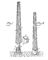
- a poleshaped supporting member 1 is shown as a conical tubular member, having the larger end portion located adjacent to a base structure 2.
- the tubular member 1 has a surrounding surface with a mainly corrugated shape, but also other shapes can obviously be used.
- An attachment member 3 extends from the base structure 2 in direction towards the tubular member 1, having a conical shape substantially corresponding to the adjacent end portion of the tubular member 1.
- Fig. 1 also shows how an electric feed cable 4 extends up through the base structure 2 and the attachment member 3, and how said feed cable 4 is terminated by means of a first electric connection member 5.
- a second electric connection member 6 is attached to a cable 7, extending surrounded by the tubular member 1, intended to be connected at the opposed and not shown end portion to a light fitting: suspended by the tubular member.
- a fuse box 8 is also shown adjacently located to the connection member 5, 6, preferably arranged to connect the feed cable 4 with the first connection member 5 in a not shown way. It should be mentioned, that the first connection member 5 and the fuse box 8 advantageously are attached against, or recessed below, the upper plane of the attachment member 3, even though same have been shown located above said plane. With regard to this embodiment, the attachment member 3 should preferably not extend more than a short distance above the ground level, preferably not exceeding a few decimeter.
- the base structure 2 When used, the base structure 2 is first attached in a conventional way, e.g. by concreting, and the feed cable 4 is attached to the first connection member 5.
- the poleshaped supporting member 1 is preferably joined to intended light fitting before attachment to the base structure 2, which fitting is connected to the second connection member 6 by means of the cable 7 enclosed within the poleshaped member 1.
- the poleshaped member 1 is located with the larger end portion adjacent to the base structure 2, and the first and the second connection member, 5 and 6 respectively, are plugged together. Electrical connection has thus been established, and the poleshaped supporting member is thereafter raised to a substantially vertical position, and then placed over the base structure 2, the attachment member 3 being located embraced by the poleshaped member 1.
- a locking member is utilized, as a complete unit denominated 9, shown in Fig. 2.
- Said locking member 9, which before placing the poleshaped member 1 against the base structure 2 is located surrounding the poleshaped member 1 at a distance from the large end portion of said member, comprises of a tubular member, having at least one periphreal portion arranged as a wedgeshaped part 10, formed by an embossed portion, joined to the remaining tubular member 9 by means of towards each other inclined portions.
- Said wedgeshaped part 10 thus forms a resilient expandable member together with the tubular member 9, thereby facilitating diametrical expansion of the tubular member 9.
- a through hole 11 is taken up in the outer portion of the wedgeshaped part 10, intended to facilitate attachment of a tool.
- the locking member 9 is slided towards the base structure 2, e.g. by impact force applied against the upper edge portion of the wedgeshaped part 10, whereby the locking member 9 takes up the position shown in Fig. 2, i.e. located adjacent to the base structure 2. Since the internal diameter of the locking member 9 is chosen smaller than the external diameter of the larger end portion of the poleshaped member 1, the last mentioned end portion is pressed against the attachment member 3, whereby the poleshaped member 1 is locked in relation to the base structure 2.
- a special purpose tool including a hook-shaped part which can be attached to the hole 11 in the wedgeshaped part 10.
- the hook-shaped part is arranged to move away from the base structure 2, and thus move the locking member 9 to a location in which same no longer applies a pressure against the poleshaped member 1 in direction towards the attachment member 3. Since the locking member 9 in applied position usually is arranged located below the ground surface, the risk for unauthorized influence against same is small, and such influence also requires access to a specifically designed tool.
- Fig. 1 and 2 The embodiment shown in Fig. 1 and 2 is primarily intended for applications in which the upper plane of the attachment member 3 must be located above the ground surface, in order to obtain security against penetration of ground water or rain water above said plane.
- Figs. 3 and 4 An example of an embodiment for such applications is shown in Figs. 3 and 4.
- the base structure 2 has been arranged with a number of drainage holes 12, 12' in the plane from which the attachment member 3 extends (only shown in Fig. 3). From said plane of the base structure 2, a tubular member 13 also extends upwardly, against the upper plane of which a sealing collar 14, e.g. of rubber, synthetic rubber, synthetic plastic or similar, is arranged to take up contact.
- a sealing collar 14 e.g. of rubber, synthetic rubber, synthetic plastic or similar
- the attachment member 3 is only intended to extend a small distance above the ground surface, comparable to the tyre height for conventional cars tyres, i.e. usually not exceeding 300 mm.
- the vehicle will only suffer minor damage, since the low height of the attachment member 3 will only cause the tyre of the wheel in question to be twisted off or damaged.
- the poleshaped member 1 is manufactured from fairly thin sheet metal, also a direct collision will result in extremely restricted damage to the vehicle, since the poleshaped member is bent down.
- the design is extremely suitable. In this case, the poleshaped member 1 disengages from the base structure 2, and falls down behind the vehicle causing the disengagement.
- the conditions relating to collision with vehicles are even more favourable. Since the entire attachment member 3 is located below the ground surface, damage imposed on a colliding vehicle is restricted to a minimum. In low speed collisions, the poleshaped member 1 is bent down, and it may possibly disengage from the attachment member 3. When collisions occur in high speed, the poleshaped member 1 is removed, and falls down without causing any actual damage to the colliding vehicle.
- poleshaped members 1 are electrically connected by means of a plug/jack connection, replacement of damaged members can be performed extremely rapid and simple.
- Existing connection in the attachment member 3 of the base structure 2 can basically always be regarded as undamaged, and a new poleshaped member can thus simply be electrically connected and installed in previously described fashion.
- poleshaped member 1 it may be desirable to strengthen the poleshaped member 1, e.g. when same is used to suspend a fitting located in a side relationship to the member 1. Strengthening can easily be accomplished to desired extent, by use of one or a number of conical tubular members, corresponding to the poleshaped member 1, which are slided into said last member 1.
- the length of such insertable elements can be choosen as desired, but they are preferably arranged in successively falling lengths in relation to the poleshaped member 1, and extending from the larger end portion of said member 1.
- the locking member 9 can thus be arranged in a number of other ways, e.g. as one or a number of clamping straps, which can be arranged surrounding the portion of the poleshaped member 1 embracing the attachment member 3.
Abstract
Description
- The present invention relates to a poleshaped supporting member, and a base structure for attachment of same, said supporting member preferably being arranged to support street light assemblies, illuminated road signs or other electrical equipment.
- Previously known types of poleshaped supporting members can basically be divided into three categories, namely solid members, tubular members and members having a frameork construction. With regard to both solid members and members having a framework construction, a separate and external connection box must be used to accomplish electrical connection to an electric feed cable extending below the ground level, and said connection box also includes associated electrical fuses. Furthermore, the cable joining the connection box and the electrical equipment suspended by the member is substantially totally unprotected. In order to receive protection for the last mentioned cable, and in orderto avoid use of externally located connection boxes, tubular supporting members have previously been used, having an aperture located adjacent to the ground level, arranged with a detachably mounted lid. Terminal block and fuse holders can thus be arranged covered by said lid. In view of the fact that the aperture located adjacent to the ground level considerably reduces the physical properties of the tubular supporting member, a relatively large wall thickness has been required, resulting in large weight and high manufacturing cost for the member, and the members also cause considerable damage in collisions with vehicles. Certain proposed "collision friendly" members are previously known, e.g., having frac- tural impressions added during manufacture, intended to make the member break if same is involved in a collision with a vehicle. Also this last mentioned type is expensive to manufacture, and installation costs are also high.
- US-A-1 870 770 describes a poleshaped tubular supporting member, comprising a plurality of tubular telescoping members, each member having a conically reduced cross-section in direction from the ground plane, the upper portion of each member having a conicity and external shape substantially corresponding to the lower portion of the uppermost member. At least one clamping member surrounding the upper member is arranged to press the lower portion of said upper member into a frictional contact position against the lower member.
- The object of the present invention is to disclose a poleshaped supporting member, which completely meets the requirements fulfilled by the above discussed previously known tubular supporting members, but which also prevents unauthorized manipulation with the terminal block and the fuse holder which are located surrounded by the member. The member further facilitates extremely simple and rapid installation, as well as electrical connection. Finally, extremely high requirements relating to safety against damage in a collision with a vehicle are also catered for, and after such an incident, a damaged member can be replaced by a new member rapidly and at a low cost.
- The poleshaped supporting member according to the present invention, and the base structure for attachment of same, comprises of a poleshaped member (1) having a tubular and conically reduced cross-section in direction from the ground plane, the associated base structure (2) including an attachment member (3) extending in direction towards the poleshaped member (1) having a conicity and external shape substantially corresponding to surrounding portion of the poleshaped member (1), at least one clamping member (9) surrounding the poleshaped member (1) arranged to press the portion of the poleshaped member (1) surrounding the attachment member (3) into a frictional contact position against the attachment member (3), said members being mainly characterised in that a first electrical connection member (5) is arranged adjacent to the upper plane of the attachment member (3), joined to an electric feed cable (4), preferably via an intermediately located fuse means (8), a second electrical connecting member being arranged adjacent to the larger end portion of the poleshaped member (1), joined to a cable (7) surrounded by said member (1), said connecting members (5, 6) being arranged interconnectableto cause voltage feed to an electric fitting suspended directly or indirectly by the poleshaped member (1), and that the clamping member (9) comprises of at least one substantially tubular member (9), including at least one longitudinally extending wedgeshaped part (10) formed as an embossed part, being joined to the remaining tubular member (9) by means of towards each other inclined portions, said last mentioned member (9) having an internal diameter smaller than the external diameter of the poleshaped member (1) at the portion intended to embrace the attachment member (3).
- Two basic examples of embodiments according to the present invention are more fully described with reference to the accompanying drawings, in which:-
- Fig. 1 shows a perspective view of a first embodiment of a poleshaped supporting member and associated base structure according to the invention, located separated from each other;
- Fig. 2 shows the poleshaped member and associated base structure as shown in Fig. 1 joined together, and with a detailed view of an associated clamping member shown in an adjacent position;
- Fig. 3 shows a perspective view of a second embodiment according to the invention, with a poleshaped supporting member and the base structure located separated from each other, and
- Fig. 4 shows the poleshaped supporting member and associated base structure of Fig. 3 joined together, and two associated parts shown as adjacently located detailed views.
- With reference to the embodiment shown in Figs. 1 and 2, a poleshaped supporting
member 1 is shown as a conical tubular member, having the larger end portion located adjacent to a base structure 2. Thetubular member 1 has a surrounding surface with a mainly corrugated shape, but also other shapes can obviously be used. Anattachment member 3 extends from the base structure 2 in direction towards thetubular member 1, having a conical shape substantially corresponding to the adjacent end portion of thetubular member 1. Fig. 1 also shows how an electric feed cable 4 extends up through the base structure 2 and theattachment member 3, and how said feed cable 4 is terminated by means of a firstelectric connection member 5. A secondelectric connection member 6 is attached to acable 7, extending surrounded by thetubular member 1, intended to be connected at the opposed and not shown end portion to a light fitting: suspended by the tubular member. Afuse box 8 is also shown adjacently located to theconnection member first connection member 5 in a not shown way. It should be mentioned, that thefirst connection member 5 and thefuse box 8 advantageously are attached against, or recessed below, the upper plane of theattachment member 3, even though same have been shown located above said plane. With regard to this embodiment, theattachment member 3 should preferably not extend more than a short distance above the ground level, preferably not exceeding a few decimeter. - When used, the base structure 2 is first attached in a conventional way, e.g. by concreting, and the feed cable 4 is attached to the
first connection member 5. The poleshaped supportingmember 1 is preferably joined to intended light fitting before attachment to the base structure 2, which fitting is connected to thesecond connection member 6 by means of thecable 7 enclosed within thepoleshaped member 1. Thepoleshaped member 1 is located with the larger end portion adjacent to the base structure 2, and the first and the second connection member, 5 and 6 respectively, are plugged together. Electrical connection has thus been established, and the poleshaped supporting member is thereafter raised to a substantially vertical position, and then placed over the base structure 2, theattachment member 3 being located embraced by thepoleshaped member 1. - In order to lock the
poleshaped member 1 against the base structure 2, a locking member is utilized, as a complete unit denominated 9, shown in Fig. 2. Said lockingmember 9, which before placing thepoleshaped member 1 against the base structure 2 is located surrounding thepoleshaped member 1 at a distance from the large end portion of said member, comprises of a tubular member, having at least one periphreal portion arranged as awedgeshaped part 10, formed by an embossed portion, joined to the remainingtubular member 9 by means of towards each other inclined portions. Saidwedgeshaped part 10 thus forms a resilient expandable member together with thetubular member 9, thereby facilitating diametrical expansion of thetubular member 9. Furthermore, athrough hole 11 is taken up in the outer portion of thewedgeshaped part 10, intended to facilitate attachment of a tool. - When the
poleshaped member 1 has been located embracing theattachment member 3, thelocking member 9 is slided towards the base structure 2, e.g. by impact force applied against the upper edge portion of thewedgeshaped part 10, whereby thelocking member 9 takes up the position shown in Fig. 2, i.e. located adjacent to the base structure 2. Since the internal diameter of thelocking member 9 is chosen smaller than the external diameter of the larger end portion of thepoleshaped member 1, the last mentioned end portion is pressed against theattachment member 3, whereby thepoleshaped member 1 is locked in relation to the base structure 2. - In order to remove the above described
locking member 9, e.g. for maintenance operations, a special purpose tool is used, including a hook-shaped part which can be attached to thehole 11 in thewedgeshaped part 10. By application of pressure against said tool, the hook-shaped part is arranged to move away from the base structure 2, and thus move thelocking member 9 to a location in which same no longer applies a pressure against thepoleshaped member 1 in direction towards theattachment member 3. Since thelocking member 9 in applied position usually is arranged located below the ground surface, the risk for unauthorized influence against same is small, and such influence also requires access to a specifically designed tool. - The embodiment shown in Fig. 1 and 2 is primarily intended for applications in which the upper plane of the
attachment member 3 must be located above the ground surface, in order to obtain security against penetration of ground water or rain water above said plane. However, there are a large number of applications for which such precautions are unnecessary, and an example of an embodiment for such applications is shown in Figs. 3 and 4. - In these figures, the same method of attachment is used as described with reference to the first embodiment, but in order to remove rain water and similar, the base structure 2 has been arranged with a number of
drainage holes 12, 12' in the plane from which theattachment member 3 extends (only shown in Fig. 3). From said plane of the base structure 2, atubular member 13 also extends upwardly, against the upper plane of which a sealingcollar 14, e.g. of rubber, synthetic rubber, synthetic plastic or similar, is arranged to take up contact. - In the embodiment shown in Figs 1 and 2, the
attachment member 3 is only intended to extend a small distance above the ground surface, comparable to the tyre height for conventional cars tyres, i.e. usually not exceeding 300 mm. In a possible collision with a vehicle, and if said vehicle should hit the poleshaped member and associated base structure with one of the vehicle wheels, the vehicle will only suffer minor damage, since the low height of theattachment member 3 will only cause the tyre of the wheel in question to be twisted off or damaged. Since thepoleshaped member 1 is manufactured from fairly thin sheet metal, also a direct collision will result in extremely restricted damage to the vehicle, since the poleshaped member is bent down. Also with regard to collision in high speed, when there is a risk that the poleshaped member falls down onto a colliding vehicle, the design is extremely suitable. In this case, thepoleshaped member 1 disengages from the base structure 2, and falls down behind the vehicle causing the disengagement. - With regard to the embodiment shown in Figs. 3 and 4, the conditions relating to collision with vehicles are even more favourable. Since the
entire attachment member 3 is located below the ground surface, damage imposed on a colliding vehicle is restricted to a minimum. In low speed collisions, thepoleshaped member 1 is bent down, and it may possibly disengage from theattachment member 3. When collisions occur in high speed, thepoleshaped member 1 is removed, and falls down without causing any actual damage to the colliding vehicle. - Since the
poleshaped members 1 are electrically connected by means of a plug/jack connection, replacement of damaged members can be performed extremely rapid and simple. Existing connection in theattachment member 3 of the base structure 2 can basically always be regarded as undamaged, and a new poleshaped member can thus simply be electrically connected and installed in previously described fashion. - Existing electrical connections and associated fuses are also well protected against influence from unauthorized persons, as compared to previously known types where only attachment screws for a protective lid must be removed. When replacing a fuse, or similar operation, authorized persons having the previously mentioned demounting tool can easily separate the
poleshaped member 1 from the base structure 2, and due to the low weight of thepoleshaped member 1, same can easily be lifted during such an operation. - For certain applications, it may be desirable to strengthen the
poleshaped member 1, e.g. when same is used to suspend a fitting located in a side relationship to themember 1. Strengthening can easily be accomplished to desired extent, by use of one or a number of conical tubular members, corresponding to thepoleshaped member 1, which are slided into saidlast member 1. The length of such insertable elements can be choosen as desired, but they are preferably arranged in successively falling lengths in relation to thepoleshaped member 1, and extending from the larger end portion of saidmember 1. - The embodiments shown and described are only intended to serve as examples of embodiments within the scope of the inventive thought and the following claims, and may obviously be further modified for various applications. For example, the
locking member 9 can thus be arranged in a number of other ways, e.g. as one or a number of clamping straps, which can be arranged surrounding the portion of thepoleshaped member 1 embracing theattachment member 3.
Claims (7)
Priority Applications (1)
| Application Number | Priority Date | Filing Date | Title |
|---|---|---|---|
| AT83903605T ATE47456T1 (en) | 1983-11-01 | 1983-11-01 | POSTAL BEAM AND FOOT FOR ITS FIXATION. |
Applications Claiming Priority (1)
| Application Number | Priority Date | Filing Date | Title |
|---|---|---|---|
| PCT/SE1983/000376 WO1985001977A1 (en) | 1983-11-01 | 1983-11-01 | Poleshaped supporting member, and base structure for attachment of same |
Publications (2)
| Publication Number | Publication Date |
|---|---|
| EP0189395A1 EP0189395A1 (en) | 1986-08-06 |
| EP0189395B1 true EP0189395B1 (en) | 1989-10-18 |
Family
ID=20349757
Family Applications (1)
| Application Number | Title | Priority Date | Filing Date |
|---|---|---|---|
| EP83903605A Expired EP0189395B1 (en) | 1983-11-01 | 1983-11-01 | Poleshaped supporting member, and base structure for attachment of same |
Country Status (10)
| Country | Link |
|---|---|
| US (1) | US4617768A (en) |
| EP (1) | EP0189395B1 (en) |
| JP (1) | JPS61500269A (en) |
| AT (1) | ATE47456T1 (en) |
| CA (1) | CA1230727A (en) |
| DE (1) | DE3380741D1 (en) |
| IN (1) | IN161288B (en) |
| NZ (1) | NZ210052A (en) |
| WO (1) | WO1985001977A1 (en) |
| ZA (1) | ZA848450B (en) |
Cited By (3)
| Publication number | Priority date | Publication date | Assignee | Title |
|---|---|---|---|---|
| AU2012207010B2 (en) * | 2012-07-09 | 2015-11-05 | Delnorth Pty. Ltd. | A Frangible Pole with Wear Shoe |
| AU2013201109B2 (en) * | 2013-02-26 | 2016-05-19 | Delnorth Pty. Ltd. | A Frangible Pole Assembly |
| CN112267740A (en) * | 2020-01-13 | 2021-01-26 | 浙江晶日科技股份有限公司 | Multifunctional rod |
Families Citing this family (47)
| Publication number | Priority date | Publication date | Assignee | Title |
|---|---|---|---|---|
| US4999966A (en) * | 1988-07-19 | 1991-03-19 | Houston Industries Incorporated | Method of forming an-before "immured" |
| US5050356A (en) * | 1988-07-19 | 1991-09-24 | Houston Industries Incorporated | Immured foundation |
| US5029054A (en) * | 1988-11-10 | 1991-07-02 | Adb-Alnaco, Inc. | Light base and transformer housing |
| DE69108948T2 (en) * | 1990-01-31 | 1995-11-23 | Musco Corp | Means and methods for the permanent erection of a building structure. |
| US6340790B1 (en) | 1990-01-31 | 2002-01-22 | Musco Corporation | Means and method for integrated lighting fixture supports and components |
| US5600537A (en) * | 1991-02-06 | 1997-02-04 | Musco Corporation | Ballast box for integrated location of ballasts and electrical connections |
| US5335160A (en) * | 1993-07-13 | 1994-08-02 | Duraline | Mast-type outdoor lighting system |
| US5481846A (en) * | 1995-03-27 | 1996-01-09 | Valmont Industries, Inc. | Support pole having a bell-shaped lower end |
| SE9702655D0 (en) * | 1997-07-09 | 1997-07-09 | Lars Svensson | Ways to make post and post made according to the method |
| FI104132B (en) * | 1997-09-08 | 1999-11-15 | Jerol Ind Ab | Post |
| US5964444A (en) * | 1997-10-31 | 1999-10-12 | Guertler; James J. | Traffic light assembly |
| US6250596B1 (en) | 1998-05-13 | 2001-06-26 | Musco Corporation | Spacer between pole and cross-arm |
| USD411096S (en) * | 1998-05-13 | 1999-06-15 | Musco Corporation | Spacer between pole and cross-arm |
| US6309143B1 (en) * | 1998-05-27 | 2001-10-30 | Stanley Merjan | Composite pile with tapering lower portion and method for driving pile into granular soil |
| US6303857B1 (en) | 1998-10-19 | 2001-10-16 | D.O.T. Connectors, Inc. | Mast lighting system |
| US6872883B2 (en) * | 1998-10-19 | 2005-03-29 | Thomas A. Ginsburg | Mast lighting system |
| US6464196B1 (en) * | 1998-12-21 | 2002-10-15 | Mucso Corporation | Apparatus and method for a temporary spread footing |
| US6705058B1 (en) | 1999-02-12 | 2004-03-16 | Newmark International Inc. | Multiple-part pole |
| US6327833B1 (en) | 1999-08-27 | 2001-12-11 | Newmark International, Inc | Hollow pole with hollow stub foundation |
| FR2799482B1 (en) * | 1999-10-12 | 2001-11-30 | Maurice Guitton | PROTECTIVE POST OR TERMINAL, AND BARRIER INCLUDING APPLICATION |
| US6240689B1 (en) | 2000-02-22 | 2001-06-05 | Genlyte Thomas Group Llc | Utility standard |
| US6543911B1 (en) * | 2000-05-08 | 2003-04-08 | Farlight Llc | Highly efficient luminaire having optical transformer providing precalculated angular intensity distribution and method therefore |
| US8360615B2 (en) * | 2000-05-08 | 2013-01-29 | Farlight, Llc | LED light module for omnidirectional luminaire |
| US6692142B1 (en) | 2000-08-04 | 2004-02-17 | Musco Corporation | Apparatus, method, and system of a moveable lighting |
| US6467233B1 (en) * | 2000-11-09 | 2002-10-22 | Beaird Industries, Inc | Wind tower |
| US7083315B2 (en) * | 2001-03-26 | 2006-08-01 | Siemens Airfield Solutions | Elevated airfield runway and taxiway edge-lights utilizing light emitting diodes |
| FR2843417B1 (en) * | 2002-08-06 | 2004-09-10 | Daniel Saussez | HELICOPTER ANTI-LANDING DEVICE |
| US7490964B2 (en) | 2002-10-09 | 2009-02-17 | Genlyte Thomas Group Llc | Modular pole system for a light fixture |
| AU2002952248A0 (en) * | 2002-10-25 | 2002-11-07 | Goodcart Pty Ltd | Multi purpose pole |
| DE10338347A1 (en) * | 2003-08-21 | 2005-03-17 | Christa Reiners | Lighting pole made of metal |
| CA2469264C (en) * | 2004-05-17 | 2011-04-12 | Richard Bergman | Post anchoring device |
| US7762041B1 (en) | 2004-11-03 | 2010-07-27 | Valmont Newmark, Inc. | Hybrid metal pole |
| WO2006097108A1 (en) | 2005-03-16 | 2006-09-21 | Densit A/S | Tower foundation system and method for providing such system |
| US7363751B2 (en) | 2005-09-06 | 2008-04-29 | Shakespeare Composite Structures, Llc | Wound-in tenon/wound-in tenon collar for attachment of luminaire |
| US20070090653A1 (en) * | 2005-10-04 | 2007-04-26 | Martelon David R | Hover Installed Renewable Energy Tower |
| US7492064B1 (en) | 2006-01-10 | 2009-02-17 | Signal Engineering Company-South | Luminaire safety system |
| WO2009009425A2 (en) * | 2007-07-09 | 2009-01-15 | Scott Ryan | Support pole structure and method of manufacture |
| NO333320B1 (en) * | 2008-03-11 | 2013-05-06 | Juralco As | Compliant mast carrying devices requiring electric power supply. |
| NL1035407C2 (en) * | 2008-05-09 | 2009-11-11 | Martens Prefab Beton B V | Mast for use as electricity pylon, has foot affixed to ground by rolling resistance connection, where mast is divided into lower segment and upper segment on top of lower segment |
| US8061666B1 (en) | 2008-08-05 | 2011-11-22 | Philips Electronics Ltd | Adapter assembly for pole luminaire |
| EP2668063B1 (en) * | 2011-01-28 | 2017-01-18 | Unimi Solutions AB | Foundation system for charging poles |
| US8684551B2 (en) | 2011-10-05 | 2014-04-01 | Abdulreidha A. Alsaffar | Lighting assembly in the form of a palm tree |
| FR3040718B1 (en) * | 2015-09-09 | 2017-08-11 | Christian Liaud | ACCOMODATION COMPLEX PERCHE DE LOISIR |
| US10294687B2 (en) | 2016-11-08 | 2019-05-21 | Valmont West Coast Engineering Ltd. | System for coupling together segments of a utility pole, and a utility pole assembly comprising the same |
| KR102525081B1 (en) | 2018-07-26 | 2023-04-21 | 무스코 코포레이션 | Apparatus and method for design and installation of a customizable football mini-pitch system |
| US11457715B2 (en) * | 2020-03-13 | 2022-10-04 | The Gillette Company Llc | Stand for a shaving razor |
| USD1006155S1 (en) * | 2021-07-01 | 2023-11-28 | P&P Imports LLC | Basketball goal assembly |
Family Cites Families (13)
| Publication number | Priority date | Publication date | Assignee | Title |
|---|---|---|---|---|
| CA688576A (en) * | 1964-06-09 | C. Walker George | Sectional tubular pole | |
| US1870770A (en) * | 1927-04-02 | 1932-08-09 | Taper Tube Pole Co | Steel pole |
| AT151477B (en) * | 1932-12-15 | 1937-11-10 | Josef Ing Pfistershammer | Conical, thin-walled sheet-metal tube pieces of assembled tubular mast, in particular overhead line mast. |
| US2016011A (en) * | 1933-08-18 | 1935-10-01 | Kent Arnold Frederick | Wireless aerial |
| US2945659A (en) * | 1957-10-10 | 1960-07-19 | Mcdonald Earl | Parking meter post construction |
| US3364635A (en) * | 1966-01-26 | 1968-01-23 | Kenneth F. Guggemos | Recessed hinged base standard |
| FR2031890A5 (en) * | 1969-02-12 | 1970-11-20 | Ehrhard Roger | |
| FR2044425A5 (en) * | 1969-05-20 | 1971-02-19 | Sermeto | |
| US3671738A (en) * | 1971-01-13 | 1972-06-20 | Robert W Beachley | Lighting standard or pole with doubly hinged base |
| US3974372A (en) * | 1974-10-30 | 1976-08-10 | The City Of Portland | Ornamental lighting standard |
| DE2708664A1 (en) * | 1976-03-01 | 1977-09-15 | Michel Leclerc | Overhead cable support pylon - has assembled repairable free part and ground sunken plinth component |
| DE3032575A1 (en) * | 1980-08-29 | 1982-04-08 | G.A. Pfleiderer GmbH & Co KG, 8430 Neumarkt | METHOD FOR ATTACHING A FOOTPLATE TO A PAST PRODUCED BY SPIN, AND FOOTPLATE FOR CARRYING OUT THE METHOD |
| EP0067903A3 (en) * | 1981-06-24 | 1983-07-27 | Vulkan Werk für Industrie- und Aussenbeleuchtung GmbH | Tubular mast constituted of stacked elements |
-
1983
- 1983-11-01 DE DE8383903605T patent/DE3380741D1/en not_active Expired
- 1983-11-01 EP EP83903605A patent/EP0189395B1/en not_active Expired
- 1983-11-01 JP JP83503572A patent/JPS61500269A/en active Pending
- 1983-11-01 WO PCT/SE1983/000376 patent/WO1985001977A1/en active IP Right Grant
- 1983-11-01 AT AT83903605T patent/ATE47456T1/en not_active IP Right Cessation
- 1983-11-01 US US06/755,334 patent/US4617768A/en not_active Expired - Lifetime
-
1984
- 1984-10-25 IN IN824/DEL/84A patent/IN161288B/en unknown
- 1984-10-30 CA CA000466608A patent/CA1230727A/en not_active Expired
- 1984-10-30 ZA ZA848450A patent/ZA848450B/en unknown
- 1984-10-31 NZ NZ210052A patent/NZ210052A/en unknown
Cited By (4)
| Publication number | Priority date | Publication date | Assignee | Title |
|---|---|---|---|---|
| AU2012207010B2 (en) * | 2012-07-09 | 2015-11-05 | Delnorth Pty. Ltd. | A Frangible Pole with Wear Shoe |
| AU2013201109B2 (en) * | 2013-02-26 | 2016-05-19 | Delnorth Pty. Ltd. | A Frangible Pole Assembly |
| CN112267740A (en) * | 2020-01-13 | 2021-01-26 | 浙江晶日科技股份有限公司 | Multifunctional rod |
| CN112267740B (en) * | 2020-01-13 | 2022-06-03 | 浙江晶日科技股份有限公司 | Multifunctional rod |
Also Published As
| Publication number | Publication date |
|---|---|
| CA1230727A (en) | 1987-12-29 |
| EP0189395A1 (en) | 1986-08-06 |
| NZ210052A (en) | 1988-08-30 |
| US4617768A (en) | 1986-10-21 |
| DE3380741D1 (en) | 1989-11-23 |
| JPS61500269A (en) | 1986-02-20 |
| WO1985001977A1 (en) | 1985-05-09 |
| IN161288B (en) | 1987-11-07 |
| ATE47456T1 (en) | 1989-11-15 |
| ZA848450B (en) | 1985-06-26 |
Similar Documents
| Publication | Publication Date | Title |
|---|---|---|
| EP0189395B1 (en) | Poleshaped supporting member, and base structure for attachment of same | |
| US6308927B1 (en) | Breakaway sign post connector | |
| US3846030A (en) | Post | |
| US5535555A (en) | Breakaway post coupling | |
| US5547310A (en) | Barrier construction for removably closing road passages | |
| KR101671492B1 (en) | Delineator post | |
| US6959902B2 (en) | Breakaway signpost connector | |
| US20110248143A1 (en) | Breakaway Device for Posts | |
| US7793910B2 (en) | Surface-mounted post base | |
| GB2228513A (en) | Resilient collar for surrounding a manhole support, sewer inlet etc. during street repairs. | |
| KR200340615Y1 (en) | Extending cable hanger | |
| KR100889869B1 (en) | Manhole for distributing electric wires | |
| US20020098038A1 (en) | Replaceable, reusable insert that protects vehicular traffic from recessed roadway structures | |
| CN218661379U (en) | Controller protection architecture for electric automobile | |
| CN218521848U (en) | Well lid convenient to installation is dismantled | |
| CN217975712U (en) | Building engineering protects rail with remind function | |
| CN212714720U (en) | 10kV power equipment anti-collision warning pile suitable for road section without street lamp | |
| CN214506501U (en) | Prevent cable protection mechanism that rolls | |
| CN210395446U (en) | Temporary protection device for maintenance of inspection well | |
| KR200294929Y1 (en) | Protection cover for traffic safety installation | |
| KR102489426B1 (en) | Support of Displaying Boundary of Road | |
| KR200430695Y1 (en) | case for connect electric cables | |
| CN209538068U (en) | A kind of reflective column facilitating installation | |
| CN216193746U (en) | Multipurpose gangplank | |
| CN214737575U (en) | Maintenance vehicle capable of obliquely placing traffic cones |
Legal Events
| Date | Code | Title | Description |
|---|---|---|---|
| PUAI | Public reference made under article 153(3) epc to a published international application that has entered the european phase |
Free format text: ORIGINAL CODE: 0009012 |
|
| AK | Designated contracting states |
Kind code of ref document: A1 Designated state(s): AT BE CH DE FR GB LI NL SE |
|
| 17P | Request for examination filed |
Effective date: 19860627 |
|
| 17Q | First examination report despatched |
Effective date: 19871006 |
|
| GRAA | (expected) grant |
Free format text: ORIGINAL CODE: 0009210 |
|
| AK | Designated contracting states |
Kind code of ref document: B1 Designated state(s): AT BE CH DE FR GB LI NL SE |
|
| PG25 | Lapsed in a contracting state [announced via postgrant information from national office to epo] |
Ref country code: SE Effective date: 19891018 Ref country code: NL Effective date: 19891018 Ref country code: AT Effective date: 19891018 |
|
| REF | Corresponds to: |
Ref document number: 47456 Country of ref document: AT Date of ref document: 19891115 Kind code of ref document: T |
|
| ET | Fr: translation filed | ||
| REF | Corresponds to: |
Ref document number: 3380741 Country of ref document: DE Date of ref document: 19891123 |
|
| PG25 | Lapsed in a contracting state [announced via postgrant information from national office to epo] |
Ref country code: LI Free format text: LAPSE BECAUSE OF NON-PAYMENT OF DUE FEES Effective date: 19891130 Ref country code: CH Free format text: LAPSE BECAUSE OF NON-PAYMENT OF DUE FEES Effective date: 19891130 |
|
| NLV1 | Nl: lapsed or annulled due to failure to fulfill the requirements of art. 29p and 29m of the patents act | ||
| PLBE | No opposition filed within time limit |
Free format text: ORIGINAL CODE: 0009261 |
|
| STAA | Information on the status of an ep patent application or granted ep patent |
Free format text: STATUS: NO OPPOSITION FILED WITHIN TIME LIMIT |
|
| 26N | No opposition filed | ||
| REG | Reference to a national code |
Ref country code: CH Ref legal event code: PL |
|
| PGFP | Annual fee paid to national office [announced via postgrant information from national office to epo] |
Ref country code: GB Payment date: 19911030 Year of fee payment: 9 |
|
| PGFP | Annual fee paid to national office [announced via postgrant information from national office to epo] |
Ref country code: BE Payment date: 19911129 Year of fee payment: 9 |
|
| PGFP | Annual fee paid to national office [announced via postgrant information from national office to epo] |
Ref country code: DE Payment date: 19911203 Year of fee payment: 9 |
|
| PG25 | Lapsed in a contracting state [announced via postgrant information from national office to epo] |
Ref country code: GB Effective date: 19921101 |
|
| PG25 | Lapsed in a contracting state [announced via postgrant information from national office to epo] |
Ref country code: BE Effective date: 19921130 |
|
| PGFP | Annual fee paid to national office [announced via postgrant information from national office to epo] |
Ref country code: FR Payment date: 19921130 Year of fee payment: 10 |
|
| BERE | Be: lapsed |
Owner name: GEBELIUS SVEN RUNO VILHELM Effective date: 19921130 |
|
| GBPC | Gb: european patent ceased through non-payment of renewal fee |
Effective date: 19921101 |
|
| PG25 | Lapsed in a contracting state [announced via postgrant information from national office to epo] |
Ref country code: DE Effective date: 19930803 |
|
| PG25 | Lapsed in a contracting state [announced via postgrant information from national office to epo] |
Ref country code: FR Effective date: 19940729 |
|
| REG | Reference to a national code |
Ref country code: FR Ref legal event code: ST |