EP0189491A1 - Device for dosed simultaneous infusing solutions - Google Patents
Device for dosed simultaneous infusing solutions Download PDFInfo
- Publication number
- EP0189491A1 EP0189491A1 EP85100793A EP85100793A EP0189491A1 EP 0189491 A1 EP0189491 A1 EP 0189491A1 EP 85100793 A EP85100793 A EP 85100793A EP 85100793 A EP85100793 A EP 85100793A EP 0189491 A1 EP0189491 A1 EP 0189491A1
- Authority
- EP
- European Patent Office
- Prior art keywords
- infusion
- drop
- drops
- control unit
- solutions
- Prior art date
- Legal status (The legal status is an assumption and is not a legal conclusion. Google has not performed a legal analysis and makes no representation as to the accuracy of the status listed.)
- Withdrawn
Links
Images


Classifications
-
- A—HUMAN NECESSITIES
- A61—MEDICAL OR VETERINARY SCIENCE; HYGIENE
- A61M—DEVICES FOR INTRODUCING MEDIA INTO, OR ONTO, THE BODY; DEVICES FOR TRANSDUCING BODY MEDIA OR FOR TAKING MEDIA FROM THE BODY; DEVICES FOR PRODUCING OR ENDING SLEEP OR STUPOR
- A61M5/00—Devices for bringing media into the body in a subcutaneous, intra-vascular or intramuscular way; Accessories therefor, e.g. filling or cleaning devices, arm-rests
- A61M5/14—Infusion devices, e.g. infusing by gravity; Blood infusion; Accessories therefor
- A61M5/168—Means for controlling media flow to the body or for metering media to the body, e.g. drip meters, counters ; Monitoring media flow to the body
- A61M5/16804—Flow controllers
- A61M5/16827—Flow controllers controlling delivery of multiple fluids, e.g. sequencing, mixing or via separate flow-paths
-
- A—HUMAN NECESSITIES
- A61—MEDICAL OR VETERINARY SCIENCE; HYGIENE
- A61M—DEVICES FOR INTRODUCING MEDIA INTO, OR ONTO, THE BODY; DEVICES FOR TRANSDUCING BODY MEDIA OR FOR TAKING MEDIA FROM THE BODY; DEVICES FOR PRODUCING OR ENDING SLEEP OR STUPOR
- A61M5/00—Devices for bringing media into the body in a subcutaneous, intra-vascular or intramuscular way; Accessories therefor, e.g. filling or cleaning devices, arm-rests
- A61M5/14—Infusion devices, e.g. infusing by gravity; Blood infusion; Accessories therefor
- A61M5/168—Means for controlling media flow to the body or for metering media to the body, e.g. drip meters, counters ; Monitoring media flow to the body
- A61M5/16886—Means for controlling media flow to the body or for metering media to the body, e.g. drip meters, counters ; Monitoring media flow to the body for measuring fluid flow rate, i.e. flowmeters
- A61M5/1689—Drip counters
-
- A—HUMAN NECESSITIES
- A61—MEDICAL OR VETERINARY SCIENCE; HYGIENE
- A61M—DEVICES FOR INTRODUCING MEDIA INTO, OR ONTO, THE BODY; DEVICES FOR TRANSDUCING BODY MEDIA OR FOR TAKING MEDIA FROM THE BODY; DEVICES FOR PRODUCING OR ENDING SLEEP OR STUPOR
- A61M5/00—Devices for bringing media into the body in a subcutaneous, intra-vascular or intramuscular way; Accessories therefor, e.g. filling or cleaning devices, arm-rests
- A61M5/14—Infusion devices, e.g. infusing by gravity; Blood infusion; Accessories therefor
- A61M5/1407—Infusion of two or more substances
- A61M5/1408—Infusion of two or more substances in parallel, e.g. manifolds, sequencing valves
Definitions
- the invention relates to a device for the metered simultaneous infusion of solutions from several infusion containers, with drain lines leading from the containers to a collecting line and each containing a controlled valve, a pump provided in the collecting line with a selectable delivery volume and with a computer that controls the valves according to the infusion rates of the individual solutions set cyclically one after the other.
- an infusion device (DE- A 27 30 736) in which two infusion containers are connected to a common collecting line via drain lines.
- Each drain line contains a drip chamber with a drop counter: a control unit controls valves that are contained in the drain lines so that a valve is opened at predetermined times. If a single drop is then generated in the drip chamber, this is recognized by the associated drop detector and the valve is closed again. If one of the infusion containers has been emptied or if a flow obstacle occurs in the discharge line connected to this infusion container, the valve of this infusion container is closed and the solution is removed from the second infusion container in the same way.
- This known device is not used for the simultaneous infusion of several solutions, but rather monitors the infusion from a single infusion container and provides a replacement infusion container, from which the infusion solution is subsequently removed if the first system is emptied or fails.
- liquids with individually preselectable frequencies can be dispensed alternately from two liquid containers. Each time a predetermined number of drops from one container is reached, a control circuit switches over to the other container. The drop numbers must be preset immediately. It is not enough to simply preselect the infusion rates or the quantitative ratios.
- the invention is based on the object of developing a device of the type specified in the preamble of claim 1 to the extent that "the accuracy of the quantity dosing is increased both with regard to the dosing of the individual infusion solutions and also with regard to the total quantity, only the infusion rates having to be preselected on the device .
- the individual partial quantities of the infusion solutions are not supplied by time-dependent control of the valves, but rather quantity-dependent, the liquid quantity being measured by counting drops. While the measurement inaccuracies are greater than 25% in practice at time-controlled infusion rates, when using the device according to the invention the error is determined by the deviations in the drop size. These are less than 10%.
- the infusion rates to be selected by the doctor for the individual solutions are converted into proportional drop numbers in the control device. Each valve remains open until the number of drops assigned to this channel is reached. Then the valve is closed and the valve of the next channel is opened. Certain drop numbers are determined in each case and fed to the collecting line until a switchover takes place. The fixed minimum number of drops is the smallest unit of liquid quantity that is drawn to the manifold in an interval of the valve control leads. In this way, a reference base is obtained for the calculation of the drop numbers.
- a device which calculates drop numbers proportional to the infusion rates entered and, in the case of a non-integer drop number of a solution, rounds down to the lower integer, stores the resulting remainder and the rest added to the non-integer drop number of the same solution in the next cycle. In this way, the sum of the residual values accumulated over several cycles eventually becomes greater than 1, so that an additional drop is then generated for this channel. This means that for a particular solution, for example, eight drops are generated in four cycles and nine drops in every fifth cycle.
- the pump is preferably operated at a delivery rate corresponding to the sum of the infusion rates of the individual solutions.
- the pump runs at a constant flow rate and generates a negative pressure in the drip chambers, which means that liquid is sucked out of the relevant solution container and the formation of drops is promoted.
- Monitoring the total output by the. Pump is pumped can be done in that a flow meter is provided in the manifold, which triggers an alarm signal in the event of deviations from the intended delivery rate.
- This flow meter preferably consists of a drip chamber with a drop counter. Any deviations from the total flow rate calculated by the control device can also be used to change the control signals of the pump and / or the valves.
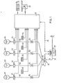
- FIG. 1 shows four infusion containers A1, A2, A3, A4 which are suspended with the opening facing downwards.
- An outlet line B1, B2, B3, B4 leads from each of the infusion containers to a common collection point 10.
- Each of the outlet lines B1 to B4 contains a drip chamber C1 to C4 with a drop counter, which will be explained below.
- a controllable valve D1 to D4 is provided in the drain line in the flow path behind the drip chamber.
- Each infusion container A1 to A4 is assigned a three-digit selector switch S1 to S4, on which the relevant infusion rate in ml / h can be set manually. All preselection switches S1 to S4 are connected to the control unit 11 so that the set infusion rates can be entered into the control unit.
- the control unit 11 also receives the signals from the drop detectors, which are assigned to the individual drip chambers C1 to C4. On the basis of this data, the control unit 11 controls the valves D1 to D4 in a cyclical sequence in such a way that one of the valves is opened while the other valves are closed.
- the collecting line 12 contains a volumetric pump 13, which is controlled by the control device 11 via a control line 14 and conveys the liquid contained in the collecting line 12 to the patient at the predetermined supply rate. Between the collecting point 10 and the pump 13 there is a flow meter 15 in the collecting line 12, which in the present case consists of a drip chamber 16 with a drop detector 17.
- the 2 shows the transmission device, the piercing mandrel 18 of which is pierced through the elastomer plug with which the infusion container A1 is closed.
- the Einsteqhdorn 18 has a liquid channel 19 and an air channel 20, which emerge at the front end near the tip.
- the liquid channel 19 leads into the drip chamber C1, which is connected at its lower end to the drain line B1.
- the drip chamber C1 consists of translucent material in the present case.
- the photo sensor 24 generates a signal each time a drop of liquid crosses the light barrier formed by the light source 23 and the photo sensor 24.
- other drop detectors can also be used, which use ultrasound, an electric field, a magnetic field or the like. or drop detectors that respond to pressure changes, e.g. Piezo converter. It is only important that each drop of liquid falling from the liquid line 19 into the drip chamber C1 triggers a signal which is further processed in the manner to be explained.
- the liquid channel 19 is so narrow that the liquid drops through it dropwise into the drip chamber C1.
- the drip chambers C2 to C4 are designed in the same way and provided with a piercing mandrel as the drip chamber C1 shown in FIG. 2.
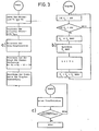
- the control unit 11 is, for example, a computer which is programmed according to the flow diagrams shown in FIG. 3.
- the feed rates V1 to V4 which have been set on the preselection switches S1 to S4, are read into the control unit 11 (FIG. 3a).
- the delivery rate V min which has the smallest value is then determined from the delivery rates V1 to V4.
- the drop numbers are calculated close to the formula
- i is the index number of the respective channel, i.e. a number from 1 to 4.
- the number of drops is multiplied by 100 so that the computer only has to process whole numbers (and no digits after the decimal point).
- the number 600 results from the fact that the minimum number of drops, which corresponds to the smallest delivery rate V min , has been set to 6 drops.
- the drop numbers for all four channels are determined using the formula given above.
- the total delivery rate W V 1 + V 2 + V 3 + V 4 is then determined in order to control the pump 13 at a delivery rate which corresponds to this total delivery rate W.
- the drop monitoring limits are set for each channel. This means that the minimum and maximum times are defined in which 25 drops (corresponding to 5 ml of the liquid) must fall.
- the actual control process takes place according to the flow chart of FIG. 3b.
- the infusion rates set are adhered to very precisely.
- the compliance with the calculated limit values for the drop monitoring is checked.
- a timer monitors the time between a certain number of drops (e.g. 25 drops), if more or less time is required to drop these drops than the calculated limit values, a STOP command is generated. However, if the time for the drop of 25 drops is within the specified time window, the operation of the device and the monitoring are continued.
- the total delivery rate W VI + V2 + V3 + V4 is displayed on a display device 26 of the control unit 11. In this way, in addition to the individual infusion rates, the total infusion rate can also be read.
- the total infusion rate W is fed via line 14 (FIG. 1) to the pump control 27 for the pump 13.
- the pump controller 27 also receives the signal from the flow meter 15 which corresponds to the actual delivery rate. By comparing the signals between the setpoint W and the actual value, it can be determined whether all the channels are working properly or whether one of the infusion containers A1 to A4 has become empty or whether another fault has occurred. If there is a greater deviation between the target value and the actual value, then the pump control unit 27 sends a corresponding alarm signal to the control unit 11.
- Preselection switches S1 to S4 at which the delivery rates V1 to V4 are set, are connected to a minimum value detector 30, which determines the minimum value V min and feeds it to a computing circuit 31.
- This arithmetic circuit also receives the values of the set infusion rates V1 to V4 and forms the drop numbers from these values according to the formula Herein i denotes one of the channels from 1 to 4.
- Fig. 4 only the further processing of the number of drops T 1 is shown.
- the drop numbers T 2 to T 4 are further processed in corresponding circuits, which are not shown for reasons of clarity.
- the drop numbers T i are given to two decimal places.
- the drop number T 1 is fed to an adder 32.
- the output of the adder 32 is connected to a circuit 33 which subtracts the amount of 1 from the supplied value when a drop is detected by the drop detector 22.
- the output of the circuit 33 is connected to a comparator 34, to which the value "1" is supplied as a reference signal.
- the comparator 34 generates an output signal when the value at its input is at least "1.00".
- the output signal of the comparator 34 opens a gate circuit 35, which feeds the output signal of the circuit 33 back to the input of this circuit 33. For the next drop, the input signal of the circuit 33 is therefore reduced by the value "1.00".
- the output signal of the comparator 34 is fed via an inverter 35 to the control connection of a further gate circuit 36 which passes the residual signal T 1 REST to the second input of the adder 32 if the value at the input of the comparator 34 is less than "1.00" has become.
- the valve D1 is kept open by the comparator 34 as long as the comparator 34 determines that the number of drops present at its inlet is greater than "1.00".
- the gate circuit 36 contains a register which stores the residual value that was present at the end of a cycle and supplies it to the adder 32 at the start of the next cycle. When channel 1 described has completed a cycle, channel 2 is activated in the same way to perform the same calculations.
Abstract
Description
Die Erfindung betrifft eine Vorrichtung zur dosierten gleichzeitigen Infusion von Lösungen aus mehreren Infusionsbehältern, mit Ablaufleitungen, die von den Behältern zu einer Sammelleitung führen und jeweils ein gesteuertes Ventil enthalten, einer in der Sammelleitung vorgesehenen Pumpe mit wählbarem Fördervolumen und mit einem Rechner, der die Ventile entsprechend eingestellten Infusionsraten der einzelnen Lösungen zeitlich nacheinander zyklisch öffnet.The invention relates to a device for the metered simultaneous infusion of solutions from several infusion containers, with drain lines leading from the containers to a collecting line and each containing a controlled valve, a pump provided in the collecting line with a selectable delivery volume and with a computer that controls the valves according to the infusion rates of the individual solutions set cyclically one after the other.
Zur gleichzeitigen Zuleitung mehrerer Infusionslösungen zu einem Patienten ist es bekannt, in jede der Ablaufleitungen die von einem Lösungsbehälter zu einer Sammelleitung führen, ein Ventil einzuschalten und diese Ven- tile zeitlich nacheinander zu öffnen, so daß zu jedem Zeitpunkt nur eines der Ventile geöffnet ist (DE-OS 28 55 713). In die Sammelleitung ist eine volumetrische Pumpe eingesetzt, deren Fördervolumen der Summe der Infusionsraten sämtlicher Lösungen entsprechen kann. Die Pumpe fördert die Lösungen bzw. das Lösungsgemisch zum Patienten. In der Praxis werden als Infusionsbehälter, die die Lösungen enthalten, in der Regel Einmalbehälter in Form von Glasflaschen, Kunststofflaschen, PVC-Beuteln o.dgl. eingesetzt. Derartige Einmalbehälter haben kein Belüftungsfilter, so daß in den Behältern Unterdrücke oder auch Überdrücke auftreten können. Sofern ein Belüftungsfilter an dem in den Behälter hineinführenden Uberleitungsgerät vorgesehen ist, besteht die Gefahr, daß das Filter mit der Flüssigkeit in Berührung kommt und von dieser benetzt wird, so daß' es weitgehend luftundurchlässig wird. Nachteilige Folgen treten auch auf, wenn Lösungen mit unterschiedlichen Viskositäten benutzt werden. Da das bekannte Gerät eine reine Zeitsteuerung vornimmt, fließen Flüssigkeiten mit unterschiedlichen Viskositäten in unterschiedlichen Mengen pro Zeiteinheit zur Sammelleitung. Aus diesem Grunde kann das eingestellte Mischungsverhältnis nicht mit hinreichender Genauigkeit beibehalten werden. Ähnliches gilt auch für den Fall, daß die Schlauchleitungen unterschiedliche Strömungswiderstände haben. Dies kann z.B. dann der Fall sein, wenn einer der Schläuche abgeknickt ist oder wenn Verstopfungen im Schlauchsystem auftreten. Derartige Beeinflußungen der pro Zeiteinheit durch das Leitungssystem hindurchfließenden Flüssigkeitsmengen führen häufig dazu, daß dem Patienten nicht die richtigen Lösungsmengen verabreicht werden. Wenn entweder die Teilmengen oder die Gesamtmenge überwacht werden, treten häufig Alarmmeldungen auf, die auf das Unterschreiten oder Überschreiten eines Grenzwertes zurückzuführen sind und von dem Klinikpersonal nicht ohne weiteres definiert werden können.For the simultaneous supply of several infusion solutions to a patient, it is known that result in each of the outlet lines from a solution container to a collecting line to turn a valve and these V ene tile in time to open sequentially, so that only one of the valves is open at any time (DE-OS 28 55 713). A volumetric pump is installed in the manifold, the delivery volume of which corresponds to the sum of the infusion rates of all solutions can. The pump delivers the solutions or the mixture of solutions to the patient. In practice, disposable containers in the form of glass bottles, plastic bottles, PVC bags or the like are generally used as infusion containers containing the solutions. used. Disposable containers of this type do not have a ventilation filter, so that underpressures or overpressures can occur in the containers. If a ventilation filter is provided on the transfer device leading into the container, there is a risk that the filter will come into contact with the liquid and be wetted by it, so that it becomes largely impermeable to air. Adverse consequences also occur if solutions with different viscosities are used. Since the known device is purely time-controlled, liquids with different viscosities flow to the collecting line in different quantities per unit of time. For this reason, the set mixing ratio cannot be maintained with sufficient accuracy. The same applies in the event that the hose lines have different flow resistances. This can be the case, for example, if one of the hoses is kinked or if there are blockages in the hose system. Such influences on the amount of liquid flowing through the line system per unit of time often result in the patient not being given the correct amount of solution. If either the partial quantities or the total quantity are monitored, alarm messages frequently occur which are due to the falling below or exceeding a limit value and which cannot be easily defined by the clinic staff.
Bekannt ist ferner eine Infusionseinrichtung (DE-A 27 30 736), bei der zwei Infusionsbehälter über Ablaufleitungen mit einer gemeinsamen Sammelleitung verbunden sind. Jede Ablaufleitung enthält eine Tropfkammer mit einem Tropfenzähler: Ein Steuergerät steuert Ventile, die in den Ablaufleitungen enthalten sind, so, daß jeweils zu vorgegebenen Zeitpunkten ein Ventil geöffnet wird. Wenn daraufhin in der Tropfkammer ein einziger Tropfen erzeugt worden ist, wird dies durch den zugehörigen Tropfendetektor erkannt und das Ventil wird wieder geschlossen. Wenn der eine Infusionsbehälter geleert worden ist oder wenn in der an diesen Infusionsbehälter angeschlossenen Ablaufleitung ein Strömungshindernis auftritt, wird das Ventil dieses Infusionsbehälters geschlossen und die Lösung aus dem zweiten Infusionsbehälter in derselben Weise entnommen. Diese bekannte Vorrichtung dient nicht zur gleichzeitigen Infusion mehrerer Lösungen, sondern sie überwacht die Infusion aus einem einzigen Infusionsbehälter und sieht einen Ersatz-Infusionsbehälter vor, dem bei Entleerung oder Ausfall des ersten Systems anschließend Infusionslösung entnommen wird.Also known is an infusion device (DE- A 27 30 736) in which two infusion containers are connected to a common collecting line via drain lines. Each drain line contains a drip chamber with a drop counter: a control unit controls valves that are contained in the drain lines so that a valve is opened at predetermined times. If a single drop is then generated in the drip chamber, this is recognized by the associated drop detector and the valve is closed again. If one of the infusion containers has been emptied or if a flow obstacle occurs in the discharge line connected to this infusion container, the valve of this infusion container is closed and the solution is removed from the second infusion container in the same way. This known device is not used for the simultaneous infusion of several solutions, but rather monitors the infusion from a single infusion container and provides a replacement infusion container, from which the infusion solution is subsequently removed if the first system is emptied or fails.
Bei einer speziellen Variante können aus zwei Flüssigkeitsbehältern verschiedene Flüssigkeiten mit individuell vorwählbaren Frequenzen abwechselnd abgegeben werden. Jeweils nach Erreichen einer vorgegebenen Tropfenzahl aus einem Behälter nimmt eine Steuerschaltung die Umschaltung auf den anderen Behälter vor. Hierbei müssen die Tropfenzahlen unmittelbar voreingestellt werden. Es genügt nicht, lediglich die Infusionsraten bzw. die Mengenverhältnisse vorzuwählen.In a special variant, different liquids with individually preselectable frequencies can be dispensed alternately from two liquid containers. Each time a predetermined number of drops from one container is reached, a control circuit switches over to the other container. The drop numbers must be preset immediately. It is not enough to simply preselect the infusion rates or the quantitative ratios.
Der Erfindung liegt die Aufgabe zugrunde, eine Vorrichtung der im Oberbegriff des Patentanspruchs 1 angegebenen Art dahingehend weiterzubilden, da" die Genauigkeit der Mengendosierung sowohl hinsichtlich der Dosierung der einzelnen Infusionslösungen als auch hinsichtlich der Gesamtmenge erhöht wird, wobei am Gerät lediglich die Infusionsraten vorgewählt werden müssen.The invention is based on the object of developing a device of the type specified in the preamble of
Die Lösung dieser Aufgabe erfolgt mit den in dem kennzeichnenden Teil des Patentanspruchs 1 angegebenen Merkmalen.This object is achieved with the features specified in the characterizing part of
Nach der Erfindung erfolgt die Zufuhr der einzelnen Teilmengen der Infusionslösungen nicht durch zeitabhängige Steuerung der Ventile, sondern mengenabhängig, wobei die Messung der Flüssigkeitsmenge durch Tropfenzählung erfolgt. Während bei zeitgesteuerten Infusionsraten die Meßungenauigkeiten in der Praxis größer sind als 25 %, wird bei Anwendung der erfindungsgemäßen Vorrichtung der Fehler durch die Abweichungen der Tropfengröße bestimmt. Diese sind kleiner als 10 %. Die vom Arzt zu wählenden Infusionsraten für die einzelnen Lösungen werden in dem Steuergerät in proportionale Tropfenzahlen umgerechnet. Jedes Ventil bleibt so lange geöffnet, bis die diesem Kanal zugeordnete Tropfenzahl erreicht ist. Danach wird das Ventil geschlossen und das Ventil des nächsten Kanals geöffnet. Es werden jeweils bestimmte Tropfenzahlen ermittelt und der Sammelleitung zugeführt, bis eine Umschaltung erfolgt. Die fest vorgegebene Mindesttropfenzahl ist jeweils die kleinste Einheit an Flüssigkeitsmenge, die der Sammelleitung in einem Intervall der Ventilsteuerung zugeführt wird. Auf diese Weise erhält man eine Bezugsbasis für die Berechnung der Tropfenzahlen.According to the invention, the individual partial quantities of the infusion solutions are not supplied by time-dependent control of the valves, but rather quantity-dependent, the liquid quantity being measured by counting drops. While the measurement inaccuracies are greater than 25% in practice at time-controlled infusion rates, when using the device according to the invention the error is determined by the deviations in the drop size. These are less than 10%. The infusion rates to be selected by the doctor for the individual solutions are converted into proportional drop numbers in the control device. Each valve remains open until the number of drops assigned to this channel is reached. Then the valve is closed and the valve of the next channel is opened. Certain drop numbers are determined in each case and fed to the collecting line until a switchover takes place. The fixed minimum number of drops is the smallest unit of liquid quantity that is drawn to the manifold in an interval of the valve control leads. In this way, a reference base is obtained for the calculation of the drop numbers.
Wenn sich aus den eingegebenen Infusionsraten ergibt, daß eine der Infusionslösungen mit einer Tropfenzahl zugeführt werden müßte, die keine ganze Zahl darstellt, kann man diese Tropfenzahl entweder aufrunden oder abrunden, weil innerhalb einer öffnungsphase eines Ventils natürlich nur immer ganze Tropfen abgegeben werden. Ein solcher Auf- oder Abrundungsvorgang würde jedoch zu einer Ungenauigkeit bei der Einhaltung der Infusionsrate für die betreffende Lösung führen. Zur Vermeidung solcher Ungenauigkeiten ist gemäß einer vorteilhaften Weiterbildung der Erfindung eine Einrichtung vorgesehen, die aus den eingegebenen Infusionsraten proportionale Tropfenzahlen errechnet und im Falle einer nicht-ganzzahligen Tropfenzahl einer Lösung eine Abrundung auf die niedrigere ganze Zahl vornimmt, den sich ergebenden Rest speichert und den Rest bei dem nächstfolgenden Zyklus zu der nicht-ganzzahligen Tropfenzahl derselben Lösung hinzuaddiert. Auf diese Weise wird die Summe der über mehrere Zyklen akkumulierten Restwerte irgendwann größer als 1, so daß dann für diesen Kanal ein zusätzlicher Tropfen erzeugt wird. Dies bedeutet, daß für eine bestimmte Lösung beispielsweise in vier Zyklen jeweils acht Tropfen und in jedem fünften Zyklus neun Tropfen erzeugt werden.If it follows from the infusion rates entered that one of the infusion solutions should be supplied with a drop number that is not an integer, this drop number can either be rounded up or down, because of course only whole drops are dispensed within an opening phase of a valve. However, such a rounding-up or rounding-off process would lead to an inaccuracy in maintaining the infusion rate for the solution in question. In order to avoid such inaccuracies, according to an advantageous development of the invention, a device is provided which calculates drop numbers proportional to the infusion rates entered and, in the case of a non-integer drop number of a solution, rounds down to the lower integer, stores the resulting remainder and the rest added to the non-integer drop number of the same solution in the next cycle. In this way, the sum of the residual values accumulated over several cycles eventually becomes greater than 1, so that an additional drop is then generated for this channel. This means that for a particular solution, for example, eight drops are generated in four cycles and nine drops in every fifth cycle.
Vorzugsweise ist die Pumpe mit einer der Summe der Infusionsraten der einzelnen Lösungen entsprechenden Förderrate betrieben. Die Pumpe läuft hierbei mit konstanter Förderrate und sie erzeugt in den Tropfkammern einen Unterdruck, wodurch Flüssigkeit aus dem betreffenden Lösungsbehälter angesaugt und die Tropfenbildung gefördert wird.The pump is preferably operated at a delivery rate corresponding to the sum of the infusion rates of the individual solutions. The pump runs at a constant flow rate and generates a negative pressure in the drip chambers, which means that liquid is sucked out of the relevant solution container and the formation of drops is promoted.
Eine Überwachung der Gesamt-Fördermenge, die von der . Pumpe gefördert wird, kann dadurch erfolgen, daß in der Sammelleitung ein Durchflußmesser vorgesehen ist, der bei Abweichungen von der vorgesehenen Förderrate ein Alarmsignal auslöst. Dieser Durchflußmesser besteht vorzugsweise aus einer Tropfkammer mit Tropfenzähler. Etwaige Abweichungen von der vom Steuergerät berechneten Gesamt-Durchflußrate können auch dazu benutzt werden, die Steuersignale der Pumpe und/oder der Ventile, zu verändern.Monitoring the total output by the. Pump is pumped can be done in that a flow meter is provided in the manifold, which triggers an alarm signal in the event of deviations from the intended delivery rate. This flow meter preferably consists of a drip chamber with a drop counter. Any deviations from the total flow rate calculated by the control device can also be used to change the control signals of the pump and / or the valves.
Im folgenden werden unter Bezugnahme auf die Zeichnungen Ausführungsbeispiele der Erfindung näher erläutert.Exemplary embodiments of the invention are explained in more detail below with reference to the drawings.
Es zeigen:
- Fig. 1 eine schematische Darstellung der Vorrichtung,
- Fig. 2 eine vergrößerte Darstelung einer Tropfkammer mit Tropfendetektor,
- Fig. 3 Flußdiagramme von Rechen- und Funktionsabläufen im Steuergerät und
- Fig. 4 ein Blockschaltbild der wesentlichen Komponenten einer anderen Ausführungsform des Steuergerätes.
- 1 is a schematic representation of the device,
- 2 is an enlarged view of a drip chamber with a drop detector,
- Fig. 3 flow diagrams of arithmetic and functional processes in the control unit and
- Fig. 4 is a block diagram of the essential components of another embodiment of the control unit.
In Fig. 1 sind vier Infusionsbehälter Al,A2,A3,A4 dargestellt, die mit der öffnung nach unten aufgehängt sind. Aus jedem der Infusionsbehälter führt eine Ablaufleitung Bl,B2,B3,B4 zu einem gemeinsamen Sammelpunkt 10. Jede der Ablaufleitungen Bl bis B4 enthält eine Tropfkammer Cl bis C4 mit Tropfenzähler, die nachfolgend noch erläutert werden. Im Fließweg hinter der Tropfkammer ist jeweils ein steuerbares Ventil Dl bis D4 in der Ablaufleitung vorgesehen. Jedem Infusionsbehälter Al bis A4 ist ein dreistelliger Vorwahlschalter S1 bis S4 zugeordnet, an dem die betreffende Infusionsrate in ml/h von Hand eingestellt werden kann. Sämtliche Vorwahlschalter S1 bis S4 sind mit dem Steuergerät 11 verbunden, damit die eingestellten Infusionsraten in das Steuergerät eingegeben werden können. Das Steuergerät 11 empfängt außerdem die Signale der Tropfendetektoren, die den einzelnen Tropfkammern Cl bis C4 zugeordnet sind. Anhand dieser Daten steuert das Steuergerät 11 die Ventile Dl bis D4 in zyklischer Folge so, daß jeweils eines der Ventile geöffnet, während die übrigen Ventile geschlossen sind.1 shows four infusion containers A1, A2, A3, A4 which are suspended with the opening facing downwards. An outlet line B1, B2, B3, B4 leads from each of the infusion containers to a
Von dem Sammelpunkt 10 führt eine Sammelleitung 12, die mit einem Katheter o.dgl. verbunden ist, zum Patienten. Die Sammelleitung 12 enthält eine volumetrische Pumpe 13, die über eine Steuerleitung 14 vom Steuergerät 11 gesteuert ist und die in der Sammelleitung 12 enthaltene Flüssigkeit mit der vorgegebenen Zuführrate zum Patienten fördert. Zwischen der Sammelstelle 10 und der Pumpe 13 befindet sich in der Sammelleitung 12 ein Durchflußmesser 15, der im vorliegenden Fall aus einer Tropfkammer 16 mit Tropfendetektor 17 besteht.From the
In Fig. 2 ist das Übertragungsgerät dargestellt, dessen Einstechdorn 18 durch den Elastomerstopfen hindurchgestochen wird, mit dem der Infusionsbehälter Al verschlossen ist. Der Einsteqhdorn 18 weist einen Flüssigkeitskanal 19 und einen Luftkanal 20 auf, die am vorderen Ende in der Nähe der Spitze austreten. Der Flüssigkeitskanal 19 führt in die Tropfkammer Cl hinein, die an ihrem unteren Ende mit der Ablaufleitung Bl verbunden ist. Am rückwärtigen Ende des Einstechdornes 18 befindet sich ein Luftfilter 2-1, über welches das rückwärtige Ende des Luftkanals 18 mit der Außenluft in Verbindung steht. Die Tropfkammer Cl besteht im vorliegenden Fall aus lichtdurchläßigem Material. Um die Tropfkammer herum ist der Tropfendetektor 22 angeordnet, der aus einer Lichtquelle 23 und einem Fotosensor 24 besteht. Der Fotosensor 24 erzeugt jedesmal dann ein Signal, wenn ein Flüssigkeitstrcpfen die aus der Lichtquelle 23 und dem Fotosensor 24 gebildete Lichtschranke durchquert. Anstelle des dargestellten optischen Tropfendetektors können auch andere Tropfendetektoren verwendet werden, die mit Ultraschall, elektrischem Feld, mit Magnetfeld o.dgl. arbeiten oder solche Tropfendetektoren, die auf Druckänderungen ansprechen, z.B. Piezo-Wandler. Wichtig ist nur, daß jeder Flüssigkeitstropfen, der aus der Flüssigkeitsleitung 19 in die Tropfkammer Cl fällt, ein Signal auslöst, das in der noch zu erläuternden Weise weiterverarbeitet wird. Der Flüssigkeitskanal 19 ist so eng, daß die Flüssigkeit durch ihn hindurch tropfenweise in die Tropfkammer Cl fällt. Die Tropfkammern C2 bis C4 sind in gleicher Weise ausgebildet und mit einem Einstechdorn versehen wie die in Fig. 2 dargstellte Tropfkammer Cl.2 shows the transmission device, the piercing
Das Steuergerät 11 ist beispielsweise ein Rechner, der nach den in Fig. 3 dargestellten Flußdiagrammen programmiert ist. Auf das Drücken einer Start/Stop-Taste 25 hin, werden die Förraten V1 bis V4, die an den Vorwahlschaltern S1 bis S4 eingestellt worden sind, in das Steuergerät 11 eingelesen (Fig. 3a). Danach wird aus den Förderraten V1 bis V4 diejenige Förderrate Vmin ermittelt, die den kleinsten Wert hat. Dann erfolgt die Berechnung der Tropfenzahlen nah der Formel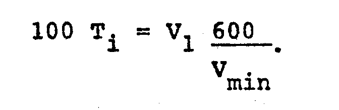
Der eigentliche Steuervorgang erfolgt nach dem Flußdiagramm der Fig. 3b. Nach Erkennung eines Tropfens durch den Tropfendetektor wird von dem Wert 100 Ti der Betrag von 100 subtrahiert. Wenn die Berechnung der Tropfenzahl T2 für den zweiten Kanal ergeben hat, daß in jeder öffnungsperiode des Ventils D2 5,35 Tropfen fallen sollen, dann wird von dem Wert 100 T. = 535 der Wert 100 subtrahiert. Außerdem wird geprüft, ob 100 T. kleiner ist als 100. Wenn 100 Ti größer oder gleich 100 ist, wird derselbe Vorgang anschließend wiederholt, sobald das Fallen des nächsten Tropfens erkannt worden. ist.The actual control process takes place according to the flow chart of FIG. 3b. After detection of a drop by the drop detector, the amount of 100 is subtracted from the value 100 T i . If the calculation of the number of drops T 2 for the second channel has shown that 5.35 drops should fall in each opening period of valve D2, then the
Wenn auf diese Weise der ursprüngliche Wert von 535 auf den Wert 35 reduziert worden ist, nachdem 5 Tropfen gefallen sind, ist 100 Ti kleiner als 100 geworden (nämlich 35). Dieser Restwert T. REST wird gespeichert, um für den nächsten Zyklus zur Verfügung zu stehen. Dann wird der Wert von i um 1 erhöht, d.h. es folgt die Verarbeitung für den nächsten Kanal. Bei dieser Verarbeitung wird der berechneten Tropfenzahl Ti der gespeicherte Restwert Ti REST hinzuaddiert, um den neuen Wert von Ti zu erhalten, mit dem dann die Verarbeitung in Abhängigkeit von dem Fallen der Tropfen wiederholt wird.In this way, if the original value of 535 has been reduced to 35 after 5 drops have fallen, 100 T i has become less than 100 (namely 35). This residual value T. REST is saved to be available for the next cycle. Then the value of i is increased by 1, ie processing for the next channel follows. In this processing, the calculated droplet number T i is added to the stored residual value T i REST in order to obtain the new value of T i , with which the processing is then repeated depending on the dropping of the droplets.
Auf die beschriebene Weise wird erreicht, daß bei nicht-ganzzahligen Tropfenzahlen (hier: 5,35 Tropfen) der Restbetrag (hier 0,35) nicht verlorengeht. Vielmehr werden die Restbeträge für denselben Kanal kumulativ aufaddiert. Bei dem gewählten Beispiel bedeutet dies, daß 100 Ti bei dem zweiten Zyklus den Wert 570 (535 + 35) hat und bei dem dritten Zyklus den Wert 605 (535 + 35 + 35). Bei dem dritten Zyklus werden daher nicht 5 Tropfen erzeugt, wie bei den beiden vorhergehenden Zyklen, sondern 6 Tropfen. Der verbleibende Restwert 5 wird gespeichert. Die Tropfenzahl, die in jedem Kanal abgegeben wird, ist daher von Zyklus zu Zyklus nicht immer genau gleich, sondern die Tropfenzahlen können um einen Tropfen voneinander abweichen.In the manner described, it is achieved that with non-integer drop numbers (here: 5.35 drops) the remaining amount (here 0.35) is not lost. Rather, the remaining amounts for the same channel are added up cumulatively. In the example chosen, this means that 100 T i has the value 570 (535 + 35) in the second cycle and 605 (535 + 35 + 35) in the third cycle. The third cycle therefore does not produce 5 drops as in the two previous cycles, but 6 drops. The remaining value 5 is saved. The number of drops dispensed in each channel is therefore not always exactly the same from cycle to cycle, but the number of drops may differ by one drop.
Durch die Berücksichtigung des Restbetrages wird eine sehr genaue Einhaltung der eingestellten Infusionsraten erzielt.By taking the remaining amount into account, the infusion rates set are adhered to very precisely.
Nach dem Flußdiagramm der Fig. 3c wird die Einhaltung der berechneten Grenzwerte für die Tropfenüberwachung geprüft. Ein Zeitglied (Timer) überwacht die Zeit zwischen einer bestimmten Anzahl von Tropfen (z.B. 25 Tropfen), wenn für das Fallen dieser Tropfen mehr oder weniger Zeit gebraucht wird als die berechneten Grenzwerte angeben, wird ein STOP-Befehl erzeugt. Liegt die Zeit für das Fallen von 25 Tropfen jedoch innerhalb des vorgegebenen Zeitfensters, dann wird der Betrieb der Vorrichtung und die Überwachung fortgesetzt.3c, the compliance with the calculated limit values for the drop monitoring is checked. A timer monitors the time between a certain number of drops (e.g. 25 drops), if more or less time is required to drop these drops than the calculated limit values, a STOP command is generated. However, if the time for the drop of 25 drops is within the specified time window, the operation of the device and the monitoring are continued.
Die Summenförderrate W = VI + V2 + V3 + V4 wird an einer Anzeigevorrichtung 26 des Steuergerätes 11 angezeigt. Auf diese Weise kann außer den einzelnen Infusionsraten auch die Gesamt-Infusionsrate abgelesen werden. Die Gesamt-Infusionsrate W wird über Leitung 14 (Fig. 1) der Pumpensteuerung 27 für die Pumpe 13 zugeführt. Die Pumpensteuerung 27 erhält außerdem das Signal des Durchflußmessers 15, das der tatsächlichen Föderrate entspricht. Durch Signalvergleich zwischen Sollwert W und Istwert kann festgestellt werden, ob alle Kanäle ordnungsgemäß arbeiten oder ob einer der Infusionsbehälter Al bis A4 leer geworden ist oder ob eine andere Störung stattgefunden hat. Ergibt sich eine größere Abweichung zwischen Sollwert und Istwert, dann gibt die Pumpensteuerung 27 ein entsprechendes Alarmsignal an das Steuergerät 11.The total delivery rate W = VI + V2 + V3 + V4 is displayed on a
In Fig. 4 ist ein Ausführungsbeispiel dargestellt, bei dem das Steuergerät 11' nicht ein Rechner, sondern eine elektrische Schaltung ist. Die Vorwahlschalter S1 bis S4, an denen die Förderraten V1 bis V4 eingestellt sind, sind an einen Minimalwertdetektor 30 angeschlossen, der den Minimalwert Vmin ermittelt und einer Rechenschaltung 31 zuführt. Diese Rechenschaltung empfängt außerdem die Werte der eingestellten Infusionsraten V1 bis V4 und bildet aus diesen Werten die Tropfenzahlen nach der Formel
In Fig. 4 ist nur die Weiterverarbeitung der Tropfenzahl T1 dargestellt. Die Tropfenzahlen T2 bis T4 werden in entsprechenden Schaltungen weiterverarbeitet, die aus Gründen der Übersichtlichkeit nicht dargestellt sind. Die Tropfenzahlen Ti werden bei dem Ausführungsbeispiel der Fig. 4 bis auf 2 Stellen hinter dem Komma angegeben. Die Tropfenzahl T1 wird einem Addierer 32 zugeführt. Der Ausgang des Addierers 32 ist mit einer Schaltung 33 verbunden, die von dem zugeführten Wert den Betrag von 1 subtrahiert, wenn von dem Tropfendetektor 22 ein Tropfen festgestellt wird. Der Ausgang der Schaltung 33 ist mit einem Komparator 34 verbunden, dem als Referenzsignal der Wert "1" zugeführt wird. Der Komparator 34 erzeugt ein Ausgangssignal, wenn der an seinem Eingang anstehende Wert mindestens "1,00" ist. Das Ausgangssignal des Komparators 34 öffnet eine Torschaltung 35, die das Ausgangssignal der Schaltung 33 auf den Eingang dieser Schaltung 33 zurückkoppelt. Beim nächstfolgenden Tropfen wird daher das Eingangssignal der Schaltung 33 um den Wert "1,00" verringert.In Fig. 4 only the further processing of the number of drops T 1 is shown. The drop numbers T 2 to T 4 are further processed in corresponding circuits, which are not shown for reasons of clarity. In the embodiment of FIG. 4, the drop numbers T i are given to two decimal places. The drop number T 1 is fed to an
Das Ausgangssignal des Komparators 34 wird über einen Inverter 35 dem Steueranschluß einer weiteren Torschaltung 36 zugeführt, welche das Rest-Signal T1 REST zu dem zweiten Eingang des Addierers 32 durchläßt, wenn der Wert am Eingang des Komparators 34 kleiner als "1,00" geworden ist. Das Ventil D1 wird durch den Komparator 34 solange geöffnet gehalten, solange der Komparator 34 feststellt, daß die an seinem Eingang anstehende Tropfenzahl größer ist als "1,00". Die Torschaltung 36 enthält ein Register, das denjenigen Restwert, der am Ende eines Zyklus vorhanden war, speichert und ihn beim Beginn des nächsten Zyklus dem Addierer 32 zuführt. Wenn der beschriebene Kanal 1 einen Zyklus beendet hat, wird der Kanal 2 in der gleichen Weise aktiviert, um die gleichen Rechenvorgänge auszuführen.The output signal of the
Claims (5)
dadurch gekennzeichnet, daß die Ablaufleitungen (B1 bis B4) jeweils eine belüftete Tropfkammer (C1 bis C4) mit einem Tropfendetektor (22) enthalten, daß das Steuergerät (11, 11') die Signale der Tropfendetektoren (22) empfängt und jeweils nach einer der Infusionsrate entsprechenden Trcpfenzahl die Umschaltung auf ein anderes Ventil vornimmt, daß das Steuergerät (11,11') einen Minimalwertdetektor enthält, der aus den eingegebenen Infusionsraten (V1 bis V4) die kleinste Infusionsrate (Vmin) ermittelt und dieser kleinsten Infusionsrate eine vorgegebene Mindesttropfenzahl zuordnet und daß das Steuergerät eine Recheneinrichtung (31) enthält, die den übrigen Infusionsraten die betreffenden Tropfenzahlen proportional zu der Mindesttropfenzahl (T . ) zuordnet.1.Device for the dosed simultaneous infusion of solutions-from several infusion containers (A1 to A4) with drain lines (B1 to B4) which lead from the containers to a collecting line (12) and each contain a controlled valve (D1 to D4), one Pump (13) provided in the collecting line (12) with a selectable delivery volume and with a control unit (11, 11 ') which cyclically opens the valves (D1 to D4) according to the set infusion rates (V1 to V4) of the individual solutions one after the other,
characterized in that the drain lines (B1 to B4) each contain a ventilated drip chamber (C1 to C4) with a drop detector (22), that the control device (11, 11 ') receives the signals from the drop detectors (22) and in each case according to one of the The number of drops corresponding to the infusion rate is switched to another valve so that the control unit (11, 11 ') contains a minimum value detector which determines the smallest infusion rate (V min ) from the entered infusion rates (V1 to V4) and assigns a predetermined minimum number of drops to this lowest infusion rate and that the control unit contains a computing device (31) which assigns the relevant number of drops to the remaining infusion rates in proportion to the minimum number of drops (T.).
Priority Applications (3)
| Application Number | Priority Date | Filing Date | Title |
|---|---|---|---|
| DE3329977A DE3329977C2 (en) | 1983-08-19 | 1983-08-19 | Device for the dosed simultaneous infusion of solutions |
| EP85100793A EP0189491A1 (en) | 1983-08-19 | 1985-01-26 | Device for dosed simultaneous infusing solutions |
| JP60024264A JPS61185276A (en) | 1983-08-19 | 1985-02-08 | Apparatus for dripping simultaneously prepared solution |
Applications Claiming Priority (3)
| Application Number | Priority Date | Filing Date | Title |
|---|---|---|---|
| DE3329977A DE3329977C2 (en) | 1983-08-19 | 1983-08-19 | Device for the dosed simultaneous infusion of solutions |
| EP85100793A EP0189491A1 (en) | 1983-08-19 | 1985-01-26 | Device for dosed simultaneous infusing solutions |
| JP60024264A JPS61185276A (en) | 1983-08-19 | 1985-02-08 | Apparatus for dripping simultaneously prepared solution |
Publications (1)
| Publication Number | Publication Date |
|---|---|
| EP0189491A1 true EP0189491A1 (en) | 1986-08-06 |
Family
ID=27191223
Family Applications (1)
| Application Number | Title | Priority Date | Filing Date |
|---|---|---|---|
| EP85100793A Withdrawn EP0189491A1 (en) | 1983-08-19 | 1985-01-26 | Device for dosed simultaneous infusing solutions |
Country Status (3)
| Country | Link |
|---|---|
| EP (1) | EP0189491A1 (en) |
| JP (1) | JPS61185276A (en) |
| DE (1) | DE3329977C2 (en) |
Cited By (25)
| Publication number | Priority date | Publication date | Assignee | Title |
|---|---|---|---|---|
| US4789014A (en) * | 1986-12-05 | 1988-12-06 | Baxter International Inc. | Automated system for adding multiple fluids to a single container |
| EP0343501A2 (en) * | 1988-05-21 | 1989-11-29 | Fresenius AG | Multiple infusion system |
| EP0361662A1 (en) * | 1988-08-15 | 1990-04-04 | Fresenius AG | Dual source parenteral infusion system with secondary infusion module |
| US5056568A (en) * | 1986-12-05 | 1991-10-15 | Clintec Nutrition Company | Automated system for adding multiple fluids to a single container |
| US5076332A (en) * | 1986-12-08 | 1991-12-31 | Clintec Nitrition Co. | Arch geometry to eliminate tubing influence on load cell accuracy |
| EP0658354A1 (en) * | 1993-11-23 | 1995-06-21 | Fresenius AG | Metering device for volumetric dispensing of a liquid additive |
| WO1996017637A1 (en) * | 1994-12-07 | 1996-06-13 | Midex Marketing Limited | Intravenous infusion flow rate monitoring device |
| WO1998022738A1 (en) * | 1996-11-19 | 1998-05-28 | Volker Lang | Microvalve |
| US7925330B2 (en) | 2004-11-24 | 2011-04-12 | Medrad, Inc. | Devices, systems and methods for determining parameters of one or more phases of an injection procedure |
| US8197437B2 (en) | 2004-11-16 | 2012-06-12 | Medrad, Inc. | Systems and methods of modeling pharmaceutical propagation in a patient |
| DE102013209903A1 (en) * | 2013-05-28 | 2014-12-04 | Hemedis Gmbh | Modular device for providing a multi-component mixed solution |
| US9008759B2 (en) | 2007-07-17 | 2015-04-14 | Bayer Medical Care Inc. | Devices and systems for determination of parameters for a procedure, for estimation of cardiopulmonary function and for fluid delivery |
| US9302044B2 (en) | 2006-12-29 | 2016-04-05 | Bayer Healthcare Llc | Patient-based parameter generation systems for medical injection procedures |
| US9421330B2 (en) | 2008-11-03 | 2016-08-23 | Bayer Healthcare Llc | Mitigation of contrast-induced nephropathy |
| US9700672B2 (en) | 2011-09-21 | 2017-07-11 | Bayer Healthcare Llc | Continuous multi-fluid pump device, drive and actuating system and method |
| US9949704B2 (en) | 2012-05-14 | 2018-04-24 | Bayer Healthcare Llc | Systems and methods for determination of pharmaceutical fluid injection protocols based on x-ray tube voltage |
| US9959389B2 (en) | 2010-06-24 | 2018-05-01 | Bayer Healthcare Llc | Modeling of pharmaceutical propagation and parameter generation for injection protocols |
| US10507319B2 (en) | 2015-01-09 | 2019-12-17 | Bayer Healthcare Llc | Multiple fluid delivery system with multi-use disposable set and features thereof |
| US10898638B2 (en) | 2016-03-03 | 2021-01-26 | Bayer Healthcare Llc | System and method for improved fluid delivery in multi-fluid injector systems |
| US11141535B2 (en) | 2017-08-31 | 2021-10-12 | Bayer Healthcare Llc | Fluid path impedance assessment for improving fluid delivery performance |
| US11278853B2 (en) | 2013-03-13 | 2022-03-22 | Bayer Healthcare Llc | Method for controlling fluid accuracy and backflow compensation |
| US11478581B2 (en) | 2017-08-31 | 2022-10-25 | Bayer Healthcare Llc | Fluid injector system volume compensation system and method |
| US11598664B2 (en) | 2017-08-31 | 2023-03-07 | Bayer Healthcare Llc | Injector pressure calibration system and method |
| US11779702B2 (en) | 2017-08-31 | 2023-10-10 | Bayer Healthcare Llc | Method for dynamic pressure control in a fluid injector system |
| US11786652B2 (en) | 2017-08-31 | 2023-10-17 | Bayer Healthcare Llc | System and method for drive member position and fluid injector system mechanical calibration |
Families Citing this family (10)
| Publication number | Priority date | Publication date | Assignee | Title |
|---|---|---|---|---|
| FR2593951B1 (en) * | 1986-02-03 | 1989-01-06 | Bertin & Cie | METHOD AND SYSTEM FOR REMOTE CONTROL OF AT LEAST ONE INFUSION STATION |
| US4834744A (en) * | 1987-11-04 | 1989-05-30 | Critikon, Inc. | Spike for parenteral solution container |
| JPH0277267A (en) * | 1988-09-14 | 1990-03-16 | Nikkiso Co Ltd | Liquid transfusing pump |
| DE3939247C1 (en) * | 1989-11-28 | 1991-05-23 | Fresenius Ag, 6380 Bad Homburg, De | |
| DE9017231U1 (en) * | 1990-12-21 | 1992-04-16 | Critikon Gmbh, 2000 Norderstedt, De | |
| DE4205718C2 (en) * | 1991-02-25 | 1996-01-18 | Sydow Friedrich Wilhelm Dr | Device for the simultaneous infusion of several infusion liquids into one patient |
| DE4137837C1 (en) * | 1991-11-18 | 1992-10-29 | Fresenius Ag, 6380 Bad Homburg, De | |
| DE4320365C2 (en) * | 1993-06-19 | 2000-07-13 | Uvo Hoelscher | Multi-channel dosing system |
| JP2009285128A (en) * | 2008-05-29 | 2009-12-10 | Nikkiso Co Ltd | Blood purifier and method of forming liquid reservoir in drip chamber for priming liquid |
| CN105853100A (en) * | 2016-05-06 | 2016-08-17 | 中国人民解放军第三军医大学第三附属医院 | Multi-adaptive patient self-care nursing equipment |
Citations (4)
| Publication number | Priority date | Publication date | Assignee | Title |
|---|---|---|---|---|
| FR2258870A1 (en) * | 1974-01-25 | 1975-08-22 | Bioengineering Research | Medical dosage electronic control unit providing constant output - has digital counters dosage keyboard and injection tube monitor |
| DE2730736A1 (en) * | 1976-07-09 | 1978-01-12 | Burron Medical Prod Inc | INFUSION DEVICE |
| DE2855713A1 (en) * | 1978-12-22 | 1980-06-26 | Doehn Manfred Priv Doz Dr Med | DEVICE FOR INFUSING SOLUTIONS FROM MULTIPLE INFUSION BOTTLES |
| WO1982003554A1 (en) * | 1981-04-15 | 1982-10-28 | Dean L Kamen | Fluid flow control system |
-
1983
- 1983-08-19 DE DE3329977A patent/DE3329977C2/en not_active Expired
-
1985
- 1985-01-26 EP EP85100793A patent/EP0189491A1/en not_active Withdrawn
- 1985-02-08 JP JP60024264A patent/JPS61185276A/en active Pending
Patent Citations (4)
| Publication number | Priority date | Publication date | Assignee | Title |
|---|---|---|---|---|
| FR2258870A1 (en) * | 1974-01-25 | 1975-08-22 | Bioengineering Research | Medical dosage electronic control unit providing constant output - has digital counters dosage keyboard and injection tube monitor |
| DE2730736A1 (en) * | 1976-07-09 | 1978-01-12 | Burron Medical Prod Inc | INFUSION DEVICE |
| DE2855713A1 (en) * | 1978-12-22 | 1980-06-26 | Doehn Manfred Priv Doz Dr Med | DEVICE FOR INFUSING SOLUTIONS FROM MULTIPLE INFUSION BOTTLES |
| WO1982003554A1 (en) * | 1981-04-15 | 1982-10-28 | Dean L Kamen | Fluid flow control system |
Cited By (40)
| Publication number | Priority date | Publication date | Assignee | Title |
|---|---|---|---|---|
| US4789014A (en) * | 1986-12-05 | 1988-12-06 | Baxter International Inc. | Automated system for adding multiple fluids to a single container |
| US4967811A (en) * | 1986-12-05 | 1990-11-06 | Clintec Nutrition Company | Automated system for adding multiple fluids to a single container |
| US5056568A (en) * | 1986-12-05 | 1991-10-15 | Clintec Nutrition Company | Automated system for adding multiple fluids to a single container |
| US5076332A (en) * | 1986-12-08 | 1991-12-31 | Clintec Nitrition Co. | Arch geometry to eliminate tubing influence on load cell accuracy |
| EP0343501A2 (en) * | 1988-05-21 | 1989-11-29 | Fresenius AG | Multiple infusion system |
| EP0343501A3 (en) * | 1988-05-21 | 1990-06-13 | Fresenius Ag | Multiple infusion system |
| EP0361662A1 (en) * | 1988-08-15 | 1990-04-04 | Fresenius AG | Dual source parenteral infusion system with secondary infusion module |
| EP0658354A1 (en) * | 1993-11-23 | 1995-06-21 | Fresenius AG | Metering device for volumetric dispensing of a liquid additive |
| US5512046A (en) * | 1993-11-23 | 1996-04-30 | Fresenius Ag | Dosing device for the volumetric dosing of a liquid additive |
| WO1996017637A1 (en) * | 1994-12-07 | 1996-06-13 | Midex Marketing Limited | Intravenous infusion flow rate monitoring device |
| WO1998022738A1 (en) * | 1996-11-19 | 1998-05-28 | Volker Lang | Microvalve |
| US9616166B2 (en) | 2004-11-16 | 2017-04-11 | Bayer Healthcare Llc | Systems and methods of determining injection protocols for diagnostic imaging procedures |
| US8295914B2 (en) | 2004-11-16 | 2012-10-23 | Medrad, Inc. | Systems and methods of determining patient transfer functions and modeling patient response to a pharmaceutical injection |
| US8346342B2 (en) | 2004-11-16 | 2013-01-01 | Medrad, Inc. | Systems and methods of determining patient physiological parameters from an imaging procedure |
| US8197437B2 (en) | 2004-11-16 | 2012-06-12 | Medrad, Inc. | Systems and methods of modeling pharmaceutical propagation in a patient |
| US9950107B2 (en) | 2004-11-24 | 2018-04-24 | Bayer Healthcare Llc | Systems and methods for managing workflow for injection procedures |
| US9238099B2 (en) | 2004-11-24 | 2016-01-19 | Bayer Healthcare Llc | System and apparatus for modeling pressures generated during an injection procedure |
| US7925330B2 (en) | 2004-11-24 | 2011-04-12 | Medrad, Inc. | Devices, systems and methods for determining parameters of one or more phases of an injection procedure |
| US10166326B2 (en) | 2004-11-24 | 2019-01-01 | Bayer Healthcare Llc | Devices, systems and methods for determining parameters of one or more phases of an injection procedure |
| US10463782B2 (en) | 2006-12-29 | 2019-11-05 | Bayer Healthcare Llc | Patient-based parameter generation systems for medical injection procedures |
| US9302044B2 (en) | 2006-12-29 | 2016-04-05 | Bayer Healthcare Llc | Patient-based parameter generation systems for medical injection procedures |
| US9008759B2 (en) | 2007-07-17 | 2015-04-14 | Bayer Medical Care Inc. | Devices and systems for determination of parameters for a procedure, for estimation of cardiopulmonary function and for fluid delivery |
| US9421330B2 (en) | 2008-11-03 | 2016-08-23 | Bayer Healthcare Llc | Mitigation of contrast-induced nephropathy |
| US9959389B2 (en) | 2010-06-24 | 2018-05-01 | Bayer Healthcare Llc | Modeling of pharmaceutical propagation and parameter generation for injection protocols |
| US9700672B2 (en) | 2011-09-21 | 2017-07-11 | Bayer Healthcare Llc | Continuous multi-fluid pump device, drive and actuating system and method |
| US11191501B2 (en) | 2012-05-14 | 2021-12-07 | Bayer Healthcare Llc | Systems and methods for determination of pharmaceutical fluid injection protocols based on x-ray tube voltage |
| US9949704B2 (en) | 2012-05-14 | 2018-04-24 | Bayer Healthcare Llc | Systems and methods for determination of pharmaceutical fluid injection protocols based on x-ray tube voltage |
| US11278853B2 (en) | 2013-03-13 | 2022-03-22 | Bayer Healthcare Llc | Method for controlling fluid accuracy and backflow compensation |
| DE102013209903A1 (en) * | 2013-05-28 | 2014-12-04 | Hemedis Gmbh | Modular device for providing a multi-component mixed solution |
| DE102013209903B4 (en) * | 2013-05-28 | 2017-05-11 | Hemedis Gmbh | Modular device for providing a multi-component mixed solution |
| US10507319B2 (en) | 2015-01-09 | 2019-12-17 | Bayer Healthcare Llc | Multiple fluid delivery system with multi-use disposable set and features thereof |
| US11491318B2 (en) | 2015-01-09 | 2022-11-08 | Bayer Healthcare Llc | Multiple fluid delivery system with multi-use disposable set and features thereof |
| US10898638B2 (en) | 2016-03-03 | 2021-01-26 | Bayer Healthcare Llc | System and method for improved fluid delivery in multi-fluid injector systems |
| US11672902B2 (en) | 2016-03-03 | 2023-06-13 | Bayer Healthcare Llc | System and method for improved fluid delivery in multi-fluid injector systems |
| US11141535B2 (en) | 2017-08-31 | 2021-10-12 | Bayer Healthcare Llc | Fluid path impedance assessment for improving fluid delivery performance |
| US11478581B2 (en) | 2017-08-31 | 2022-10-25 | Bayer Healthcare Llc | Fluid injector system volume compensation system and method |
| US11598664B2 (en) | 2017-08-31 | 2023-03-07 | Bayer Healthcare Llc | Injector pressure calibration system and method |
| US11779702B2 (en) | 2017-08-31 | 2023-10-10 | Bayer Healthcare Llc | Method for dynamic pressure control in a fluid injector system |
| US11786652B2 (en) | 2017-08-31 | 2023-10-17 | Bayer Healthcare Llc | System and method for drive member position and fluid injector system mechanical calibration |
| US11826553B2 (en) | 2017-08-31 | 2023-11-28 | Bayer Healthcare Llc | Fluid path impedance assessment for improving fluid delivery performance |
Also Published As
| Publication number | Publication date |
|---|---|
| DE3329977C2 (en) | 1985-10-17 |
| DE3329977A1 (en) | 1985-03-07 |
| JPS61185276A (en) | 1986-08-18 |
Similar Documents
| Publication | Publication Date | Title |
|---|---|---|
| DE3329977C2 (en) | Device for the dosed simultaneous infusion of solutions | |
| EP0658354B1 (en) | Metering device for volumetric dispensing of a liquid additive | |
| DE4320365C2 (en) | Multi-channel dosing system | |
| DE60127482T2 (en) | Water purification system with measurement and control of delivery | |
| DE2428485C2 (en) | Arrangement for the delivery of seeds | |
| DE2640413C3 (en) | Catheter monitor | |
| DE2720210B2 (en) | Apparatus for calibrating a probe in a blood sample measuring device | |
| EP0013334A2 (en) | Device for infusing solutions from several infusion bottles | |
| DE2447395B2 (en) | Distribution device for liquids, in particular in agriculture | |
| DE2027087A1 (en) | Device for pentonaal dialysis | |
| WO1985002546A1 (en) | Infusion device | |
| DE2708422C2 (en) | Device for the impulse delivery of very small amounts of liquid, especially H2O2 | |
| EP3429544B1 (en) | Method for producing a medical preparation using a hose pump | |
| DE1498311A1 (en) | Drop feed device | |
| DE1947549A1 (en) | Milking system | |
| DE2944186C2 (en) | Device for introducing liquids into a human or animal body | |
| DE3824744A1 (en) | Agricultural field sprayer | |
| DE3138478C2 (en) | ||
| DE69532920T2 (en) | Device for the volumetric delivery of liquids | |
| DE69629867T2 (en) | Method of feeding and collecting solutions | |
| DE2504792A1 (en) | DEVICE FOR SUPPLYING FLOWING MEDIA | |
| DE3514668C2 (en) | ||
| DE3202314C2 (en) | Device for admixing liquid chemicals to liquids | |
| DE3922952C2 (en) | ||
| EP0478944A1 (en) | Device for proportioning and mixing two fluid components |
Legal Events
| Date | Code | Title | Description |
|---|---|---|---|
| PUAI | Public reference made under article 153(3) epc to a published international application that has entered the european phase |
Free format text: ORIGINAL CODE: 0009012 |
|
| 17P | Request for examination filed |
Effective date: 19851106 |
|
| AK | Designated contracting states |
Kind code of ref document: A1 Designated state(s): AT BE CH DE FR GB IT LI LU NL SE |
|
| 17Q | First examination report despatched |
Effective date: 19870918 |
|
| STAA | Information on the status of an ep patent application or granted ep patent |
Free format text: STATUS: THE APPLICATION IS DEEMED TO BE WITHDRAWN |
|
| 18D | Application deemed to be withdrawn |
Effective date: 19880129 |
|
| RIN1 | Information on inventor provided before grant (corrected) |
Inventor name: ANIS, PETER Inventor name: ROSSKOPF, GERHARD, DR. |