EP0192624A2 - Lightweight battery powered suction broom - Google Patents
Lightweight battery powered suction broom Download PDFInfo
- Publication number
- EP0192624A2 EP0192624A2 EP86850055A EP86850055A EP0192624A2 EP 0192624 A2 EP0192624 A2 EP 0192624A2 EP 86850055 A EP86850055 A EP 86850055A EP 86850055 A EP86850055 A EP 86850055A EP 0192624 A2 EP0192624 A2 EP 0192624A2
- Authority
- EP
- European Patent Office
- Prior art keywords
- assembly
- mounting
- vacuum cleaner
- canister
- nozzle
- Prior art date
- Legal status (The legal status is an assumption and is not a legal conclusion. Google has not performed a legal analysis and makes no representation as to the accuracy of the status listed.)
- Granted
Links
Images


Classifications
-
- A—HUMAN NECESSITIES
- A47—FURNITURE; DOMESTIC ARTICLES OR APPLIANCES; COFFEE MILLS; SPICE MILLS; SUCTION CLEANERS IN GENERAL
- A47L—DOMESTIC WASHING OR CLEANING; SUCTION CLEANERS IN GENERAL
- A47L5/00—Structural features of suction cleaners
- A47L5/12—Structural features of suction cleaners with power-driven air-pumps or air-compressors, e.g. driven by motor vehicle engine vacuum
- A47L5/22—Structural features of suction cleaners with power-driven air-pumps or air-compressors, e.g. driven by motor vehicle engine vacuum with rotary fans
- A47L5/24—Hand-supported suction cleaners
Definitions
- This invention relates to vacuum cleaners, and more in particular a vacuum cleaner apparatus especially adapted for hand held, portable operation.
- the invention is directed to the provision of a portable vacuum cleaner that is readily and economically fabricated, and easy and reliable to use, and that may be recharged in a simple manner.
- a portable vacuum cleaner is comprised of a frame encorporating a mounting assembly for pivotally mounting a nozzle assembly, and a power assembly including a vacuum pump.
- the mounting assembly and the power assembly are spaced apart on the frame, so that a filter bag assembly may be removably received therebetween.
- the nozzle assembly is comprised of lower and upper nozzle sections adapted to be assembled on opposite sides of a hollow mounting cylinder of the mounting assembly, in order to permit limited pivotal movement of the nozzle assembly.
- Forward and rear wheels are provided in the lower nozzle section.
- a recess extends transversely in the bottom of the lower nozzle section, terminating in a central aperture communicating with the hollow mounting cylinder, in order to direct air from the nozzle assembly to the vacuum pump.
- the filter bag assembly is comprised of a canister adapted to be removable fit on the frame between the mounting assembly and the power assembly.
- the canister is pivoted at the mounting assembly and held by a latch at the power assembly.
- a longitudinal groove in the bottom of the canister receives a bar-shaped element of the frame, both to inhibit lateral displacement of the canister and to join the power assembly to the nozzle assembly, thus enabling a pleasing appearance of the structure.
- the canister removably receives a filter bag.
- the power assembly incorporates a battery and recharging circuit, so that when the mounting projection of a mounting base is received in a recess of the power assembly, for storage of the vacuum cleaner, an electrical interconnection enables recharging of the operating battery.
- the assembly is comprised of a frame 100 having a power assembly 200 on one end and a mounting assembly 300 on its other end for pivotally holding a nozzle assembly 400 comprised of an upper nozzle section 500 and a lower nozzle section 600.
- a filter assembly 700 is adapted to be removably snapped to the frame, between the mounting assembly 300 and the power assembly 200, a filter bag 750 being mounted in the filter assembly 700 and being held in shape therein by a bag support 760.
- a handle 800 is affixed to the frame 100, for example in the power assembly 200 thereof.
- a charging mount 900 for example adapted to be mounted to a wall 980, has a mounting projection 901 adapted to be received in a recess 201 of the power assembly, thereby to enable the vacuum cleaner assembly to be hung on a wall and simultaneously charged.
- suitable electrical connections are provided in the mounting projection 901 and in power assembly 200 in order to enable charging of the batteries of the power assembly when it is not in use.
- the power assembly which includes a vacuum pump 200 is adapted to draw air through the nozzle assembly 400, thence through the mounting assembly 300 into the filter assembly 700.
- the air is drawn through the filter bag of the filter assembly, exiting into the vacuum pump 210 in the power assembly. Dirt drawn through the vacuum cleaner nozzle will hence collect on the outside of the filter bag and in the filter assembly canister.
- the filter assembly 700 may be readily disassembled from the frame. For example, as illustrated in the Fig. 5, upon depression (i.e. drawing toward the rear) of a latch button 202, the rear of the filter assembly 700 may be pivoted away from the frame, the forward end thereof being formed to pivot in the mounting assembly 300.
- the terms “rearwardly” or “rear” side refer to the direction toward the handle, whereas the “forward” direction refers to the direction towards the nozzle assembly.
- the frame of the vacuum cleaner in accordance with the invention is illustrated in more detail in Figs. 7-11.
- the frame is preferably moulded from a high impact plastic of conventional material, and may be formed in two longitudinal halves adapted to be held together by any conventional means, such as screws.
- the frame 100 may be comprised of a generally bar-shaped support 101.
- the mounting assembly 300 is comprised of a hollow base 301 affixed to one end of the bar-shaped support 101, the rearward side 302 of the base 301 being inclined to the longitudinal direction of the bar-shaped support 101.
- an angle A of about 30 degrees may be provided between the plane of the side 302 of the base and the perpendicular to the longitudinal direction of the bar-shaped support 101.
- the upper surface 102 of the bar-shaped support 101 is generally planar, the base 301 of the mounting assembly defining a rearwardly extending rim 303 about its periphery and terminating at the bar-shaped support 101 in the plane of the surface 102.
- the rim 303 of the mounting assembly serves to hold and provide a pivot surface for the filter assembly, the filter assembly being formed to laterally surround the bar-shaped support 101 to laterally support the filter assembly in an esthetic manner.
- the term "upper” refers to the direction away from the side of the vacuum cleaner adapted to be adjacent a mounting wall when the vacuum cleaner is held on the wall mounted charging mount 900.
- a hollow pivot cylinder 310 is affixed to the front side of the base 301 by a forwardly extending mounting stub 311.
- the axis of the pivot cylinder extends transversely of the vacuum cleaner, i.e., normal to a vertical longitudinal plane extending through the vacuum cleaner, the term "vertical” referring of course to a plane extending in the upward direction as above defined.
- the pivot cylinder has end walls 320,321, joined by an upper partial circumferential wall 322 and a lower partial circumferential wall 323.
- the forward circumferential gap 324 between the circumferential walls 322 and 323 defines a passageway for air, from the forward end of the mounting assembly through the rear end thereof.
- the rear ends of the walls 320 and 321 and partial circumferential walls 322 and 323 of the pivot cylinder are rearwardly extended through the stub 311, to laterally enclose the defined passageway laterally.
- An axially extending annular projection 340 is provided depending from the outside of each end wall 320,321, for serving as a labyrinth seal with the nozzle assembly, and to provide a pivoting surface, as will be discussed.
- suitable screw holes may be provided therein such as the screw hole 350 of the pivot cylinder, the screw holes 110 on the bar shaped element, and the screw holes 290 in the power assembly, each adapted to receive a self-tapping screw (not shown).
- the pivot cylinder 310 is adapted to pivotally mount the nozzle assembly to the vacuum cleaner, and sealingly direct air from the nozzle assembly to the filter assembly.
- the nozzle assembly is illustrated in detail in Figs. 12-25, Figs. 12-19 Illustrating the lower nozzle section and Figs. 20-25 illustrating the upper nozzle section.
- the lower nozzle section is comprised of a moulded plastic shell 610 having a lower surface 611 and an upwardly extending rim 612 depending therefrom.
- the upper nozzle section is comprised of a moulded plastic shell 510 having an upper surface 511 and a downwardly extending rim 512 depending therefrom, the rim 512 of the upper nozzle section being adapted to vertically abut the top of the rim 612 of the lower nozzle section.
- the upper and lower nozzle sections are adapted to be held together by any conventional means, such as screws.
- downwardly extending studs 520 of the upper nozzle section are adapted to abut the top of the bottom surface of the lower nozzle section adjacent recessed holes 620 of the lower nozzle section when the upper and lower nozzle sections are assembled together, so that suitable screws (not shown) extending through the recessed holes 620 may be threaded into the studs 520.
- the shells which form the upper and lower nozzle sections are generally rectangular, with the longer dimension thereof extending transversely of the vacuum cleaner, i.e., in the direction of the axis of the pivot cylinder 320 of the mounting assembly 300.
- the moulded shell 610 has a pair of generally rectangular apertures 630 extending therethrough adjacent its forward edge 632, the apertures being symmetrically located on opposite sides of the center of the bottom (i.e. the axial center of the pivot cylinder 310 of the mounting assembly 300, when the nozzle is assembled thereto).
- a pair of short walls 632 are provided extending upwardly adjacent the sides of each of the recesses 630, the upper surface of the walls 632 each having a transversely extending groove for receiving the shaft 635 of a forward wheel 636, the forward wheels having a diameter to extend through the apertures 630 to serve as floor engaging wheels.
- Axial displacement of the forward wheels is prevented by projections 637 extending upwardly from the bottom of the bottom surface 610, to axially abut the shaft 635 at each end.
- the shaft 635 is vertically retained in the grooves in the walls 632 by downwardly extending short walls 530 of the upper nozzle section (Figs. 20-25), the bottom end of the short walls 530 abutting the tops of the short walls 632 of the lower nozzle section.
- a generally rectangular rear extension 640 is provided on the lower nozzle section for receiving the rear roller wheels 641.
- the bottom surface of the rear extension 640 is generally alined with the bottom 610.
- the rear extension 640 has a pair of rectangular recesses 642 extending upwardly from its bottom surface, on opposite sides of the center of the lower nozzle section, the recesses (which preferably have closed tops) receiving the rear roller wheels 641.
- the shafts 643 of the roller wheels 641 extend into side recesses 644 of the recess 642, the recesses 644 being peened over or otherwise deformed so that the shafts 643 may be inserted thereinto and held during use of the vacuum cleaner.
- a pair of walls 650 are provided extending upwardly from the bottom 610 of the lower nozzle section, and symmetrically on opposite sides of the center thereof and adjacent the rear 651 thereof, the walls 650 extending above the top of the rim 612 and having semicircular recesses 652 in their upper surfaces, substantially equal in diameter to the diameter of the annular projections 340 of the pivot cylinder 310 of the mounting assembly 300 of Figs. 7-11.
- These walls 650 are spaced apart a distance so that when the nozzle is assembled on the pivot cylinder, the circumferences of the annular projections 340 engage the semicircular recesses 652.
- Corresponding downwardly extending walls 550 are provided on the upper nozzle section (Figs. 20-25), the walls 550 having semicircular recesses 551 in their lower edges for engaging the circumferences of the annular projections 340 of the pivot cylinder.
- the bottoms of the walls 550 are positioned to engage the top surfaces of the walls 650, so that the semicircular recesses of the walls 650 and 550 substantially completely surround the annular projection 340 of the pivot cylinder to hold the nozzle assembly and mounting assembly together and to permit limited pivoting movement of the nozzle assembly. Since the walls 650 of the lower nozzle portion extend above the lower nozzle section as seen in Fig. 16, the center of the upper nozzle section has a raised boss 560, from which the walls 550 extend downwardly.
- the rear of the boss 560 has a recess 551 cut out therefrom to enable the stub 311 of the pivot cylinder therethrough, and to permit the pivotal movement of the nozzle assembly.
- the upper nozzle section is first assembled onto the pivot cylinder, after which the bottom nozzle section is affixed to the upper nozzle section. Since the annular projections 340 extend to engage the semicircular recesses of the nozzle sections, the nozzle cannot be removed from the mounting assembly without first separating the upper and lower nozzle sections.
- the lower surface 601 of the bottom nozzle section has an upwardly extending recess 660, the recess 660 having a central portion 661 extending transversely of the vacuum cleaner and terminating at end portions 662 extending to the front corners 663 of the lower nozzle section.
- An aperture 668 extends through the bottom of the nozzle section, to enable communication between recess 660 and the passageway 324 through the pivot cylinder 310. Since the power assembly of the vacuum cleaner is drawing air from the nozzle through the filter, it is apparent that the recess 660 forms a channel creating a flow path from the front corners of the nozzle.
- This channel enhances the ability of the nozzle to pick up dirt at the corners of the nozzle, it being apparent of course that, since the recess 660 extends across the entire bottom nozzle section, dirt is picked up by the nozzle throughout its width, as the nozzle is moved across the surface to be cleaned.
- the lower nozzle portion is further provided with walls 670 spaced from the outside of the walls 650, the upper nozzle section being provided with corresponding downwardly extending walls 570 adapted to abut the walls 670.
- the walls 570 and 670 hence inhibit the flow of air axially to the pivot cylinder from the interior of the nozzle.
- the lower and upper nozzle sections are preferably provided with seals 670 and 570 respectably for engaging the pivot cylinder, to inhibit the escape of air through the rotating pivot joint.
- the lower and upper nozzle sections may be provided with suitably shaped surfaces for holding seals 665,565 to engage the end portions 320,321 of the pivot cylinder as well as transversely extending seal portions 666 positioned to abut the arcuate wall portions 323 and 322 respectively of the pivot cylinder.
- the power assembly 200 is comprised of a housing 204 affixed to the rear of the bar-shaped support 101, for enclosing the vacuum pump and electrical control circuits.
- the housing 204 has an upwardly extending central front wall 205 with a central hole 203 for receiving air from the filter assembly.
- the wall 205 extends generally perpendicular to the plane of the top surface 102.
- the outer portions of the front of the housing 204 are defined by a wall 206 inclined to the plane of the top surface 102 and away from the mounting assembly to enable receiving the seal of the filter assembly as will be discussed later.
- the inner edge of the wall 206 is joined to the vertical wall 205.
- a vacuum pump 210 is mounted immediately behind the wall 205, as illustrated in Fig. 44, for receiving air through the hole 203 and ejecting it through side ports 207 of the housing 204.
- a motor 208 drives the vacuum pump, and is mounted to the rear of the vacuum pump.
- An operating switch 209 is mounted in the housing 204, having an actuator 211.
- a plastic button 212 engages the actuator 211 and is slidably mounted in a suitable slot in the housing wall.
- Suitable support walls 213 are provided in the housing for holding a rechargeable battery 214, such as a NiCd battery.
- a charging lamp 215, such as a LED, is mounted on the top of the housing 204, to provide an indication of charging of the battery.
- a connector 216 is mounted in the bottom of the recess 201, for engaging a mating connector 905 in the charging mount (Fig. 41).
- a circuit board 217 is mounted within the housing 204 at the rear of the connector 216, to carry further electrical components of the circuit.
- the switch 211 is connected to enable the application of current from the battery 214 to the motor 208.
- the charging circuit is comprised of a rectifier 230 connected between one of the terminals of the connector 216 and one terminal of the battery 214, the other terminal of the connector 216 being connected directly to the other terminal of the battery.
- the voltage applied to the connector 216 is an AC voltage, and is stepped down by the wall socket transformer 925 connected to the charging mount, as illustrated in Fig. 6.
- the charging indicating lamp 215 in connected to the connector 216 by way of a dropping resistor 240 and diode 241, for limiting the indicator current and blocking reverse voltage on the indicator lamp.
- the filter assembly is illustrated in Figs. 26-35 and 44.
- the filter assembly is comprised of a hollow canister 701 having a forward end 702 and a rear end 703.
- the forward end 702 is shaped to fit into the rim 303 of the mounting assembly, as illustrated in Figs. 6 and 44, to abut the seal 380 surrounding the passageway 324 of the mounting assembly.
- the rear end 703 of the canister is inclined to the plane of the surface 102, so that it may sealingly engage the inclined forward end 206 of the power assembly.
- the canister further has a longtitudinally extending recess 704 in its bottom, to receive the frame 100.
- the canister of the filter assembly is installed on the vacuum cleaner by inserting the forward end into the rim 303 of the mounting assembly, and then pivoting the rear of the canister downwardly until its inclined rear surface abuts the inclined forward surface 206 of the power assembly. In this position, the longtitudinal recess 704 of the canister receives the frame 100, to inhibit any side wise movement of the canister with respect to the mounting assembly and power assembly. Further, as apparent in Figs. 2-4, when the canister is thus installed, the bottom of the frame is flush with the bottom of the canister, to form a smooth esthetic appearance. The pivoting of the canister, during the assembly is illustrated in Fig. 5.
- the catch 202 on the rear end of the top of the power assembly slidingly engages a lip 705 extending rearwardly from the top of the rear surface 703 of the canister.
- the catch 202 is urged forwardly by a spring 203 provided in a suitable recess in the power assembly housing 204, as illustrated in Figs. 8 and 44. Consequently, manually urging the catch 202 enables release of the canister, so that it may be pivoted away from and removed from the vacuum cleaner. Since the forward end of the canister pivots in the mounting assembly, the inclined rear edge of the canister meets the inclined forward surface 206 of the power assembly at the position where the catch 202 engages the projection 705 of the canister, to lock the canister in place.
- the forward end 702 of the canister communicates with the interior of the canister by way of a longitudinally extending port 706 which extends a short distance into the canister.
- a flap valve 707 is mounted on the rear end of the port 706.
- the flap valve may be comprised, for example, of a flexible plastic or rubber sheet affixed, for example, to the bottom of the rear of the port 706.
- the flap valve 707 permits flow of air rearwardly through the port 706 and into the canister, but inhibits the flow of air in the reverse direction.
- the filter bag assembly 750 is comprised of a bag holding ring 751 and a filter bag 752.
- the holding ring 751 is shaped to fit within the front end 703 of the canister, and be supported against the front edges of 711 of longitudinally extending ribs 712, their front edges 711 being set back from the front edge 703.
- the holding ring 751 has a rearwardly extending flange 753 over which the front end of the filter bag 752 extends and is held by any conventional means.
- the bag 752 thus extends into the canister 701.
- the ring 751 is sufficiently rigid to hold the bag 752, and has a flexible sealing lip 754 extending around its forward surface, to form a seal against the inclined surface 206 of the power assembly.
- the holding ring 751 which may be of plastic or rubber material, further has a recess 755 adjacent its forward end for receiving and holding the forward rim 761 of the bag support 760, as illustrated in Fig. 44.
- the bag support 760 defines a forwardly extending cage 765, extending into the bag 752, to hold the shape of the bag, as illustrated for example in Fig. 44.
- the filter bag assembly 750 may be removed from the canister for cleaning, as illustrated in Fig. 26.
- the canister is first removed from the vacuum cleaner by releasing it by means of the catch 202, and pivoting it out and away from the vacuum cleaner.
- the filter bag assembly 750 is then withdrawn from the front of the canister along with the bag support 760 held therein, and the dirt then shaken from the outside of the bag and from the interior of the canister into a suitable waste receptacle.
- the bag assembly may then be reassembled in the canister, and the canister reassembled on the vacuum cleaner as discussed above.
- the charging mount for supporting the vacuum cleaner when not in use, while simultaneously recharging the batteries therein, is illustrated in Figs. 36-43.
- the charging mount which may be formed of a moulded plastic material, has a base 910 adapted to be mounted to a wall, for example by means of screw holes 911.
- the mounting projection 901 extends upwardly at an angle from the base, and is shaped to be received in the similarly inclined mounting recess 201 of the power assembly.
- the connector 905 is held within the mounting projection 901, as Illustrated in Fig. 41, for example in a suitably shaped recess in an interior wall 914 of the mounting projection.
- the connector 905 is connected in conventional manner to the wall transformer 925 (Fig. 6) by way of cord 927.
- FIG. 45 An internal circuit that may be employed in the vacuum cleaner of the invention is illustrated in Fig. 45, wherein it is seen that the motor 208 is connected to the rechargeable battery 214 by way of the operating switch 211.
- the recharging terminals 216 to which the output of the recharging transformer 925 is applied, are connected to opposite terminals of the battery 214 by way of charging rectifier 230, so that the battery may be continually charged when the vacuum cleaner is mounted on the charging mount.
- the charging of the battery is indicated by the LED-indicator 215, connected to the terminals 216 by way of the rectifier 241 and dropping resistor 240.
Abstract
Description
- This invention relates to vacuum cleaners, and more in particular a vacuum cleaner apparatus especially adapted for hand held, portable operation.
- The invention is directed to the provision of a portable vacuum cleaner that is readily and economically fabricated, and easy and reliable to use, and that may be recharged in a simple manner.
- Briefly stated, in accordance with the invention, a portable vacuum cleaner is comprised of a frame encorporating a mounting assembly for pivotally mounting a nozzle assembly, and a power assembly including a vacuum pump. The mounting assembly and the power assembly are spaced apart on the frame, so that a filter bag assembly may be removably received therebetween.
- The nozzle assembly is comprised of lower and upper nozzle sections adapted to be assembled on opposite sides of a hollow mounting cylinder of the mounting assembly, in order to permit limited pivotal movement of the nozzle assembly. Forward and rear wheels are provided in the lower nozzle section. A recess extends transversely in the bottom of the lower nozzle section, terminating in a central aperture communicating with the hollow mounting cylinder, in order to direct air from the nozzle assembly to the vacuum pump.
- The filter bag assembly is comprised of a canister adapted to be removable fit on the frame between the mounting assembly and the power assembly. The canister is pivoted at the mounting assembly and held by a latch at the power assembly. A longitudinal groove in the bottom of the canister receives a bar-shaped element of the frame, both to inhibit lateral displacement of the canister and to join the power assembly to the nozzle assembly, thus enabling a pleasing appearance of the structure. The canister removably receives a filter bag.
- The power assembly incorporates a battery and recharging circuit, so that when the mounting projection of a mounting base is received in a recess of the power assembly, for storage of the vacuum cleaner, an electrical interconnection enables recharging of the operating battery.
- In order that the invention may be more clearly understood, it will now be disclosed in greater detail with reference to the accompanying drawings, wherein:
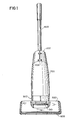
- Fig. 1 is a front view of the vacuum cleaner of the invention;
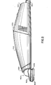
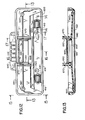
- Fig. 2 is an enlarged side view of a portion of the vacuum cleaner of Fig. 1;
- Fig. 3 is a side view of the vacuum cleaner of Fig. 1;
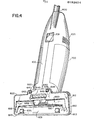
- Fig. 4 is an enlarged bottom view of a portion of the vacuum cleaner of Fig. 1;
- Fig. 5 is a top perspective view of the vacuum cleaner of Fig. 1, with the filter assembly canister partially removed;
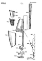
- Fig. 6 is an exploded view of the vacuum cleaner of Fig. 1;
- Fig. 7 is a side view of the frame of the vacuum cleaner of Fig. 1;
- Fig. 8 is a longitudinal cross sectional view of the housing of the frame;
- Fig. 9 is an enlarged longitudinal view of a portion of the forward end or mounting assembly of the frame housing;
- Fig. 10 is a top view of the portion of the frame housing illustrated in Fig. 9;
- Fig. 11 is a transverse cross sectional view taken along the lines 11-11 of Fig. 10;
- Fig. 12 is a top view of the lower nozzle section of the vacuum cleaner;
- Fig. 13 is a cross sectional view of the lower nozzle section taken along the lines 13-13 of Fig. 12;
- Fig. 14 is an enlarged cross sectional view of a forward wheel assembly taken along the lines 14-14 of Fig. 12;
- Fig. 15 is a side view of the lower nozzle section in the direction indicated by the lines 15-15 of Fig. 12;
- Fig. 16 is a transverse cross sectional view of the lower nozzle section taken along the lines 16-16 of Fig. 12;
- Fig. 17 is a transverse cross sectional view of the lower nozzle section taken along the lines 17-17 of Fig. 12,
- Fig. 18 is a bottom view of the lower nozzle section;
- Fig. 19 is a rear view of the lower nozzle section;
- Fig. 20 is a front view of the upper nozzle section of the vacuum cleaner;
- Fig. 21 is a top view of the upper nozzle section;
- Fig. 22 is a longitudinal cross sectional view of the upper nozzle section taken along the lines 22-22 of Fig. 21;
- Fig. 23 is a bottom view of the upper nozzle section;
- Fig. 24 is an end view of the upper nozzle section;
- Fig. 25 is a transverse cross sectional view of the upper nozzle section taken along the lines 25-25 of Fig. 21;
- Fig. 26 is a perspective view of the filter assembly of the vacuum cleaner;
- Fig. 27 is a longitudinal cross sectional view of the canister of the filter assembly;
- Fig. 28 is an exploded partially cross sectional view of the filter assembly;
- Fig. 29 is a side view of the canister;
- Fig. 30 is a bottom view of the canister;
- Fig. 31 is a rear view of the bag support;
- Fig. 32 is a rear view of the bag holder ring;
- Fig. 33 is a top view of the canister;
- Fig. 34 is a rear end view of the canister, as seen along the lines 34-34 of Fig. 33;
- Fig. 35 is a front end view of the canister, as seen along the lines 35-35 of Fig. 33;
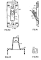
- Fig. 36 is a front view of the charging mount of the vacuum cleaner;
- Fig. 37 is a side view of the charging mount;
- Fig. 38 is a bottom view of the charging mount;
- Fig. 39 is a top view of the charging mount housing;
- Fig. 40 is a rear view of the charging mount housing;
- Fig. 41 is a vertical cross sectional view of the charging mount housing taken along the lines 41-41 of Fig. 40 and including the connector thereof;
- Fig. 42 is an enlarged cross sectional view of the charging mount housing taken along the lines 42-42 of Fig. 37;
- Fig. 43 is an upper end view of the mounting projection of the charging mount, taken in the direction of the lines 43-43 of Fig. 37;
- Fig. 44 a longitudinal cross sectional view of the assembled vacuum cleaner; and
- Fig. 45 is a circuit diagram of the vacuum cleaner.
- Referring now to the drawings, and more in particular to Figs. 1-6, therein is Illustrated a vacuum cleaner system in accordance with the invention. The assembly is comprised of a
frame 100 having apower assembly 200 on one end and a mountingassembly 300 on its other end for pivotally holding anozzle assembly 400 comprised of anupper nozzle section 500 and alower nozzle section 600. Afilter assembly 700 is adapted to be removably snapped to the frame, between the mountingassembly 300 and thepower assembly 200, afilter bag 750 being mounted in thefilter assembly 700 and being held in shape therein by abag support 760. Ahandle 800 is affixed to theframe 100, for example in thepower assembly 200 thereof. A charging mount 900, for example adapted to be mounted to awall 980, has a mountingprojection 901 adapted to be received in arecess 201 of the power assembly, thereby to enable the vacuum cleaner assembly to be hung on a wall and simultaneously charged. As will be discussed, suitable electrical connections are provided in the mountingprojection 901 and inpower assembly 200 in order to enable charging of the batteries of the power assembly when it is not in use. - As is readily apparent in the exploded diagram of Fig. 6 and the cross sectional view of Fig. 44, the power assembly, which includes a
vacuum pump 200 is adapted to draw air through thenozzle assembly 400, thence through the mountingassembly 300 into thefilter assembly 700. The air is drawn through the filter bag of the filter assembly, exiting into thevacuum pump 210 in the power assembly. Dirt drawn through the vacuum cleaner nozzle will hence collect on the outside of the filter bag and in the filter assembly canister. In order to discard such dirt, thefilter assembly 700 may be readily disassembled from the frame. For example, as illustrated in the Fig. 5, upon depression (i.e. drawing toward the rear) of alatch button 202, the rear of thefilter assembly 700 may be pivoted away from the frame, the forward end thereof being formed to pivot in the mountingassembly 300. - As employed hereafter in this disclosure, the terms "rearwardly" or "rear" side, refer to the direction toward the handle, whereas the "forward" direction refers to the direction towards the nozzle assembly.
- The frame of the vacuum cleaner in accordance with the invention is illustrated in more detail in Figs. 7-11. The frame is preferably moulded from a high impact plastic of conventional material, and may be formed in two longitudinal halves adapted to be held together by any conventional means, such as screws.
- The
frame 100 may be comprised of a generally bar-shapedsupport 101. The mountingassembly 300 is comprised of ahollow base 301 affixed to one end of the bar-shapedsupport 101, therearward side 302 of the base 301 being inclined to the longitudinal direction of the bar-shapedsupport 101. For example, an angle A of about 30 degrees may be provided between the plane of theside 302 of the base and the perpendicular to the longitudinal direction of the bar-shapedsupport 101. - The
upper surface 102 of the bar-shapedsupport 101 is generally planar, thebase 301 of the mounting assembly defining arearwardly extending rim 303 about its periphery and terminating at the bar-shapedsupport 101 in the plane of thesurface 102. As will be apparent in the following discussion of the filter assembly, therim 303 of the mounting assembly serves to hold and provide a pivot surface for the filter assembly, the filter assembly being formed to laterally surround the bar-shapedsupport 101 to laterally support the filter assembly in an esthetic manner. As employed herein the term "upper" refers to the direction away from the side of the vacuum cleaner adapted to be adjacent a mounting wall when the vacuum cleaner is held on the wall mounted charging mount 900. - A
hollow pivot cylinder 310 is affixed to the front side of the base 301 by a forwardly extending mountingstub 311. The axis of the pivot cylinder extends transversely of the vacuum cleaner, i.e., normal to a vertical longitudinal plane extending through the vacuum cleaner, the term "vertical" referring of course to a plane extending in the upward direction as above defined. The pivot cylinder has end walls 320,321, joined by an upper partialcircumferential wall 322 and a lower partialcircumferential wall 323. Theforward circumferential gap 324 between thecircumferential walls walls circumferential walls stub 311, to laterally enclose the defined passageway laterally. An axially extendingannular projection 340 is provided depending from the outside of each end wall 320,321, for serving as a labyrinth seal with the nozzle assembly, and to provide a pivoting surface, as will be discussed. - In order to hold the longitudinal halves of the frame assembly together, suitable screw holes may be provided therein such as the
screw hole 350 of the pivot cylinder, the screw holes 110 on the bar shaped element, and the screw holes 290 in the power assembly, each adapted to receive a self-tapping screw (not shown). - The
pivot cylinder 310 is adapted to pivotally mount the nozzle assembly to the vacuum cleaner, and sealingly direct air from the nozzle assembly to the filter assembly. The nozzle assembly is illustrated in detail in Figs. 12-25, Figs. 12-19 Illustrating the lower nozzle section and Figs. 20-25 illustrating the upper nozzle section. - As illustrated in Figs. 12-19, the lower nozzle section is comprised of a moulded
plastic shell 610 having alower surface 611 and an upwardly extendingrim 612 depending therefrom. As illustrated in Figs. 20-25, the upper nozzle section is comprised of a mouldedplastic shell 510 having anupper surface 511 and a downwardly extending rim 512 depending therefrom, the rim 512 of the upper nozzle section being adapted to vertically abut the top of therim 612 of the lower nozzle section. The upper and lower nozzle sections are adapted to be held together by any conventional means, such as screws. For this purpose, downwardly extendingstuds 520 of the upper nozzle section are adapted to abut the top of the bottom surface of the lower nozzle section adjacent recessedholes 620 of the lower nozzle section when the upper and lower nozzle sections are assembled together, so that suitable screws (not shown) extending through the recessedholes 620 may be threaded into thestuds 520. - The shells which form the upper and lower nozzle sections are generally rectangular, with the longer dimension thereof extending transversely of the vacuum cleaner, i.e., in the direction of the axis of the
pivot cylinder 320 of the mountingassembly 300. - The moulded
shell 610 has a pair of generallyrectangular apertures 630 extending therethrough adjacent itsforward edge 632, the apertures being symmetrically located on opposite sides of the center of the bottom (i.e. the axial center of thepivot cylinder 310 of the mountingassembly 300, when the nozzle is assembled thereto). As seen in Fig. 14, a pair ofshort walls 632 are provided extending upwardly adjacent the sides of each of therecesses 630, the upper surface of thewalls 632 each having a transversely extending groove for receiving theshaft 635 of aforward wheel 636, the forward wheels having a diameter to extend through theapertures 630 to serve as floor engaging wheels. Axial displacement of the forward wheels is prevented byprojections 637 extending upwardly from the bottom of thebottom surface 610, to axially abut theshaft 635 at each end. Theshaft 635 is vertically retained in the grooves in thewalls 632 by downwardly extendingshort walls 530 of the upper nozzle section (Figs. 20-25), the bottom end of theshort walls 530 abutting the tops of theshort walls 632 of the lower nozzle section. - A generally rectangular
rear extension 640 is provided on the lower nozzle section for receiving therear roller wheels 641. The bottom surface of therear extension 640 is generally alined with the bottom 610. Therear extension 640 has a pair ofrectangular recesses 642 extending upwardly from its bottom surface, on opposite sides of the center of the lower nozzle section, the recesses (which preferably have closed tops) receiving therear roller wheels 641. Theshafts 643 of theroller wheels 641 extend into side recesses 644 of therecess 642, therecesses 644 being peened over or otherwise deformed so that theshafts 643 may be inserted thereinto and held during use of the vacuum cleaner. - In order to pivotally mount the nozzle on the
pivot cylinder 310 of the mounting assembly (Figs. 7-11), a pair ofwalls 650 are provided extending upwardly from thebottom 610 of the lower nozzle section, and symmetrically on opposite sides of the center thereof and adjacent the rear 651 thereof, thewalls 650 extending above the top of therim 612 and havingsemicircular recesses 652 in their upper surfaces, substantially equal in diameter to the diameter of theannular projections 340 of thepivot cylinder 310 of the mountingassembly 300 of Figs. 7-11. Thesewalls 650 are spaced apart a distance so that when the nozzle is assembled on the pivot cylinder, the circumferences of theannular projections 340 engage thesemicircular recesses 652. Corresponding downwardly extendingwalls 550 are provided on the upper nozzle section (Figs. 20-25), thewalls 550 havingsemicircular recesses 551 in their lower edges for engaging the circumferences of theannular projections 340 of the pivot cylinder. The bottoms of thewalls 550 are positioned to engage the top surfaces of thewalls 650, so that the semicircular recesses of thewalls annular projection 340 of the pivot cylinder to hold the nozzle assembly and mounting assembly together and to permit limited pivoting movement of the nozzle assembly. Since thewalls 650 of the lower nozzle portion extend above the lower nozzle section as seen in Fig. 16, the center of the upper nozzle section has a raisedboss 560, from which thewalls 550 extend downwardly. The rear of theboss 560 has arecess 551 cut out therefrom to enable thestub 311 of the pivot cylinder therethrough, and to permit the pivotal movement of the nozzle assembly. On assembly of the nozzle assembly to the pivot cylinder, the upper nozzle section is first assembled onto the pivot cylinder, after which the bottom nozzle section is affixed to the upper nozzle section. Since theannular projections 340 extend to engage the semicircular recesses of the nozzle sections, the nozzle cannot be removed from the mounting assembly without first separating the upper and lower nozzle sections. - Referring again to Figs. 12-19, the
lower surface 601 of the bottom nozzle section has an upwardly extendingrecess 660, therecess 660 having acentral portion 661 extending transversely of the vacuum cleaner and terminating atend portions 662 extending to thefront corners 663 of the lower nozzle section. Anaperture 668 extends through the bottom of the nozzle section, to enable communication betweenrecess 660 and thepassageway 324 through thepivot cylinder 310. Since the power assembly of the vacuum cleaner is drawing air from the nozzle through the filter, it is apparent that therecess 660 forms a channel creating a flow path from the front corners of the nozzle. This channel enhances the ability of the nozzle to pick up dirt at the corners of the nozzle, it being apparent of course that, since therecess 660 extends across the entire bottom nozzle section, dirt is picked up by the nozzle throughout its width, as the nozzle is moved across the surface to be cleaned. - In order to inhibit the flow of air into the pivot cylinder from the other portions of the nozzle, the lower nozzle portion is further provided with
walls 670 spaced from the outside of thewalls 650, the upper nozzle section being provided with corresponding downwardly extendingwalls 570 adapted to abut thewalls 670. Thewalls seals seal portions 666 positioned to abut thearcuate wall portions - Referring now to Figs. 7, 8 and 44, the
power assembly 200 is comprised of ahousing 204 affixed to the rear of the bar-shapedsupport 101, for enclosing the vacuum pump and electrical control circuits. Thehousing 204 has an upwardly extending centralfront wall 205 with acentral hole 203 for receiving air from the filter assembly. Thewall 205 extends generally perpendicular to the plane of thetop surface 102. The outer portions of the front of thehousing 204 are defined by awall 206 inclined to the plane of thetop surface 102 and away from the mounting assembly to enable receiving the seal of the filter assembly as will be discussed later. The inner edge of thewall 206 is joined to thevertical wall 205. - A
vacuum pump 210 is mounted immediately behind thewall 205, as illustrated in Fig. 44, for receiving air through thehole 203 and ejecting it throughside ports 207 of thehousing 204. Amotor 208 drives the vacuum pump, and is mounted to the rear of the vacuum pump. Anoperating switch 209 is mounted in thehousing 204, having anactuator 211. Aplastic button 212 engages theactuator 211 and is slidably mounted in a suitable slot in the housing wall. Suitable support walls 213 are provided in the housing for holding arechargeable battery 214, such as a NiCd battery. A charginglamp 215, such as a LED, is mounted on the top of thehousing 204, to provide an indication of charging of the battery. Aconnector 216 is mounted in the bottom of therecess 201, for engaging amating connector 905 in the charging mount (Fig. 41). Acircuit board 217 is mounted within thehousing 204 at the rear of theconnector 216, to carry further electrical components of the circuit. Thus, as illustrated in Fig. 45, theswitch 211 is connected to enable the application of current from thebattery 214 to themotor 208. The charging circuit is comprised of arectifier 230 connected between one of the terminals of theconnector 216 and one terminal of thebattery 214, the other terminal of theconnector 216 being connected directly to the other terminal of the battery. It will be apparent that the voltage applied to theconnector 216 is an AC voltage, and is stepped down by thewall socket transformer 925 connected to the charging mount, as illustrated in Fig. 6. Thecharging indicating lamp 215 in connected to theconnector 216 by way of a droppingresistor 240 anddiode 241, for limiting the indicator current and blocking reverse voltage on the indicator lamp. - The filter assembly is illustrated in Figs. 26-35 and 44. As illustrated, the filter assembly is comprised of a
hollow canister 701 having aforward end 702 and arear end 703. Theforward end 702 is shaped to fit into therim 303 of the mounting assembly, as illustrated in Figs. 6 and 44, to abut theseal 380 surrounding thepassageway 324 of the mounting assembly. Therear end 703 of the canister is inclined to the plane of thesurface 102, so that it may sealingly engage the inclinedforward end 206 of the power assembly. The canister further has alongtitudinally extending recess 704 in its bottom, to receive theframe 100. - The canister of the filter assembly is installed on the vacuum cleaner by inserting the forward end into the
rim 303 of the mounting assembly, and then pivoting the rear of the canister downwardly until its inclined rear surface abuts the inclinedforward surface 206 of the power assembly. In this position, thelongtitudinal recess 704 of the canister receives theframe 100, to inhibit any side wise movement of the canister with respect to the mounting assembly and power assembly. Further, as apparent in Figs. 2-4, when the canister is thus installed, the bottom of the frame is flush with the bottom of the canister, to form a smooth esthetic appearance. The pivoting of the canister, during the assembly is illustrated in Fig. 5. - In order to hold the canister in position in the vacuum cleaner assembly, the
catch 202 on the rear end of the top of the power assembly slidingly engages alip 705 extending rearwardly from the top of therear surface 703 of the canister. Thecatch 202 is urged forwardly by aspring 203 provided in a suitable recess in thepower assembly housing 204, as illustrated in Figs. 8 and 44. Consequently, manually urging thecatch 202 enables release of the canister, so that it may be pivoted away from and removed from the vacuum cleaner. Since the forward end of the canister pivots in the mounting assembly, the inclined rear edge of the canister meets the inclinedforward surface 206 of the power assembly at the position where thecatch 202 engages theprojection 705 of the canister, to lock the canister in place. - As illustrated more clearly in Figs. 27 and 28, the
forward end 702 of the canister communicates with the interior of the canister by way of alongitudinally extending port 706 which extends a short distance into the canister. Aflap valve 707 is mounted on the rear end of theport 706. The flap valve may be comprised, for example, of a flexible plastic or rubber sheet affixed, for example, to the bottom of the rear of theport 706. Theflap valve 707 permits flow of air rearwardly through theport 706 and into the canister, but inhibits the flow of air in the reverse direction. - The
filter bag assembly 750 is comprised of abag holding ring 751 and afilter bag 752. The holdingring 751 is shaped to fit within thefront end 703 of the canister, and be supported against the front edges of 711 of longitudinally extendingribs 712, theirfront edges 711 being set back from thefront edge 703. The holdingring 751 has a rearwardly extendingflange 753 over which the front end of thefilter bag 752 extends and is held by any conventional means. Thebag 752 thus extends into thecanister 701. Thering 751 is sufficiently rigid to hold thebag 752, and has aflexible sealing lip 754 extending around its forward surface, to form a seal against theinclined surface 206 of the power assembly. - The holding
ring 751, which may be of plastic or rubber material, further has arecess 755 adjacent its forward end for receiving and holding theforward rim 761 of thebag support 760, as illustrated in Fig. 44. Thebag support 760 defines a forwardly extendingcage 765, extending into thebag 752, to hold the shape of the bag, as illustrated for example in Fig. 44. Thefilter bag assembly 750 may be removed from the canister for cleaning, as illustrated in Fig. 26. Thus, in order to remove dirt that has accumulated on the front of the filter bag during use, the canister is first removed from the vacuum cleaner by releasing it by means of thecatch 202, and pivoting it out and away from the vacuum cleaner. Thefilter bag assembly 750 is then withdrawn from the front of the canister along with thebag support 760 held therein, and the dirt then shaken from the outside of the bag and from the interior of the canister into a suitable waste receptacle. The bag assembly may then be reassembled in the canister, and the canister reassembled on the vacuum cleaner as discussed above. - The charging mount, for supporting the vacuum cleaner when not in use, while simultaneously recharging the batteries therein, is illustrated in Figs. 36-43. The charging mount which may be formed of a moulded plastic material, has a base 910 adapted to be mounted to a wall, for example by means of screw holes 911. The mounting
projection 901 extends upwardly at an angle from the base, and is shaped to be received in the similarly inclined mountingrecess 201 of the power assembly. Theconnector 905 is held within the mountingprojection 901, as Illustrated in Fig. 41, for example in a suitably shaped recess in aninterior wall 914 of the mounting projection. Theconnector 905 is connected in conventional manner to the wall transformer 925 (Fig. 6) by way ofcord 927. - An internal circuit that may be employed in the vacuum cleaner of the invention is illustrated in Fig. 45, wherein it is seen that the
motor 208 is connected to therechargeable battery 214 by way of theoperating switch 211. Therecharging terminals 216, to which the output of the rechargingtransformer 925 is applied, are connected to opposite terminals of thebattery 214 by way of chargingrectifier 230, so that the battery may be continually charged when the vacuum cleaner is mounted on the charging mount. The charging of the battery is indicated by the LED-indicator 215, connected to theterminals 216 by way of therectifier 241 and droppingresistor 240. - While the invention has been disclosed and described with reference to a single embodiment, it is apparent that variations and modifications may be made therein, and it is therefore intended in the following claims to cover each such variation and modification as falls within the true spirit and scope of the invention.
Claims (17)
Priority Applications (1)
| Application Number | Priority Date | Filing Date | Title |
|---|---|---|---|
| AT86850055T ATE47294T1 (en) | 1985-02-22 | 1986-02-19 | LIGHT BATTERY OPERATED VACUUM CLEANER. |
Applications Claiming Priority (2)
| Application Number | Priority Date | Filing Date | Title |
|---|---|---|---|
| US704567 | 1985-02-22 | ||
| US06/704,567 US4665582A (en) | 1985-02-22 | 1985-02-22 | Lightweight battery powered suction broom |
Publications (3)
| Publication Number | Publication Date |
|---|---|
| EP0192624A2 true EP0192624A2 (en) | 1986-08-27 |
| EP0192624A3 EP0192624A3 (en) | 1987-01-14 |
| EP0192624B1 EP0192624B1 (en) | 1989-10-18 |
Family
ID=24830038
Family Applications (1)
| Application Number | Title | Priority Date | Filing Date |
|---|---|---|---|
| EP86850055A Expired EP0192624B1 (en) | 1985-02-22 | 1986-02-19 | Lightweight battery powered suction broom |
Country Status (10)
| Country | Link |
|---|---|
| US (1) | US4665582A (en) |
| EP (1) | EP0192624B1 (en) |
| JP (1) | JPS61196928A (en) |
| AT (1) | ATE47294T1 (en) |
| AU (1) | AU574260B2 (en) |
| DE (1) | DE3666333D1 (en) |
| DK (1) | DK83286A (en) |
| FI (1) | FI84227C (en) |
| NO (1) | NO168455C (en) |
| NZ (1) | NZ215179A (en) |
Cited By (8)
| Publication number | Priority date | Publication date | Assignee | Title |
|---|---|---|---|---|
| DE4030347A1 (en) * | 1990-09-26 | 1992-04-02 | Licentia Gmbh | Small accumulator operated vacuum cleaner - has extended housing consisting of rear housing part for motor fan and accumulators |
| DE4042371A1 (en) * | 1990-09-26 | 1992-04-02 | Licentia Gmbh | Battery-operated vacuum cleaner - has removable dust bag within dust collection space between air inlet duct and suction fan |
| WO1996022725A1 (en) * | 1995-01-24 | 1996-08-01 | Daniels S.P.A. | Electric broom |
| US5765258A (en) * | 1996-01-11 | 1998-06-16 | Black & Decker Inc. | Vacuum cleaner with all components in floor traveling head |
| EP2358251A1 (en) * | 2008-10-10 | 2011-08-24 | Aktiebolaget Electrolux | A dustcup |
| DE102017209152A1 (en) * | 2017-05-31 | 2018-12-06 | BSH Hausgeräte GmbH | Conveniently rechargeable hand-held battery operated vacuum cleaner |
| DE102017209157A1 (en) * | 2017-05-31 | 2018-12-06 | BSH Hausgeräte GmbH | Wall bracket for a hand vacuum cleaner |
| USD875335S1 (en) | 2018-03-13 | 2020-02-11 | Alfred Kaercher Se & Co. Kg | Steam cleaner |
Families Citing this family (53)
| Publication number | Priority date | Publication date | Assignee | Title |
|---|---|---|---|---|
| US4920606A (en) * | 1989-01-09 | 1990-05-01 | Black & Decker, Inc. | Electrical power circuit for a vacuum cleaner |
| US4967443A (en) * | 1989-01-09 | 1990-11-06 | Black & Decker, Inc. | Filter assembly for a vacuum cleaner |
| US4942641A (en) * | 1989-01-09 | 1990-07-24 | Black & Decker Inc. | Accessory brush attachment |
| US4928347A (en) * | 1989-01-09 | 1990-05-29 | Black & Decker Inc. | Vacuum cleaner dust bowl latch and release system |
| US4947514A (en) * | 1989-01-09 | 1990-08-14 | Black & Decker, Inc. | Internal contact for a charging circuit |
| US4934020A (en) * | 1989-01-09 | 1990-06-19 | Black & Decker Inc. | Charging unit and vacuum cleaner |
| US5337443A (en) * | 1992-07-21 | 1994-08-16 | Bissell Inc. | Vacuum cleaner |
| US5819364A (en) * | 1992-09-09 | 1998-10-13 | Pentalpha Enterprises, Ltd. | Detachable handle accessory for a portable steam vacuum cleaner |
| US5524321A (en) * | 1994-02-14 | 1996-06-11 | Bissell Inc. | Vacuum Cleaner with a detachable vacuum module |
| US5715566A (en) * | 1993-02-12 | 1998-02-10 | Bissell Inc. | Cleaning machine with a detachable cleaning module |
| US5869947A (en) * | 1995-01-13 | 1999-02-09 | Royal Appliance Mfg. Co. | Rechargeable hand held vacuum cleaner with electrical connections circuit board with spring contacts |
| GB9603745D0 (en) * | 1996-02-22 | 1996-04-24 | Vax Ltd | Apparatus for cleaning floors, carpets and the like |
| USD421671S (en) * | 1998-01-09 | 2000-03-14 | White Consolidated Industries, Inc. | Vacuum cleaner |
| US6735817B2 (en) * | 1998-01-09 | 2004-05-18 | Royal Appliance Mfg. Co. | Upright vacuum cleaner with cyclonic air flow |
| US6108864A (en) * | 1998-01-09 | 2000-08-29 | White Consolidated Industries, Inc. | Vacuum cleaner having a reusable dirt cup |
| EP1052924B1 (en) | 1998-01-09 | 2010-03-24 | Royal Appliance Manufacturing Co. | Upright vacuum cleaner with cyclonic airflow |
| US6003196A (en) * | 1998-01-09 | 1999-12-21 | Royal Appliance Mfg. Co. | Upright vacuum cleaner with cyclonic airflow |
| US6070291A (en) | 1998-01-09 | 2000-06-06 | Royal Appliance Mfg. Co. | Upright vacuum cleaner with cyclonic air flow |
| KR20000011440A (en) * | 1998-07-06 | 2000-02-25 | 마츠시타 덴끼 산교 가부시키가이샤 | Vacuum cleaner |
| USD433201S (en) * | 1999-01-06 | 2000-10-31 | Royal Appliance Mfg. Co. | Vacuum cleaner dust cup |
| US6782585B1 (en) * | 1999-01-08 | 2004-08-31 | Fantom Technologies Inc. | Upright vacuum cleaner with cyclonic air flow |
| US6238451B1 (en) * | 1999-01-08 | 2001-05-29 | Fantom Technologies Inc. | Vacuum cleaner |
| US6334234B1 (en) * | 1999-01-08 | 2002-01-01 | Fantom Technologies Inc. | Cleaner head for a vacuum cleaner |
| GB9916759D0 (en) | 1999-07-17 | 1999-09-15 | Black & Decker Inc | Improvements in vacuum cleaners |
| US6910245B2 (en) * | 2000-01-14 | 2005-06-28 | White Consolidated Industries, Inc. | Upright vacuum cleaner with cyclonic air path |
| US6385810B1 (en) * | 2000-05-05 | 2002-05-14 | The Hoover Company | Latch arrangement for a vacuum cleaner dirt receptacle |
| US6536072B2 (en) * | 2001-01-11 | 2003-03-25 | Royal Appliance Mfg. Co. | Compression latch for dirt cup |
| US7143469B2 (en) * | 2001-02-06 | 2006-12-05 | The Hoover Company | Dirt collecting system |
| US6775882B2 (en) | 2002-01-11 | 2004-08-17 | Royal Appliance Mfg. Co. | Stick vacuum with dirt cup |
| US6772477B2 (en) * | 2002-02-06 | 2004-08-10 | Royal Appliance Mfg. Co. | Floor nozzle for a vacuum cleaner |
| US6951045B2 (en) * | 2002-08-20 | 2005-10-04 | Royal Appliance Mfg. Co. | Vacuum cleaner having hose detachable at nozzle |
| US20040134016A1 (en) * | 2003-01-10 | 2004-07-15 | Royal Appliance Manufacturing Company | Suction wet jet mop |
| US7137169B2 (en) * | 2003-01-10 | 2006-11-21 | Royal Appliance Mfg. Co. | Vacuum cleaner with cleaning pad |
| US20040134022A1 (en) * | 2003-01-10 | 2004-07-15 | Royal Manufacturing Co. | Bagless stick type vacuum cleaner |
| SE0300355D0 (en) | 2003-02-10 | 2003-02-10 | Electrolux Ab | Hand held vacuum cleaner |
| US7293322B2 (en) * | 2003-10-09 | 2007-11-13 | Royal Appliance Mfg. Co. | Cleaning attachment for vacuum cleaner |
| US7615109B2 (en) | 2005-06-10 | 2009-11-10 | Electrolux Home Care Products, Inc. | Sodium bicarbonate vacuum bag inserts |
| KR100688614B1 (en) * | 2005-10-04 | 2007-03-02 | 삼성광주전자 주식회사 | Suction brush of vacuum cleaner |
| US20070163073A1 (en) * | 2006-01-19 | 2007-07-19 | Arnold Sepke | Vacuum cleaner dustcup and conduit construction |
| SE529683C2 (en) * | 2006-03-24 | 2007-10-23 | Electrolux Abp | Handheld vacuum cleaner |
| SE531125C2 (en) * | 2007-01-19 | 2008-12-23 | Electrolux Ab | Improvements in air flow losses in a vacuum cleaner |
| WO2007117197A1 (en) * | 2006-04-10 | 2007-10-18 | Aktiebolaget Electrolux | A vacuum cleaner |
| US20080040883A1 (en) * | 2006-04-10 | 2008-02-21 | Jonas Beskow | Air Flow Losses in a Vacuum Cleaners |
| EP2007264B1 (en) | 2006-04-10 | 2019-03-13 | Aktiebolaget Electrolux | Vacuum cleaner with filter cleaning means |
| CN101588743B (en) * | 2007-01-23 | 2013-04-10 | 伊莱克斯公司 | Vacuum cleaner nozzle |
| US20100132151A1 (en) * | 2007-12-18 | 2010-06-03 | David Khalil | Sweepable electric vacuum cleaner |
| CA2658369A1 (en) * | 2009-03-13 | 2010-09-13 | G.B.D. Corp. | Surface cleaning head |
| RU2647234C2 (en) * | 2013-09-23 | 2018-03-14 | Альфред Кэрхер Гмбх Унд Ко. Кг | Suction nozzle apparatus for a cleaning device and cleaning device |
| USD789004S1 (en) | 2015-04-27 | 2017-06-06 | Alfred Kaercher Gmbh & Co. Kg | Floor cleaning machine |
| JP6653533B2 (en) * | 2015-07-31 | 2020-02-26 | アイリスオーヤマ株式会社 | Vacuum cleaner |
| KR102519650B1 (en) * | 2017-03-03 | 2023-04-10 | 엘지전자 주식회사 | Supporting device for cleaner and cleaner unit |
| US10758101B2 (en) | 2017-06-12 | 2020-09-01 | Emerson Electric Co. | Upright vacuum cleaner with battery support plate |
| US11154169B2 (en) * | 2018-08-13 | 2021-10-26 | Omachron Intellectual Property Inc. | Cyclonic air treatment member and surface cleaning apparatus including the same |
Citations (6)
| Publication number | Priority date | Publication date | Assignee | Title |
|---|---|---|---|---|
| US3758914A (en) * | 1971-10-06 | 1973-09-18 | Whirlpool Co | Vacuum cleaner with movable handle structure |
| DE2719397A1 (en) * | 1977-04-30 | 1978-11-02 | Licentia Gmbh | Vacuum cleaner with easily removed dust bag - has holder for latter on removable lid which then acts as handle |
| DE2932017A1 (en) * | 1979-08-07 | 1981-02-26 | Siemens Ag | Adaptable handle type vacuum cleaner - has suction head attached to one pipe, steering handle to other pipe |
| US4307485A (en) * | 1979-09-04 | 1981-12-29 | Black & Decker Inc. | Air-powered vacuum cleaner floor tool |
| US4370777A (en) * | 1979-11-28 | 1983-02-01 | Duepro Ag | Electric motor control for vacuum cleaner |
| GB2126471A (en) * | 1982-09-16 | 1984-03-28 | Hoover Plc | Suction cleaners |
Family Cites Families (14)
| Publication number | Priority date | Publication date | Assignee | Title |
|---|---|---|---|---|
| US1826798A (en) * | 1923-04-30 | 1931-10-13 | Delco Light Co | Domestic appliance |
| US1768617A (en) * | 1924-01-14 | 1930-07-01 | Delco Light Co | Domestic appliance |
| US1759947A (en) * | 1924-01-14 | 1930-05-27 | Delco Light Co | Domestic appliance |
| US2626418A (en) * | 1948-09-10 | 1953-01-27 | Kingston Products Corp | Nozzle casing for broom-type vacuum cleaners |
| US2658228A (en) * | 1950-04-22 | 1953-11-10 | Lewyt Corp | Vacuum cleaner nozzle |
| US2564339A (en) * | 1950-05-06 | 1951-08-14 | Lawrence F Nerheim | Vacuum cleaner |
| US2954576A (en) * | 1958-11-06 | 1960-10-04 | Hoover Co | Suction appliance |
| DE1147360B (en) * | 1961-02-15 | 1963-04-18 | Licentia Gmbh | Small vacuum cleaner |
| US3273194A (en) * | 1963-05-31 | 1966-09-20 | Sunbeam Corp | Vacuum cleaner |
| DE1453075A1 (en) * | 1963-12-07 | 1969-02-06 | Siemens Elektrogeraete Gmbh | Hand vacuum cleaner |
| US3512208A (en) * | 1968-04-01 | 1970-05-19 | Haley Corp | Adjustment means for tool brush in vacuum cleaner |
| US4209875A (en) * | 1978-08-11 | 1980-07-01 | Black & Decker, Inc. | Cordless vacuum cleaner bowl and filter system |
| DE3228491C2 (en) * | 1982-07-30 | 1985-10-24 | Euras Elektro Forschungs- Und Produktionsgesellschaft Mbh, 8000 Muenchen | Battery operated handheld vacuum cleaner |
| US4558484A (en) * | 1984-03-02 | 1985-12-17 | Regina Corporation | Tank unit for cleaning devices |
-
1985
- 1985-02-22 US US06/704,567 patent/US4665582A/en not_active Expired - Lifetime
-
1986
- 1986-01-31 AU AU52876/86A patent/AU574260B2/en not_active Ceased
- 1986-02-03 NO NO860368A patent/NO168455C/en unknown
- 1986-02-17 NZ NZ215179A patent/NZ215179A/en unknown
- 1986-02-19 EP EP86850055A patent/EP0192624B1/en not_active Expired
- 1986-02-19 DE DE8686850055T patent/DE3666333D1/en not_active Expired
- 1986-02-19 AT AT86850055T patent/ATE47294T1/en not_active IP Right Cessation
- 1986-02-21 FI FI860777A patent/FI84227C/en not_active IP Right Cessation
- 1986-02-21 DK DK83286A patent/DK83286A/en not_active Application Discontinuation
- 1986-02-22 JP JP61036547A patent/JPS61196928A/en active Pending
Patent Citations (6)
| Publication number | Priority date | Publication date | Assignee | Title |
|---|---|---|---|---|
| US3758914A (en) * | 1971-10-06 | 1973-09-18 | Whirlpool Co | Vacuum cleaner with movable handle structure |
| DE2719397A1 (en) * | 1977-04-30 | 1978-11-02 | Licentia Gmbh | Vacuum cleaner with easily removed dust bag - has holder for latter on removable lid which then acts as handle |
| DE2932017A1 (en) * | 1979-08-07 | 1981-02-26 | Siemens Ag | Adaptable handle type vacuum cleaner - has suction head attached to one pipe, steering handle to other pipe |
| US4307485A (en) * | 1979-09-04 | 1981-12-29 | Black & Decker Inc. | Air-powered vacuum cleaner floor tool |
| US4370777A (en) * | 1979-11-28 | 1983-02-01 | Duepro Ag | Electric motor control for vacuum cleaner |
| GB2126471A (en) * | 1982-09-16 | 1984-03-28 | Hoover Plc | Suction cleaners |
Cited By (14)
| Publication number | Priority date | Publication date | Assignee | Title |
|---|---|---|---|---|
| DE4030347A1 (en) * | 1990-09-26 | 1992-04-02 | Licentia Gmbh | Small accumulator operated vacuum cleaner - has extended housing consisting of rear housing part for motor fan and accumulators |
| DE4042371A1 (en) * | 1990-09-26 | 1992-04-02 | Licentia Gmbh | Battery-operated vacuum cleaner - has removable dust bag within dust collection space between air inlet duct and suction fan |
| WO1996022725A1 (en) * | 1995-01-24 | 1996-08-01 | Daniels S.P.A. | Electric broom |
| WO1996022724A1 (en) * | 1995-01-24 | 1996-08-01 | Techtronic Industries Co.,Ltd. | Electric broom |
| US5638572A (en) * | 1995-01-24 | 1997-06-17 | Brain Wave S.R.L. | Electric broom |
| US5765258A (en) * | 1996-01-11 | 1998-06-16 | Black & Decker Inc. | Vacuum cleaner with all components in floor traveling head |
| EP2358251A1 (en) * | 2008-10-10 | 2011-08-24 | Aktiebolaget Electrolux | A dustcup |
| EP2358251A4 (en) * | 2008-10-10 | 2013-10-30 | Electrolux Ab | A dustcup |
| DE102017209152A1 (en) * | 2017-05-31 | 2018-12-06 | BSH Hausgeräte GmbH | Conveniently rechargeable hand-held battery operated vacuum cleaner |
| DE102017209157A1 (en) * | 2017-05-31 | 2018-12-06 | BSH Hausgeräte GmbH | Wall bracket for a hand vacuum cleaner |
| EP3412185A1 (en) | 2017-05-31 | 2018-12-12 | BSH Hausgeräte GmbH | Easily rechargeable hand-held rechargeable battery-operated vacuum cleaner |
| EP3412185B1 (en) | 2017-05-31 | 2020-01-29 | BSH Hausgeräte GmbH | Easily rechargeable hand-held rechargeable battery-operated vacuum cleaner |
| DE102017209157B4 (en) * | 2017-05-31 | 2020-07-09 | BSH Hausgeräte GmbH | Wall bracket for a handheld vacuum cleaner |
| USD875335S1 (en) | 2018-03-13 | 2020-02-11 | Alfred Kaercher Se & Co. Kg | Steam cleaner |
Also Published As
| Publication number | Publication date |
|---|---|
| FI860777A (en) | 1986-08-23 |
| DK83286A (en) | 1986-08-23 |
| AU574260B2 (en) | 1988-06-30 |
| DK83286D0 (en) | 1986-02-21 |
| NO168455B (en) | 1991-11-18 |
| US4665582A (en) | 1987-05-19 |
| AU5287686A (en) | 1986-08-28 |
| DE3666333D1 (en) | 1989-11-23 |
| FI84227C (en) | 1991-11-11 |
| ATE47294T1 (en) | 1989-11-15 |
| NO168455C (en) | 1992-02-26 |
| NO860368L (en) | 1986-08-25 |
| FI84227B (en) | 1991-07-31 |
| FI860777A0 (en) | 1986-02-21 |
| EP0192624A3 (en) | 1987-01-14 |
| NZ215179A (en) | 1988-01-08 |
| EP0192624B1 (en) | 1989-10-18 |
| JPS61196928A (en) | 1986-09-01 |
Similar Documents
| Publication | Publication Date | Title |
|---|---|---|
| EP0192624B1 (en) | Lightweight battery powered suction broom | |
| US5664285A (en) | Vacuum cleaner with combined filter element and collection unit | |
| US5765258A (en) | Vacuum cleaner with all components in floor traveling head | |
| US5699586A (en) | Vacuum cleaner with improved suction inlet | |
| US4841594A (en) | Cordless vacuum cleaner with power brush | |
| US5005252A (en) | Portable wet/dry vacuum cleaner and recharging base | |
| US5560076A (en) | Combined vacuum cleaner and torch | |
| GB2343837A (en) | Vacuum cleaner with obliquely mounted fan; battery powered | |
| US20080105278A1 (en) | Method for vacuum cleaning | |
| EP1694187A1 (en) | Vacuum with rechargeable battery | |
| JP2001353112A (en) | Electric vacuum cleaner | |
| JP2001112681A (en) | Charging type vacuum cleaner | |
| JP2001212052A (en) | Electric vacuum cleaner | |
| JPH0584161A (en) | Vacuum cleaner | |
| CA1264104A (en) | Lightweight battery powered suction broom | |
| JP3204254B2 (en) | Rechargeable vacuum cleaner | |
| JPS6252566B2 (en) | ||
| JPS6346063Y2 (en) | ||
| JPH068852Y2 (en) | Charging device for floor-moving storage battery type vacuum cleaner | |
| JP3067663U (en) | Rechargeable vacuum cleaner | |
| JP2002034871A (en) | Electric vacuum cleaner | |
| GB2293543A (en) | Combined vacuum cleaner and torch | |
| JPH0124499B2 (en) | ||
| JP2000217757A (en) | Electric cleaner | |
| JPH0373284B2 (en) |
Legal Events
| Date | Code | Title | Description |
|---|---|---|---|
| PUAI | Public reference made under article 153(3) epc to a published international application that has entered the european phase |
Free format text: ORIGINAL CODE: 0009012 |
|
| AK | Designated contracting states |
Kind code of ref document: A2 Designated state(s): AT BE CH DE FR GB IT LI LU NL SE |
|
| PUAL | Search report despatched |
Free format text: ORIGINAL CODE: 0009013 |
|
| AK | Designated contracting states |
Kind code of ref document: A3 Designated state(s): AT BE CH DE FR GB IT LI LU NL SE |
|
| 17P | Request for examination filed |
Effective date: 19870527 |
|
| 17Q | First examination report despatched |
Effective date: 19880812 |
|
| GRAA | (expected) grant |
Free format text: ORIGINAL CODE: 0009210 |
|
| AK | Designated contracting states |
Kind code of ref document: B1 Designated state(s): AT BE CH DE FR GB IT LI LU NL SE |
|
| REF | Corresponds to: |
Ref document number: 47294 Country of ref document: AT Date of ref document: 19891115 Kind code of ref document: T |
|
| REF | Corresponds to: |
Ref document number: 3666333 Country of ref document: DE Date of ref document: 19891123 |
|
| ET | Fr: translation filed | ||
| ITF | It: translation for a ep patent filed |
Owner name: PROPRIA PROTEZIONE PROPR. IND. |
|
| PLBI | Opposition filed |
Free format text: ORIGINAL CODE: 0009260 |
|
| PLAB | Opposition data, opponent's data or that of the opponent's representative modified |
Free format text: ORIGINAL CODE: 0009299OPPO |
|
| 26 | Opposition filed |
Opponent name: ROWENTA-WERKE GMBH Effective date: 19900702 |
|
| PLAB | Opposition data, opponent's data or that of the opponent's representative modified |
Free format text: ORIGINAL CODE: 0009299OPPO |
|
| R26 | Opposition filed (corrected) |
Opponent name: ROWENTA-WERKE GMBH Effective date: 19900702 |
|
| R26 | Opposition filed (corrected) |
Opponent name: ROWENTA-WERKE GMBH Effective date: 19900702 |
|
| NLR1 | Nl: opposition has been filed with the epo |
Opponent name: ROWENTA-WERKE GMBH. |
|
| PGFP | Annual fee paid to national office [announced via postgrant information from national office to epo] |
Ref country code: FR Payment date: 19911227 Year of fee payment: 7 |
|
| PGFP | Annual fee paid to national office [announced via postgrant information from national office to epo] |
Ref country code: GB Payment date: 19920120 Year of fee payment: 7 |
|
| PGFP | Annual fee paid to national office [announced via postgrant information from national office to epo] |
Ref country code: AT Payment date: 19920121 Year of fee payment: 7 |
|
| PGFP | Annual fee paid to national office [announced via postgrant information from national office to epo] |
Ref country code: SE Payment date: 19920124 Year of fee payment: 7 |
|
| PGFP | Annual fee paid to national office [announced via postgrant information from national office to epo] |
Ref country code: DE Payment date: 19920226 Year of fee payment: 7 |
|
| PGFP | Annual fee paid to national office [announced via postgrant information from national office to epo] |
Ref country code: NL Payment date: 19920229 Year of fee payment: 7 |
|
| PGFP | Annual fee paid to national office [announced via postgrant information from national office to epo] |
Ref country code: BE Payment date: 19920309 Year of fee payment: 7 |
|
| PGFP | Annual fee paid to national office [announced via postgrant information from national office to epo] |
Ref country code: CH Payment date: 19920327 Year of fee payment: 7 |
|
| RDAG | Patent revoked |
Free format text: ORIGINAL CODE: 0009271 |
|
| STAA | Information on the status of an ep patent application or granted ep patent |
Free format text: STATUS: PATENT REVOKED |
|
| REG | Reference to a national code |
Ref country code: CH Ref legal event code: PL |
|
| 27W | Patent revoked |
Effective date: 19920314 |
|
| GBPR | Gb: patent revoked under art. 102 of the ep convention designating the uk as contracting state | ||
| NLR2 | Nl: decision of opposition | ||
| PGFP | Annual fee paid to national office [announced via postgrant information from national office to epo] |
Ref country code: LU Payment date: 19930127 Year of fee payment: 8 |
|
| ITTA | It: last paid annual fee | ||
| EPTA | Lu: last paid annual fee | ||
| BERE | Be: lapsed |
Owner name: NATIONAL UNION ELECTRIC CORP. Effective date: 19930228 |
|
| EUG | Se: european patent has lapsed |
Ref document number: 86850055.4 Effective date: 19920805 |