EP0192833A2 - Method and device for the disintegration of a concretion - Google Patents
Method and device for the disintegration of a concretion Download PDFInfo
- Publication number
- EP0192833A2 EP0192833A2 EP85115446A EP85115446A EP0192833A2 EP 0192833 A2 EP0192833 A2 EP 0192833A2 EP 85115446 A EP85115446 A EP 85115446A EP 85115446 A EP85115446 A EP 85115446A EP 0192833 A2 EP0192833 A2 EP 0192833A2
- Authority
- EP
- European Patent Office
- Prior art keywords
- reflector
- focal point
- focusing
- light guide
- shock waves
- Prior art date
- Legal status (The legal status is an assumption and is not a legal conclusion. Google has not performed a legal analysis and makes no representation as to the accuracy of the status listed.)
- Withdrawn
Links
Images
Classifications
-
- G—PHYSICS
- G10—MUSICAL INSTRUMENTS; ACOUSTICS
- G10K—SOUND-PRODUCING DEVICES; METHODS OR DEVICES FOR PROTECTING AGAINST, OR FOR DAMPING, NOISE OR OTHER ACOUSTIC WAVES IN GENERAL; ACOUSTICS NOT OTHERWISE PROVIDED FOR
- G10K15/00—Acoustics not otherwise provided for
- G10K15/04—Sound-producing devices
- G10K15/046—Sound-producing devices using optical excitation, e.g. laser bundle
-
- A—HUMAN NECESSITIES
- A61—MEDICAL OR VETERINARY SCIENCE; HYGIENE
- A61B—DIAGNOSIS; SURGERY; IDENTIFICATION
- A61B18/00—Surgical instruments, devices or methods for transferring non-mechanical forms of energy to or from the body
- A61B18/18—Surgical instruments, devices or methods for transferring non-mechanical forms of energy to or from the body by applying electromagnetic radiation, e.g. microwaves
- A61B18/20—Surgical instruments, devices or methods for transferring non-mechanical forms of energy to or from the body by applying electromagnetic radiation, e.g. microwaves using laser
- A61B18/22—Surgical instruments, devices or methods for transferring non-mechanical forms of energy to or from the body by applying electromagnetic radiation, e.g. microwaves using laser the beam being directed along or through a flexible conduit, e.g. an optical fibre; Couplings or hand-pieces therefor
- A61B18/26—Surgical instruments, devices or methods for transferring non-mechanical forms of energy to or from the body by applying electromagnetic radiation, e.g. microwaves using laser the beam being directed along or through a flexible conduit, e.g. an optical fibre; Couplings or hand-pieces therefor for producing a shock wave, e.g. laser lithotripsy
Definitions
- the invention relates to a method and a device for crushing a solid body which is surrounded by a fluid, in particular for crushing concretions in living beings, by means of a light pulse conducted over a light guide
- a laser beam was directed onto a coupling medium (aluminum film and glass pane) with the aid of a pulsed laser (Q-switched, power 13.5 mJ at 12 ns) and the light energy was thus converted into mechanical energy by an optomechanical coupling.
- the laser pulse caused the stone to shatter.
- the energy is emitted in a non-directional manner, which means that in addition to the stone, the coupling medium and the light guide were also destroyed each time.
- the invention is achieved by a method and by a device according to the characterizing features of claims 1 and 5.
- the invention makes use of the knowledge that laser-induced shock waves can be generated by the so-called "breakdown effect" (dissertation by Dipl.-Phys. Jürgen Munschau "Theoretical and experimental studies on the generation, propagation and application of laser-induced shock waves", TU Berlin , Berlin 1981). Breakdown is the strong ionization of a medium at the focus of a focused laser beam. The thereby in The focal area of converted energy increases approximately exponentially over time due to cascade ionization. As a result of the hot plasma's desire to expand, the pressure that the plasma exerts on its surroundings increases considerably.
- the breakdown threshold value ie the value of the radiation intensity at which the plasma formation begins, depends on the respective fluid and is, for example in air under atmospheric pressure, approx . 2nd 10 14 W / m 2, and in distilled water for about 6; 4. 10 13 W / m 2 .
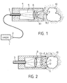
- the embodiment shown in Fig. 1 has a Q-switched laser 1 which is suitable for light pulses with a pulse duration of approximately 10 ns and an energy of 50 mJ.
- Light is understood to mean the entire optical spectral range of the electromagnetic waves, which ranges from the infrared to the ultraviolet.
- the laser radiation from the laser 1 is coupled into an optical fiber 3 via a coupling optic 2, the outlet-side end of which opens into a housing 4 shown in a greatly enlarged form.
- the divergent laser beam 5 emerging from the light guide 3 is focused on a point 7 by means of an optical system 6.
- This point 7 is also the first focal point of an ellipsoidal reflector 8, which is formed by the housing 4 and has a light inlet opening 8.1 and an outlet opening 8.2 for the reflected shock wave.
- This reflector 8 has the task of focusing shock waves which are generated at point 7 by reflection onto the second focus point 9 of the reflector.
- the reflector should be designed in such a way that the highest possible proportion of the wave energy generated in the first focus point is transmitted to the second focus point in the correct phase.
- Such reflectors are known for example from DE-OS 23 51 247 or DE-OS 32 41 026.
- the light guide 3 with the relatively narrow housing 4 is brought to the destruction of a solid deposit either through a natural body opening or through a narrow channel created in the vicinity of the deposit 10 so that the second focal point 9 either on the surface or just inside the deposit 10 lies.
- a cannula (not shown) is carried with the light guide, through which a rinsing liquid 14 is brought in the area between the reflector 8 and the body 10 to be destroyed becomes.
- the above-mentioned breakdown effect is then generated in this water-containing liquid 14 by means of a laser pulse and the resulting acoustic shock wave is directed via the reflector 8 onto the body to be destroyed.
- the fluid 14, which may also be gaseous, should both have the desired optical properties with regard to the breakdown effect and also allow the shock wave to be transmitted with as little loss as possible.
- Fig. 2 shows a device arranged at the end of the light guide 3 for generating a shock wave, in which the focusing optics 6 is followed by a pivotable about an axis 11 spherical reflector 12, the focal point 13 coincides with the focal point of the optics 6.
- the reflector 12 either consists entirely or only in an area 12.1 of a high-strength material which is transparent to the laser radiation, e.g. Glass ceramic.
- the outer edge of the reflector also serves as a stop for the body 10 to be destroyed and is so far advanced that when the body 10 comes into contact with its surface in the vicinity of the focal point 10.
- the exemplary embodiments shown show that the device enables exact application in the smallest space directly at the concrement.
Abstract
Description
Verfahren und Vorrichtung zur Zertrümmerung eines festen KörpersMethod and device for crushing a solid body
Die Erfindung betrifft ein Verfahren und eine Vorrichtung zur Zertrümmerung eines festen Körpers, welcher von einem Fluid umgeben ist, insbesondere zur Zertrümmerung von Konkrementen in Lebewesen, mittels eines über einen Lichtleiter geführten LichtimpulsesThe invention relates to a method and a device for crushing a solid body which is surrounded by a fluid, in particular for crushing concretions in living beings, by means of a light pulse conducted over a light guide
Verfahren und Vorrichtungen dieser Art sind in "Urologe" (1984) 23, S. 181 - 184 beschrieben. In diesem Artikel werden mehrere Methoden zur Zerstörung von Harnsteinen durch Laserstrahlung abgehandelt, wobei eine dieser Methoden darin besteht, daß ein Harnstein durch Bestrahlung mit Einzelimpulsen von 24 mJ bei 200 µs bis 20 J bei 10 ms bestrahlt wurden. Dabei wurden nach 1 bis 3 Impulsen regelmäßig Absprengungen von Teilchen des Steines beobachtet. In keinem Fall konnte eine vollständige Zerstörung des Steines erreicht werden. Eine Schockwelle, die zur Zerstörung der gesamten Kristallstruktur führen sollte, konnte mit dem gepulsten Laser nicht erzeugt werden.Methods and devices of this type are described in "Urologe" (1984) 23, pp. 181-184. In this article, several methods for the destruction of urinary stones by laser radiation are dealt with, one of these methods being that a urinary stone was irradiated by irradiation with single pulses of 24 mJ at 200 μs to 20 J at 10 ms. After 1 to 3 pulses, particles of the stone were regularly blasted off. In no case could the stone be completely destroyed. A shock wave that should lead to the destruction of the entire crystal structure could not be generated with the pulsed laser.
Bei einer anderen Methode wurde mit Hilfe eines gepulsten Lasers (Q-switched, Leistung 13,5 mJ bei 12 ns) ein Laserstrahl auf ein Ankopplungsmedium (Aluminiumfilm und Glasscheibe) geleitet und somit die Lichtenergie durch eine optomechanische Ankopplung in mechanische Energie verwandelt. Bei direktem Kontakt mit dem Stein führte der Laserimpuls zum Zerspringen des Steines. Bei diesem Verfahren wird allerdings die Energie ungerichtet abgegeben, wodurch außer dem Stein auch jedesmal das Ankopplungsmedium und der Lichtleiter zerstört wurden.In another method, a laser beam was directed onto a coupling medium (aluminum film and glass pane) with the aid of a pulsed laser (Q-switched, power 13.5 mJ at 12 ns) and the light energy was thus converted into mechanical energy by an optomechanical coupling. In direct contact with the stone, the laser pulse caused the stone to shatter. With this method, however, the energy is emitted in a non-directional manner, which means that in addition to the stone, the coupling medium and the light guide were also destroyed each time.
In dem oben erwähnten Artikel wird weiterhin die Vermutung ausgesprochen, daß eine Stoßwelle bei ausreichender Leistungsdichte des Laserimpulses auch direkt in dem, den Stein umgebenden Wasser erzeugt werden könnte. Hierbei wird auf ein ähnliches Prinzip bei der extrakorporalen Stoßwellenlithotrypsie verwiesen, bei dem eine hochgespannte Funkenentladung zur explosionsartigen Verdampfung von Wasser führt. Die dabei frei werdende Energie wird dabei durch einen ellipsoidförmigen Stoßwellenreflektor von außen durch den lebenden Körper auf den zu zertrümmernden Harnstein fokussiert.In the above-mentioned article, the assumption is further made that a shock wave could also be generated directly in the water surrounding the stone if the power density of the laser pulse is sufficient. Reference is made to a similar principle in extracorporeal shock wave lithotrypsy, in which a high-voltage spark discharge leads to the explosive evaporation of water. The energy released is focused by an ellipsoidal shock wave reflector from the outside through the living body onto the urinary stone to be crushed.
Insgesamt wird eine in vivo Anwendung von direkter Laserstrahlung zur Zertrümmerung von Harnsteinen aufgrund thermischer oder mechanischer Schäden des umgebenden lebenden Gewebes noch nicht als sinnvoll angesehen. Hier setzt nun die Erfindung ein, der die Aufgabe zugrundeliegt, ein Verfahren und eine Vorrichtung zur Zertrümmerung von festen Körpern mittels eines über einen Lichtleiter geführten Lichtimpulses zu schaffen, welche an schwer zugänglichen Stellen anwendbar sind und somit insbesondere zur Zertrümmerung von Konkrementen in Lebewesen geeignet ist.Overall, an in vivo application of direct laser radiation to break up urinary stones due to thermal or mechanical damage to the surrounding living tissue is not yet considered useful. This is where the invention begins, which is based on the object of creating a method and a device for the destruction of solid bodies by means of a light pulse guided over a light guide, which can be used in places which are difficult to access and are therefore particularly suitable for the destruction of concretions in living beings .
Die Erfindung wird durch ein Verfahren sowie durch eine Vorrichtung nach den kennzeichnenden Merkmalen der Ansprüche 1 und 5 gelöst. Die Erfindung macht sich die Erkenntnis zunutze, daß laserinduzierte Stoßwellen durch den sog. "Breakdown-Effekt" erzeugt werden können (Dissertation von Dipl.-Phys. Jürgen Munschau "Theoretische und experimentelle Untersuchungen zur Erzeugung, Ausbreitung und Anwendung laserinduzierter Stoßwellen", TU Berlin, Berlin 1981). Mit Breakdown wird dabei die starke Ionisation eines Mediums im Brennpunkt eines fokussierten Laserstrahles bezeichnet. Die dabei im Fokalbereich umgesetzte Energie steigt durch Kaskadenionisation etwa exponentiell mit der Zeit an. Infolge des Expansionsbestrebens des heißen Plasmas wächst der Druck, den das Plasma auf seine Umgebung ausübt, also ordentlich stark an. Diese Expansion erfolgt so rapide, daß auf das umgebende Medium ein Stoß ausgeübt wird, ähnlich wie bei einer Explosion. In größerer Entfernung von dem Plasmabereich geht die Stoßwelle, unabhängig von der ursprünglichen Form des Plasmabereichs, in eine Kugelwelle über. Der Breakdown-Schwellwert, also der Wert der Strahlungsintensität, bei der die Plasmasbildung einsetzt, ist von dem jeweiligen Fluid abhängig und beträgt beispielsweise in Luft unter Atmosphärendruck ca. 2 . 1014 W/m2 und bei destilliertem Wasser ca. 6,4 . 1013 W/m 2. Nähere Angaben zur Erzeugung laserinduzierter Stoßwellen, insbesondere zu den verwendeten Lasergeräten sowie zu dem Einfluß der Optik, können der obengenannten Dissertation entnommen werden.The invention is achieved by a method and by a device according to the characterizing features of
Im folgenden wird die Erfindung anhand zweier teilweise schematisch dargestellter Ausführungsbeispiele näher beschrieben. Es zeigen:
- Fig. 1 eine Einrichtung zur Zerstörung fester Ablagerungen im menschlichen Körper mit einer am Ende eines Lichtleiters angeordneten Einrichtung zur Erzeugung von Stoßwellen:
- Fig. 2 eine weitere Ausführungsform eines am Ende eines Lichtleiters angeordnete Einrichtung zur Erzeugung von Stoßwellen.
- 1 shows a device for destroying solid deposits in the human body with a device arranged at the end of a light guide for generating shock waves:
- Fig. 2 shows a further embodiment of a device arranged at the end of a light guide for generating shock waves.
Die in Fig. 1 dargestellte Ausführungsform weist einen Q-switched-Laser 1 auf, der geeignet ist, Lichtimpulse mit einer Pulsdauer von etwa 10 ns und einer Energie von 50 mJ auszusenden. Unter Licht wird dabei der gesamte optische Spektralbereich der elektromagnetischen Wellen verstanden, welcher vom Infraroten bis zum Ultravioletten reicht. Die Laserstrahlung aus dem Laser 1 wird über eine Einkoppeloptik 2 in eine Lichtleitfaser 3 eingekoppelt, deren austrittsseitiges Ende in ein stark vergrößert dargestelltes Gehäuse 4 mündet. Der divergent aus dem Lichtleiter 3 austretende Laserstrahl 5 wird mittels einer Optik 6 auf einen Punkt 7 fokussiert. Dieser Punkt 7 ist gleichzeitig der erste Fokuspunkt eines ellipsoidförmigen Reflektors 8, welcher durch das Gehäuse 4 gebildet wird und eine Lichteintrittsöffnung 8.1 sowie eine Austrittsöffnung 8.2 für die reflektierte Stoßwelle aufweist. Dieser Reflektor 8 hat die Aufgabe, Stoßwellen, welche im Punkt 7 erzeugt werden, durch Reflexion auf den zweiten Fokuspunkt 9 des Reflektors zu fokussieren. Der Reflektor soll so beschaffen sein, daß ein möglichst hoher Anteil der im ersten Fokuspunkt erzeugten Wellenenergie möglichst phasenrichtig in den zweiten Fokuspunkt übertragen wird. Derartige Reflektoren sind beispielsweise aus der DE-OS 23 51 247 oder DE-OS 32 41 026 bekannt.The embodiment shown in Fig. 1 has a Q-switched
Der Lichtleiter 3 mit dem relativ schmalen Gehäuse 4 wird zur Zerstörung einer festen Ablagerung entweder durch eine natürliche Körperöffnung oder durch einen geschaffenen schmalen Kanal in die Nähe der Ablagerung 10 so gebracht, daß der zweite Brennpunkt 9 entweder auf der Oberfläche oder knapp innerhalb der Ablagerung 10 liegt. In der Regel wird mit dem Lichtleiter eine nicht dargestellte Kanüle mitgeführt, über die eine Spülflüssigkeit 14 in dem Bereich zwischen dem Reflektor 8 und dem zu zerstörenden Körper 10 gebracht wird. In dieser wasserhaltigen Flüssigkeit 14 wird dann mittels eines Laserimpulses der oben erwähnte Breakdown-Effekt erzeugt und die dabei entstehende akustische Stoßwelle über den Reflektor 8 auf den zu zerstörenden Körper ge- richtet. Das Fluid 14, welches ggf. auch gasförmig sein kann, sollte sowohl die gewünschten optischen Eigen- schaften hinsichtlich des Breakdown-Effektes aufweisen, als auch eine möglichst verlustarme Übertragung der entstehenden Stoßwelle erlauben.The
Fig. 2 zeigt eine am Ende des Lichtleiters 3 angeordnete Einrichtung zur Erzeugung einer Stoßwelle, bei der sich an die Fokussieroptik 6 ein um eine Achse 11 schwenkbarer Kugelreflektor 12 anschließt, dessen Brennpunkt 13 mit dem Brennpunkt der Optik 6 zusammenfällt. Der Reflektor 12 besteht entweder vollständig oder nur in einem Bereich 12.1 aus einem für die Laserstrahlung transparenten, hochfesten Material, z.B. Glaskeramik. Der äußere Rand des Reflektors dient gleichzeitig als Anschlag für den zu zerstörenden Körper 10 und ist so weit vorgezogen, daß bei Berührung der Körper 10 mit seiner Oberfläche in der Nähe des Brennpunktes 10 liegt. Die dargestellten Ausführungsbeispiele zeigen, daß mit der Einrichtung eine exakte Applikation auf kleinstem Raum direkt am Konkrement möglich ist.Fig. 2 shows a device arranged at the end of the
Weitere Ausführungsformen, insbesondere Variationen der Ausgestaltungen des Reflektors für die Fokussierung der akustischen Stoßwellen sind ,abhängig vom jeweiligen Verwendungszweck, möglich.Further embodiments, in particular variations of the configurations of the reflector for focusing the acoustic shock waves, are possible, depending on the respective intended use.
Verfahren und Vorrichtung zur Zertrümmerung eines festen KörpersMethod and device for crushing a solid body
Claims (10)
gekennzeichnet durch
marked by
Applications Claiming Priority (2)
| Application Number | Priority Date | Filing Date | Title |
|---|---|---|---|
| DE19853506249 DE3506249A1 (en) | 1985-02-22 | 1985-02-22 | METHOD AND DEVICE FOR SMASHING A SOLID BODY |
| DE3506249 | 1985-02-22 |
Publications (2)
| Publication Number | Publication Date |
|---|---|
| EP0192833A2 true EP0192833A2 (en) | 1986-09-03 |
| EP0192833A3 EP0192833A3 (en) | 1988-10-12 |
Family
ID=6263304
Family Applications (1)
| Application Number | Title | Priority Date | Filing Date |
|---|---|---|---|
| EP85115446A Withdrawn EP0192833A3 (en) | 1985-02-22 | 1985-12-05 | Method and device for the disintegration of a concretion |
Country Status (3)
| Country | Link |
|---|---|
| EP (1) | EP0192833A3 (en) |
| JP (1) | JPS61193653A (en) |
| DE (1) | DE3506249A1 (en) |
Cited By (15)
| Publication number | Priority date | Publication date | Assignee | Title |
|---|---|---|---|---|
| EP0268019A1 (en) * | 1986-11-13 | 1988-05-25 | Messerschmitt-Bölkow-Blohm Gesellschaft mit beschränkter Haftung | Apparatus for disintegrating a fluid-suspended solid body |
| FR2651333A1 (en) * | 1989-01-13 | 1991-03-01 | Fiz Tekhn I Ime | DEVICE FOR FORMING FOCUSED SHOCK WAVES. |
| EP0454312A2 (en) * | 1990-04-06 | 1991-10-30 | Aurora Laser Inc. | Method and apparatus for laser lithotripsy |
| WO1995024867A1 (en) * | 1994-03-15 | 1995-09-21 | Dodick Jack M | Laser energy concentration in laser powered surgical instrument |
| WO1998033623A1 (en) * | 1997-02-05 | 1998-08-06 | Biolase Technology, Inc. | Electromagnetically induced cutter with shaped fluid particles |
| US5968037A (en) * | 1995-08-31 | 1999-10-19 | Biolase Technology, Inc. | User programmable combination of atomized particles for electromagnetically induced cutting |
| US6106546A (en) * | 1988-10-11 | 2000-08-22 | The General Hospital Corporation | Inducing vasodilation |
| US6288499B1 (en) | 1997-06-12 | 2001-09-11 | Biolase Technology, Inc. | Electromagnetic energy distributions for electromagnetically induced mechanical cutting |
| EP1634656A1 (en) * | 2004-09-13 | 2006-03-15 | Nederlandse Organisatie voor toegepast-natuurwetenschappelijk Onderzoek TNO | Ultrasound lumen cleaning technique |
| US7320594B1 (en) | 1995-08-31 | 2008-01-22 | Biolase Technology, Inc. | Fluid and laser system |
| US7957440B2 (en) | 2004-07-27 | 2011-06-07 | Biolase Technology, Inc. | Dual pulse-width medical laser |
| US8033825B2 (en) | 1995-08-31 | 2011-10-11 | Biolase Technology, Inc. | Fluid and pulsed energy output system |
| US20160081749A1 (en) * | 2014-09-24 | 2016-03-24 | Ams Research, Llc | Surgical laser systems and laser lithotripsy techniques |
| CN112153947A (en) * | 2018-03-29 | 2020-12-29 | 声波创新株式会社 | Shock wave generation device and shock wave ablation system |
| US20220370130A1 (en) * | 2014-09-24 | 2022-11-24 | Boston Scientific Scimed, Inc. | Surgical laser systems and laser lithotripsy techniques |
Families Citing this family (10)
| Publication number | Priority date | Publication date | Assignee | Title |
|---|---|---|---|---|
| JPS62337A (en) * | 1985-06-26 | 1987-01-06 | 八千代田工業株式会社 | High voltage generator by submerged shock wave |
| DE3727003A1 (en) * | 1986-08-13 | 1988-02-25 | Messerschmitt Boelkow Blohm | Application part for a rigid or flexible endoscope |
| US4838246A (en) * | 1986-08-13 | 1989-06-13 | Messerschmitt-Bolkow-Blohm Gmbh | Application part for an endoscope |
| DE3728814A1 (en) * | 1987-08-28 | 1989-03-30 | Lentia Gmbh | SOLUTION FOR USE AS A RINSING LIQUID IN THE DESTRUCTION OF NON-BODY DEPOSITS IN HUMAN AND ANIMAL TISSUES OR BODIES |
| DE3840126A1 (en) * | 1988-11-29 | 1990-05-31 | Messerschmitt Boelkow Blohm | Protection device for a fibre-coupled laser lithotriptor |
| DE3842916C1 (en) * | 1988-12-21 | 1990-02-01 | Messerschmitt-Boelkow-Blohm Gmbh, 8012 Ottobrunn, De | |
| US4955385A (en) * | 1989-02-06 | 1990-09-11 | C. R. Bard, Inc. | Ultrasound targeting system for shockwave lithotripsy |
| DE3933613C2 (en) * | 1989-10-07 | 1998-10-08 | Laser & Med Tech Gmbh | Device for generating laser-induced shock waves |
| US5254112A (en) * | 1990-10-29 | 1993-10-19 | C. R. Bard, Inc. | Device for use in laser angioplasty |
| JP2010119446A (en) | 2008-11-17 | 2010-06-03 | Omron Healthcare Co Ltd | Blood pressure measuring apparatus |
Citations (4)
| Publication number | Priority date | Publication date | Assignee | Title |
|---|---|---|---|---|
| DE2412690A1 (en) * | 1973-03-23 | 1974-10-17 | Wolf Gmbh Richard | DEVICE FOR THE DESTRUCTION OF STONES IN THE URINE TRAIL, ESPECIALLY OF URIDAL AND KIDNEY STONES |
| DE2538960A1 (en) * | 1975-09-02 | 1977-04-07 | Dornier System Gmbh | Therapeutic destruction of concretions by impulse laser - uses elliptical focussing chamber with shock waves produced at focal point |
| EP0062390A1 (en) * | 1981-04-08 | 1982-10-13 | N.V. Optische Industrie "De Oude Delft" | Scanner for scanning an object by means of ultrasonic radiation |
| WO1985003631A1 (en) * | 1984-02-22 | 1985-08-29 | Washington Research Foundation | Apparatus for the noninvasive shock fragmentation of renal calculi |
-
1985
- 1985-02-22 DE DE19853506249 patent/DE3506249A1/en active Granted
- 1985-12-05 EP EP85115446A patent/EP0192833A3/en not_active Withdrawn
-
1986
- 1986-02-21 JP JP61035414A patent/JPS61193653A/en active Pending
Patent Citations (4)
| Publication number | Priority date | Publication date | Assignee | Title |
|---|---|---|---|---|
| DE2412690A1 (en) * | 1973-03-23 | 1974-10-17 | Wolf Gmbh Richard | DEVICE FOR THE DESTRUCTION OF STONES IN THE URINE TRAIL, ESPECIALLY OF URIDAL AND KIDNEY STONES |
| DE2538960A1 (en) * | 1975-09-02 | 1977-04-07 | Dornier System Gmbh | Therapeutic destruction of concretions by impulse laser - uses elliptical focussing chamber with shock waves produced at focal point |
| EP0062390A1 (en) * | 1981-04-08 | 1982-10-13 | N.V. Optische Industrie "De Oude Delft" | Scanner for scanning an object by means of ultrasonic radiation |
| WO1985003631A1 (en) * | 1984-02-22 | 1985-08-29 | Washington Research Foundation | Apparatus for the noninvasive shock fragmentation of renal calculi |
Cited By (20)
| Publication number | Priority date | Publication date | Assignee | Title |
|---|---|---|---|---|
| EP0268019A1 (en) * | 1986-11-13 | 1988-05-25 | Messerschmitt-Bölkow-Blohm Gesellschaft mit beschränkter Haftung | Apparatus for disintegrating a fluid-suspended solid body |
| US6106546A (en) * | 1988-10-11 | 2000-08-22 | The General Hospital Corporation | Inducing vasodilation |
| FR2651333A1 (en) * | 1989-01-13 | 1991-03-01 | Fiz Tekhn I Ime | DEVICE FOR FORMING FOCUSED SHOCK WAVES. |
| EP0454312A2 (en) * | 1990-04-06 | 1991-10-30 | Aurora Laser Inc. | Method and apparatus for laser lithotripsy |
| EP0454312A3 (en) * | 1990-04-06 | 1991-11-06 | Aurora Laser Inc. | Method and apparatus for laser lithotripsy |
| WO1995024867A1 (en) * | 1994-03-15 | 1995-09-21 | Dodick Jack M | Laser energy concentration in laser powered surgical instrument |
| US7320594B1 (en) | 1995-08-31 | 2008-01-22 | Biolase Technology, Inc. | Fluid and laser system |
| US5968037A (en) * | 1995-08-31 | 1999-10-19 | Biolase Technology, Inc. | User programmable combination of atomized particles for electromagnetically induced cutting |
| US8033825B2 (en) | 1995-08-31 | 2011-10-11 | Biolase Technology, Inc. | Fluid and pulsed energy output system |
| US6610053B1 (en) | 1995-08-31 | 2003-08-26 | Biolase Technology, Inc. | Methods of using atomized particles for electromagnetically induced cutting |
| US7696466B2 (en) | 1995-08-31 | 2010-04-13 | Biolase Technology, Inc. | Electromagnetic energy distributions for electromagnetically induced mechanical cutting |
| WO1998033623A1 (en) * | 1997-02-05 | 1998-08-06 | Biolase Technology, Inc. | Electromagnetically induced cutter with shaped fluid particles |
| US6288499B1 (en) | 1997-06-12 | 2001-09-11 | Biolase Technology, Inc. | Electromagnetic energy distributions for electromagnetically induced mechanical cutting |
| US7957440B2 (en) | 2004-07-27 | 2011-06-07 | Biolase Technology, Inc. | Dual pulse-width medical laser |
| WO2006031106A1 (en) * | 2004-09-13 | 2006-03-23 | Nederlandse Organisatie Voor Toegepast- Natuurwetenschappelijk Onderzoek Tno | Ultrasound lumen cleaning technique |
| EP1634656A1 (en) * | 2004-09-13 | 2006-03-15 | Nederlandse Organisatie voor toegepast-natuurwetenschappelijk Onderzoek TNO | Ultrasound lumen cleaning technique |
| US20160081749A1 (en) * | 2014-09-24 | 2016-03-24 | Ams Research, Llc | Surgical laser systems and laser lithotripsy techniques |
| US20220370130A1 (en) * | 2014-09-24 | 2022-11-24 | Boston Scientific Scimed, Inc. | Surgical laser systems and laser lithotripsy techniques |
| CN112153947A (en) * | 2018-03-29 | 2020-12-29 | 声波创新株式会社 | Shock wave generation device and shock wave ablation system |
| EP3777747A4 (en) * | 2018-03-29 | 2022-01-05 | Sound Wave Innovation Co., Ltd. | Shock wave generating device, and shock wave ablation system |
Also Published As
| Publication number | Publication date |
|---|---|
| JPS61193653A (en) | 1986-08-28 |
| DE3506249A1 (en) | 1986-08-28 |
| EP0192833A3 (en) | 1988-10-12 |
| DE3506249C2 (en) | 1988-05-26 |
Similar Documents
| Publication | Publication Date | Title |
|---|---|---|
| EP0192833A2 (en) | Method and device for the disintegration of a concretion | |
| EP0143185B1 (en) | Dual-purpose apparatus for the diagnosis and therapy of the eye | |
| DE2538960C2 (en) | Device for the contactless smashing of calculus in a living being | |
| DE3736953C2 (en) | DEVICE FOR SMASHING A SOLID BODY SURROUNDED BY A FLUID | |
| DE3933613C2 (en) | Device for generating laser-induced shock waves | |
| DE10140064A1 (en) | Cosmetic or medical treatment of the skin using ultrasound waves, e.g. permanent hair removal using a simple device comprising a mechanical oscillator and focussing lenses with a spacer for varying the distance to the skin | |
| DE2810879A1 (en) | DEVICE AND METHOD FOR CAUTERIZING BLOOD VESSELS AND OTHER BIOLOGICAL TISSUE | |
| WO2002076355A2 (en) | Method for treatment and diagnosis of eye tissues | |
| DE4228993A1 (en) | Surgical laser tool with easy manipulation, to effect haemostasis - has heated probe which emits laser beam and has working section with hydroxyl gp.-contg. material | |
| EP1537841A2 (en) | Method and device for treating opaqueness and/or hardening of a closed eye | |
| EP0423431A2 (en) | Surgical laser | |
| DE3733489A1 (en) | METHOD AND DEVICE FOR PROCESSING MATERIALS WITH THE AID OF A LASER | |
| Schmidt-Kloiber et al. | Laserinduced Shock-Wave Lithotripsy (LISL)-Die Laserinduzierte Stoßwellenlithotripsie (LISL) | |
| EP0111047A1 (en) | Apparatus to generate a succession of impulse-shock wave pulses | |
| EP0402433B1 (en) | Device for breaking up a solid body surrounded by a fluid | |
| CH672983A5 (en) | ||
| DE3840126C2 (en) | ||
| DE3617019A1 (en) | Catheter to dissolve atheromatous plaque - with distal deflector for laser beam to prevent vessel perforation | |
| DE3600713C2 (en) | ||
| WO2018189080A1 (en) | Device and method for laser-based separation of a transparent, brittle workpiece | |
| EP0233479B1 (en) | Limitating device for the maximum radiant intensity | |
| DE10148783B4 (en) | Method for the non-invasive optical processing of tissues of the eye and for its diagnosis and apparatus for carrying out these methods | |
| EP0311658B1 (en) | Device for treating tissues with laser | |
| DE3936716A1 (en) | Device for altering material structure using pulsed light beam - coagulation o biological tissues is produced in spatially limited region by using pulsing laser light beam with pref. light strength | |
| DE102005017724A1 (en) | Focusing device for a device for generating shockwaves |
Legal Events
| Date | Code | Title | Description |
|---|---|---|---|
| PUAI | Public reference made under article 153(3) epc to a published international application that has entered the european phase |
Free format text: ORIGINAL CODE: 0009012 |
|
| AK | Designated contracting states |
Kind code of ref document: A2 Designated state(s): AT BE CH DE FR GB IT LI LU NL SE |
|
| PUAL | Search report despatched |
Free format text: ORIGINAL CODE: 0009013 |
|
| AK | Designated contracting states |
Kind code of ref document: A3 Designated state(s): AT BE CH DE FR GB IT LI LU NL SE |
|
| 17P | Request for examination filed |
Effective date: 19890410 |
|
| 17Q | First examination report despatched |
Effective date: 19891026 |
|
| STAA | Information on the status of an ep patent application or granted ep patent |
Free format text: STATUS: THE APPLICATION HAS BEEN WITHDRAWN |
|
| 18W | Application withdrawn |
Withdrawal date: 19910506 |
|
| RIN1 | Information on inventor provided before grant (corrected) |
Inventor name: FRANK, FRANK, DR. Inventor name: HESSEL, STEFAN, DR. Inventor name: HAHN, ANDREAS Inventor name: WONDRAZEK, FRITZ, DR. |