EP0193759A1 - Active display matrix addressable without crossed lines on any one substrate and method of using the same - Google Patents
Active display matrix addressable without crossed lines on any one substrate and method of using the same Download PDFInfo
- Publication number
- EP0193759A1 EP0193759A1 EP86101810A EP86101810A EP0193759A1 EP 0193759 A1 EP0193759 A1 EP 0193759A1 EP 86101810 A EP86101810 A EP 86101810A EP 86101810 A EP86101810 A EP 86101810A EP 0193759 A1 EP0193759 A1 EP 0193759A1
- Authority
- EP
- European Patent Office
- Prior art keywords
- pixel
- voltage
- control
- electrodes
- further characterized
- Prior art date
- Legal status (The legal status is an assumption and is not a legal conclusion. Google has not performed a legal analysis and makes no representation as to the accuracy of the status listed.)
- Granted
Links
Images


Classifications
-
- G—PHYSICS
- G02—OPTICS
- G02F—OPTICAL DEVICES OR ARRANGEMENTS FOR THE CONTROL OF LIGHT BY MODIFICATION OF THE OPTICAL PROPERTIES OF THE MEDIA OF THE ELEMENTS INVOLVED THEREIN; NON-LINEAR OPTICS; FREQUENCY-CHANGING OF LIGHT; OPTICAL LOGIC ELEMENTS; OPTICAL ANALOGUE/DIGITAL CONVERTERS
- G02F1/00—Devices or arrangements for the control of the intensity, colour, phase, polarisation or direction of light arriving from an independent light source, e.g. switching, gating or modulating; Non-linear optics
- G02F1/01—Devices or arrangements for the control of the intensity, colour, phase, polarisation or direction of light arriving from an independent light source, e.g. switching, gating or modulating; Non-linear optics for the control of the intensity, phase, polarisation or colour
- G02F1/13—Devices or arrangements for the control of the intensity, colour, phase, polarisation or direction of light arriving from an independent light source, e.g. switching, gating or modulating; Non-linear optics for the control of the intensity, phase, polarisation or colour based on liquid crystals, e.g. single liquid crystal display cells
- G02F1/133—Constructional arrangements; Operation of liquid crystal cells; Circuit arrangements
- G02F1/136—Liquid crystal cells structurally associated with a semi-conducting layer or substrate, e.g. cells forming part of an integrated circuit
- G02F1/1362—Active matrix addressed cells
- G02F1/1368—Active matrix addressed cells in which the switching element is a three-electrode device
-
- G—PHYSICS
- G02—OPTICS
- G02F—OPTICAL DEVICES OR ARRANGEMENTS FOR THE CONTROL OF LIGHT BY MODIFICATION OF THE OPTICAL PROPERTIES OF THE MEDIA OF THE ELEMENTS INVOLVED THEREIN; NON-LINEAR OPTICS; FREQUENCY-CHANGING OF LIGHT; OPTICAL LOGIC ELEMENTS; OPTICAL ANALOGUE/DIGITAL CONVERTERS
- G02F1/00—Devices or arrangements for the control of the intensity, colour, phase, polarisation or direction of light arriving from an independent light source, e.g. switching, gating or modulating; Non-linear optics
- G02F1/01—Devices or arrangements for the control of the intensity, colour, phase, polarisation or direction of light arriving from an independent light source, e.g. switching, gating or modulating; Non-linear optics for the control of the intensity, phase, polarisation or colour
- G02F1/13—Devices or arrangements for the control of the intensity, colour, phase, polarisation or direction of light arriving from an independent light source, e.g. switching, gating or modulating; Non-linear optics for the control of the intensity, phase, polarisation or colour based on liquid crystals, e.g. single liquid crystal display cells
- G02F1/133—Constructional arrangements; Operation of liquid crystal cells; Circuit arrangements
- G02F1/136—Liquid crystal cells structurally associated with a semi-conducting layer or substrate, e.g. cells forming part of an integrated circuit
- G02F1/1362—Active matrix addressed cells
- G02F1/13624—Active matrix addressed cells having more than one switching element per pixel
-
- G—PHYSICS
- G09—EDUCATION; CRYPTOGRAPHY; DISPLAY; ADVERTISING; SEALS
- G09G—ARRANGEMENTS OR CIRCUITS FOR CONTROL OF INDICATING DEVICES USING STATIC MEANS TO PRESENT VARIABLE INFORMATION
- G09G3/00—Control arrangements or circuits, of interest only in connection with visual indicators other than cathode-ray tubes
- G09G3/20—Control arrangements or circuits, of interest only in connection with visual indicators other than cathode-ray tubes for presentation of an assembly of a number of characters, e.g. a page, by composing the assembly by combination of individual elements arranged in a matrix no fixed position being assigned to or needed to be assigned to the individual characters or partial characters
- G09G3/34—Control arrangements or circuits, of interest only in connection with visual indicators other than cathode-ray tubes for presentation of an assembly of a number of characters, e.g. a page, by composing the assembly by combination of individual elements arranged in a matrix no fixed position being assigned to or needed to be assigned to the individual characters or partial characters by control of light from an independent source
- G09G3/36—Control arrangements or circuits, of interest only in connection with visual indicators other than cathode-ray tubes for presentation of an assembly of a number of characters, e.g. a page, by composing the assembly by combination of individual elements arranged in a matrix no fixed position being assigned to or needed to be assigned to the individual characters or partial characters by control of light from an independent source using liquid crystals
- G09G3/3611—Control of matrices with row and column drivers
- G09G3/3648—Control of matrices with row and column drivers using an active matrix
- G09G3/3659—Control of matrices with row and column drivers using an active matrix the addressing of the pixel involving the control of two or more scan electrodes or two or more data electrodes, e.g. pixel voltage dependant on signal of two data electrodes
-
- G—PHYSICS
- G02—OPTICS
- G02F—OPTICAL DEVICES OR ARRANGEMENTS FOR THE CONTROL OF LIGHT BY MODIFICATION OF THE OPTICAL PROPERTIES OF THE MEDIA OF THE ELEMENTS INVOLVED THEREIN; NON-LINEAR OPTICS; FREQUENCY-CHANGING OF LIGHT; OPTICAL LOGIC ELEMENTS; OPTICAL ANALOGUE/DIGITAL CONVERTERS
- G02F2201/00—Constructional arrangements not provided for in groups G02F1/00 - G02F7/00
- G02F2201/12—Constructional arrangements not provided for in groups G02F1/00 - G02F7/00 electrode
- G02F2201/122—Constructional arrangements not provided for in groups G02F1/00 - G02F7/00 electrode having a particular pattern
-
- G—PHYSICS
- G09—EDUCATION; CRYPTOGRAPHY; DISPLAY; ADVERTISING; SEALS
- G09G—ARRANGEMENTS OR CIRCUITS FOR CONTROL OF INDICATING DEVICES USING STATIC MEANS TO PRESENT VARIABLE INFORMATION
- G09G2330/00—Aspects of power supply; Aspects of display protection and defect management
- G09G2330/08—Fault-tolerant or redundant circuits, or circuits in which repair of defects is prepared
-
- G—PHYSICS
- G09—EDUCATION; CRYPTOGRAPHY; DISPLAY; ADVERTISING; SEALS
- G09G—ARRANGEMENTS OR CIRCUITS FOR CONTROL OF INDICATING DEVICES USING STATIC MEANS TO PRESENT VARIABLE INFORMATION
- G09G3/00—Control arrangements or circuits, of interest only in connection with visual indicators other than cathode-ray tubes
- G09G3/20—Control arrangements or circuits, of interest only in connection with visual indicators other than cathode-ray tubes for presentation of an assembly of a number of characters, e.g. a page, by composing the assembly by combination of individual elements arranged in a matrix no fixed position being assigned to or needed to be assigned to the individual characters or partial characters
- G09G3/2007—Display of intermediate tones
- G09G3/2011—Display of intermediate tones by amplitude modulation
Definitions
- the present invention relates generally to light influencing displays and more particularly to active matrix displays in which each display element is controlled by a separate three terminal control device, such as a transistor, and to methods of using the same.
- Light influencing displays are well known in the prior art. They include liquid crystal, electroluminescent, and electrochromic displays.
- pixels there to be a plurality of individually addressable picture elements, called pixels, each having a separate pair of opposing pixel electrodes, with light influencing material between them. Voltages are selectively applied to the electrode pairs, causing the light influencing material between them to emit light or change optical density.
- these opposing pixel electrodes are located on opposing substrates, such as opposing glass plates, with the light influencing material, such as liquid crystal material, located between the substrates.
- each of the x and y lines is usually directly connected, without. intervening electronic devices, to the bottom or top pixel electrodes in its associated row or column.
- the pixels of such an array are driven sequentially in a scanning process in which each row is selected successively, and, during the selection of each row, each column is selected successively, causing the pixels of each row to be scanned in sequential order.
- the circuitry decides whether that pixel is to be turned on or off by controlling the amplitude of the voltage applied across the pixel.
- each of the rows is selected in succession, and during the selection of each row all of the column lines are driven in parallel with individually selected voltages, turning each pixel in the row to a desired state, either "on” or "off".
- Such multiplexing scanning schemes in which the pixels are driven directly by their x and y address lines without intervening electronic devices work well for relatively small arrays. But as array size grows, the amount of time for the application of a voltage to a given pixel, or row of pixels, decreases. As a result, the percentage of time during each scanning cycle that a given pixel has a voltage applied across it decreases, thereby decreasing the average contrast between its "on” state and its "off” state. For this reason large multiplexed displays tend to produce images with poor contrast, making such displays difficult to read.
- active display matrixes instead of multiplexed displays.
- each of the pixels has associated with it a non-linear electronic device which acts as a switch.
- This switch enables current to flow to or from the pixel during the brief period when the pixel is selected, enabling it to rapidly change state from “off” to "on”, or vice versa, but it tends to prevent current flow to or from the pixel when.it is not selected, so the charge placed on the pixel during its brief selection period is substantially maintained during the rest of the scanning cycle .
- the pixel tends to maintain its "on” or its "off” state during the entire scanning cycle, greatly increasing the contrast and readability of the display.
- a three terminal control device is one that has two current path electrodes and a control electrode, with the effective resistance between the two current path electrodes being controlled as a function of a signal supplied to the control electrode.
- the voltage applied to the gate electrode controls the amount of current which flows between the source and the drain of the transistor.
- the three terminal devices are usually arranged on one substrate of the display, with one of their current path electrodes connected to an electrode of their associated pixel.
- crossing x and y lines are also placed on the substrate to enable each three terminal device and its associated pixel to be individually addressed.
- One of the sets of the address lines for example, the x lines, are connected to the control electrodes of the three terminal devices, with each x line being connected to each of the control electrodes in its associated row of pixels.
- the other set of address lines, the y lines are connected to one of the current path electrodes of the control devices; with each y line being connected to a current path electrode associated with each pixel in its column.
- All the pixel electrodes on the display's other substrate are usually connected to a common voltage, such as ground.
- a given pixel is selected by applying a proper voltage between the x line connected to the control electrode of its three terminal device and the y line connected to the current path electrode of its three terminal device.
- the three terminal devices are thin film field effect transistors
- the source of each transistor is connected to a y line and the gate of each transistor is connected to an x line.
- a selected transistor is turned on or off by providing the desired voltages between the x line connected to its gate and the y line connected to its source.
- the present invention relates to a light influencing display having a plurality of pixels, each with a first electrode connected to a preselected voltage through a switchable deposited semiconductor control device and each with an opposing second electrode.
- the invention provides means for turning on each control device of a first selected group of the pixels, so the first electrode of each pixel in that group is connected to a preselected voltage. It also provides means for supplying a data voltage to each second electrode in a second selected group of the pixels.
- a pixel which belongs to both groups is addressed by having a selected voltage applied between its first and second electrodes.
- the present invention relates to a light influencing display which has a plurality of pixels, each including a first electrode formed on a first surface and an opposing, second electrode formed on a second surface.
- the plurality of pixels is divided into pixel groups, each consisting of a separate plurality of pixels.
- a separate three terminal control device is formed of deposited semiconductor material on the first surface in association with each pixel.
- Each of the control devices has two current path terminals and a control terminal which controls the conductivity between them.
- a first of each control devices' current path terminals is connected to the first electrode of its associated pixel.
- the display further includes a separate voltage supply lead formed on the first surface in association with each pixel group, with each such voltage supply lead being connected to the second current path terminal associated with its pixel group.
- a conductive control lead is also formed on the first surface in association with each pixel group, with each such control lead being connected to the control terminals associated with its pixel group.
- a plurality of conductive data leads is formed on the second surface, with a different data lead being electrically connected to each second electrode of a given pixel group, and with individual data leads being connected to at least one second pixel electrode in each of a plurality of pixel groups.
- the first and second insulative surfaces are the surfaces of two opposing substrates formed of a material such as glass, and a light influencing display material, such as liquid crystal material, is placed between the first and second electrodes of each pixel.
- the control devices associated with each pixel are transistors, such as thin film field effect transistors having channel regions formed of a deposited semiconductor material, such as an amorphous alloy of silicon, including hydrogen and/or fluorine as density of state reducing elements.
- each first pixel electrode has two separate three terminal control devices formed in association with it to provide redundancy, and at least one of the control devices has a laser blowable fuse connected to one or two of its electrodes so as to enable that controT device to be removed from effective operation.
- the voltage supply lead associated with one pixel group functions as a control lead associated with another pixel group.
- the pixels in each pixel group are arranged in a row and the voltage supply and control leads associated with each pixel row form two non-crossing parallel conductive lines extending in the direction of that row.
- the pixels are arranged in an x - y array so that each pixel belongs to both a pixel row and a pixel column.
- the data lead is connected to the second pixel electrode of all the pixels in a given pixel column, so that by selectively supplying the proper voltage through a control lead associated with a selected pixel row and by supplying a voltage through a data lead connected to a selected pixel column, the pixel at the intersection of the selected row and column has a voltage applied across it.
- each pixel row has associated with it one voltage supply lead and one control lead in addition to the voltage supply and control leads of any other pixel row, so that each additional row requires two additional conductive leads.
- the voltage supply lead associated with one pixel row also functions as the control lead associated with an adjacent pixel row, so that each additional row only requires one additional conductive lead.
- the present invention also relates to subassemblies for use in light influencing displays of the type described above.
- Such subassemblies comprise the elements formed on the first insulative surface in the embodiments of the invention described above.
- the present invention also relates to the method of supplying a voltage to a selected pixel from among a plurality of pixels divided into groups.
- the method is applicable in cases in which each pixel has a first and a second electrode and has a separate three terminal control device of the type described above, with a first of the control device's current path terminals connected to the pixel's first electrode.
- the method of the present invention comprises supplying preselected voltages to the second current path terminals of the control devices associated with each pixel.
- the method further includes supplying a data voltage through a selected data lead to a second pixel electrode in each of the pixel groups, including the second pixel electrode of the pixel to be selected.
- It also includes supplying an "on" signal to each of the control terminals of the control devices associated with the pixel group including the selected pixel, so as to turn on the conductivity between the current path terminals of its control devices, thus effectively connecting the first electrode of the selected pixel to a given preselected voltage.
- the method also includes supplying an "off" signal to each of the control terminals of the control devices associated with other, non-selected, pixel groups, so as to turn off the conductivity between the current path terminals of their control devices. As a result, a selected voltage is applied across the selected pixel, but not across pixels in the non-selected pixel groups.
- a plurality of separately selectable data voltages are supplied in parallel through a plurality of data leads, with each selected voltage being supplied to one second pixel electrode in each pixel group.
- each selected voltage being supplied to one second pixel electrode in each pixel group.
- the pixels are arranged in an x - y array in which each pixel group forms a row in the array, and each pixel, besides being in a pixel row, is also in a pixel column.
- the supplying of a voltage through a selected data lead includes supplying such a voltage through a data lead to each second electrode of each pixel belonging to a given pixel column.
- a separate voltage supply lead is used to supply the preselected voltages to the second current path terminals associated with each pixel group.
- a separate control lead is used to supply the "on” and “off” signals to the control terminals associated with each pixel group.
- the same conductive lead which is used as the control lead to supply the "on” and “off” signals to the control terminals associated with 0 ⁇ e pixel group is also used at other times as the voltage supply lead to supply a certain preselected voltage to the second current path terminals associated with another pixel group when that other pixel group is the selected pixel group.
- the method of the present invention has two alternate embodiments for use with liquid crystal displays for periodically reversing the polarity of the voltages supplied across the pixels of such displays, so as to reduce the deterioration of such pixels which would result from a prolonged net direct current flow across them.
- the preselected voltage supplied to the second current path terminals associated with the selected pixel group is held constant and the polarity of the data voltages applied to the second pixel electrodes is periodically reversed.
- the preselected voltage supplied to the second current path terminals associated with the selected pixel groups is periodically changed between a more positive voltage and a more negative voltage.
- the data voltages supplied to the second pixel electrodes are substantially limited to voltages below the preselected voltage when the preselected voltage is at the more positive level, and are substantially limited to voltages above the preselected voltage when the preselected voltage is at the more negative level.
- the preselected voltages are supplied to the second current path terminals of all the pixel groups in common.
- control devices are thin film field effect transistors and the current path terminals are sources and drains of such transistors, and the control terminals are the gates of such transistors.
- the "on" signal supplied to the gate electrodes of the selected pixel group is a voltage sufficiently higher than the preselected voltage supplied to the source electrodes of the selected group so as to turn the transistors of the selected group "on”.
- the "off" signal supplied to the gate electrodes associated with the non-selected pixel groups is sufficiently low to keep the transistors of those non-selected pixel groups "off”.
- this "off" signal is a voltage which is sufficiently low to keep the transistors of the non-selected pixel groups “off", even when the voltage on the first pixel electrode connected to the first current path terminals of those transistors is less than the preselected voltage supplied to the source electrodes of such transistors by twice the largest data voltage applied across the pixels.
- a first object of the invention is to provide a light influencing display including first and second surfaces, a plurality of pixels arranged in rows and columns, each including a first electrode formed on the first surface, an opposing second electrode formed on the second surface and light influencing material between the first and second electrodes, characterized by: a separate three terminal control device, formed of semiconductor material on the first surface, associated with each of the pixels, with each of the control devices having two current path terminals and a control terminal which controls the conductivity between those two current path terminals, and with a first of the current path terminals of each control device being connected to the first pixel electrode of its associated pixel.
- the display further includes a separate conductive voltage supply lead formed on the first surface in association with each row of pixels, the voltage supply lead extending in the direction of its associated row and being connected to the second current path terminals of the control devices associated with its row, a separate conductive control lead formed on the first surface in association with each row of pixels, the control lead extending in the direction of its associated row and being connected to the control terminals of the control devices in that row, and a separate conductive data lead formed on the second surface in association with each column of pixels, the data lead extending in the direction of its associated column and being connected to the second pixel electrodes in that column.
- a second object of the invention is to provide a subassembly for use in a light influencing display including a first insulative surface, characterized by: a plurality of first pixel electrodes formed on the first surface, with the pixel electrodes being divided into a plurality of pixel electrode groups, each consisting of a separate plurality of pixel electrodes, and a corresponding plurality of three terminal control devices formed of deposited semiconductor material on the first surface, with one such control device being formed in association with each of the pixel electrodes, with each control device having two current path terminals and a control terminal which controls the conductivity between those two current path terminals, and with a first of the current path terminals of each control device being connected to its associated first pixel electrode.
- a separate conductive voltage supply lead is formed on the first surface in association with each of the pixel electrode groups, with each of the voltage supply leads being connected.to the second current path terminals of the control devices associated with its electrode group, and a separate conductive control lead is formed on the first surface in association with each of the pixel electrode groups, with each of the control leads being connected to the control terminals of the control devices associated with its electrode group.
- a third object of the invention is to provide a method of supplying a voltage to a selected pixel from among a plurality of pixels divided into separate pixel groups, in which each pixel has a first and a second electrode, and in which each pixel has a separate three terminal control device associated with it, each having two current path terminals and a control terminal which controls the conductivity between them, with a first of the current path terminals of each control device being connected to the first electrode of its associated pixel, the method characterized by: supplying preselected voltages to the second current path terminals of the control devices associated with each pixel, and supplying a data voltage through a selected data lead to one second electrode in each pixel group, including the second electrode of the selected pixel.
- the method further includes supplying an "on" signal to each of the control terminals of the control devices associated with the pixel group which includes the selected pixel, so as to select that pixel group by turning on the conductivity between the current path terminals of its control devices, effectively connecting the first electrode of the selected pixel to a given preselected voltage, and supplying an "off" signal to each of the control terminals of the control devices associated with other, non-selected pixel groups, so as to turn off the conductivity between the current path terminals of their control devices effectively isolating their first electrodes from the preselected voltages.
- the subassembly 10 includes substrate 12 which has an insulative surface and a plurality of pixel rows 14, 15 and 16 formed on the surface of that substrate. Each of the rows 14, 15 and 16 has a plurality of first pixel electrodes 20 formed on the substrate surface. These first pixel electrodes are arranged in an x - y matrix with the electrodes 20 being aligned in pixel columns 17, 18, and 19 as well as the pixel rows 14, 15, and 16.
- the x - y array shown in the drawings of the present application is a 3 x 3 matrix. It should be understood, however, that in most embodiments of the present invention much larger arrays of pixels will be used, such as, for example, an array of 640 columns by 400 rows of picture elements.
- Each of the first pixel electrodes 20 has associated with it a separate three terminal control device 22, each of which has a control terminal 24 and two current path terminals.
- the two current path terminals include a first current path terminal 26 and a second current path terminal 28.
- the three terminal control devices 22 are thin film field effect transistors, with the control terminals 24 being gate electrodes, the first current path terminals 26 being drain electrodes and the second current path terminals 28 being source electrodes.
- the electrodes 26 are always called the drains, and the electrodes 28 are always called the sources, of the transistors 22, regardless of the direction of current flow through the transistors.
- the structure of the transistors 22 is shown in a simplified representational form in Figure 1, but is shown in considerably more detail in Figure 4 explained below.
- the subassembly 10 includes a conductive control lead 30 formed on the surface of substrate 12 and connected to the control terminal of each of the control devices associated with each pixel row 14, 15, and 16.
- the control leads 30 associated with the rows 14, 15 and 16 are labeled X1, X2 and X3, respectively.
- the subassembly 10 further includes a separate conductive voltage supply lead 32 associated with each pixel row.
- the voltage supply leads 32 are electrically separate from the control leads 30.
- Each of the voltage supply leads are formed on the surface of substrate 12 and are connected to the second current.path terminal 28 of each of the control devices of its associated pixel row.
- the leads 30 and.32 associated with each pixel row extend parallel to each other in the direction of that row. Even though the voltage supply leads 32 are electrically connected to a common conductive lead 33, they are considered separate for purposes of circuit layout because each of them extends along a different row.
- a second substrate assembly 40 is shown. This second assembly is designed for use in conjunction with the subassembly 10 shown in Figure 1 to form a light influencing display as shown in Figures 3 and 4.
- the second substrate assembly 40 comprises a substrate 42 having an insulative surface upon which electrically separate columns of pixel electrodes are formed.
- both substrates 12 and 42 should be made of a transparent material such as glass.
- a display according to the present invention is intended to operate in the reflective mode, one of the two substrates can be made out of an opaque material.
- the displays are designed to be operated in the back-lighted mode, and both.
- substrates 12 and 42 are made of glass.
- the substrate assembly 40 includes a plurality of transparent conductive strips 44 formed on its lower surface. Such transparent conductive strips can be formed by photolithographic means of a transparent conductive oxide such as indium tin oxide.
- the pixel electrodes 20, formed on the first substrate 10 are also formed by photolithographic means out of a transparent conductive oxide such as indium tin oxide, and the conductive leads 30, 32 and 33, and the transistor gate, source and drain electrodes of that substrate are formed by photolithographic means out of conductive metal.
- a light influencing display 50 is assembled by placing the second substrate assembly 40 over the first substrate assembly 10 so that the conductive strips 44 (which are shown in dotted lines in Figure 3) overlie the pixel electrodes 20.
- the upper substrate assembly 40 is positioned so that the conductive strips Y 1 , Y 2 and Y 3 overlie the bottom pixel electrodes 20 associated with the pixel columns 17, 18 and 19, respectively.
- the portion of each conductive strip which opposes a given bottom pixel electrode 20 is spaced from, and is substantially parallel to, that bottom electrode 20, and forms an upper, or second, electrode surface in opposition to that given bottom electrode.
- the conductive strips 44 not only act as second pixel electrodes, but they also each act as conductive data leads for supplying voltages to the pixel electrode surfaces they include.
- a thin layer of light influencing material 52 is placed between its two substrates 12 and 42.
- a voltage is applied between a bottom electrode 20 on the substrate 12 and its opposing top electrode formed by the conductive strip 44 on the upper substrate 42, that voltage changes the optical properties of the light influencing material 52 located between those two electrodes.
- This combination of a bottom pixel electrode 20, the portion of the conductive strip 44 which opposes it, and the light influencing material in between forms a pixel 51.
- the light influencing material 52 is a liquid crystal material.
- FIG. 4 shows a cross sectional view of a thin film field effect transistor 22 formed upon the substrate 12.
- Thin film field effect transistors can be formed in a variety of methods which are known in the art of thin film transistors.
- the embodiment of the invention shown in Figure 4 includes a transistor 22, in which a gate electrode 24 is formed upon the insulative substrate 12 by photolithographic means. Also formed in the same photolithographic step is the x line 30 to which each gate electrode is connected.
- the gate electrode and its connected x line are formed from an opaque metal, such as chromium, which is preferably .1 micron to .3 microns thick.
- the gate insulator 54 has a thickness preferably from about .1 micron to about .3 microns and is formed, for example, from a material such as silicon oxide (SiO x ), silicon nitride (Si x N y ), or silicon oxy-nitride (SiOXNy).
- a layer of indium tin oxide is deposited over the substrate 12 and is patterned to form a bottom pixel electrode 20 next to the site of each transistor 22.
- this layer is patterned by photolithographic techniques to cover the gate electrode 24 as well as an area on each side of that gate over which the source and drain electrodes will subsequently be deposited.
- this deposited semiconductor material is formed of a relatively intrinsic amorphous silicon alloy containing hydrogen and/or fluorine as density of states reducing elements.
- amorphous is meant an alloy or material which has long-range disorder, although it may have short or intermediate order or even contain at times some crystalline inclusions. Such materials can include, for example, microcrystalline or polycrystalline semiconductor material.
- the layer 56 of semiconductor material can be formed by the plasma assisted chemical vapor deposition of silane plus hydrogen, silicon tetrafluoride and silane, or of silicon tetrafluoride and hydrogen, as disclosed, for example, is U. S. Patent No. 4,226,898 which issued on October 7, 1980 in the names of Stanford R. Ovshinsky and Arun Madan for "Amorphous Semiconductors Equivalent To Crystalline Semiconductors Produced By A Glow Discharge Process" which patent is incorporated herein by reference.
- the semiconductor layer can have a thickness from about .05 to about 1 micron, and preferably from about .1 to about .3 microns.
- the deposited semiconductor material includes other materials, such as germanium or cadmium selenide.
- the top 300 to 500 angstroms of layer 56 is formed of an N+ doped sublayer 57.
- This surface sublayer 57 can be formed by introducing phosphine gas into the deposition chamber during the end of the deposition of layer 56. Such a gas introduces phosphorus doping atoms into the top portion of layer 56.
- This N+ sublayer 57 causes the semiconductor material of layer 56 to form a much better ohmic contact with the metal of the source and drain contacts which are formed on top of it.
- a layer of metal preferably between .1 and .3 microns thick, is deposited over substrate 12.
- the metal of this layer is chosen to form a good ohmic contact with the N+ material of sublayer 57.
- metals such as molybdenum, aluminum, chromium or molybdenum tantallium alloy all form good ohmic contacts with the N+ material of sublayer 57.
- the metal layer is then patterned by photolithographic means to form separate source and drain electrode 28 and 26 for each transistor 22. Also formed during this patterning step are the metal voltage supply leads 32 which are connected to the sources 28.
- the drain 26 is patterned to overlie a small portion of the bottom pixel electrode 20 so as to make electrical contact with that electrode, and the source 28 and drain 26 are both patterned so that there is a gap between them directly over the gate 24.
- the source and drain After the source and drain have been patterned, they are used as masks in an etching process which etches away the top N+ sublayer 57 located in the gap between them. This is done to prevent the relatively high conductivity of the N+ sublayer from short circuiting the field effect transistor channel 58 formed in layer 56 between the source and drain.
- an electrically insulative passivation layer 60 formed of material, such as silicon nitride, silicon dioxide, or polyimide, is coated over the entire bottom substrate.
- the layer 60 protects the electrodes of transistor 22 and the bottom pixel electrodes 20 from electrolysis with the liquid crystal material of the display in which they are used.
- the layer 60 substantially reduces electrolytic current flow between those top and bottom electrode surfaces; thus greatly reducing the deterioration of the electrode surfaces on the top substrate as well as those on the bottom substrate.
- alignment layers not shown in the Figures
- such alignment layers also provide the electrode surfaces with protection from electrolysis.
- a light blocking layer 62 formed of metal approximately .1 micron thick is deposited over the substrate and is patterned to cover, and prevent light from hitting, the semiconductor material 56.
- This light blocking layer is used because amorphous alloys of silicon are photoconductive and thus the transistor 22 would have its operating characteristics altered unless ambient light was blocked from hitting its semiconductor material by such a light blocking layer.
- the capacitance between the electrodes of transistor 22 and the metal light blocking layer 62 can be decreased by increasing the thickness of the passivation layer 60 or by reducing the overlap between the light blocking layer 62 and the source 28 and drain 26. This capacitance problem can be avoided all together by forming the insulative passivation layer 60 of a light blocking material.
- the metal of the light blocking layer 62 can be used to capacitively couple the source and drain by having that layer patterned to overlap each of those two electrodes.
- the transistor 22 operates in the normal manner of an N channel enhancement mode thin film TFT. That is, when a voltage which is sufficiently positive relative to the lowest voltage placed on either its source or its drain electrode is applied to its gate electrode, a conductive channel is formed in the portion of the semiconductor layer 56 between its source and drain, greatly increasing the conductivity between those electrodes. In the absence of such a positive gate voltage, the low conductivity of the relatively intrinsic amorphous silicon alloy of layer 56 makes the circuit path between the source and drain have a very high resistance, substantially electrically isolating those two electrodes.
- FIG. 5 a schematic diagram of the 3 x 3 pixel array of Figure 3 is shown.
- the circuit elements formed on the bottom substrate 12 are shown in solid lines in Figure 5 and the circuit elements formed by the strip conductors 44 on the upper substrate 42 are shown in dotted lines.
- Each of the pixels 51 formed by a bottom electrode 20 and a portion of the strip conductor 44 has associated with it a capacitance, as indicated in Figure 5.
- the sources of all of the transistors 22 are connected to ground through the second conductive leads 32.
- Figure 6 showns the voltage waveforms applied to the circuit shown in Figure 5 to cause its pixels to form the pattern shown in Figure 7.
- the pixels 51 are light transmissive unless a voltage is applied across them, in which case they become light blocking or dark.
- the waveforms x l , X 2 , and X 3 are voltage waveforms which are supplied through the control leads 30 to the gates 24 of the transistors in the row 14, 15 or 16, respectively.
- the waveforms Y 1 , Y 2 and Y 3 are voltages applied through the strip conductors 44, which function as data leads, to the pixels 51 in the columns 17, 18 and 19, respectively, and through the capacitive couplings of those pixels to the drains 26 of their associated transistors 22.
- the source electrodes of all the transistors 22 are connected through the voltage supply leads 32 to ground.
- each of the transistors 22 in a given row 14, 15, or 16 is turned on when its respective X line 30 is supplied with a positive "on" gate voltage, which for the TFTs of the preferred embodiment is approximately 10 volts.
- a positive "on" gate voltage which for the TFTs of the preferred embodiment is approximately 10 volts.
- each of the pixels 51 in the selected row to be charged to a voltage equal to the difference between the data voltage on its associated Y line and the ground voltage on its source line 32.
- the Y address line Y is supplied with an "on" data voltage of approximately +5 volts
- the Y address lines Y 2 and Y 3 are supplied with "off" data voltages of zero volts.
- the left pixel of the top row is turned on, whereas the remaining two pixels of that row remain off.
- the pixels which are turned on are made opaque or dark, and the pixels which are left off remain transparent or light. It is to be understood, however, that the present invention is also applicable to displays which behave just the opposite, that is, in which pixels that have a voltage applied across them turn transparent and those without a voltage applied across them remain opaque.
- the address lines X 2 and X 3 which are connected to the other non-selected pixel rows, are supplied with a negative potential of -5 volts.
- This negative potential extends below ground by -5 volts and insures that each of the transistors in non-selected rows remain off. In fact this voltage is sufficiently low to insure that the transistors in the non-selected rows remain off, even when the voltage on their associated bottom pixels 20, which are connected to their drains 26, is less than ground by twice the "on" pixel voltage of 5 volts. This is necessary for the following reason.
- the transistors in non-selected rows should be supplied with a negative gate voltage to insure that they remain off.
- the "off" gate voltage of -5 volts is sufficient to keep the non-selected transistors off even when the voltage on their drains, reaches -10 volts.
- the second X line, X 2 is supplied with a positive, or "on”, gate voltage and all the other X lines are supplied with an "off" gate voltage of -5 volts.
- the line Y 1 is held at zero volts and the lines Y 2 and Y 3 are supplied with "on" voltages of +5 volts.
- the first pixel in the row X 2 remains off, and thus transparent, whereas the second and third pixels in that row are turned on, and thus are light blocking.
- the last row X 3 has a positive "on” gate voltage supplied to its transistors, and the other rows have negative or “off” gate voltages supplied to their transistors.
- the line Y 1 is supplied with a zero "off” voltage
- the line Y 2 is supplied with a positive "on” voltage
- line Y 3 is supplied with a zero "off” voltage.
- the voltage driving scheme used to power the display shown schematically in Figure 5 is divided into alternating positive and negative modes, indicated by the labels p-mode and n-mode in Figure 6.
- the voltages applied through the X lines, X 1 , X 2 and X 3 to the gates of the transistors 22 are the same during both the p and n modes.
- the polarity of the voltages applied to the Y lines, Y 1 , Y 2 and Y 3 during the n-mode are reversed in polarity relative to those applied during the p-mode.
- the voltages supplied to the X lines turn on the transistors of the display in the same manner during both the p-and n-modes, but during the n-mode the pixels 51 which are to be turned on are supplied with a negative "on" voltage of -5 volts, rather than a positive "on” voltage of +5 volts.
- the device alternates between the p-and n-modes at 60 times a second, the rate used to alternate between fields of a standard video signal.
- a pixel which is turned on has the polarity of the voltage applied across it rapidly varied, preventing any net dc current flow through the liquid crystal material associated with that pixel.
- the entire pixel array has each of its pixels rewritten 60 times a second, there is no perceived flicker on the display.
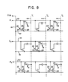
- FIG 8 a schematic diagram is shown of an alternate embodiment of the invention.
- This embodiment is identical to that shown in Figure 5, except that the sources 28 of all of its transistors are connected through its voltage supply lines 32 and the common conductive lead 33 shown in Figures 1 and 3 to a variable preselected voltage supplied by a common voltage supply Vcs.
- Figure 9 shows the voltage waveforms used to drive the circuitry of Figure 8 to produce the pixel pattern shown in Figure 7.
- the output of the common voltage supply V cs' which is connected to the sources of all the transistors 22, is repeatedly alternated between two voltages, a more negative voltage and a more positive voltage.
- the output of U cs is held to a more negative ground voltage during each p-mode and it is held to a more positive voltage of +5 volts during each n-mode.
- the apparatus shown in Figure 8 and the waveforms shown in Figure 9 operate identically to the apparatus shown in Figure 5 and the waveforms shown in Figure 6. It is in the n-mode that the voltage driving scheme shown in Figure 9 differs from that shown in Figure 6. As described above, the voltage driving scheme shown in Figure 6 reverses the voltage polarity across its pixels by simply switching the polarity of the "on" data voltages supplied to its Y lines from a +5 volts during its p-mode to a -5 volts during its n-mode.
- the change in polarity across the pixels 51 is accomplished by both (a.) a change in the common voltage supply V cs from the more negative ground voltage to the more positive voltage of +5 volts and (b.) a reversal of the "on” and “off” data voltages supplied to the Y data lead lines 44, changing the "on” data voltage from +5 volts to ground and changing the "off” data voltage from ground to +5 volts.
- the Y lines 44 discharge, or turn off, pixels in selected rows by supplying their upper electrode with +5 volts, and they charge those pixels to a negative "on" voltage by supplying their upper electrodes with zero volts, which is 5 volts less than the voltage supplied to the bottom pixel electrodes in a selected row.
- the gate voltage supplied on the lines X i , X 2 and X 3 to turn on the transistors of a selected row is +15 volts, which is slightly higher than the +10 volts used for this purpose during the p-mode. This is merely to insure that during the n-mode, when the sources 28 of the transistors in a selected row are supplied with +5 volts, that the voltage supplied to the gate 24 of those transistors is sufficiently higher than that source voltage to keep the selected transistors fully on.
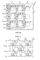
- Figure 10 is a partial top plan view of a bottom substrate subassembly similar to that shown in Figure 1, except that in Figure 10, the voltage supply and control leads located between the pixel rows 14, 15 and 16 are combined into one common conductive lead 72.
- the top X line 72 is labeled X G1 indicating that it is connected to the gates of the first row of pixels.
- the second X line 72 is labeled X S1-G2 , indicating that it is connected to both the sources of the first pixel row and the gates of the second pixel row.
- the third X line 72 shown in those figures is labeled X S2-G3 , indicating that it is connected to both the sources of the second pixel rows and the gates of the third pixel row.
- the bottom most X line 72 is labeled X S3 indicating that it is connected to the sources of the third pixel row.
- the bottom substrate subassembly shown in Figure 10 is combined with a top substrate assembly such as that shown in Figure 2 in a manner similar to that shown in Figures 3 and 4.
- the resultant light influencing display has a circuit diagram similar to that shown in Figure 11, in which each of the bottom pixel electrodes 20 on the bottom substrate subassembly forms a light influencing pixel 51 in conjunction with its associated transparent Y conductive strip 44.
- the display shown in Figure 11 is identical to that shown in Figure 5 except that the control and voltage supply lines between its pixel rows have been combined, as described above.
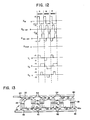
- Figure 12 describes the voltage waveforms which are supplied to the X lines 72 and the Y lines 44 shown in Figure 11 in order to make its 3 x 3 matrix have the pattern shown in Figure 7.
- the voltages supplied to the Y lines shown in Figure 12 are identical to those supplied to the Y lines shown in Figure 6.
- the voltage supplied to the X line X Gl in Figure 12 is identical to that supplied to the X line X 1 in Figure 6. This is because the X line X G1 , being connected only to the gates of transistors in the row below it, functions just like the line X 1 in Figure 6.
- the voltages supplied to the lines X S1-G2 and X S2-G3 are slightly different than those supplied to the lines X 2 and X 3 in Figure 6, because the lines X S1-G2 and X S2-G3 act both to supply gate voltages to the row below them and to supply source voltages to the row above them. These lines are capable of performing both functions because these functions occur at different times.
- the combined source - gate line acts only as a gate voltage supplying line, and the voltages supplied to it are identical to those supplied to the corresponding X lines in Figure 6.
- that line is supplied with an "on" gate voltage of +10 volts to turn on the transistors of the selected row.
- the voltage supplied to that given line is held to a -5 volts to insure that the non-selected transistors in the row directly beneath it remain off.
- a source - gate line supplies a ground source voltage to the transistors in the selected row directly above it, it also supplies a ground gate voltage to the transistors in the non-selected row immediately below it.
- This undesirably high gate voltage for a non-selected row has the effect of enabling transistors in the row immediately beneath the source - gate line to discharge when the bottom pixel electrodes 20 connected to the drains of such transistors are driven to a large negative voltage, such as -10 volts, as described above in the explanation of why a--5 volt gate voltage is normally supplied to the transistors of non-selected rows.
- the voltage supplied to the line X S3 is held at ground. This is because this line functions only to supply voltage to the sources of the transistors in the pixel row immediately above it, and thus it is free to remain at ground at all times.
- FIG. 13 shows a partial top plan view of a row of bottom pixel electrodes 20, with their associate gate voltage and source voltage supplying lines 30 and 32.
- This embodiment of the invention is substantially similar to that shown in Figure 1 except that there are two transistors 22 and 22a associated with each bottom pixel electrode 20.
- the additional transistor 22a is . constructed in the same manner as the transistor 22, shown in Figure 4. The only difference is that the transistor 22a is attached at the opposite end of the bottom electrode 20 than is the transistor 22.
- each bottom pixel electrode 20 The purpose of providing two transistors for each bottom pixel electrode 20 is to provide redundancy. If one of the two transistors does not work, chances are good that the other one will, and thus that the pixel will continue to be able to operate. During fabrication of a display having pixels with two transistors, each of the transistors is tested. If both work, one of them is disconnected by means.of a laser which blows its associated fuse 82, disconnecting it from operation. If both transistors are functional, it is desirable to remove one of them from operation, since each of the transistors allows a small amount of leakage current when turned off, and two transistors have twice as much leakage as one.
- the laser blowable fuses 84 enables the gates 24 of transistors which are not to be used to be removed from operation. This enables the gate capacitance associated with unused transistors to be removed from the lead 30 and, in cases in which a defective transistor has a short between its gate and drain, it enables the shorted gate electrode to be disconnected from operation.
- Figure 13 only shows one row of such dual transistor pixel electrodes, it is to be understood that such a dual transistor arrangement is used in displays having multiple rows, and in displays, similar to that shown in Figure 10, having combined source - gate lines between rows of pixel.
- a light influencing display can be constructed in which each pixel has a separately actualable three terminal device associated with it and yet which does not require crossing address lines on any given substrate.
- the description of the preferred embodiments described above relates to liquid crystal displays, it is to be understood that the invention is applicable to other types of light influencing displays as well, such as electroluminiscent and electrochromic displays.
- data voltages are supplied to all the pixels of a selected row in parallel.
- the present invention also applies to light influencing displays in which a data voltage is supplied to only one pixel in a selected row at a time, while the data leads connected to the other pixels in the selected row are allowed to have their voltages float.
- the present invention is applicable to displays in which the pixels can show gray values as well as the on and off values described above.
- Such gray values can be achieved by selecting the preselected voltage and the data voltage supplied to the electrodes of a given pixel so that the voltage applied across that pixel is sufficient to only partially change the optical properties of its light influencing material.
- those skilled in the art may make various other modifications or additions to the preferred embodiments chosen to illustrate the invention without departing from the spirit and scope of the present contribution to the art.
Landscapes
- Physics & Mathematics (AREA)
- Engineering & Computer Science (AREA)
- Nonlinear Science (AREA)
- Crystallography & Structural Chemistry (AREA)
- General Physics & Mathematics (AREA)
- Chemical & Material Sciences (AREA)
- Computer Hardware Design (AREA)
- Theoretical Computer Science (AREA)
- Microelectronics & Electronic Packaging (AREA)
- Mathematical Physics (AREA)
- Optics & Photonics (AREA)
- Liquid Crystal (AREA)
- Devices For Indicating Variable Information By Combining Individual Elements (AREA)
- Control Of Indicators Other Than Cathode Ray Tubes (AREA)
Abstract
Description
- The present invention relates generally to light influencing displays and more particularly to active matrix displays in which each display element is controlled by a separate three terminal control device, such as a transistor, and to methods of using the same.
- Light influencing displays are well known in the prior art. They include liquid crystal, electroluminescent, and electrochromic displays.
- It is common in such displays for there to be a plurality of individually addressable picture elements, called pixels, each having a separate pair of opposing pixel electrodes, with light influencing material between them. Voltages are selectively applied to the electrode pairs, causing the light influencing material between them to emit light or change optical density. Commonly these opposing pixel electrodes are located on opposing substrates, such as opposing glass plates, with the light influencing material, such as liquid crystal material, located between the substrates.
- In relatively small arrays of pixels, such as those found in many digital watches it is common to have all the pixel electrodes on one substrate connected in common and to have a separate address line for selectively applying voltages to each of the pixel electrodes on the second substrate, thus enabling each pixel to be individually selected . However, in large arrays, such as large x - y arrays, it proves impractical to have a separate address line connected to each pixel because too much room would be required by so many lines. Thus, in displays with many pixels it is common to use x - y matrix addressing, in which all the bottom pixel electrodes of a given row are connected to an address line associated with that row and all the top pixel electrodes of a given column are connected to an address line associated with that column. This enables each pixel to be addressed by selecting its associated x and y address lines.
- In relatively small x - y arrays each of the x and y lines is usually directly connected, without. intervening electronic devices, to the bottom or top pixel electrodes in its associated row or column. Usually the pixels of such an array are driven sequentially in a scanning process in which each row is selected successively, and, during the selection of each row, each column is selected successively, causing the pixels of each row to be scanned in sequential order. During the time allotted for the selection of each pixel the circuitry decides whether that pixel is to be turned on or off by controlling the amplitude of the voltage applied across the pixel. In parallel scanned arrays each of the rows is selected in succession, and during the selection of each row all of the column lines are driven in parallel with individually selected voltages, turning each pixel in the row to a desired state, either "on" or "off". Such multiplexing scanning schemes in which the pixels are driven directly by their x and y address lines without intervening electronic devices work well for relatively small arrays. But as array size grows, the amount of time for the application of a voltage to a given pixel, or row of pixels, decreases. As a result, the percentage of time during each scanning cycle that a given pixel has a voltage applied across it decreases, thereby decreasing the average contrast between its "on" state and its "off" state. For this reason large multiplexed displays tend to produce images with poor contrast, making such displays difficult to read.
- One way of overcoming this limitation is to use active display matrixes instead of multiplexed displays. In active display matrixes each of the pixels has associated with it a non-linear electronic device which acts as a switch. This switch enables current to flow to or from the pixel during the brief period when the pixel is selected, enabling it to rapidly change state from "off" to "on", or vice versa, but it tends to prevent current flow to or from the pixel when.it is not selected, so the charge placed on the pixel during its brief selection period is substantially maintained during the rest of the scanning cycle . As a result, the pixel tends to maintain its "on" or its "off" state during the entire scanning cycle, greatly increasing the contrast and readability of the display.
- One type of electronic device commonly used with the pixels of active display matrixes is the three terminal control device, such as the transistor. A three terminal control device is one that has two current path electrodes and a control electrode, with the effective resistance between the two current path electrodes being controlled as a function of a signal supplied to the control electrode. For example, in the thin film field effect transistors often used in active matrix displays, the voltage applied to the gate electrode controls the amount of current which flows between the source and the drain of the transistor.
- The three terminal devices are usually arranged on one substrate of the display, with one of their current path electrodes connected to an electrode of their associated pixel. In the prior art, crossing x and y lines are also placed on the substrate to enable each three terminal device and its associated pixel to be individually addressed. One of the sets of the address lines, for example, the x lines, are connected to the control electrodes of the three terminal devices, with each x line being connected to each of the control electrodes in its associated row of pixels. Correspondingly, the other set of address lines, the y lines, are connected to one of the current path electrodes of the control devices; with each y line being connected to a current path electrode associated with each pixel in its column. All the pixel electrodes on the display's other substrate are usually connected to a common voltage, such as ground. A given pixel is selected by applying a proper voltage between the x line connected to the control electrode of its three terminal device and the y line connected to the current path electrode of its three terminal device. For example, when the three terminal devices are thin film field effect transistors, the source of each transistor is connected to a y line and the gate of each transistor is connected to an x line. In such a structure, a selected transistor is turned on or off by providing the desired voltages between the x line connected to its gate and the y line connected to its source.
- Roughly speaking the present invention relates to a light influencing display having a plurality of pixels, each with a first electrode connected to a preselected voltage through a switchable deposited semiconductor control device and each with an opposing second electrode. The invention provides means for turning on each control device of a first selected group of the pixels, so the first electrode of each pixel in that group is connected to a preselected voltage. It also provides means for supplying a data voltage to each second electrode in a second selected group of the pixels. As a result, a pixel which belongs to both groups is addressed by having a selected voltage applied between its first and second electrodes.
- More particularly, the present invention relates to a light influencing display which has a plurality of pixels, each including a first electrode formed on a first surface and an opposing, second electrode formed on a second surface. The plurality of pixels is divided into pixel groups, each consisting of a separate plurality of pixels. A separate three terminal control device is formed of deposited semiconductor material on the first surface in association with each pixel. Each of the control devices has two current path terminals and a control terminal which controls the conductivity between them. A first of each control devices' current path terminals is connected to the first electrode of its associated pixel. The display further includes a separate voltage supply lead formed on the first surface in association with each pixel group, with each such voltage supply lead being connected to the second current path terminal associated with its pixel group. A conductive control lead is also formed on the first surface in association with each pixel group, with each such control lead being connected to the control terminals associated with its pixel group. A plurality of conductive data leads is formed on the second surface, with a different data lead being electrically connected to each second electrode of a given pixel group, and with individual data leads being connected to at least one second pixel electrode in each of a plurality of pixel groups. As a result of this structure, a desired voltage. can be applied between the electrodes of a given pixel by using a selected control lead to turn on the control device of that pixel's pixel group, and by using the data lead connected to the pixel to supply a selected data voltage to its second electrode.
- In a preferred embodiment of the invention the first and second insulative surfaces are the surfaces of two opposing substrates formed of a material such as glass, and a light influencing display material, such as liquid crystal material, is placed between the first and second electrodes of each pixel. Preferably, the control devices associated with each pixel are transistors, such as thin film field effect transistors having channel regions formed of a deposited semiconductor material, such as an amorphous alloy of silicon, including hydrogen and/or fluorine as density of state reducing elements.
- In some embodiments of the-invention, each first pixel electrode has two separate three terminal control devices formed in association with it to provide redundancy, and at least one of the control devices has a laser blowable fuse connected to one or two of its electrodes so as to enable that controT device to be removed from effective operation. Also in some embodiments of the invention, the voltage supply lead associated with one pixel group functions as a control lead associated with another pixel group.
- In preferred embodiments of the invention, the pixels in each pixel group are arranged in a row and the voltage supply and control leads associated with each pixel row form two non-crossing parallel conductive lines extending in the direction of that row. In fact, it is preferred that the pixels are arranged in an x - y array so that each pixel belongs to both a pixel row and a pixel column. Preferably, the data lead is connected to the second pixel electrode of all the pixels in a given pixel column, so that by selectively supplying the proper voltage through a control lead associated with a selected pixel row and by supplying a voltage through a data lead connected to a selected pixel column, the pixel at the intersection of the selected row and column has a voltage applied across it.
- In one alternate embodiment of the invention, each pixel row has associated with it one voltage supply lead and one control lead in addition to the voltage supply and control leads of any other pixel row, so that each additional row requires two additional conductive leads. In a different alternate embodiment of the invention, the voltage supply lead associated with one pixel row also functions as the control lead associated with an adjacent pixel row, so that each additional row only requires one additional conductive lead.
- The present invention also relates to subassemblies for use in light influencing displays of the type described above. Such subassemblies comprise the elements formed on the first insulative surface in the embodiments of the invention described above.
- The present invention also relates to the method of supplying a voltage to a selected pixel from among a plurality of pixels divided into groups. The method is applicable in cases in which each pixel has a first and a second electrode and has a separate three terminal control device of the type described above, with a first of the control device's current path terminals connected to the pixel's first electrode. The method of the present invention comprises supplying preselected voltages to the second current path terminals of the control devices associated with each pixel. The method further includes supplying a data voltage through a selected data lead to a second pixel electrode in each of the pixel groups, including the second pixel electrode of the pixel to be selected. It also includes supplying an "on" signal to each of the control terminals of the control devices associated with the pixel group including the selected pixel, so as to turn on the conductivity between the current path terminals of its control devices, thus effectively connecting the first electrode of the selected pixel to a given preselected voltage. The method also includes supplying an "off" signal to each of the control terminals of the control devices associated with other, non-selected, pixel groups, so as to turn off the conductivity between the current path terminals of their control devices. As a result, a selected voltage is applied across the selected pixel, but not across pixels in the non-selected pixel groups.
- In a preferred embodiment of this method, a plurality of separately selectable data voltages are supplied in parallel through a plurality of data leads, with each selected voltage being supplied to one second pixel electrode in each pixel group. As a result, a plurality of pixels in the selected pixel group have a separately selected voltage applied between their first and second pixel electrodes at the same time.
- According to a preferred embodiment of the method of the present invention, the pixels are arranged in an x - y array in which each pixel group forms a row in the array, and each pixel, besides being in a pixel row, is also in a pixel column. According to this method, the supplying of a voltage through a selected data lead includes supplying such a voltage through a data lead to each second electrode of each pixel belonging to a given pixel column.
- According to another embodiment of the method of the present invention, a separate voltage supply lead is used to supply the preselected voltages to the second current path terminals associated with each pixel group. A separate control lead is used to supply the "on" and "off" signals to the control terminals associated with each pixel group. In one such embodiment, the same conductive lead which is used as the control lead to supply the "on" and "off" signals to the control terminals associated with 0πe pixel group is also used at other times as the voltage supply lead to supply a certain preselected voltage to the second current path terminals associated with another pixel group when that other pixel group is the selected pixel group.
- The method of the present invention has two alternate embodiments for use with liquid crystal displays for periodically reversing the polarity of the voltages supplied across the pixels of such displays, so as to reduce the deterioration of such pixels which would result from a prolonged net direct current flow across them. In the first alternate method the preselected voltage supplied to the second current path terminals associated with the selected pixel group is held constant and the polarity of the data voltages applied to the second pixel electrodes is periodically reversed. In the second alternate method, the preselected voltage supplied to the second current path terminals associated with the selected pixel groups is periodically changed between a more positive voltage and a more negative voltage. In this embodiment the data voltages supplied to the second pixel electrodes are substantially limited to voltages below the preselected voltage when the preselected voltage is at the more positive level, and are substantially limited to voltages above the preselected voltage when the preselected voltage is at the more negative level.
- In one preferred embodiment of the present invention, the preselected voltages are supplied to the second current path terminals of all the pixel groups in common.
- In a preferred embodiment of the invention, the control devices are thin film field effect transistors and the current path terminals are sources and drains of such transistors, and the control terminals are the gates of such transistors. In such an embodiment, the "on" signal supplied to the gate electrodes of the selected pixel group is a voltage sufficiently higher than the preselected voltage supplied to the source electrodes of the selected group so as to turn the transistors of the selected group "on". In such an embodiment, the "off" signal supplied to the gate electrodes associated with the non-selected pixel groups is sufficiently low to keep the transistors of those non-selected pixel groups "off". Preferably, this "off" signal is a voltage which is sufficiently low to keep the transistors of the non-selected pixel groups "off", even when the voltage on the first pixel electrode connected to the first current path terminals of those transistors is less than the preselected voltage supplied to the source electrodes of such transistors by twice the largest data voltage applied across the pixels.
- Accordingly, a first object of the invention is to provide a light influencing display including first and second surfaces, a plurality of pixels arranged in rows and columns, each including a first electrode formed on the first surface, an opposing second electrode formed on the second surface and light influencing material between the first and second electrodes, characterized by: a separate three terminal control device, formed of semiconductor material on the first surface, associated with each of the pixels, with each of the control devices having two current path terminals and a control terminal which controls the conductivity between those two current path terminals, and with a first of the current path terminals of each control device being connected to the first pixel electrode of its associated pixel. The display further includes a separate conductive voltage supply lead formed on the first surface in association with each row of pixels, the voltage supply lead extending in the direction of its associated row and being connected to the second current path terminals of the control devices associated with its row, a separate conductive control lead formed on the first surface in association with each row of pixels, the control lead extending in the direction of its associated row and being connected to the control terminals of the control devices in that row, and a separate conductive data lead formed on the second surface in association with each column of pixels, the data lead extending in the direction of its associated column and being connected to the second pixel electrodes in that column.
- A second object of the invention is to provide a subassembly for use in a light influencing display including a first insulative surface, characterized by: a plurality of first pixel electrodes formed on the first surface, with the pixel electrodes being divided into a plurality of pixel electrode groups, each consisting of a separate plurality of pixel electrodes, and a corresponding plurality of three terminal control devices formed of deposited semiconductor material on the first surface, with one such control device being formed in association with each of the pixel electrodes, with each control device having two current path terminals and a control terminal which controls the conductivity between those two current path terminals, and with a first of the current path terminals of each control device being connected to its associated first pixel electrode. A separate conductive voltage supply lead is formed on the first surface in association with each of the pixel electrode groups, with each of the voltage supply leads being connected.to the second current path terminals of the control devices associated with its electrode group, and a separate conductive control lead is formed on the first surface in association with each of the pixel electrode groups, with each of the control leads being connected to the control terminals of the control devices associated with its electrode group.
- A third object of the invention is to provide a method of supplying a voltage to a selected pixel from among a plurality of pixels divided into separate pixel groups, in which each pixel has a first and a second electrode, and in which each pixel has a separate three terminal control device associated with it, each having two current path terminals and a control terminal which controls the conductivity between them, with a first of the current path terminals of each control device being connected to the first electrode of its associated pixel, the method characterized by: supplying preselected voltages to the second current path terminals of the control devices associated with each pixel, and supplying a data voltage through a selected data lead to one second electrode in each pixel group, including the second electrode of the selected pixel. The method further includes supplying an "on" signal to each of the control terminals of the control devices associated with the pixel group which includes the selected pixel, so as to select that pixel group by turning on the conductivity between the current path terminals of its control devices, effectively connecting the first electrode of the selected pixel to a given preselected voltage, and supplying an "off" signal to each of the control terminals of the control devices associated with other, non-selected pixel groups, so as to turn off the conductivity between the current path terminals of their control devices effectively isolating their first electrodes from the preselected voltages.
- In the drawings, which form an integral part of the specification of the present application and which are to be read in conjunction therewith, and in which like reference numerals are employed to designate similar components in various views:
- Figure 1 is a representational partial top plan view of a single substrate subassembly for a light influencing display according to one embodiment of the present invention; .
- Figure 2 is a representational partial top plan view of a second substrate for use in conjunction with the first substrate shown in Figure 1 for constructing a light influencing display according to one embodiment of the invention;
- Figure 3 is a representational partial top plan view of a light influencing display formed by placing the substrate shown in Figure 2 on top of the substrate shown in Figure 1, with the combination column address and pixel electrode lines Yl, Y2 and Y3 of the second substrate shown in dotted lines;
- Figure 4 is a partial cross-sectional side view of the light influencing display shown in Figure 3, taken along the lines 4 - 4 shown in Figure 3;
- Figure 5 is an electrical schematic diagram of the electrical circuitry formed by the embodiment of the invention shown in Figure 3;
- Figure 6 is a set of wave diagrams showing the voltages supplied to the X and Y lines of the embodiment of the invention shown in Figures 3 and 5;
- Figure 7 is a schematic representation of the distribution of "on" and "off" pixels which result when the embodiment of the invention shown in Figures 3 and 5 is supplied with the wave forms shown in Figure 6;
- Figure 8 is a schematic circuit diagram identical to that shown in Figure 5 except that all the sources of its transistors, instead of being tied to ground as in Figure 5, are tied to a common variable voltage source Vcs;
- Figure 9 is a set of wave diagrams showing the voltages supplied by the voltage supply V and to the x and y lines in Figure 8 to produce the pixel pattern shown in Figure 7;
- Figure 10 is a representational partial top plan view of a single substrate subassembly for use in a light influencing display according to one embodiment of the present invention, which is similar to that shown in Figure 1 except that the gate and source lines connected between adjacent rows of pixels are combined;
- Figure 11 is a schematic circuit diagram of the light influencing display produced when a top substrate, such as that shown in Figure 2 is combined with the bottom substrate shown in Figure 10;
- Figure 12 is a set of wave diagrams showing the signals supplied to the x lines and y lines of the circuit shown in Figure 11 in order to produce the pixel pattern shown in Figure 7; and
- Figure 13 is a partial top plan view showing the layout of a single row of pixel electrodes and their associated transistors and gate and source voltage supply lines according to an alternate embodiment of the invention in which each pixel has associated with it two thin film field effect transistors, each of which has laser blowable fuse links which can be blown to remove its associated transistor from operation.
- Referring now to Figure 1, a portion of a single substrate subassembly for use in a light influencing display embodying the present invention is shown. The
subassembly 10 includessubstrate 12 which has an insulative surface and a plurality ofpixel rows rows first pixel electrodes 20 formed on the substrate surface. These first pixel electrodes are arranged in an x - y matrix with theelectrodes 20 being aligned inpixel columns pixel rows - Each of the
first pixel electrodes 20 has associated with it a separate threeterminal control device 22, each of which has acontrol terminal 24 and two current path terminals.. The two current path terminals include a firstcurrent path terminal 26 and a secondcurrent path terminal 28. In the preferred embodiment shown, the threeterminal control devices 22 are thin film field effect transistors, with thecontrol terminals 24 being gate electrodes, the firstcurrent path terminals 26 being drain electrodes and the secondcurrent path terminals 28 being source electrodes. In this specification, for purposes of simplicity, theelectrodes 26 are always called the drains, and theelectrodes 28 are always called the sources, of thetransistors 22, regardless of the direction of current flow through the transistors. The structure of thetransistors 22 is shown in a simplified representational form in Figure 1, but is shown in considerably more detail in Figure 4 explained below. - The
subassembly 10 includes aconductive control lead 30 formed on the surface ofsubstrate 12 and connected to the control terminal of each of the control devices associated with eachpixel row rows subassembly 10 further includes a separate conductivevoltage supply lead 32 associated with each pixel row. The voltage supply leads 32 are electrically separate from the control leads 30. Each of the voltage supply leads are formed on the surface ofsubstrate 12 and are connected to the secondcurrent.path terminal 28 of each of the control devices of its associated pixel row. Theleads 30 and.32 associated with each pixel row extend parallel to each other in the direction of that row. Even though the voltage supply leads 32 are electrically connected to a commonconductive lead 33, they are considered separate for purposes of circuit layout because each of them extends along a different row. - Referring now to Figure 2, a
second substrate assembly 40 is shown. This second assembly is designed for use in conjunction with thesubassembly 10 shown in Figure 1 to form a light influencing display as shown in Figures 3 and 4. Thesecond substrate assembly 40 comprises asubstrate 42 having an insulative surface upon which electrically separate columns of pixel electrodes are formed. - When a display to be formed according to the present invention is to be back-lighted, both
substrates substrates substrate assembly 40 includes a plurality of transparentconductive strips 44 formed on its lower surface. Such transparent conductive strips can be formed by photolithographic means of a transparent conductive oxide such as indium tin oxide. In such a back lighted embodiment thepixel electrodes 20, formed on thefirst substrate 10, are also formed by photolithographic means out of a transparent conductive oxide such as indium tin oxide, and the conductive leads 30, 32 and 33, and the transistor gate, source and drain electrodes of that substrate are formed by photolithographic means out of conductive metal. - Referring now to Figures 3 and 4, a
light influencing display 50 according to one embodiment of the present invention is assembled by placing thesecond substrate assembly 40 over thefirst substrate assembly 10 so that the conductive strips 44 (which are shown in dotted lines in Figure 3) overlie thepixel electrodes 20. Theupper substrate assembly 40 is positioned so that the conductive strips Y1, Y2 and Y3 overlie thebottom pixel electrodes 20 associated with thepixel columns bottom pixel electrode 20 is spaced from, and is substantially parallel to, thatbottom electrode 20, and forms an upper, or second, electrode surface in opposition to that given bottom electrode. Theconductive strips 44 not only act as second pixel electrodes, but they also each act as conductive data leads for supplying voltages to the pixel electrode surfaces they include. - Referring now to Figure 4, before the assembly of the
light influencing display 50 is complete, a thin layer oflight influencing material 52 is placed between its twosubstrates bottom electrode 20 on thesubstrate 12 and its opposing top electrode formed by theconductive strip 44 on theupper substrate 42, that voltage changes the optical properties of thelight influencing material 52 located between those two electrodes. This combination of abottom pixel electrode 20, the portion of theconductive strip 44 which opposes it, and the light influencing material in between forms apixel 51. In the embodiment shown, thelight influencing material 52 is a liquid crystal material. The application of a voltage between the electrodes of a given pixel changes the orientation of the liquid crystal molecules between those electrodes, changing the effect of the liquid crystal material upon light passing through it. As is well known in the art of flat panel displays, many types of liquid crystal displays require polarizing and alignment layers in association with their pixels. Such polarizing and alignment layers have not been shown in Figure 4 for purposes of simplification since the nature of such layers is well known in the art of liquid crystal displays. - Figure 4 shows a cross sectional view of a thin film
field effect transistor 22 formed upon thesubstrate 12. Thin film field effect transistors can be formed in a variety of methods which are known in the art of thin film transistors. The embodiment of the invention shown in Figure 4 includes atransistor 22, in which agate electrode 24 is formed upon theinsulative substrate 12 by photolithographic means. Also formed in the same photolithographic step is thex line 30 to which each gate electrode is connected. The gate electrode and its connected x line are formed from an opaque metal, such as chromium, which is preferably .1 micron to .3 microns thick. After the metal layer containing thegate electrodes 24 and the xlines 30 has been deposited and patterned, agate insulating layer 54 is deposited over thesubstrate 12. Thegate insulator 54 has a thickness preferably from about .1 micron to about .3 microns and is formed, for example, from a material such as silicon oxide (SiOx), silicon nitride (SixNy), or silicon oxy-nitride (SiOXNy). - After the
gate insulating layer 54 has been formed, a layer of indium tin oxide is deposited over thesubstrate 12 and is patterned to form abottom pixel electrode 20 next to the site of eachtransistor 22. - Next a layer of semiconductor material is deposited. This layer is patterned by photolithographic techniques to cover the
gate electrode 24 as well as an area on each side of that gate over which the source and drain electrodes will subsequently be deposited. Preferably this deposited semiconductor material is formed of a relatively intrinsic amorphous silicon alloy containing hydrogen and/or fluorine as density of states reducing elements. By the term "amorphous" is meant an alloy or material which has long-range disorder, although it may have short or intermediate order or even contain at times some crystalline inclusions. Such materials can include, for example, microcrystalline or polycrystalline semiconductor material. - The
layer 56 of semiconductor material can be formed by the plasma assisted chemical vapor deposition of silane plus hydrogen, silicon tetrafluoride and silane, or of silicon tetrafluoride and hydrogen, as disclosed, for example, is U. S. Patent No. 4,226,898 which issued on October 7, 1980 in the names of Stanford R. Ovshinsky and Arun Madan for "Amorphous Semiconductors Equivalent To Crystalline Semiconductors Produced By A Glow Discharge Process" which patent is incorporated herein by reference. The semiconductor layer can have a thickness from about .05 to about 1 micron, and preferably from about .1 to about .3 microns. - In alternate embodiments of the invention, the deposited semiconductor material includes other materials, such as germanium or cadmium selenide.
- The top 300 to 500 angstroms of
layer 56 is formed of an N+ dopedsublayer 57. Thissurface sublayer 57 can be formed by introducing phosphine gas into the deposition chamber during the end of the deposition oflayer 56. Such a gas introduces phosphorus doping atoms into the top portion oflayer 56. ThisN+ sublayer 57 causes the semiconductor material oflayer 56 to form a much better ohmic contact with the metal of the source and drain contacts which are formed on top of it. - After the
layer 56 has been deposited and patterned, a layer of metal, preferably between .1 and .3 microns thick, is deposited oversubstrate 12. The metal of this layer is chosen to form a good ohmic contact with the N+ material ofsublayer 57. For example, metals such as molybdenum, aluminum, chromium or molybdenum tantallium alloy all form good ohmic contacts with the N+ material ofsublayer 57. - The metal layer is then patterned by photolithographic means to form separate source and drain
electrode transistor 22. Also formed during this patterning step are the metal voltage supply leads 32 which are connected to thesources 28. Thedrain 26 is patterned to overlie a small portion of thebottom pixel electrode 20 so as to make electrical contact with that electrode, and thesource 28 and drain 26 are both patterned so that there is a gap between them directly over thegate 24. After the source and drain have been patterned, they are used as masks in an etching process which etches away thetop N+ sublayer 57 located in the gap between them. This is done to prevent the relatively high conductivity of the N+ sublayer from short circuiting the fieldeffect transistor channel 58 formed inlayer 56 between the source and drain. - After the
source 28 and drain 26 have been formed and the portion of the N+ sublayer between them has been etched away, an electricallyinsulative passivation layer 60, formed of material, such as silicon nitride, silicon dioxide, or polyimide, is coated over the entire bottom substrate. Thelayer 60 protects the electrodes oftransistor 22 and thebottom pixel electrodes 20 from electrolysis with the liquid crystal material of the display in which they are used. In addition, since it provides an insulator between thebottom pixel electrode 20 and the top electrode surfaces formed by thestrip conductors 44, thelayer 60 substantially reduces electrolytic current flow between those top and bottom electrode surfaces; thus greatly reducing the deterioration of the electrode surfaces on the top substrate as well as those on the bottom substrate. It should also be noted that in displays in which alignment layers (not shown in the Figures) are placed over the top and bottom electrode surfaces, such alignment layers also provide the electrode surfaces with protection from electrolysis. - A
light blocking layer 62 formed of metal approximately .1 micron thick is deposited over the substrate and is patterned to cover, and prevent light from hitting, thesemiconductor material 56. This light blocking layer is used because amorphous alloys of silicon are photoconductive and thus thetransistor 22 would have its operating characteristics altered unless ambient light was blocked from hitting its semiconductor material by such a light blocking layer. The capacitance between the electrodes oftransistor 22 and the metallight blocking layer 62 can be decreased by increasing the thickness of thepassivation layer 60 or by reducing the overlap between thelight blocking layer 62 and thesource 28 anddrain 26. This capacitance problem can be avoided all together by forming theinsulative passivation layer 60 of a light blocking material. In some embodiments of the invention however, it might actually be desired to have some capacitance between the source and drain electrodes of thetransistors 22. Such capacitance might be desired to partially compensate for the capacitance between the gate and the drain of such transistors. In such embodiments the metal of thelight blocking layer 62 can be used to capacitively couple the source and drain by having that layer patterned to overlap each of those two electrodes. - The
transistor 22 operates in the normal manner of an N channel enhancement mode thin film TFT. That is, when a voltage which is sufficiently positive relative to the lowest voltage placed on either its source or its drain electrode is applied to its gate electrode, a conductive channel is formed in the portion of thesemiconductor layer 56 between its source and drain, greatly increasing the conductivity between those electrodes. In the absence of such a positive gate voltage, the low conductivity of the relatively intrinsic amorphous silicon alloy oflayer 56 makes the circuit path between the source and drain have a very high resistance, substantially electrically isolating those two electrodes. - Referring now to Figure 5, a schematic diagram of the 3 x 3 pixel array of Figure 3 is shown. The circuit elements formed on the
bottom substrate 12 are shown in solid lines in Figure 5 and the circuit elements formed by thestrip conductors 44 on theupper substrate 42 are shown in dotted lines. Each of thepixels 51 formed by abottom electrode 20 and a portion of thestrip conductor 44 has associated with it a capacitance, as indicated in Figure 5. The sources of all of thetransistors 22 are connected to ground through the second conductive leads 32. - Figure 6 showns the voltage waveforms applied to the circuit shown in Figure 5 to cause its pixels to form the pattern shown in Figure 7. In the embodiment shown, the
pixels 51 are light transmissive unless a voltage is applied across them, in which case they become light blocking or dark. The waveforms xl, X2, and X3 are voltage waveforms which are supplied through the control leads 30 to thegates 24 of the transistors in therow strip conductors 44, which function as data leads, to thepixels 51 in thecolumns drains 26 of their associatedtransistors 22. -The source electrodes of all thetransistors 22 are connected through the voltage supply leads 32 to ground. - In operation, each of the
transistors 22 in a givenrow respective X line 30 is supplied with a positive "on" gate voltage, which for the TFTs of the preferred embodiment is approximately 10 volts. Once thetransistors 22 of a given row are turned on, the conductivity between thesources 28 and drains 26 of that row is greatly increased, effectively connecting thebottom pixel electrodes 20 of that row to ground. When a given row is selected in such a manner, a plurality of selected data voltages are applied in parallel to the second pixel electrodes of the row by means of the data leads, or Y lines, formed by the conductive strips 44. This causes each of thepixels 51 in the selected row to be charged to a voltage equal to the difference between the data voltage on its associated Y line and the ground voltage on itssource line 32. For example, during the first third of each p-mode, when the address line X, is high, the Y address line Y is supplied with an "on" data voltage of approximately +5 volts, and the Y address lines Y2 and Y3 are supplied with "off" data voltages of zero volts. As a result, the left pixel of the top row is turned on, whereas the remaining two pixels of that row remain off. In the embodiments of the invention described in Figure 7 and the rest of this specification, the pixels which are turned on are made opaque or dark, and the pixels which are left off remain transparent or light. It is to be understood, however, that the present invention is also applicable to displays which behave just the opposite, that is, in which pixels that have a voltage applied across them turn transparent and those without a voltage applied across them remain opaque. - During the period when the first row is selected and has its transistors turned on, the address lines X2 and X3, which are connected to the other non-selected pixel rows, are supplied with a negative potential of -5 volts. This negative potential extends below ground by -5 volts and insures that each of the transistors in non-selected rows remain off. In fact this voltage is sufficiently low to insure that the transistors in the non-selected rows remain off, even when the voltage on their associated
bottom pixels 20, which are connected to theirdrains 26, is less than ground by twice the "on" pixel voltage of 5 volts. This is necessary for the following reason. If a given pixel is charged to +5 volts when its row is selected by placing itsbottom pixel electrode 20 at ground and its Y line at +5 volts, this charge causes its bottom pixel electrode to remain 5 volts below the voltage on its Y line for as long as that 5 volt charge remains on the pixel. Since the leakage of charge across the pixel through the liquid crystal material, is relatively small during the period between the pixel's recharging, and since the transistor associated with the pixel is supposed to be turned off when its row is non-selected, a substantial portion of the +5 volt charge remains on the pixel during the period when it is non-selected. Thus, if the Y line drops to zero volts during the selection of another row, the voltage on the pixel'sbottom electrode 20 drop to approximately -5 volts. Even more extreme, if during the n-mode, described below, the Y line drops to a minus "on" pixel voltage of -5 volts, its bottom pixel electrode will drop to approximately -10 volts. Because this large negative voltage is connected to their drain, the transistors in non-selected rows should be supplied with a negative gate voltage to insure that they remain off. Since the gate threshold voltage of the transistors of the.preferred embodiment is more than 5 volts, the "off" gate voltage of -5 volts is sufficient to keep the non-selected transistors off even when the voltage on their drains, reaches -10 volts. - In the second third of each p-mode period, the second X line, X2 is supplied with a positive, or "on", gate voltage and all the other X lines are supplied with an "off" gate voltage of -5 volts. As ' shown in Figure 6, during this period the line Y1 is held at zero volts and the lines Y2 and Y3 are supplied with "on" voltages of +5 volts. Thus, as is shown in Figure 7, the first pixel in the row X2 remains off, and thus transparent, whereas the second and third pixels in that row are turned on, and thus are light blocking. Similarly, during the last third of the p-modes the last row X3 has a positive "on" gate voltage supplied to its transistors, and the other rows have negative or "off" gate voltages supplied to their transistors. During this time, the line Y1 is supplied with a zero "off" voltage, the line Y2 is supplied with a positive "on" voltage and line Y3 is supplied with a zero "off" voltage. Thus, the first and third transistors of that row remain off, and only the middle transistor of that row is turned on.
- As is well known in the art of liquid crystal displays, it is important to periodically reverse the polarity of the voltages applied across individual pixels. This is because a prolonged net dc current flow damages such pixels. For this reason the voltage driving scheme used to power the display shown schematically in Figure 5 is divided into alternating positive and negative modes, indicated by the labels p-mode and n-mode in Figure 6. In this driving scheme the voltages applied through the X lines, X1, X2 and X3 to the gates of the
transistors 22 are the same during both the p and n modes. However, the polarity of the voltages applied to the Y lines, Y1, Y2 and Y3 during the n-mode are reversed in polarity relative to those applied during the p-mode. Thus the voltages supplied to the X lines turn on the transistors of the display in the same manner during both the p-and n-modes, but during the n-mode thepixels 51 which are to be turned on are supplied with a negative "on" voltage of -5 volts, rather than a positive "on" voltage of +5 volts. - In a typical embodiment of the invention, the device alternates between the p-and n-modes at 60 times a second, the rate used to alternate between fields of a standard video signal. As a result, a pixel which is turned on has the polarity of the voltage applied across it rapidly varied, preventing any net dc current flow through the liquid crystal material associated with that pixel. Furthermore, since the entire pixel array has each of its pixels rewritten 60 times a second, there is no perceived flicker on the display.
- Referring now to Figure 8, a schematic diagram is shown of an alternate embodiment of the invention. This embodiment is identical to that shown in Figure 5, except that the
sources 28 of all of its transistors are connected through itsvoltage supply lines 32 and the commonconductive lead 33 shown in Figures 1 and 3 to a variable preselected voltage supplied by a common voltage supply Vcs. Figure 9 shows the voltage waveforms used to drive the circuitry of Figure 8 to produce the pixel pattern shown in Figure 7. As is shown in Figure 9, the output of the common voltage supply Vcs' which is connected to the sources of all thetransistors 22, is repeatedly alternated between two voltages, a more negative voltage and a more positive voltage. The output of Ucs is held to a more negative ground voltage during each p-mode and it is held to a more positive voltage of +5 volts during each n-mode. - During the p-mode the apparatus shown in Figure 8 and the waveforms shown in Figure 9 operate identically to the apparatus shown in Figure 5 and the waveforms shown in Figure 6. It is in the n-mode that the voltage driving scheme shown in Figure 9 differs from that shown in Figure 6. As described above, the voltage driving scheme shown in Figure 6 reverses the voltage polarity across its pixels by simply switching the polarity of the "on" data voltages supplied to its Y lines from a +5 volts during its p-mode to a -5 volts during its n-mode. In the voltage driving scheme shown in Figure 9, on the other hand, the change in polarity across the
pixels 51 is accomplished by both (a.) a change in the common voltage supply Vcs from the more negative ground voltage to the more positive voltage of +5 volts and (b.) a reversal of the "on" and "off" data voltages supplied to the Y data leadlines 44, changing the "on" data voltage from +5 volts to ground and changing the "off" data voltage from ground to +5 volts. During the n-mode, when the sources of all of thetransistors 22 are supplied with the more positive voltage of +5 volts, the Y lines 44 discharge, or turn off, pixels in selected rows by supplying their upper electrode with +5 volts, and they charge those pixels to a negative "on" voltage by supplying their upper electrodes with zero volts, which is 5 volts less than the voltage supplied to the bottom pixel electrodes in a selected row. - During the n-mode, the gate voltage supplied on the lines Xi, X2 and X3 to turn on the transistors of a selected row is +15 volts, which is slightly higher than the +10 volts used for this purpose during the p-mode. This is merely to insure that during the n-mode, when the
sources 28 of the transistors in a selected row are supplied with +5 volts, that the voltage supplied to thegate 24 of those transistors is sufficiently higher than that source voltage to keep the selected transistors fully on. - Referring now to'Figures 10 and 11 an alternate embodiment of the invention is shown. Figure 10 is a partial top plan view of a bottom substrate subassembly similar to that shown in Figure 1, except that in Figure 10, the voltage supply and control leads located between the
pixel rows conductive lead 72. This greatly simplifies the wiring associated with an x - y pixel array, reducing almost in half the number of address lines required on the bottom substrate subassembly in large x - y arrays. As is shown in Figures 10 and 11, thetop X line 72 is labeled XG1 indicating that it is connected to the gates of the first row of pixels. Thesecond X line 72 is labeled XS1-G2, indicating that it is connected to both the sources of the first pixel row and the gates of the second pixel row. Similarly, thethird X line 72 shown in those figures is labeled XS2-G3, indicating that it is connected to both the sources of the second pixel rows and the gates of the third pixel row. Finally, the bottommost X line 72 is labeled XS3 indicating that it is connected to the sources of the third pixel row. - The bottom substrate subassembly shown in Figure 10 is combined with a top substrate assembly such as that shown in Figure 2 in a manner similar to that shown in Figures 3 and 4. When this is done, the resultant light influencing display has a circuit diagram similar to that shown in Figure 11, in which each of the
bottom pixel electrodes 20 on the bottom substrate subassembly forms alight influencing pixel 51 in conjunction with its associated transparent Yconductive strip 44. The display shown in Figure 11 is identical to that shown in Figure 5 except that the control and voltage supply lines between its pixel rows have been combined, as described above. - Figure 12 describes the voltage waveforms which are supplied to the X lines 72 and the Y lines 44 shown in Figure 11 in order to make its 3 x 3 matrix have the pattern shown in Figure 7. The voltages supplied to the Y lines shown in Figure 12 are identical to those supplied to the Y lines shown in Figure 6. Similarly the voltage supplied to the X line XGl in Figure 12 is identical to that supplied to the X line X1 in Figure 6. This is because the X line XG1, being connected only to the gates of transistors in the row below it, functions just like the line X1 in Figure 6. The voltages supplied to the lines XS1-G2 and XS2-G3, however, are slightly different than those supplied to the lines X2 and X3 in Figure 6, because the lines XS1-G2 and XS2-G3 act both to supply gate voltages to the row below them and to supply source voltages to the row above them. These lines are capable of performing both functions because these functions occur at different times.
- During most of each scanning cycle, the connection of each of these combined source - gate lines to the sources of the transistors in the row above it is without consequence, because those transistors are turned off, effectively isolating their drains and associated bottom pixel electrodes from their sources. It is only during the brief period when the transistors in the row immediately above such a line are selected by the application of "on" gate voltages that the connection of such a combined source - gate line to the sources of the transistors in that row is of significance. During this period a zero or ground voltage is supplied to the combined source-- gate line so that a ground voltage is supplied through the selected transistors to their associated bottom pixel electrodes, enabling each pixel in the selected row to charge up to the voltage supplied on its associated Y line.
- During the rest of the time, when other pixel rows are selected, the combined source - gate line acts only as a gate voltage supplying line, and the voltages supplied to it are identical to those supplied to the corresponding X lines in Figure 6. When the pixel row directly below a combined source - gate line is selected, that line is supplied with an "on" gate voltage of +10 volts to turn on the transistors of the selected row. During periods in which neither the pixel row directly above nor directly below a given source - gate line is selected, the voltage supplied to that given line is held to a -5 volts to insure that the non-selected transistors in the row directly beneath it remain off.
- During the brief period when a source - gate line supplies a ground source voltage to the transistors in the selected row directly above it, it also supplies a ground gate voltage to the transistors in the non-selected row immediately below it. This undesirably high gate voltage for a non-selected row has the effect of enabling transistors in the row immediately beneath the source - gate line to discharge when the
bottom pixel electrodes 20 connected to the drains of such transistors are driven to a large negative voltage, such as -10 volts, as described above in the explanation of why a--5 volt gate voltage is normally supplied to the transistors of non-selected rows. However, this brief period in which non-selected rows receive a slightly higher than desired gate voltage has a relatively small effect on the RMS voltage applied to each pixel over each scanning cycle. Such a zero volt gate voltage is only applied to a given non-selected row during the brief period in which the row directly above it is selected. In a large display in which there are many lines, this possible loss of a pixel's charge only one line interval before it is to be rewritten is of little concern. - The voltage supplied to the line XS3 is held at ground. This is because this line functions only to supply voltage to the sources of the transistors in the pixel row immediately above it, and thus it is free to remain at ground at all times.
- Referring now to Figure 13, an alternate embodiment of the invention is shown. This Figure shows a partial top plan view of a row of
bottom pixel electrodes 20, with their associate gate voltage and sourcevoltage supplying lines transistors 22 and 22a associated with eachbottom pixel electrode 20. The additional transistor 22a is .constructed in the same manner as thetransistor 22, shown in Figure 4. The only difference is that the transistor 22a is attached at the opposite end of thebottom electrode 20 than is thetransistor 22. In addition there is alaser blowable fuse 82 located in the metal line which connects theconductive lead 32 to thesource electrodes 28 of each of thetransistors 22 and 22a and, similarly, there is alaser blowable fuse 84 located in the metal line which connects theconductive lead 30 to thegate electrodes 24 of each transistor. - The purpose of providing two transistors for each
bottom pixel electrode 20 is to provide redundancy. If one of the two transistors does not work, chances are good that the other one will, and thus that the pixel will continue to be able to operate. During fabrication of a display having pixels with two transistors, each of the transistors is tested. If both work, one of them is disconnected by means.of a laser which blows its associatedfuse 82, disconnecting it from operation. If both transistors are functional, it is desirable to remove one of them from operation, since each of the transistors allows a small amount of leakage current when turned off, and two transistors have twice as much leakage as one. If, however, during testing, it is found that one of the transistors is faulty, that transistor is removed from operation and the other transistor is allowed to remain in operation, so that its associated pixel can continue to function. The laser blowable fuses 84 enables thegates 24 of transistors which are not to be used to be removed from operation. This enables the gate capacitance associated with unused transistors to be removed from thelead 30 and, in cases in which a defective transistor has a short between its gate and drain, it enables the shorted gate electrode to be disconnected from operation. - Although Figure 13 only shows one row of such dual transistor pixel electrodes, it is to be understood that such a dual transistor arrangement is used in displays having multiple rows, and in displays, similar to that shown in Figure 10, having combined source - gate lines between rows of pixel.
- From the foregoing it is apparent that a light influencing display can be constructed in which each pixel has a separately actualable three terminal device associated with it and yet which does not require crossing address lines on any given substrate.- Although the description of the preferred embodiments described above relates to liquid crystal displays, it is to be understood that the invention is applicable to other types of light influencing displays as well, such as electroluminiscent and electrochromic displays. In the preferred embodiments described above, data voltages are supplied to all the pixels of a selected row in parallel. However, it should be understood that the present invention also applies to light influencing displays in which a data voltage is supplied to only one pixel in a selected row at a time, while the data leads connected to the other pixels in the selected row are allowed to have their voltages float. It should also be understood that the present invention is applicable to displays in which the pixels can show gray values as well as the on and off values described above. Such gray values can be achieved by selecting the preselected voltage and the data voltage supplied to the electrodes of a given pixel so that the voltage applied across that pixel is sufficient to only partially change the optical properties of its light influencing material. Similarly it is to be recognized that those skilled in the art may make various other modifications or additions to the preferred embodiments chosen to illustrate the invention without departing from the spirit and scope of the present contribution to the art.
Claims (31)
the supplying of a voltage through a selected data lead including supplying such a voltage through a data lead to each second electrode of each pixel belonging to a given pixel column.
Applications Claiming Priority (2)
| Application Number | Priority Date | Filing Date | Title |
|---|---|---|---|
| US702996 | 1985-02-19 | ||
| US06/702,996 US4678282A (en) | 1985-02-19 | 1985-02-19 | Active display matrix addressable without crossed lines on any one substrate and method of using the same |
Publications (2)
| Publication Number | Publication Date |
|---|---|
| EP0193759A1 true EP0193759A1 (en) | 1986-09-10 |
| EP0193759B1 EP0193759B1 (en) | 1990-03-28 |
Family
ID=24823518
Family Applications (1)
| Application Number | Title | Priority Date | Filing Date |
|---|---|---|---|
| EP86101810A Expired EP0193759B1 (en) | 1985-02-19 | 1986-02-13 | Active display matrix addressable without crossed lines on any one substrate and method of using the same |
Country Status (5)
| Country | Link |
|---|---|
| US (1) | US4678282A (en) |
| EP (1) | EP0193759B1 (en) |
| JP (1) | JPS61215590A (en) |
| CA (1) | CA1248251A (en) |
| DE (1) | DE3669931D1 (en) |
Cited By (9)
| Publication number | Priority date | Publication date | Assignee | Title |
|---|---|---|---|---|
| EP0223967A1 (en) * | 1985-10-31 | 1987-06-03 | International Business Machines Corporation | Thin-film transistor liquid-crystal matrix display |
| EP0259875A2 (en) * | 1986-09-11 | 1988-03-16 | Fujitsu Limited | Active matrix display devices |
| EP0287996A2 (en) * | 1987-04-20 | 1988-10-26 | Hitachi, Ltd. | Liquid crystal display and method of driving the same |
| FR2625827A1 (en) * | 1988-01-11 | 1989-07-13 | Commissariat Energie Atomique | ACTIVE MATRIX COLOR DISPLAY SCREEN WITHOUT CROSSING DRIVERS ADDRESSING LINES AND CONDUCTORS CONTROL COLUMNS |
| US4871724A (en) * | 1987-04-24 | 1989-10-03 | Akzo N.V. | Novel 11-aryloestrane and 11-arylpregnane derivatives |
| FR2631743A1 (en) * | 1988-05-23 | 1989-11-24 | Gen Electric | STRUCTURE WITH NON-COPLANAR ELECTRODES FOR LIQUID CRYSTAL MATRIX DISPLAY WITH AMORPHOUS SILICON THIN FILM TRANSISTORS AND MANUFACTURING METHOD |
| EP0380311A1 (en) * | 1989-01-27 | 1990-08-01 | Matsushita Electric Industrial Co., Ltd. | Active matrix addressed liquid crystal image display and method for fabricating the same |
| EP0197703B1 (en) * | 1985-04-03 | 1991-02-27 | THE GENERAL ELECTRIC COMPANY, p.l.c. | Liquid crystal displays |
| FR2687844A1 (en) * | 1992-02-26 | 1993-08-27 | Chouan Yannick | PROCESS FOR PRODUCING A DUAL GRID THIN FILM TRANSISTOR AND OPTICAL MASK |
Families Citing this family (48)
| Publication number | Priority date | Publication date | Assignee | Title |
|---|---|---|---|---|
| JPS61190315A (en) * | 1985-02-20 | 1986-08-25 | Sharp Corp | Color liquid-crystal display device |
| JPS6280626A (en) * | 1985-10-04 | 1987-04-14 | Hosiden Electronics Co Ltd | Liquid crystal display element |
| US4758896A (en) * | 1985-12-10 | 1988-07-19 | Citizen Watch Co., Ltd. | 3-Dimensional integrated circuit for liquid crystal display TV receiver |
| FR2593632B1 (en) * | 1986-01-27 | 1988-03-18 | Maurice Francois | ACTIVE MATRIX DISPLAY SCREEN AND METHODS OF MAKING SAME |
| JPH0691252B2 (en) * | 1986-11-27 | 1994-11-14 | 日本電気株式会社 | Thin film transistor array |
| JPH0627985B2 (en) * | 1987-05-06 | 1994-04-13 | 日本電気株式会社 | Thin film transistor array |
| JP2620240B2 (en) | 1987-06-10 | 1997-06-11 | 株式会社日立製作所 | Liquid crystal display |
| US5150232A (en) * | 1988-10-04 | 1992-09-22 | Asahi Glass Company Ltd. | Active matrix liquid crystal display element and projection type active matrix liquid crystal display device |
| JPH02109341A (en) * | 1988-10-19 | 1990-04-23 | Fuji Xerox Co Ltd | Manufacture of thin film transistor |
| KR920008056B1 (en) * | 1988-11-30 | 1992-09-22 | 주식회사 금성사 | Thin film lcd matrix of thin film lcd color tv |
| GB2238644B (en) * | 1989-11-29 | 1994-02-02 | Gen Electric Co Plc | Matrix addressable displays |
| DE69112698T2 (en) * | 1990-05-07 | 1996-02-15 | Fujitsu Ltd | High quality display device with active matrix. |
| US5402254B1 (en) * | 1990-10-17 | 1998-09-22 | Hitachi Ltd | Liquid crystal display device with tfts in which pixel electrodes are formed in the same plane as the gate electrodes with anodized oxide films before the deposition of silicon |
| JP3119709B2 (en) * | 1990-12-20 | 2000-12-25 | 旭硝子株式会社 | Liquid crystal display device and projection type liquid crystal display device |
| EP0536964B1 (en) * | 1991-10-05 | 1998-03-18 | Fujitsu Limited | Active matrix-type display device having a reduced number of data bus lines |
| GB9704149D0 (en) * | 1996-08-16 | 1997-04-16 | Philips Electronics Nv | Active matrix display devices and methods of driving such |
| JP3300282B2 (en) | 1998-04-30 | 2002-07-08 | シャープ株式会社 | Liquid crystal display device and method of manufacturing liquid crystal display device |
| JP3156671B2 (en) * | 1998-07-24 | 2001-04-16 | 日本電気株式会社 | LCD panel |
| JP3519323B2 (en) | 1998-10-05 | 2004-04-12 | シャープ株式会社 | Driving method of liquid crystal display device |
| JP3658260B2 (en) * | 1999-04-30 | 2005-06-08 | シャープ株式会社 | Liquid crystal display |
| JP3527168B2 (en) | 1999-06-02 | 2004-05-17 | シャープ株式会社 | Liquid crystal display |
| JP2001148480A (en) * | 1999-11-18 | 2001-05-29 | Nec Corp | Thin film transistor and device and method for manufacturing the same |
| WO2001056000A2 (en) * | 2000-01-25 | 2001-08-02 | Koninklijke Philips Electronics N.V. | Electroluminescent element |
| WO2004017295A1 (en) * | 2002-08-15 | 2004-02-26 | Koninklijke Philips Electronics N.V. | An electrochromic display with analog gray scale |
| KR100895306B1 (en) * | 2002-11-14 | 2009-05-07 | 삼성전자주식회사 | A panel for a liquid crystal display |
| US6935006B2 (en) * | 2002-12-18 | 2005-08-30 | Honeywell International, Inc. | Spun metal form used to manufacture dual alloy turbine wheel |
| WO2004057411A2 (en) * | 2002-12-21 | 2004-07-08 | Samsung Electronics Co., Ltd. | Array substrate, liquid crystal display apparatus having the same and method for driving liquid crystal display apparatus |
| KR100907481B1 (en) * | 2002-12-21 | 2009-07-13 | 삼성전자주식회사 | Liquid crystal display |
| US8350466B2 (en) | 2004-09-17 | 2013-01-08 | Semiconductor Energy Laboratory Co., Ltd. | Display device and manufacturing method thereof |
| US7753751B2 (en) | 2004-09-29 | 2010-07-13 | Semiconductor Energy Laboratory Co., Ltd. | Method of fabricating the display device |
| US8772783B2 (en) * | 2004-10-14 | 2014-07-08 | Semiconductor Energy Laboratory Co., Ltd. | Display device |
| JP5144055B2 (en) * | 2005-11-15 | 2013-02-13 | 三星電子株式会社 | Display substrate and display device having the same |
| KR101213554B1 (en) * | 2006-06-20 | 2012-12-18 | 가부시키가이샤 아루박 | Color filter substrate for liquid crystal display and fabricating method thereof |
| KR101835525B1 (en) * | 2011-02-17 | 2018-04-20 | 삼성디스플레이 주식회사 | Display device and method of fabrication the same |
| CN104303221B (en) * | 2012-06-22 | 2016-09-07 | 夏普株式会社 | The manufacture method of active-matrix substrate and the manufacture method of display device |
| US11232956B2 (en) | 2015-11-19 | 2022-01-25 | Fabric8Labs, Inc. | Electrochemical additive manufacturing of interconnection features |
| US10947632B1 (en) | 2019-08-23 | 2021-03-16 | Fabric8Labs, Inc. | Electrochemical additive manufacturing method using deposition feedback control |
| CN106057823B (en) * | 2016-07-29 | 2019-05-10 | 京东方科技集团股份有限公司 | A kind of array substrate and preparation method thereof, display device |
| JP2018116228A (en) * | 2017-01-20 | 2018-07-26 | 株式会社ジャパンディスプレイ | Display device |
| US11282786B2 (en) * | 2018-12-12 | 2022-03-22 | X Display Company Technology Limited | Laser-formed interconnects for redundant devices |
| US10724146B1 (en) | 2019-08-23 | 2020-07-28 | Fabric8Labs, Inc. | Matrix-controlled printhead for an electrochemical additive manufacturing system |
| US10914000B1 (en) | 2019-08-23 | 2021-02-09 | Fabric8Labs, Inc. | Method for manufacturing a printhead of an electrochemical additive manufacturing system |
| US11512404B2 (en) | 2019-08-23 | 2022-11-29 | Fabric8Labs, Inc. | Matrix-controlled printhead for an electrochemical additive manufacturing system |
| KR20220079759A (en) * | 2020-12-04 | 2022-06-14 | 삼성디스플레이 주식회사 | Display apparatus and manufacturing the same |
| US11680330B2 (en) | 2021-07-22 | 2023-06-20 | Fabric8Labs, Inc. | Electrochemical-deposition apparatuses and associated methods of electroplating a target electrode |
| US11795561B2 (en) | 2021-08-02 | 2023-10-24 | Fabric8Labs, Inc. | Electrochemical-deposition system, apparatus, and method using optically-controlled deposition electrodes |
| US11920251B2 (en) | 2021-09-04 | 2024-03-05 | Fabric8Labs, Inc. | Systems and methods for electrochemical additive manufacturing of parts using multi-purpose build plate |
| US11745432B2 (en) | 2021-12-13 | 2023-09-05 | Fabric8Labs, Inc. | Using target maps for current density control in electrochemical-additive manufacturing systems |
Citations (4)
| Publication number | Priority date | Publication date | Assignee | Title |
|---|---|---|---|---|
| US4094582A (en) * | 1976-10-18 | 1978-06-13 | Rca Corporation | Liquid crystal matrix display device with transistors |
| DE3325134A1 (en) * | 1982-07-12 | 1984-01-19 | Hosiden Electronics Co., Ltd., Yao, Osaka | LIQUID CRYSTAL DISPLAY PANEL WITH DOT MATRIX CONSTRUCTION |
| US4448491A (en) * | 1979-08-08 | 1984-05-15 | Canon Kabushiki Kaisha | Image display apparatus |
| EP0145520A2 (en) * | 1983-10-07 | 1985-06-19 | Commissariat A L'energie Atomique | Display screen with active matrix without intersection of the row and column address lines |
Family Cites Families (2)
| Publication number | Priority date | Publication date | Assignee | Title |
|---|---|---|---|---|
| US3862360A (en) * | 1973-04-18 | 1975-01-21 | Hughes Aircraft Co | Liquid crystal display system with integrated signal storage circuitry |
| US4409605A (en) * | 1978-03-16 | 1983-10-11 | Energy Conversion Devices, Inc. | Amorphous semiconductors equivalent to crystalline semiconductors |
-
1985
- 1985-02-19 US US06/702,996 patent/US4678282A/en not_active Expired - Lifetime
-
1986
- 1986-02-06 CA CA000501235A patent/CA1248251A/en not_active Expired
- 1986-02-13 EP EP86101810A patent/EP0193759B1/en not_active Expired
- 1986-02-13 DE DE8686101810T patent/DE3669931D1/en not_active Expired - Lifetime
- 1986-02-19 JP JP61034926A patent/JPS61215590A/en active Pending
Patent Citations (4)
| Publication number | Priority date | Publication date | Assignee | Title |
|---|---|---|---|---|
| US4094582A (en) * | 1976-10-18 | 1978-06-13 | Rca Corporation | Liquid crystal matrix display device with transistors |
| US4448491A (en) * | 1979-08-08 | 1984-05-15 | Canon Kabushiki Kaisha | Image display apparatus |
| DE3325134A1 (en) * | 1982-07-12 | 1984-01-19 | Hosiden Electronics Co., Ltd., Yao, Osaka | LIQUID CRYSTAL DISPLAY PANEL WITH DOT MATRIX CONSTRUCTION |
| EP0145520A2 (en) * | 1983-10-07 | 1985-06-19 | Commissariat A L'energie Atomique | Display screen with active matrix without intersection of the row and column address lines |
Cited By (16)
| Publication number | Priority date | Publication date | Assignee | Title |
|---|---|---|---|---|
| EP0197703B1 (en) * | 1985-04-03 | 1991-02-27 | THE GENERAL ELECTRIC COMPANY, p.l.c. | Liquid crystal displays |
| EP0223967A1 (en) * | 1985-10-31 | 1987-06-03 | International Business Machines Corporation | Thin-film transistor liquid-crystal matrix display |
| EP0259875A2 (en) * | 1986-09-11 | 1988-03-16 | Fujitsu Limited | Active matrix display devices |
| EP0259875A3 (en) * | 1986-09-11 | 1989-09-06 | Fujitsu Limited | Active matrix display devices |
| EP0287996A2 (en) * | 1987-04-20 | 1988-10-26 | Hitachi, Ltd. | Liquid crystal display and method of driving the same |
| EP0287996A3 (en) * | 1987-04-20 | 1989-02-08 | Hitachi, Ltd. | Liquid crystal display and method of driving the same |
| US4871724A (en) * | 1987-04-24 | 1989-10-03 | Akzo N.V. | Novel 11-aryloestrane and 11-arylpregnane derivatives |
| FR2625827A1 (en) * | 1988-01-11 | 1989-07-13 | Commissariat Energie Atomique | ACTIVE MATRIX COLOR DISPLAY SCREEN WITHOUT CROSSING DRIVERS ADDRESSING LINES AND CONDUCTORS CONTROL COLUMNS |
| EP0332476A1 (en) * | 1988-01-11 | 1989-09-13 | Commissariat A L'energie Atomique | Active colour matrix display screen without intersection of the addressing columns and rows conductors |
| FR2631743A1 (en) * | 1988-05-23 | 1989-11-24 | Gen Electric | STRUCTURE WITH NON-COPLANAR ELECTRODES FOR LIQUID CRYSTAL MATRIX DISPLAY WITH AMORPHOUS SILICON THIN FILM TRANSISTORS AND MANUFACTURING METHOD |
| EP0380311A1 (en) * | 1989-01-27 | 1990-08-01 | Matsushita Electric Industrial Co., Ltd. | Active matrix addressed liquid crystal image display and method for fabricating the same |
| US5124823A (en) * | 1989-01-27 | 1992-06-23 | Matsushita Electric Industrial Co., Ltd. | Active matrix addressed liquid crystal image display and method for fabricating the same |
| US5459092A (en) * | 1989-01-27 | 1995-10-17 | Matsushita Electric Industrial Co., Ltd. | Method for fabricating an active matrix addressed liquid crystal image device |
| FR2687844A1 (en) * | 1992-02-26 | 1993-08-27 | Chouan Yannick | PROCESS FOR PRODUCING A DUAL GRID THIN FILM TRANSISTOR AND OPTICAL MASK |
| EP0558401A1 (en) * | 1992-02-26 | 1993-09-01 | France Telecom | Manufacturing method for thin film transistor with double gate and optical mask |
| US5356824A (en) * | 1992-02-26 | 1994-10-18 | France Telecom Establissement Autonome De Droit Public | Process for the production of a thin film transistor having a double gate and an optical mask |
Also Published As
| Publication number | Publication date |
|---|---|
| CA1248251A (en) | 1989-01-03 |
| EP0193759B1 (en) | 1990-03-28 |
| JPS61215590A (en) | 1986-09-25 |
| US4678282A (en) | 1987-07-07 |
| DE3669931D1 (en) | 1990-05-03 |
Similar Documents
| Publication | Publication Date | Title |
|---|---|---|
| US4678282A (en) | Active display matrix addressable without crossed lines on any one substrate and method of using the same | |
| US5491347A (en) | Thin-film structure with dense array of binary control units for presenting images | |
| US6011532A (en) | High quality active matrix-type display device | |
| US5424752A (en) | Method of driving an electro-optical device | |
| US5828429A (en) | Electro-optical device and method of driving with voltage supply lines parallel to gate lines and two transistors per pixel | |
| US6115017A (en) | Liquid crystal display apparatus | |
| US7129923B2 (en) | Active matrix display device | |
| US6256076B1 (en) | Liquid crystal displays having switching elements and storage capacitors and a manufacturing method thereof | |
| US5218464A (en) | Electro-optical device | |
| EP0166948A2 (en) | Displays and subassemblies having improved pixel electrodes | |
| US5475396A (en) | Display system | |
| EP0171599A2 (en) | Displays and subassemblies having optimized capacitance | |
| US5982462A (en) | Inverse stagger or planar type thin-film transistor device and liquid-crystal display apparatus having floating gate electrode which is capacitively coupled with one or more input electrodes | |
| US6717630B1 (en) | Liquid crystal display device and method of fabricating the same | |
| US20130278647A1 (en) | Liquid crystal display apparatus and manufacturing method therefor | |
| US7265744B2 (en) | Liquid crystal display device and driving method thereof | |
| US6304305B1 (en) | Active matrix liquid crystal display | |
| EP0760966B1 (en) | Large aperture ratio array architecture for active matrix liquid crystal displays | |
| JPH09258168A (en) | Liquid crystal display device | |
| WO1994008331A1 (en) | Drive system and method for panel displays | |
| US20030214472A1 (en) | Display circuit structure for liquid crystal display | |
| US7439946B2 (en) | Liquid crystal display device with controlled positive and negative gray scale voltages | |
| KR20070006222A (en) | Liquid crystal display | |
| JPH05119352A (en) | Device and method for electric and optical display | |
| US7057592B2 (en) | Liquid crystal display device and driving method thereof |
Legal Events
| Date | Code | Title | Description |
|---|---|---|---|
| PUAI | Public reference made under article 153(3) epc to a published international application that has entered the european phase |
Free format text: ORIGINAL CODE: 0009012 |
|
| AK | Designated contracting states |
Kind code of ref document: A1 Designated state(s): DE FR GB IT NL SE |
|
| 17P | Request for examination filed |
Effective date: 19870217 |
|
| RAP1 | Party data changed (applicant data changed or rights of an application transferred) |
Owner name: OVONIC IMAGING SYSTEMS, INC. |
|
| 17Q | First examination report despatched |
Effective date: 19880907 |
|
| GRAA | (expected) grant |
Free format text: ORIGINAL CODE: 0009210 |
|
| AK | Designated contracting states |
Kind code of ref document: B1 Designated state(s): DE FR GB IT NL SE |
|
| ITF | It: translation for a ep patent filed |
Owner name: SPADINI MARUSCO |
|
| REF | Corresponds to: |
Ref document number: 3669931 Country of ref document: DE Date of ref document: 19900503 |
|
| ET | Fr: translation filed | ||
| PLBE | No opposition filed within time limit |
Free format text: ORIGINAL CODE: 0009261 |
|
| STAA | Information on the status of an ep patent application or granted ep patent |
Free format text: STATUS: NO OPPOSITION FILED WITHIN TIME LIMIT |
|
| 26N | No opposition filed | ||
| EAL | Se: european patent in force in sweden |
Ref document number: 86101810.9 |
|
| ITTA | It: last paid annual fee | ||
| PGFP | Annual fee paid to national office [announced via postgrant information from national office to epo] |
Ref country code: GB Payment date: 19960213 Year of fee payment: 11 |
|
| PGFP | Annual fee paid to national office [announced via postgrant information from national office to epo] |
Ref country code: FR Payment date: 19960214 Year of fee payment: 11 |
|
| PGFP | Annual fee paid to national office [announced via postgrant information from national office to epo] |
Ref country code: SE Payment date: 19960215 Year of fee payment: 11 |
|
| PGFP | Annual fee paid to national office [announced via postgrant information from national office to epo] |
Ref country code: DE Payment date: 19960228 Year of fee payment: 11 |
|
| PGFP | Annual fee paid to national office [announced via postgrant information from national office to epo] |
Ref country code: NL Payment date: 19960229 Year of fee payment: 11 |
|
| PG25 | Lapsed in a contracting state [announced via postgrant information from national office to epo] |
Ref country code: GB Effective date: 19970213 |
|
| PG25 | Lapsed in a contracting state [announced via postgrant information from national office to epo] |
Ref country code: SE Effective date: 19970214 |
|
| PG25 | Lapsed in a contracting state [announced via postgrant information from national office to epo] |
Ref country code: NL Effective date: 19970901 |
|
| GBPC | Gb: european patent ceased through non-payment of renewal fee |
Effective date: 19970213 |
|
| PG25 | Lapsed in a contracting state [announced via postgrant information from national office to epo] |
Ref country code: FR Effective date: 19971030 |
|
| PG25 | Lapsed in a contracting state [announced via postgrant information from national office to epo] |
Ref country code: DE Effective date: 19971101 |
|
| EUG | Se: european patent has lapsed |
Ref document number: 86101810.9 |
|
| NLV4 | Nl: lapsed or anulled due to non-payment of the annual fee |
Effective date: 19970901 |
|
| REG | Reference to a national code |
Ref country code: FR Ref legal event code: ST |
|
| PG25 | Lapsed in a contracting state [announced via postgrant information from national office to epo] |
Ref country code: IT Free format text: LAPSE BECAUSE OF NON-PAYMENT OF DUE FEES;WARNING: LAPSES OF ITALIAN PATENTS WITH EFFECTIVE DATE BEFORE 2007 MAY HAVE OCCURRED AT ANY TIME BEFORE 2007. THE CORRECT EFFECTIVE DATE MAY BE DIFFERENT FROM THE ONE RECORDED. Effective date: 20050213 |