EP0194162A1 - Method and device for focussing in a camera, and camera comprising such a device - Google Patents
Method and device for focussing in a camera, and camera comprising such a device Download PDFInfo
- Publication number
- EP0194162A1 EP0194162A1 EP86400007A EP86400007A EP0194162A1 EP 0194162 A1 EP0194162 A1 EP 0194162A1 EP 86400007 A EP86400007 A EP 86400007A EP 86400007 A EP86400007 A EP 86400007A EP 0194162 A1 EP0194162 A1 EP 0194162A1
- Authority
- EP
- European Patent Office
- Prior art keywords
- lenses
- value
- phase
- gradient
- displacement
- Prior art date
- Legal status (The legal status is an assumption and is not a legal conclusion. Google has not performed a legal analysis and makes no representation as to the accuracy of the status listed.)
- Granted
Links
Images


Classifications
-
- H—ELECTRICITY
- H04—ELECTRIC COMMUNICATION TECHNIQUE
- H04N—PICTORIAL COMMUNICATION, e.g. TELEVISION
- H04N23/00—Cameras or camera modules comprising electronic image sensors; Control thereof
- H04N23/60—Control of cameras or camera modules
- H04N23/67—Focus control based on electronic image sensor signals
- H04N23/673—Focus control based on electronic image sensor signals based on contrast or high frequency components of image signals, e.g. hill climbing method
Definitions
- the present invention relates to the automatic focusing of television cameras.
- the present invention aims to avoid or at least reduce the drawbacks of focusing devices based on a study of the quantity of high frequencies contained in the image of the camera.
- a method of developing the objective of a television camera from values N ⁇ g (i, j), where F is an (i, j) E F contained analysis window in the analyzed image, where (i, j) is a point in the analysis window and where g (i, j) is a gradient of the value X (i, j) of the video signal of the delivered television frame by the camera,
- this method consisting in carrying out systematic unitary displacements of the objective lenses, in comparing, for each position of the lenses, the value N with the value N of the previous position and in searching for a maximum value of N, is characterized in that it consists in choosing the gradient considered from two or less of the four gradients X (i, j) - X (i, jl), X (i, j) - X (i-1), X (l , j) - X (il, j-1), X (i, j) - X (i, j, j + 1) and,
- a sharpness indicator which will also be called an indicator; it will be a measuring device intended to receive all or part of the video signal produced by a television camera and which supplies an N signal of the form.
- i, j are the coordinates of a point of the image located at line i and at column j, where F is a predetermined analysis window contained in the image supplied by the camera and where g (i, j) is a gradient of the quantity of high frequencies, X, contained in the video signal of the camera.
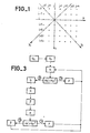
- the four curves in FIG. 2 relate to the values N of the sharpness indicator as a function of the position, L, of the lenses, and this for a given image and for gradients according to, respectively, the four directions indicated above. . From these curves it follows that, if the position of the lenses corresponding to the main peak is the same whatever the gradient considered, on the other hand the positions of the lenses corresponding to the secondary peaks, parasites vary according to the gradient considered.
- FIG. 2 relates to the different stages of an adjustment, according to the invention, of the lenses of a television camera.
- Figure 2 shows, from top to bottom, the curves corresponding to the gradient in the horizontal direction, H, in the vertical direction, V, in the diagonal Dl and in the diagonal D2.
- the position L of the lenses is arbitrary, the sharpness indicator operates with any gradient of direction which will be assumed to be the horizontal direction.
- the sharpness indicator provides an N0 value, the lenses. are moved, for example towards the front of the camera, over a short distance; this displacement which will always have the same amplitude and of which only the direction can vary, will be called, in what follows, unitary displacement.
- the sharpness indicator After this first unit displacement, identified by an arrow f 1 on the gradient curve H, the sharpness indicator provides a value NI greater than NO which indicates that the unit displacement seems to have taken place in the direction of an improvement in development.
- the second movement is therefore in the same direction (arrow f2) and the indicator continues to use the gradient H to provide a new value, N2, relating to the position reached.
- This value N2 being less than NI, the lenses are not moved and the indicator is controlled to provide a value N2 ', but this time with a new gradient which, in the example described, is the gradient V (second curve of Figure 2); this operation is intended to check whether the peak indicated by the value N2 lower than NI is or is not the main peak on which the focus must be focused.
- the direction of movement is again reversed and a fourth movement (arrow f4) leads to a value N4 greater than N3.
- the value N5 being greater than the value N4, a sixth displacement (arrow f6) is carried out, always without changing direction and gradient.
- the value N6 being less than the value N5 it is necessary, as in the case where N2 was less than N1, to check whether the peak encountered is a main peak or not; for this, as in the previous case, the gradient is changed for the indicator (third curve in Figure 2), a new value N6 'is provided by the indicator without the lenses having been moved, then the lenses are moved in the opposite direction to the previous movement (arrow f7), which leads to a value N7 at the output of the indicator.
- the value N7 being less than the value N6 'the peak found can be considered as a parasitic peak.
- a displacement ( fl3) not preceded by a change of direction is therefore carried out, which leads to a value N13 lower than N12 hence a change in gradient which brings back to the gradient horizontal direction (first curve in Figure 2); in short, the operations are then as follows: obtaining N13 ', displacement with change of direction, f14, obtaining N14 greater than N13', displacement without changing direction f15, obtaining N15 less than N14, change of gradient (vertical direction) , obtaining N15 ', displacement with change of direction, f16, obtaining N16 greater than N15', displacement without changing direction, f17, obtaining N17 less than N16, changing the gradient (direction DI), obtaining N17 ', displacement with change of direction, f18, obtaining N18 greater than N17 ', displacement without changing direction, f19, obtaining N19 less than N18, etc.
- Figures 4 and 5 are diagrams showing two parts of a device according to the invention for the development of a camera.
- the device that served as a model was designed for a camera operating at 625 lines per image with an eight-bit binary coded video signal. and whose sampling frequency is 10.125 MHz; as for the window in which the sharpness indicator calculates its value, its dimensions have been chosen equal to 32 by 32 points, it being understood that the points are those of the sampling.
- K is the sampling signal
- Pt the frame synchronization signal extended over the entire duration of the frame and formed of Ptl, extended odd frame synchronization signal, and Pt2, extended pair frame synchronization signal
- p the line synchronization signal
- n and m the signals representative respectively of the rank of the first row and of the first window column
- Sf the analysis window signal after storage and reading of the memory
- G the gradient change control signal for calculating the indicator
- A a predetermined signal
- Vg a gradient validation signal.
- FIG. 4 shows a block 1, called VIDEO, which symbolizes the circuits for obtaining the video signal from a television camera and the sampling circuits for providing a sampled signal, digitized on eight bits.
- VIDEO a block 1, called VIDEO, which symbolizes the circuits for obtaining the video signal from a television camera and the sampling circuits for providing a sampled signal, digitized on eight bits.
- the multiple conductors are indicated by a small line which cuts the conductor and beside which a number gives the number of single conductors, in parallel, which it comprises; thus it is indicated that the output conductor of the VIDEO block comprises eight single conductors.
- the digitized signals corresponding to the window of the image in which the calculation of the indicator mentioned above is carried out, are stored, for the even frames and the odd frames, respectively in two memories 2 and 3; memories 2 and 3 are controlled by signals Ptl and Pt2 so as to be one in the reading phase and the other in the writing phase during a frame and the reverse during the next frame.
- the indicator analysis window is defined using circuits 50 to 59 in FIG. 4.
- a counter 50 which receives the line synchronization signal p as a counting signal and the signal as reset signal Frame synchronization point, is connected to one of the inputs of a comparator 54, the other input of which receives the signal n representative of the rank of the first line of the window; the comparator 54 supplies an AND gate 58 with a signal the ne at the last line of each frame.
- a counter 51 which receives as signal count signal p and as reset signal signal Pt, is authorized to count by the signal of comparator 54; a comparator 55 receives on one input the output signal of the counter 51 and on another input the signal corresponding to the signal of the counter 51 when the count reached is equal to 32; comparator 55 supplies the AND gate 58 with a signal from the first to the (n + 32) th line of each frame.
- a counter 52 which receives the sampling signal K as the counting signal and the signal p as the reset signal, is authorized to count only when the output signal from the comparator 54 is at logic level 1; a comparator 56 receives on one input the output signal of the counter 52 and on another input the signal m representative of the rank of the first column of the window; from the not line of each field the comparator 56 provides the AND gate 58 a signal for all the points of the m-th to the last column of the frame.
- a counter 53 which receives the signal K as the counting signal and the signal p as the reset signal, is authorized to count only when the output signal from the comparator 56 is at logic level 1; a comparator 57 receives on one input the output signal of the counter 53 and on another input the signal corresponding to the signal of the counter 53 when the count reached is equal to 32; as long as comparator 56 provides an output signal comparator 57 itself provides an output signal for all points up to the (m + 32) th column of the frame.
- the AND gate 58 of FIG. 4 therefore supplies, as a function of its input signals, a signal which is at logic level 1 during, and only during the analysis window of each frame; this signal serves as an authorization signal for a counter 59 whose counting signal is the signal K and whose reset signal is the signal Pt.
- the counter 59 thus provides a counting signal which progresses from 1 to 32 2 for the duration of each window.
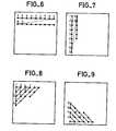
- Figures 6 to 9 show, reduced to a window of 9 by 9 points to simplify the drawing, in which order should the points of the window be taken according to the type of gradient which is chosen for the calculation by the sharpness indicator; in these figures have been represented only the first points used for the calculation, with, next to each of these points, a serial number relating to this point.
- the order of the points corresponds to their order of preparation by the camera, there is therefore no need for transposition using a memory; this is the case where the gradient chosen is the horizontal gradient.
- a switch 70 controlled by the signal Pt, has two inputs connected respectively to the output of the switch 63 and to the output of the counter 59, to deliver, every other frame, a write signal to memory 2 and a signal read to memory 3 and the reverse to the next frame.
- the write signal is the output signal from the switch 63 and the read signal is the output signal from the counter 59, applied directly to an input of the switch 70.
- a switch 4 controlled by the signal Pt receives and delivers, every other frame, the read signal from memory 2 and, the next frame, the read signal from memory 3.
- the signal Sf is used, in the circuit according to Figure 5, to provide the sharpness indication signal and to adjust the position of the objective lenses of the television camera.
- the gradient used for the calculation of the indicator is obtained by difference, in absolute value, between two consecutive values provided by that of the two memories 2, 3, of FIG. 4, which is read.
- the absolute value is obtained by selecting the value of the difference complemented with 2 if this value is negative or of this difference if this value is positive.
- the assembly of _figure 6 comprises an adder 10 which receives the signal Sf from a point in the window, at the same time as it receives on the one hand the signal Sf from the previous point inverted thanks to a buffer register, 11 , controlled by the sampling signal and followed by an inverter 12 and on the other hand a logic 1.
- the output signal of the adder 10 is applied directly to a first signal input of a switch 22 and is also applied to a second signal input of this switch, through an inverter 20 followed by an adder 21 which receives also a logical 1; the selection by the switch 22 between the value supplemented by 2 supplied by the adder 21 and the difference supplied by the adder 10, is made by command of the switch 22 by means of the signal for exceeding the value 11111111 by the adder 10 .
- the horizontal gradient validation is obtained from a decoding using a decoder circuit 64 which receives the signals from the counter 59 and indicates to the switch 63 when a difference which is to be calculated must be eliminated (for example for the point 10. of figure 6).
- the signals are added in an adder 5 and stored in a register 6, at the sampling frequency K.
- the value obtained at the end of the frame is firstly supplied directly to an input of a comparator 40 and on the other hand, through a buffer register 7 whose read control input receives the signal Pt, to another input of comparator 40.
- Comparator 40 thus directly receives from registers 6 and 7 what had been called respectively last and penultimate value provided by the indicator, in the flowchart according to Figure 3.
- a 3 by 5 read-only memory 41 receives the output signal from the comparator 40 and is connected by its output to the input of a buffer register 42 whose read control input receives the signal Pt. Two of the conductors of output of register 42 go to the input of memory 41, while a conductor goes to the input of a counter 8 which supplies the signal G of change of gradient and that two conductors go to input d a pulse generator, 9, which supplies forward and reverse pulses to a stepping motor, M, which drives the camera lens adjustment lenses, B.
- the pulses of the two pulse circuits are delayed and, for to advance the motor M, it is the delayed positive pulse which is used if the counter is at 1 and for the delayed negative pulse which is used if the counter is at zero.
- the invention is not limited to the example described, it is thus, in particular, that in phase 1 of the flowchart according to FIG. 3 it can be provided, after the change of gradient (block G) and before calculating the indicator (block N), a unit displacement of the lenses in the opposite direction to the preceding displacement.
- the stepping motor, M, used to move the lenses can be replaced by any other conventional servo motor suitably chosen and controlled; for example a DC motor, on the shaft of which an encoder disc would be mounted to identify its angular position, can be used.
- the calculation of the value of the sharpness indicator it can be done by any editing capable of giving a signal representative of the sharpness of at least part of the image.
- the analysis window of the sharpness indicator can cover the entire television image provided by the camera; in this case the circuits 50 to 58 of FIG. 4 are useless and the counter 59 counts for the whole duration of a frame; the problem is that then the size of memories 2, 3 and 60, 61, 62 becomes very large.
Abstract
Description
La présente invention se rapporte à la mise au point automatique de caméras de télévision.The present invention relates to the automatic focusing of television cameras.
Il est connu de commander le moteur d'entraînement des lentilles de mise au point d'une caméra de télévision en fonction de la quantité de hautes fréquences contenues dans l'image, cette quantité étant calculée à l'aide d'un indicateur de netteté. Pour cela la position des lentilles est modifiée de façon lente et périodique, par des déplacements ayant généralement tous la même amplitude ; l'image est déclarée nette quand la valeur fournie par l'indicateur passe par un maximum. Lorsque l'image analysée présente une structure spatiale plus ou moins périodique comme, par exemple, des bandes parallèles, cette façon de procéder peut conduire à un réglage incorrect ; en effet la courbe de la valeur de l'indicateur en fonction de la position des lentilles, fait apparaître un pic principal et un ou plusieurs pics secondaires or c'est sur un de ces pics secondaires dus à la structure périodique de l'image que risque de se faire le réglage. Comme l'amplitude en fonction de la position des lentilles., varie fortement avec les fréquences spatiales de l'image étudiée, il n'est pas possible de déterminer, grâce à un seuil, quel est le pic principal c'est-à-dire le pic sur lequel doit s'effectuer le réglage. Quant à l'exploration systématique de toute la courbe, suivie d'un retour à la position correspondant au pic d'amplitude maximale, elle est relativement longue et produit un effet de trainage important dans l'image.It is known to control the drive motor for the focusing lenses of a television camera as a function of the quantity of high frequencies contained in the image, this quantity being calculated using a sharpness indicator. . For this, the position of the lenses is modified slowly and periodically, by displacements generally having all the same amplitude; the image is declared sharp when the value provided by the indicator goes through a maximum. When the analyzed image has a more or less periodic spatial structure such as, for example, parallel bands, this way of proceeding can lead to an incorrect adjustment; in fact the curve of the value of the indicator as a function of the position of the lenses, shows a main peak and one or more secondary peaks, but it is on one of these secondary peaks due to the periodic structure of the image that risk of being adjusted. As the amplitude as a function of the position of the lenses., Varies greatly with the spatial frequencies of the image studied, it is not possible to determine, using a threshold, what is the main peak, that is to say say the peak on which the adjustment should be made. As for the systematic exploration of the entire curve, followed by a return to the position corresponding to the maximum amplitude peak, it is relatively long and produces a significant drag effect in the image.
La présente invention a pour but d'éviter ou pour le moins de réduire les inconvénients des dispositifs de mise au point basés sur une étude de la quantité de hautes fréquences contenues dans l'image de la caméra.The present invention aims to avoid or at least reduce the drawbacks of focusing devices based on a study of the quantity of high frequencies contained in the image of the camera.
Ceci est obtenu à l'aide d'un indicateur de netteté permettant une étude selon au moins deux axes différents, de la structure spatiale de l'image et par une vérification de l'obtention du pic principal, basée sur une étude effectuée au moins selon deux des axes différents.This is obtained using a sharpness indicator allowing a study along at least two different axes, of the spatial structure of the image and by a verification of the obtaining of the main pi c , based on a study carried out at less along two different axes.
Selon l'invention un procédé de mise au point de l'objectif d'une caméra de télévision à partir de valeurs N = Σ g(i,j) , où F est une (i,j)EF fenêtre d'analyse contenue dans l'image analysée, où (i,j) est un point de la fenêtre d'analyse et où g(i,j) est un gradient de la valeur X(i,j) du signal vidéo de la trame de télévision délivrée par la caméra, ce procédé consistant à effectuer des déplacements unitaires systématiques des lentilles de l'objectif, à comparer, pour chaque position des lentilles, la valeur N avec la valeur N de la position précédente et à rechercher une valeur maximale de N, est caractérisé en ce qu'il consiste à choisir le gradient considéré parmi deux ou moins des quatre gradients X(i,j) - X(i,j-l), X(i,j) - X(i-1), X(l,j) - X(i-l, j-1), X(i,j) - X(i,j,j+1) et, lorsqu'une valeur de N maximale est trouvée, avec un premier des gradients, autour d'une position donnée des lentilles, à vérifier que cette position donnée est celle de mise au point en recherchant autour de la position donnée, une autre valeur de N maximale, avec au moins un des gradients autre que le premier.According to the invention a method of developing the objective of a television camera from values N = Σ g (i, j), where F is an (i, j) E F contained analysis window in the analyzed image, where (i, j) is a point in the analysis window and where g (i, j) is a gradient of the value X (i, j) of the video signal of the delivered television frame by the camera, this method consisting in carrying out systematic unitary displacements of the objective lenses, in comparing, for each position of the lenses, the value N with the value N of the previous position and in searching for a maximum value of N, is characterized in that it consists in choosing the gradient considered from two or less of the four gradients X (i, j) - X (i, jl), X (i, j) - X (i-1), X (l , j) - X (il, j-1), X (i, j) - X (i, j, j + 1) and, when a value of maximum N is found, with a first of the gradients, around d '' a given position of the lenses, to check that this given position is that of focusing by looking around from the given position, another maximum value of N, with at least one of the gradients other than the first.
La présente invention sera mieux comprise et d'autres caractéristiques apparaîtront à l'aide de la description ci-après et des figures s'y rapportant qui représentent :.
- - la figure 1 un schéma relatif à des points d'analyse d'une image fournie par une caméra de télévision,
- - la figure 2, un schéma montrant comment, selon l'invention, est effectuée la mise au point d'une caméra de télévision,
- - la figure 3, un organigramme du procédé de mise au point,
- - les figures 4 et 5, des schémas d'un dispositif pour la mise au point dune caméra de télévision.
- - les figures 6 à 9 des dessins expliquant le fonctionnement d'un ensemble de mémoires de la figure 4.
- FIG. 1 a diagram relating to analysis points of an image supplied by a television camera,
- FIG. 2, a diagram showing how, according to the invention, the development of a television camera is carried out,
- FIG. 3, a flow diagram of the development process,
- - Figures 4 and 5, diagrams of a device for the development of a television camera.
- - Figures 6 to 9 of the drawings explaining the operation of a set of memories in Figure 4.
Dans la suite de la description il va être question d'un indicateur de netteté qui sera aussi appelé indicateur ; il s'agira d'un appareil de mesure destiné à recevoir tout ou partie du signal vidéo produit par une caméra de télévision et qui fournit un signal N de la forme .
où i, j sont les coordonnées d'un point de l'image situé à la ligne i et à la colonne j, où F est une fenêtre d'analyse prédéterminée contenue dans l'image fournie par la caméra et où g(i,j) est un gradient de la quantité de hautes fréquences, X, contenues dans le signal vidéo de la caméra.where i, j are the coordinates of a point of the image located at line i and at column j, where F is a predetermined analysis window contained in the image supplied by the camera and where g (i, j) is a gradient of the quantity of high frequencies, X, contained in the video signal of the camera.
Dans l'art antérieur il était connu de déterminer ce gradient selon les horizontales de l'image, ce qui consistait, mais en analogique, à prendre un signal représentatif de X(i,j) - X(i,j-1). Comme il a été indiqué plus avant, la courbe de la valeur fournie par l'indicateur en fonction de la position des lentilles peut présenter des pics secondaires dus à une structure périodique de l'image, ce qui est très gênant pour la mise au point. Or des mesures faites par l'inventeur ont permis de montrer que la courbe de la valeur fournie par l'indicateur en fonction de la position des lentilles était différente selon la direction dans laquelle était déterminée la gradient ; la figure 1, relative à une fenêtre de points d'analyse de l'image d'une caméra de télévision, permet de mieux saisir cette notion de gradients différents dans l'image de télévision.In the prior art it was known to determine this gradient according to the horizontal of the image, which consisted, but in analog, in taking a signal representative of X (i, j) - X (i, j-1). As indicated above, the curve of the value provided by the indicator as a function of the position of the lenses may have secondary peaks due to a periodic structure of the image, which is very troublesome for focusing. . However, measurements made by the inventor have made it possible to show that the curve of the value provided by the indicator as a function of the position of the lenses was different according to the direction in which the gradient was determined; FIG. 1, relating to a window for analysis points of the image of a television camera, makes it possible to better grasp this notion of different gradients in the television image.
La figure 1 montre des points d'une image analysée, répartis en sept lignes i - 2 à i+4 et sept colonnes j - 2 à j + 4. En appelant X(l,j) la quantité de hautes fréquences relative au point i,j, la valeur N, fournie par l'indicateur de netteté, peut être déterminée en prenant pour le gradient g(i,j) :
- soit g(i,j) = gH = X(i,j) - X(i,j - 1) gradient horizontal selon la direction H sur la figure 1,
- soit g(i,j) = gV = X(i,j) - X(i - l,j) gradient vertical, selon la direction V sur la figure 1,
- soit g(i,j) = gDl = X(i,j) - X(i-1, j - 1) gradient de diagonale + 45°, selon la direction Dl sur la figure 1,
- soit g(i,j) = gD2 = X(i,j) - X(i - 1, j +1) gradient de diagonale - 45°, selon la direction D2 sur la figure 1.
- let g (i, j) = gH = X (i, j) - X (i, j - 1) horizontal gradient in direction H in Figure 1,
- let g (i, j) = gV = X (i, j) - X (i - l, j) vertical gradient, in the direction V in Figure 1,
- either g (i, j) = gDl = X (i, j) - X (i-1, j - 1) diagonal gradient + 45 °, in the direction Dl in Figure 1,
- let g (i, j) = gD2 = X (i, j) - X (i - 1, j +1) diagonal gradient - 45 °, in the direction D2 in figure 1.
Les quatre courbes de la figure 2 sont relatives aux valeurs N de l'indicateur de netteté en fonction de la position, L, des lentilles, et ceci pour une image donnée et pour des gradients selon, respectivement, les quatre directions indiquées ci-avant. De ces courbes il résulte que, si la position des lentilles correspondant au pic principal est la même quelle que soit le gradient considéré, par contre les positions des lentilles correspondant aux pics secondaires, parasites varient en fonction du gradient considéré. L'expérience montre que la probabilité d'avoir une position des lentilles à laquelle correspondrait un pic secondaire pour chacun des quatre gradients mentionnés ci-avant est pratiquement nulle ; cette particularité est mise à profit, dans l'invention, pour vérifier, quand un pic apparaît, s'il s'agit d'un pic principal qui se retrouve au même point de réglage des lentilles pour les quatre gradients ou s'il s'agit d'un pic secondaire qui ne correspond pas à une position de réglage correct des lentilles.The four curves in FIG. 2 relate to the values N of the sharpness indicator as a function of the position, L, of the lenses, and this for a given image and for gradients according to, respectively, the four directions indicated above. . From these curves it follows that, if the position of the lenses corresponding to the main peak is the same whatever the gradient considered, on the other hand the positions of the lenses corresponding to the secondary peaks, parasites vary according to the gradient considered. Experience shows that the probability of having a lens position to which a secondary peak corresponds for each of the four gradients mentioned above is practically zero; This feature is used in the invention to check, when a peak appears, if it is a main peak which is found at the same lens adjustment point for the four gradients or if it s 'acts of a secondary peak which does not correspond to a position of correct adjustment of the lenses.
La figure 2 est relative aux différentes étapes d'un réglage, selon l'invention, des lentilles d'une caméra de télévision. La figure 2 montre, de haut en bas, les courbes correspondant au gradient dans le sens horizontal, H, dans le sens vertical, V, dans la diagonale Dl et dans la diagonale D2. Au départ de l'opération de réglage des lentilles, la position L des lentilles est quelconque, l'indicateur de netteté fonctionne avec un gradient de direction quelconque qui sera supposée être la direction horizontale. L'indicateur de netteté fournit une valeur N0, les lentilles . sont déplacées, par exemple vers Pavant de la caméra, sur une faible distance; ce déplacement qui aura toujours la même amplitude et dont seul le sens pourra varier, sera appelé, dans ce qui suit, déplacement unitaire. Après ce premier déplacement unitaire, repéré par une flèche fl sur la courbe de gradient H, l'indicateur de netteté fournit une valeur NI supérieure à NO ce qui indique que le déplacement unitaire semble s'être effectué dans le sens d'une amélioration de la mise au point. Le deuxième déplacement se fait donc dans le même sens (flèche f2) et l'indicateur continue d'utiliser le gradient H pour fournir une nouvelle valeur, N2, relative à la position atteinte. Cette valeur N2 étant inférieure à NI, les lentilles ne sont pas déplacées et l'indicateur est commandé pour fournir une valeur N2', mais cette fois avec un nouveau gradient qui, dans l'exemple décrit, est le gradient V (deuxième courbe de la figure 2) ; cette opération est destinée à vérifier si le pic qu'indique la valeur N2 inférieure à NI est ou n'est pas le pic principal sur lequel doit se faire la mise au point. Un troisième déplacement (flèche f3) dans le sens inverse des deux précédents, conduit à une valeur N3 de l'indicateur, inférieure à la valeur N2', ce qui montre que le pic était un pic parasite. Le sens de déplacement est à nouveau inversé et un quatrième déplacement (flèche f4) conduit à une valeur N4 supérieure à N3. La valeur de N ayant augmenté, un cinquième déplacement (flèche f5) est effectué sans changer de sens et de gradient par rapport à l'étape précédente. La valeur N5 étant supérieure à la valeur N4, un sixième déplacement (flèche f6) est effectué, toujours sans changer de sens et de gradient. La valeur N6 étant inférieure à la valeur N5 il faut, comme dans le cas où N2 était inférieur à N1, vérifier si le pic rencontré est un pic principal ou non ; pour cela, comme dans le cas précédent, le gradient est changé pour l'indicateur (troisième courbe de la figure 2), une nouvelle valeur N6' est fournie par l'indicateur sans que les lentilles aient été déplacées, puis les lentilles sont déplacées dans le sens inverse du déplacement précédent (flèche f7), ce qui conduit à une valeur N7 à la sortie de l'indicateur. La valeur N7 étant inférieure à la valeur N6' le pic trouvé peut être considéré comme un pic parasite. Sans changer de gradient mais en changeant de sens de déplacement (déplacement vers l'avant de la caméra) des déplacements successifs sont effectués (flèches f8 à fll) jusqu'à ce que soit trouvée une valeur de N inférieure à la valeur précédente ; c'est la valeur N11. A nouveau il faut vérifier si le pic trouvé est ou n'est pas le pic principal. Comme dans les cas précédents, le gradient de l'indicateur est changé (quatrième courbe de la figure 2), l'indicateur de netteté donne une valeur N11' ; un déplacement, dans le sens inverse du déplacement précédent, est effectué (flèche f12) qui amène une valeur N12 à la sortie de l'indicateur ; la valeur N12 étant supérieure à Nll' il semble que le pic trouvé est bien le pic principal et que les lentilles sont correctement réglées. Néanmoins le processus de réglage est poursuivi comme dans tous les cas précédents où la nouvelle valeur donnée par l'indicateur était supérieure à la précédente ; il y a deux raisons à cela : d'une part vérifier avec les autres gradients que les pics trouvés ne sont pas deux pics parasites qui auraient sensiblement la même abscisse respectivement sur la troisième et la quatrième courbe de la figure 2 et d'autre part être prêt à vérifier le réglage, si nécessaire, c'est-à-dire dans le cas où la modification de l'image conduirait à un déplacement de l'abscisse du pic principal sur les quatre courbes de la figure 2. Un déplacement (fl3) non précédé d'un changement de sens est donc effectué, qui conduit à une valeur N13 inférieure à N12 d'où un changement de gradient qui ramène au gradient de direction horizontale (première courbe de la figure 2) ; en bref les opérations sont alors les suivantes : obtention N13', déplacement avec changement de sens, f14, obtention de N14 supérieur à N13', déplacement sans changement de sens f15, obtention de N15 inférieur à N14, changement de gradient (direction verticale), obtention de N15', déplacement avec changement de sens, f16, obtention de N16 supérieur à N15', déplacement sans changement de sens, f17, obtention de N17 inférieur à N16, changement de gradient (direction DI), obtention de N17', déplacement avec changement de sens, f18, obtention de N18 supérieur à N17', déplacement sans changement sens, f19, obtention de N19 inférieur à N18, etc...FIG. 2 relates to the different stages of an adjustment, according to the invention, of the lenses of a television camera. Figure 2 shows, from top to bottom, the curves corresponding to the gradient in the horizontal direction, H, in the vertical direction, V, in the diagonal Dl and in the diagonal D2. At the start of the lens adjustment operation, the position L of the lenses is arbitrary, the sharpness indicator operates with any gradient of direction which will be assumed to be the horizontal direction. The sharpness indicator provides an N0 value, the lenses. are moved, for example towards the front of the camera, over a short distance; this displacement which will always have the same amplitude and of which only the direction can vary, will be called, in what follows, unitary displacement. After this first unit displacement, identified by an
Il est à remarquer que, dans le cas de la figure 2, différentes valeurs sont égales entre elles : N2' = N4, N6' = N8, N9 = N17', N10 = N18 et N11 = N19; ceci est dû à ce qu'il est supposé, par exemple pour NT = N4, que, entre le début du déplacement f3 et la fin du déplacement f4 la structure de l'image n'a pas varié et que les déplacements f3 e f4 - sont exactement de même amplitude.Note that, in the case of Figure 2, different values are equal to each other: N2 '= N4, N6' = N8, N9 = N17 ', N10 = N18 and N11 = N19; this is due to the fact that it is assumed, for example for NT = N4, that between the start of the displacement f3 and the end of the displacement f4 the structure of the image has not varied and that the displacements f3 e f4 - are of exactly the same amplitude.
La figure 3 est un organigramme du procédé de mise au point dont un exemple d'utilisation vient d'être décrit à l'aide de la figure 2. Dans cet organigramme les signes utilisés représentent respectivement :
- Na : la valeur fournie par l'indicateur de netteté au moment de la mise en route (position des lentilles et gradient arbitraires),
- Pa : déplacement unitaire dans un sens arbitraire,
- N : valeur fournie par l'indicateur à un moment donné, NdNp9: la dernière valeur, Nd, fournie par l'indicateur est-elle supérieure à l'avant dernière, Np9- la réponse est figurée par un V couché dans un cercle pour le OUI et par un V couché dans un cercle barré pour le NON,
- P : déplacement unitaire dans le même sens que le déplacement précédent,
- P : déplacement unitaire dans le sens inverse de celui du déplacement précédent,
- G : changement de gradient.
- Na: the value provided by the sharpness indicator at the start-up (position of the lenses and arbitrary gradient),
- Pa: unit displacement in an arbitrary direction,
- N: value provided by the indicator at a given time, NdNp 9 : is the last value, Nd, provided by the indicator greater than the penultimate, Np 9 - the answer is represented by a lying V in a circle for YES and by a V lying in a crossed-out circle for NO,
- P: unit displacement in the same direction as the previous displacement,
- P: unit displacement in the opposite direction to that of the preceding displacement,
- G: gradient change.
L'organigramme selon la figure 3 se compose d'une initialisation suivie de trois phases :The flowchart according to Figure 3 consists of an initialization followed by three phases:
(position des lentilles et gradient arbitraires) - calcul de l'indicateur de netteté,
phase 1 si la dernière valeur fournie par l'indicateur est supérieure à l'avant-dernière
alors .- - déplacement unitaire des lentilles dans le même sens que le déplacement précédent,
- - calcul de l'indicateur,
- - retour au début de la
phase 1,
sinon- - changement de gradient,
- - calcul de l'indicateur,
- - aller en
phase 2,
- -
phase 2- - déplacement unitaire des lentilles dans le sens inverse du déplacement précédent,
- - calcul de l'indicateur,
- - aller en
phase 3,
phase 3 si la dernière valeur fournie par l'indicateur est supérieure à l'avant-dernière
alors- - déplacement unitaire des lentilles dans le même sens que le déplacement précédent,
- - calcul de l'indicateur,
- - aller en
phase 1,
sinon- - - déplacement unitaire des lentilles dans le sens inverse du déplacement précédent,
- - calcul de l'indicateur,
- - aller en
phase 1.
-
phase 1 if the last value provided by the indicator is greater than the penultimate
so .- - unit displacement of the lenses in the same direction as the previous displacement,
- - calculation of the indicator,
- - return to the start of
phase 1,
if not- - gradient change,
- - calculation of the indicator,
- - go to
phase 2,
- -
phase 2- - unit displacement of the lenses in the opposite direction to the preceding displacement,
- - calculation of the indicator,
- - go to
phase 3,
-
phase 3 if the last value provided by the indicator is greater than the penultimate
so- - unit displacement of the lenses in the same direction as the previous displacement,
- - calculation of the indicator,
- - go to
phase 1,
if not- - - unit displacement of the lenses in the opposite direction to the preceding displacement,
- - calculation of the indicator,
- - go to
phase 1.
Les figures 4 et 5 sont des schémas représentant deux parties d'un dispositif selon l'invention pour la mise au point d'une caméra. Le dispositif qui a servi de modèle a été conçu pour une caméra fonctionnant en 625 lignes par image avec un signal vidéo codé en binaire sur huit bits et dont la fréquence d'échantillonnage est de 10,125 MHz; quant à la fenêtre dans laquelle l'indicateur de netteté calcule sa valeur, ses dimensions ont été choisies égales à 32 par 32 points, étant entendu que les points sont ceux de l'échantillonnage. Sur les figures 4 et 5 différents signaux sont indiqués par des repères : K est le signal d'échantiIlonnage, Pt le signal de synchronisation de trame prolongé sur toute la durée de la trame et formé de Ptl, signal de synchronisation de trame impaire prolongé, et Pt2, signal de synchronisation de trame paire prolongé, p le signal de synchronisation de ligne, n et m les signaux représentatifs respectivement du rang de la première ligne et de la première colonne de la fenêtre, Sf le signal de fenêtre d'analyse après mise en mémoire et lecture de la mémoire, G le signal de commande de changement de gradient pour le calcul de l'indicateur, A un signal prédéterminé et Vg un signal de validation de gradient.Figures 4 and 5 are diagrams showing two parts of a device according to the invention for the development of a camera. The device that served as a model was designed for a camera operating at 625 lines per image with an eight-bit binary coded video signal. and whose sampling frequency is 10.125 MHz; as for the window in which the sharpness indicator calculates its value, its dimensions have been chosen equal to 32 by 32 points, it being understood that the points are those of the sampling. In FIGS. 4 and 5, various signals are indicated by marks: K is the sampling signal, Pt the frame synchronization signal extended over the entire duration of the frame and formed of Ptl, extended odd frame synchronization signal, and Pt2, extended pair frame synchronization signal, p the line synchronization signal, n and m the signals representative respectively of the rank of the first row and of the first window column, Sf the analysis window signal after storage and reading of the memory, G the gradient change control signal for calculating the indicator, A a predetermined signal and Vg a gradient validation signal.
La figure 4 montre un bloc 1, appelé VIDEO, qui symbolise les circuits d'obtention du signal vidéo d'une caméra de télévision et les circuits d'échantillonnage pour fournir un signal échantillonné, numérisé sur huit bits. Il est à noter que, sur les figures 4 et 5, les conducteurs multiples sont indiqués par un petit trait qui coupe le conducteur et à côté duquel un chiffre donne le nombre de conducteurs simples, en parallèle, qu'il comporte ; c'est ainsi qu'il est indiqué que le conducteur de sortie du bloc VIDEO comporte huit conducteurs simples. Les signaux numérisés, correspondant à la fenêtre de l'image dans laquelle est effectué le calcul de l'indicateur dont il a été question plus avant, sont stockés, pour les trames paires et les trames impaires, respectivement dans deux mémoires 2 et 3 ; les mémoires 2 et 3 sont commandées par les signaux Ptl et Pt2 de manière à être l'une en phase de lecture et l'autre en phase d'écriture pendant une trame et l'inverse pendant la trame suivante.FIG. 4 shows a
La fenêtre d'analyse de l'indicateur est définie à l'aide des circuits 50 à 59 de la figure 4. Un compteur 50, qui reçoit comme signal de comptage le signal p de synchronisation ligne et comme signal de remise à zéro le signal Pt de synchronisation trame, est relié à l'une des entrées d'un comparateur 54 dont l'autre entrée reçoit le signal n représentatif du rang de la première ligne de la fenêtre ;le comparateur 54 fournit à une porte ET 58 un signal de la ne à la dernière ligne de chaque trame. Un compteur 51, qui reçoit comme signal de comptage le signal p et comme signal de remise à zéro le signal Pt, est autorisé de compter par le signal du comparateur 54 ; un comparateur 55 reçoit sur une entrée le signal de sortie du compteur 51 et sur une autre entrée le signal correspondant au signal du compteur 51 quand le compte atteint est égal à 32 ; le comparateur 55 fournit à la porte ET 58 un signal de la première à la (n + 32)e ligne de chaque trame. Un compteur 52, qui reçoit comme signal de comptage le signal K d'échantillonnage et comme signal de remise à zéro le signal p, n'est autorisé de compter que lorsque le signal de sortie du comparateur 54 est au niveau logique 1 ; un comparateur 56 reçoit sur une entrée le signal de sortie du compteur 52 et sur une autre entrée le signal m représentatif du rang de la première colonne de la fenêtre ; à partir de la ne ligne de chaque trame le comparateur 56 fournit à la porte ET 58 un signal pour tous les points de la me à la dernière colonne de la trame. Un compteur 53, qui reçoit comme signal de comptage le signal K et comme signal de remise à zéro le signal p, n'est autorisé de compter que lorsque le signal de sortie du comparateur 56 est au niveau 1 logique ; un comparateur 57 reçoit sur une entrée le signal de sortie du compteur 53 et sur une autre entrée le signal correspondant au signal du compteur 53 quand le compte atteint est égal à 32 ; tant que le comparateur 56 fournit un signal de sortie le comparateur 57 fournit lui-même un signal de sortie pour tous les points jusqu'à la (m+32)e colonne de la trame.The indicator analysis window is defined using
La porte ET 58 de la figure 4 fournit donc, en fonction de ses signaux d'entrée, un signal qui est au niveau logique 1 pendant, et seulement pendant la fenêtre d'analyse de chaque trame ; ce signal sert de signal d'autorisation pour un compteur 59 dont le signal de comptage est le signal K et dont le signal de remise à zéro est le signal Pt. Le compteur 59 fournit ainsi un signal de comptage qui progresse de 1 à 322 pendant la durée de chaque fenêtre.The AND
Pour permettre le changement de gradient dans le calcul de l'indicateur de netteté, celle des deux mémoires 2, 3 qui est lue pour fournir les éléments de calcul, c'est-à-dire les valeurs X(i,j) dont il a été question plus avant, est adressée soit directement par le compteur 59 pour le gradient horizontal, soit par l'intermédiaire d'une mémoire ,morte choisie parmi trois 60, 61, 62 ; le choix entre les mémoires et le signal provenant directement du compteur 59, s'effectue à l'aide d'un commutateur 63 commandé par un signal G de changement de gradient qui sera précisé à l'aide de la figure 5.To allow the gradient change in the calculation of the sharpness indicator, that of the two
Les figures 6 à 9 montrent, réduit à une fenêtre de 9 par 9 points pour simplifier le dessin, dans quel ordre doivent être pris les points de la fenêtre selon le type de gradient qui est choisi pour le calcul par l'indicateur de netteté ; sur ces figures n'ont été représentés que les premiers points utilisés pour le calcul, avec, à côté de chacun de ces points, un numéro d'ordre relatif à ce point. Sur la figure 6 l'ordre des points correspond à leur ordre d'élaboration par la caméra, il n'y a donc pas besoin de transposition à l'aide d'une mémoire; c'est la cas où le gradient choisi est le gradient horizontal. Par contre sur les figures 7, 8 et 9 les points sont pris respectivement par colonnes, en zigzag à partir du coin en haut à gauche de la fenêtre et en zigzag à partir du coin en bas à droite de la fenêtre; les chiffres indiqués dans ces trois fenêtres correspondent aux adresses de stockage dans les mémoires 60 à 62 qui . servent respectivement pour le calcul selon le gradient vertical, V, selon la diagonale DI (voir figure 1) et selon la diagonale D2. Un commutateur 70, commandé par le signal Pt, comporte deux entrées reliées respectivement à la sortie du commutateur 63 et à la sortie du compteur 59, pour délivrer, une trame sur deux, un signal d'écriture à la mémoire 2 et un signal de lecture à la mémoire 3 et l'inverse à la trame suivante. Le signal d'écriture est le signal de sortie du commutateur 63 et le signal de lecture est le signal de sortie du compteur 59, appliqué directement sur une entrée du commutateur 70.Figures 6 to 9 show, reduced to a window of 9 by 9 points to simplify the drawing, in which order should the points of the window be taken according to the type of gradient which is chosen for the calculation by the sharpness indicator; in these figures have been represented only the first points used for the calculation, with, next to each of these points, a serial number relating to this point. In FIG. 6, the order of the points corresponds to their order of preparation by the camera, there is therefore no need for transposition using a memory; this is the case where the gradient chosen is the horizontal gradient. By cons on Figures 7, 8 and 9 the points are taken respectively by columns, zigzag from the top left corner of the window and zigzag from the bottom right corner of the window; the figures indicated in these three windows correspond to the addresses for storage in
Un commutateur 4, commandé par le signal Pt, reçoit et délivre, une trame sur deux, le signal de lecture de la mémoire 2 et, la trame suivante, le signal de lecture de la mémoire 3. Le signal Sf est utilisé, dans le circuit selon la figure 5, pour fournir le signal d'indication de netteté et permettre de régler la position des lentilles de l'objectif de la caméra de télévision.A
Dans le montage selon la figure 5 le gradient utilisé pour le calcul de l'indicateur est obtenu par différence, en valeur absolue, entre deux valeurs consécutives fournies par celle des deux mémoires 2, 3, de la figure 4, qui est lue. La valeur absolue est obtenue par sélection de la valeur de la différence complémentée à 2 si cette valeur est négative ou de cette différence si cette valeur est positive. Pour cela le montage de la _figure 6 comporte un additionneur 10 qui reçoit le signal Sf d'un point de la fenêtre, en même temps qu'il reçoit d'une part le signal Sf du point précédent inversé grâce à un registre tampon, 11, commandé par le signal d'échantillonnage et suivi d'un inverseur 12 et d'autre part un 1 logique. Le signal de sortie de l'additionneur 10 est appliqué directement à une première entrée de signal d'un commutateur 22 et est également appliqué à une deuxième entrée de signal de ce commutateur, à travers un inverseur 20 suivi d'un additionneur 21 qui reçoit également un 1 logique ; la sélection par le commutateur 22 entre la valeur complémentée à 2 fournie par l'additionneur 21 et la différence fournie par l'additionneur 10, se fait par commande du commutateur 22 au moyen du signal de dépassement de la valeur 11111111 par l'additionneur 10.In the assembly according to FIG. 5, the gradient used for the calculation of the indicator is obtained by difference, in absolute value, between two consecutive values provided by that of the two
Aux frontières de la fenêtre, deux adresses lues successivement ne correspondent pas à deux points consécutifs, les différences calculées sont erronées et doivent être éliminées ; c'est ainsi que dans le cas du gradient horizontal représenté sur la figure 6, les différences telles que celle entre le point 9 et le point 10 doivent être éliminées, de même que dans le cas du gradient vertical (figure 7) ; dans le cas du gradient selon la diagonale Dl (figure 8) ce sont les différences entre des points tels que 1 et 2, 3 et 4, 5 et 7, 10 et 11, qui doivent être éliminées de même que dans le cas du gradient selon la diagonale D2 (figure 9).At the borders of the window, two addresses read successively do not correspond to two consecutive points, the calculated differences are erroneous and must be eliminated; thus in the case of the horizontal gradient shown in Figure 6, differences such as that between
Un bit d'adresse supplémentaire (validation d'accumulation) doit donc signaler la validité des calculs.An additional address bit (validation of accumulation) must therefore indicate the validity of the calculations.
Il s'ensuit que le contenu des mémoires V, Dl, D2, respectivement notées 60, 61, 62, est codé par 11 bits: 10 bits d'adresse et 1 bit de validation du gradient qui prend la valeur 0 lorsque la différence qui va être calculée doit être éliminée (par exemple pour le point 10 de la figure 7 et pour le point 7 de la figure 8).It follows that the content of memories V, D1, D2, respectively denoted 60, 61, 62, is coded by 11 bits: 10 address bits and 1 gradient validation bit which takes the value 0 when the difference which will be calculated must be eliminated (for example for
La validation horizontale de gradient est obtenue à partir d'un décodage à l'aide d'un circuit décodeur 64 qui reçoit les signaux du compteur 59 et indique au commutateur 63 quand une différence qui va être calculée doit être éliminée (par exemple pour le point 10. de la figure 6).The horizontal gradient validation is obtained from a decoding using a
Le bit de validation, Vg, issu du commutateur 63, valide le gradient au niveau d'une porte 31 (figure 5).The validation bit, Vg, from
Pour éviter le bruit, la transmission du signal de sortie du comparateur 22 n'est autorisée par un circuit à seuil que si le signal est supérieur à un seuil prédéterminé. Le circuit à seuil comporte la porte 31, qui reçoit, outre le signal de validation Vg, le signal de sortie du commutateur 22 et qui ne le laisse passer que si Vg = 1 et si une valeur prédéterminée, A, appliquée à la première entrée d'un comparateur 30 est inférieure ou égale à la valeur du signal de sortie du commutateur 22.To avoid noise, the transmission of the output signal from
A la sortie du circuit à seuil les signaux sont additionnés dans un additionneur 5 et stockés dans un registre 6, à la fréquence d'échantillonnage K. La valeur obtenue en fin de trame est délivrée d'une part directement à une entrée d'un comparateur 40 et d'autre part, à travers un registre tampon 7 dont l'entrée de commande de lecture reçoit le signal Pt, à une autre entrée du comparateur 40. Le comparateur 40 reçoit ainsi directement des registres 6 et 7 ce qui avait été appelé respectivement dernière et avant-dernière valeur fournies par l'indicateur, dans l'organigramme selon la figure 3.At the output of the threshold circuit, the signals are added in an
Une mémoire morte, 41, de 3 par 5, reçoit le signal de sortie du comparateur 40 et est reliée par sa sortie à l'entrée d'un registre tampon 42 dont l'entrée de commande de lecture reçoit le signal Pt. Deux des conducteurs de sortie du registre 42 vont à l'entrée de la mémoire 41, tandis qu'un conducteur va à l'entrée d'un compteur 8 qui fournit le signal G de changement de gradient et que deux conducteurs vont à l'entrée d'un générateur d'impulsions, 9, qui fournit des impulsions de marche avant et de marche arrière à un moteur pas à pas, M, qui entraîne les lentilles de réglage de l'objectif de la caméra, B.A 3 by 5 read-
Les paramètres d'entrée de la mémoire 41 sont les suivants :
- résultat, C, de la comparaison, par le comparateur 4-0, entre la dernière et l'avant-dernière valeur fournie par l'indicateur C = 0 pour dernière valeur inférieure à avant-dernière valeur C = 1 pour dernière valeur supérieure à avant-dernière valeur.
- - description de l'état antérieur E E = 00 pour la phase 1 E = 01 pour la phase 2 E = 10 pour
la phase 3
- result, C, of the comparison, by the 4-0 comparator, between the last and the penultimate value provided by the indicator C = 0 for last value less than penultimate value C = 1 for last value greater than penultimate value.
- - description of the previous state EE = 00 for phase 1 E = 01 for phase 2 E = 10 for
phase 3
Les paramètres de sortie de la mémoire 41, délivrés à travers le registre 42 sont les suivants :
- - description de l'état actuel E
- E = 00 pour
la phase 1 - E = 01 pour
la phase 2 - E = 10 pour
la phase 3
- E = 00 pour
- - sens, D, de déplacement des lentilles
- D = 00 pas de déplacement
- D = 01 déplacement, P, des lentilles, sans changement de sens par rapport au déplacement précédent
- D = 10 déplacement, P, des lentilles avec changement de sens par rapport au déplacement précédent
- - commutation éventuelle, g, du type de gradient
- g = 0 pas de commutation
- g = 1 commutation.
- - description of the current state E
- E = 00 for
phase 1 - E = 01 for
phase 2 - E = 10 for
phase 3
- E = 00 for
- - direction, D, of movement of the lenses
- D = 00 no movement
- D = 01 displacement, P, of the lenses, without change of direction compared to the preceding displacement
- D = 10 displacement, P, of the lenses with change of direction compared to the preceding displacement
- - possible switching, g, of the gradient type
- g = 0 no switching
- g = 1 switching.
En fonction de la description du procédé de mise au point qui a été décrit à l'aide des figures 2 et 3, le contenu de la mémoire 41 qui assure le déroulement de ce procédé est donné par la correspondance ci-après entre les entrées en mémoire et les sorties de la mémoire :

ce qui se lit de façon plus détaillée, par exemple pour la première de ces six lignes : "si l'étape précédente s'est arrêtée au début d'une phase .1 (E = 00) et que la dernière valeur est inférieure à l'avant-dernière valeur fournie par l'indicateur (C = 0), alors il ne faut pas déplacer les lentilles (D = 00), mais il faut changer de gradient (g = 1) et aller en début de phase 2 (E = 01)".which reads in more detail, for example for the first of these six lines: "if the previous step stopped at the start of a phase .1 (E = 00) and the last value is less than the penultimate value provided by the indicator (C = 0), so do not move the lenses (D = 00), but you must change the gradient (g = 1) and go to the start of phase 2 ( E = 01) ".
Le générateur d'impulsions 9 comporte, pour réagir aux signaux D de déplacement, deux circuits à impulsions pour fournir respectivement une impulsion positive et une impulsion négative chaque fois qu'apparaît un signal D de valeur non nulle (D = 01 et D = 10) et un compteur modulo 2 qui avance d'une unité à chaque apparition d'un signal D = 10. Les impulsions des deux circuits à impulsions sont retardées et, pour faire avancer le moteur M, c'est l'impulsion positive retardée qui est utilisée si le compteur est à 1 et dest l'impulsion négative retardée qui est utilisée si le compteur est à zéro.The
L'invention n'est pas limitée à l'exemple décrit, c'est ainsi, en particulier, que dans la phase 1 de l'organigramme selon la figure 3 il peut être prévu, après le changement de gradient (bloc G) et avant le calcul de l'indicateur (bloc N), un déplacement unitaire des lentilles dans le sens inverse du déplacement précédent.The invention is not limited to the example described, it is thus, in particular, that in
De même le moteur pas à pas, M, utilisé pour déplacer les lentilles peut être remplacé par tout autre moteur d'asservissement classique convenablement choisi et commandé ; par exemple un moteur à courant continu, sur l'arbre duquel serait monté un disque codeur pour repérer sa position angulaire, peut être utilisé.Similarly the stepping motor, M, used to move the lenses can be replaced by any other conventional servo motor suitably chosen and controlled; for example a DC motor, on the shaft of which an encoder disc would be mounted to identify its angular position, can be used.
Quant au calcul de la valeur de l'indicateur de netteté, elle peut se faire par tout montage capable de donner un signal représentatif de la netteté d'au moins une partie de l'image. Il est à noter à ce sujet que la fenêtre d'analyse de l'indicateur de netteté peut couvrir toute l'image de télévision fournie par la caméra ; dans ce cas les circuits 50 à 58 de la figure 4 sont inutiles et le compteur 59 compte pendant toute la durée d'une trame; le problème est qu'alors la taille des mémoires 2, 3 et 60, 61, 62 devient très importante.As for the calculation of the value of the sharpness indicator, it can be done by any editing capable of giving a signal representative of the sharpness of at least part of the image. It should be noted in this regard that the analysis window of the sharpness indicator can cover the entire television image provided by the camera; in this case the
Il est également possible de simplifier le montage en réduisant, au maximum à deux, le nombre de gradients différents selon lesquels peut s'effectuer le calcul de l'indicateur par exemple en ne gardant que le gradient horizontal et le gradient vertical.It is also possible to simplify the assembly by reducing, to a maximum of two, the number of different gradients according to which the calculation of the indicator can be carried out, for example by keeping only the horizontal gradient and the vertical gradient.
Claims (5)
Applications Claiming Priority (2)
| Application Number | Priority Date | Filing Date | Title |
|---|---|---|---|
| FR8500108A FR2575888B1 (en) | 1985-01-04 | 1985-01-04 | METHOD AND DEVICE FOR DEVELOPING A CAMERA AND CAMERA COMPRISING SUCH A DEVICE |
| FR8500108 | 1985-01-04 |
Publications (2)
| Publication Number | Publication Date |
|---|---|
| EP0194162A1 true EP0194162A1 (en) | 1986-09-10 |
| EP0194162B1 EP0194162B1 (en) | 1990-10-03 |
Family
ID=9315023
Family Applications (1)
| Application Number | Title | Priority Date | Filing Date |
|---|---|---|---|
| EP86400007A Expired - Lifetime EP0194162B1 (en) | 1985-01-04 | 1986-01-03 | Method and device for focussing in a camera, and camera comprising such a device |
Country Status (3)
| Country | Link |
|---|---|
| EP (1) | EP0194162B1 (en) |
| DE (1) | DE3674600D1 (en) |
| FR (1) | FR2575888B1 (en) |
Cited By (3)
| Publication number | Priority date | Publication date | Assignee | Title |
|---|---|---|---|---|
| EP0290802A2 (en) * | 1987-05-15 | 1988-11-17 | Polaroid Corporation | Focusing system for camera apparatus |
| EP0318278A2 (en) * | 1987-11-25 | 1989-05-31 | Matsushita Electric Industrial Co., Ltd. | Automatic focusing apparatus |
| EP0507627A2 (en) * | 1991-04-03 | 1992-10-07 | Sharp Kabushiki Kaisha | Automatic focusing device and method |
Families Citing this family (2)
| Publication number | Priority date | Publication date | Assignee | Title |
|---|---|---|---|---|
| JPH09168113A (en) * | 1995-06-05 | 1997-06-24 | Sony Corp | Automatic focus device |
| US6310982B1 (en) | 1998-11-12 | 2001-10-30 | Oec Medical Systems, Inc. | Method and apparatus for reducing motion artifacts and noise in video image processing |
Citations (2)
| Publication number | Priority date | Publication date | Assignee | Title |
|---|---|---|---|---|
| EP0031483A1 (en) * | 1979-12-26 | 1981-07-08 | Hughes Aircraft Company | Closed loop autofocus system |
| US4422097A (en) * | 1980-03-19 | 1983-12-20 | Fuji Photo Film Co., Ltd. | Automatic focus controlling method |
-
1985
- 1985-01-04 FR FR8500108A patent/FR2575888B1/en not_active Expired
-
1986
- 1986-01-03 EP EP86400007A patent/EP0194162B1/en not_active Expired - Lifetime
- 1986-01-03 DE DE8686400007T patent/DE3674600D1/en not_active Expired - Fee Related
Patent Citations (2)
| Publication number | Priority date | Publication date | Assignee | Title |
|---|---|---|---|---|
| EP0031483A1 (en) * | 1979-12-26 | 1981-07-08 | Hughes Aircraft Company | Closed loop autofocus system |
| US4422097A (en) * | 1980-03-19 | 1983-12-20 | Fuji Photo Film Co., Ltd. | Automatic focus controlling method |
Cited By (8)
| Publication number | Priority date | Publication date | Assignee | Title |
|---|---|---|---|---|
| EP0290802A2 (en) * | 1987-05-15 | 1988-11-17 | Polaroid Corporation | Focusing system for camera apparatus |
| EP0290802A3 (en) * | 1987-05-15 | 1990-06-06 | Polaroid Corporation | Focusing system for camera apparatus |
| EP0318278A2 (en) * | 1987-11-25 | 1989-05-31 | Matsushita Electric Industrial Co., Ltd. | Automatic focusing apparatus |
| EP0318278A3 (en) * | 1987-11-25 | 1990-03-07 | Matsushita Electric Industrial Co., Ltd. | Automatic focusing apparatus |
| US4975726A (en) * | 1987-11-25 | 1990-12-04 | Matsushita Electric Industrial Co., Ltd. | Automatic focusing apparatus |
| EP0507627A2 (en) * | 1991-04-03 | 1992-10-07 | Sharp Kabushiki Kaisha | Automatic focusing device and method |
| EP0507627A3 (en) * | 1991-04-03 | 1993-03-24 | Sharp Kabushiki Kaisha | Automatic focussing device controlled by trend of variation and degree of reliability of a focussing evaluation value signal |
| US5337084A (en) * | 1991-04-03 | 1994-08-09 | Sharp Kabushiki Kaisha | Automatic focusing device utilizing a trend of variation and degree of reliability of a focusing evaluation value signal to improve image focusing |
Also Published As
| Publication number | Publication date |
|---|---|
| DE3674600D1 (en) | 1990-11-08 |
| FR2575888B1 (en) | 1987-02-20 |
| FR2575888A1 (en) | 1986-07-11 |
| EP0194162B1 (en) | 1990-10-03 |
Similar Documents
| Publication | Publication Date | Title |
|---|---|---|
| FR2523787A1 (en) | METHOD AND DEVICE FOR VIDEO PROCESSING FOR IMAGE ROTATION | |
| FR2524235A1 (en) | SPACE TRANSFORMATION SYSTEM COMPRISING A SIGNAL SIGNAL GENERATOR | |
| EP0033172B1 (en) | Circuit for correcting the phase differences between the deflection control signals and the synchronisation signals in a television receiver | |
| EP0146476A2 (en) | Device for stereoscopic pictures with a base-defining system | |
| FR2514530A1 (en) | METHOD FOR ENTERING DATA REPRESENTATIVE OF THE FORM OF AN OBJECT | |
| EP0194162B1 (en) | Method and device for focussing in a camera, and camera comprising such a device | |
| EP0018861A1 (en) | Method and device for numeric processing of video signals representative of a leaf-like product | |
| CH661624A5 (en) | METHOD AND APPARATUS FOR CONVERTING DIGITAL DATA. | |
| EP0272959B1 (en) | Process for playing back a recorded mobile scene, particularly using a video disc, and its use in driving simulators | |
| FR2654283A1 (en) | AUTOMATIC FOCUSING DEVICE FOR AN OPTICAL SYSTEM. | |
| FR2589302A1 (en) | INFRARED THERMOGRAPHY SYSTEM WITH IMPROVED SENSITIVITY BY PROGRESSIVE AMOUNTING OF IMAGE LINES | |
| FR2535561A1 (en) | VIDEO SIGNAL PROCESSING SYSTEM | |
| EP0034956B1 (en) | Television synchronization signal and test signal generator, and television system comprising such a generator | |
| FR2492201A1 (en) | ROTARY RECORDING MEDIUM REPRODUCING APPARATUS CAPABLE OF PERFORMING SPECIAL REPRODUCTION | |
| FR2614488A1 (en) | COLOR TELEVISION CAMERA WITH MULTIPLE TUBES HAVING AN AUTOMATIC COINCIDENCE ADJUSTMENT SYSTEM | |
| FR2684829A1 (en) | METHODS OF SYNTHESIZING TEXTURE SIGNALS AND TRANSMITTING AND / OR STORING SUCH SIGNALS, AND DEVICES AND SYSTEMS FOR THEIR IMPLEMENTATION. | |
| FR2509558A1 (en) | MULTI-TUBE COLOR TELEVISION CAMERA | |
| FR2527802A1 (en) | INCREMENTIAL-TO-DIGITAL CONVERTER | |
| EP0029390B1 (en) | Microfiche reader | |
| EP1037204B1 (en) | Servo system and method to servo a beam incident on a moving data carrier in particular a digital disc | |
| EP0690623B1 (en) | Method of and device for inserting asynchronous data into a digital signal | |
| EP0393763A1 (en) | Method for correcting offset dispersions in photoelectric sensors and correcting device therefor | |
| FR2507419A1 (en) | Object identification using video image - uses two memories and analysis on cartesian grid to identify contour outline of object | |
| EP0640910B1 (en) | Control process for a first in - first out circuit and device to carry it out | |
| EP0235002A1 (en) | Charge transfer opto-electronic sensor |
Legal Events
| Date | Code | Title | Description |
|---|---|---|---|
| PUAI | Public reference made under article 153(3) epc to a published international application that has entered the european phase |
Free format text: ORIGINAL CODE: 0009012 |
|
| AK | Designated contracting states |
Kind code of ref document: A1 Designated state(s): DE GB IT NL SE |
|
| 17P | Request for examination filed |
Effective date: 19870225 |
|
| RAP3 | Party data changed (applicant data changed or rights of an application transferred) |
Owner name: THOMSON-CSF |
|
| 17Q | First examination report despatched |
Effective date: 19890630 |
|
| GRAA | (expected) grant |
Free format text: ORIGINAL CODE: 0009210 |
|
| AK | Designated contracting states |
Kind code of ref document: B1 Designated state(s): DE GB IT NL SE |
|
| ITF | It: translation for a ep patent filed |
Owner name: JACOBACCI & PERANI S.P.A. |
|
| REF | Corresponds to: |
Ref document number: 3674600 Country of ref document: DE Date of ref document: 19901108 |
|
| GBT | Gb: translation of ep patent filed (gb section 77(6)(a)/1977) | ||
| PLBE | No opposition filed within time limit |
Free format text: ORIGINAL CODE: 0009261 |
|
| STAA | Information on the status of an ep patent application or granted ep patent |
Free format text: STATUS: NO OPPOSITION FILED WITHIN TIME LIMIT |
|
| 26N | No opposition filed | ||
| ITTA | It: last paid annual fee | ||
| PGFP | Annual fee paid to national office [announced via postgrant information from national office to epo] |
Ref country code: SE Payment date: 19941219 Year of fee payment: 10 |
|
| EAL | Se: european patent in force in sweden |
Ref document number: 86400007.0 |
|
| PG25 | Lapsed in a contracting state [announced via postgrant information from national office to epo] |
Ref country code: SE Effective date: 19960104 |
|
| EUG | Se: european patent has lapsed |
Ref document number: 86400007.0 |
|
| PGFP | Annual fee paid to national office [announced via postgrant information from national office to epo] |
Ref country code: NL Payment date: 19970124 Year of fee payment: 12 |
|
| REG | Reference to a national code |
Ref country code: GB Ref legal event code: 746 Effective date: 19971104 |
|
| PG25 | Lapsed in a contracting state [announced via postgrant information from national office to epo] |
Ref country code: NL Free format text: LAPSE BECAUSE OF NON-PAYMENT OF DUE FEES Effective date: 19980801 |
|
| NLV4 | Nl: lapsed or anulled due to non-payment of the annual fee |
Effective date: 19980801 |
|
| PGFP | Annual fee paid to national office [announced via postgrant information from national office to epo] |
Ref country code: GB Payment date: 19981204 Year of fee payment: 14 |
|
| PGFP | Annual fee paid to national office [announced via postgrant information from national office to epo] |
Ref country code: DE Payment date: 19990122 Year of fee payment: 14 |
|
| PG25 | Lapsed in a contracting state [announced via postgrant information from national office to epo] |
Ref country code: GB Free format text: LAPSE BECAUSE OF NON-PAYMENT OF DUE FEES Effective date: 20000103 |
|
| GBPC | Gb: european patent ceased through non-payment of renewal fee |
Effective date: 20000103 |
|
| PG25 | Lapsed in a contracting state [announced via postgrant information from national office to epo] |
Ref country code: DE Free format text: LAPSE BECAUSE OF NON-PAYMENT OF DUE FEES Effective date: 20001101 |
|
| PG25 | Lapsed in a contracting state [announced via postgrant information from national office to epo] |
Ref country code: IT Free format text: LAPSE BECAUSE OF NON-PAYMENT OF DUE FEES;WARNING: LAPSES OF ITALIAN PATENTS WITH EFFECTIVE DATE BEFORE 2007 MAY HAVE OCCURRED AT ANY TIME BEFORE 2007. THE CORRECT EFFECTIVE DATE MAY BE DIFFERENT FROM THE ONE RECORDED. Effective date: 20050103 |