EP0194505A2 - Capsule filling apparatus - Google Patents
Capsule filling apparatus Download PDFInfo
- Publication number
- EP0194505A2 EP0194505A2 EP86102464A EP86102464A EP0194505A2 EP 0194505 A2 EP0194505 A2 EP 0194505A2 EP 86102464 A EP86102464 A EP 86102464A EP 86102464 A EP86102464 A EP 86102464A EP 0194505 A2 EP0194505 A2 EP 0194505A2
- Authority
- EP
- European Patent Office
- Prior art keywords
- cup body
- drum
- capsule
- station
- metering
- Prior art date
- Legal status (The legal status is an assumption and is not a legal conclusion. Google has not performed a legal analysis and makes no representation as to the accuracy of the status listed.)
- Granted
Links
Images


Classifications
-
- A—HUMAN NECESSITIES
- A61—MEDICAL OR VETERINARY SCIENCE; HYGIENE
- A61J—CONTAINERS SPECIALLY ADAPTED FOR MEDICAL OR PHARMACEUTICAL PURPOSES; DEVICES OR METHODS SPECIALLY ADAPTED FOR BRINGING PHARMACEUTICAL PRODUCTS INTO PARTICULAR PHYSICAL OR ADMINISTERING FORMS; DEVICES FOR ADMINISTERING FOOD OR MEDICINES ORALLY; BABY COMFORTERS; DEVICES FOR RECEIVING SPITTLE
- A61J3/00—Devices or methods specially adapted for bringing pharmaceutical products into particular physical or administering forms
- A61J3/07—Devices or methods specially adapted for bringing pharmaceutical products into particular physical or administering forms into the form of capsules or similar small containers for oral use
- A61J3/071—Devices or methods specially adapted for bringing pharmaceutical products into particular physical or administering forms into the form of capsules or similar small containers for oral use into the form of telescopically engaged two-piece capsules
- A61J3/074—Filling capsules; Related operations
-
- Y—GENERAL TAGGING OF NEW TECHNOLOGICAL DEVELOPMENTS; GENERAL TAGGING OF CROSS-SECTIONAL TECHNOLOGIES SPANNING OVER SEVERAL SECTIONS OF THE IPC; TECHNICAL SUBJECTS COVERED BY FORMER USPC CROSS-REFERENCE ART COLLECTIONS [XRACs] AND DIGESTS
- Y10—TECHNICAL SUBJECTS COVERED BY FORMER USPC
- Y10S—TECHNICAL SUBJECTS COVERED BY FORMER USPC CROSS-REFERENCE ART COLLECTIONS [XRACs] AND DIGESTS
- Y10S53/00—Package making
- Y10S53/90—Capsules
Definitions
- the present invention relates to a capsule filing apparatus for filling a filler material such as, for example, powder, slurry or oil paste, into capsules such as hard gelatin capsules.
- a filler material such as, for example, powder, slurry or oil paste
- the capsules referred to above are generally supplied in a prelocked condition, i.e., a condition in which the capsule cap body is mounted on the capsule cup body, but can readily be removed therefrom at any desired or required time for, for example, filling of the filler material thereinto. Accordingly, in order for the prelocked capsules to be efficiently filled with the material, a series of procedures including, for example, the receipt of each prelocked capsule, the separation of the capsule cap body from its mating capsule cup body, the filling of the material into the capsule cup body, the capping of the filled capsule cup body and the ejection of each filled capsule, must be continuously carried out at respective stations disposed around, for example, a turntable.
- the present invention has been developed with a view to substantially eliminating the above described disadvantages and inconveniences inherent in the prior art apparatuses and has for its essential object to provide a systemized apparatus fabricated in a compact size while incorporating a complicated and bulky slurry filling mechanism and other associated machine units, which apparatus is capable of exhibiting high productivity.
- the present invention provides a capsule filling machine comprising a turntable supported for intermittent rotation about a vertical shaft, said turntable when at one work station receiving at least one empty capsule in top-capped posture, said empty capsule comprising an empty cup body having a cap body mounted thereon in telescopic fashion, said turntable being passed during one complete rotation through a plurality of work stations, including said one work station, at which the separation of the cap body from the cup body, the filling of a material into the cup body, the mounting of the cap body on the filled cup body to provide a filled capsule, and the ejection of the filled capsule are successively and sequentially performed, said empty capsule and said cap body, separated from the apsoci, ated cup body, being conveyed along a horizontal circumferential path whereas the cup body in a region of separation is conveyed along a modified path including a side way extending outwardly and downwardly with respect to the horizontal circumferential path.
- a plurality of groups of a plurality of the capsules are substantially subjected to the operations, respectively.
- the cap body is transported along the horizontal circumferential path while received in a cap body receiving pocket defined in a cap body carrier disc mounted atop the turntable.
- the cup body is transported while received in a cup body receiving pocket defined in a cup body carrier segment movable along the modified path.
- the cup body carrier segment is employed in a plural number, and is mounted on a respective rod, said respective rod being supported by a bracket for movement up and down, said bracket being mounted on a respective arm which extends radially outwardly from a cam follower engaged in a positive motion cam arranged in a fixed member below the cap body carrier disc, the arms for each cup body carrier segment being movable in synchronism with the cap body carrier disc and telescopically movable in a direction radially outwardly in dependence on the position of the cap body carrier disc.
- the rod has a cam follower engaged in a positive motion cam provided in a fixed member of the bottom of the turntable, and is downwardly biased by a spring relative to the bracket and is moved up and down in dependence on the work stations.
- the cup body carrier segment is displaced first in a direction downwardly of the axis of rotation of the turntable and then in a direction radially outwardly thereof during the passage thereof through particular work stations and, after the passage therethrough along an arcuate path outwardly of the cap body carrier disc, said segment is radially inwardly shifted while upwardly shifted to return to the circumferen- . tial path.
- the defective capsule in which the cap body and the cup body are not separated from each other is removed at one of the work stations at which the cup body carrier segment is downwardly shifted
- the filling of the material into the cup body is carried out at one of the work stations where the arcuate path is situated, and the capping after the filling is carried out at one of the work positions where the cup body carrier segment displaces from the arcuate path to the circumferential path.
- the capsule filling machine shown therein comprises a filling unit A, a gauge and control panel B therefor, a capsule rectifying unit C, a constant quantity dispensing unit D, and a capsule ejecting unit E.
- These units A to E are operatively associated and synchronized so as to achieve a sequence of intended functions in cooperation with their related components not shown in Figs. 1 and 2.
- These units A to E will now be described individually in detail.
- the capsule rectifying unit shown therein in schematic side sectional representation comprises a hopper 10, a supply drum 15 supported for rotation in one direction generally below the hopper 10 with an outer peripheral portion thereof protruding into the hopper 10, a rectifying drum 20 supported immediately below the supply drum 15 for rotation in a direction counter to the direction of rotation of the supply drum 15, and a delivery drum 25 supported immediately below the rectifying drum 20 for rotation in a direction counter to the direction of rotation of the rectifying drum 20.
- These drums 15, 20 and 25 are adapted to be driven in their respective directions at the same peripheral speeds.
- a roll brush 12 Positioned immediately above and supported for rotation in a direction counter to the direction of rotation of the supply drum 15 is a roll brush 12 operable to facilitate the random insertion of some of empty capsules EC, accommodated randomly within the hopper 10, into pockets 16 defined in the outer peripheral surface of the supply drum 15 as will be described subsequently.
- the pockets 16 are distributed in at least one circumferentially extending row all over the outer peripheral surface of the supply drum 15 in equally spaced relation to each other and so formed in the supply drum 15 as to extend in a direction radially of the drum 15.
- Each of the pockets 16 has a minimum diameter enough to accommodate therein a cap body of each empty capsule EC, that is, slightly greater than the outer diameter of the cap body of each empty capsule EC, a portion of the opening of each pocket 16 being substantially flared outwardly in a direction conforming to the direction of rotation of the supply drum 15.
- each of the pockets 16 is so shaped and so sized that, as some of the pockets 16 successively move through the hopper 10 during each complete rotation of the supply drum 15, some of the empty capsules EC within the hopper 10 can be randomly received into the associated pockets 16 regardless of the posture of each empty capsule EC.
- the posture wherein each capsule is received within the respective pocket or a similar receptacle with the associated cap body oriented towards the bottom of such pocket or receptacle will be referred to as "bottom-capped position” whereas that with the associated cap body oriented towards the top of such pocket or receptacle will be referred to as "top-capped position”.
- the roll brush 12 serves to sweep some of the empty capsules EC, resting on the outer peripheral surface of the drum 15 without being received in any pockets 16, off from the drum 15 into the hopper 10.
- Each of the pockets 16 has a passage 16a defined in the drum 15 in communication with the respective pocket 16. All of the passages 16a are arranged in a circle concentric with the axis of rotation of the drum 15, and some of them are adapted to be successively communicated with a source of vacuum through a vacuum shoe 17a which extends so as to follow the curvature of the circle of the passages 16a for evacuating some of the pockets -16 then passing through the interior of the hopper 10.
- the passages 16a can also be successively communicated with a source of compressed air through a blow shoe 18, defined in register with a first meeting point where the supply and rectifying drums 15 and 20 are spaced the minimum distance from each other, and again with the source of vacuum through another vacuum shoe 17b defined next to the blow shoe 18 on the leading side with respect to the direction of rotation of the drum 15.
- trailing and leading guard plates 19a and 19b operable to avoid any possible separation and fall of some empty capsules EC out from the associated pockets 16 during the transportation thereof by the supply drum 15.
- the number of the pockets 16 in the supply drum 15 is, for example, 36, although it may not be always limited thereto and may be any desired number.
- the rectifying drum 20 is operable to transport the empty capsules EC, received successively from the supply drum 15 at the first meeting point, towards the second meeting point where the outer peripheral surface of the rectifying drum 20 is spaced the minimum possible, distance from that of the delivery drum 25 positioned immediately therebelow, while allowing the empty capsules EC, being transported thereby, to be rectified in a definite position required for all of the empty capsules to be received by the delivery drum 25 in bottom-capped posture or position.
- the rectifying drum 20 has its outer peripheral surface formed with at least one circumferential row of a plurality of, for example, three, groups of four equally spaced pockets 21 each group defined therein so as to extend generally radially inwardly thereof, the three groups of the pockets 21 being spaced an equal distance from each other in a direction circumferentially of the drum 20 while leaving an equal number of smooth surface regions each between the neighboring groups of the pockets 21.
- Each of the pockets 21 in the rectifying drum 20 comprises a radial pocket portion 21a of a diameter enough to accommodate therein only the cup body of each capsule EC, i.e., slightly greater than the outer diameter of the cup body of each capsule, but smaller than the outer diameter of the cap body of each capsule, and a transverse pocket portion 21b extending in a trailing direction circumferentially of the drum 20 and having a leading end communicated with and continued to the respective radial pocket portion 21a, the length of said transverse pocket portion 21b corresponding to the length of each empty capsule EC.
- the rectifying drum 20 also has passages 21c equal in number to the total number of the pockets 21, defined therein in communication with the respective radial pocket portions 21a and arranged in a circle concentric with the axis of rotation of the rectifying drum 20.
- all of the pockets 21 in the rectifying drum 20 can be successively communicated with the vacuum source through a vacuum shoe 22, which extend angularly through a predetermined angle from a position in register with the first meeting point in a direction conforming to the direction of rotation of the drum 20, and then with the compressed air source through a blow shoe 23 positioned at a location in register with the second meeting point.
- each empty capsule transported by the supply drum 15 while received in the associated pocket 16 in the bottom-capped position is, when transferred onto the rectifying drum 20 at the first meeting point, received in the associated pocket 21 with its cup body sucked into and retained in the respective radial pocket portion 21a
- each empty capsule transported by the supply drum 15 while received in the associated pocket 16 in the top-capped position is at the first meeting point received in the associated pocket 21 with its cap body closing the opening of the respective radial pocket portion 21a and with its cup body partially protruding radially outwardly from the outer periphery of the rectifying drum 20.
- All of the empty capsules EC which are being transported from the first meeting point towards the second meeting point by the rectifying drum 20 while received in the respective pockets 21 in the bottom-capped position with their cup bodies protruding radially outwardly from the outer periphery of the drum 20 can be successively laid down to lie within the respective transverse pocket portions 21b by the action of a rectifying plate 24.
- This plate 24 is positioned radially outwardly of the outer periphery of the drum 20, extending from a position in register with the leading end of the vacuum shoe 22 arcuately down to a position preceding to and in the close vicinity of the second meeting point.
- the rectifying plate 24 concurrently serves as a guard plate similar to the guard plate 19a associated with the supply drum 15, but has its trailing end remote from the second meeting point engageable with the radially outwardly protruding cup body of each empty capsule, that is received in the pockets 21 in the bottom-capped position, to lay it down. It is to be noted that the trailing end of the rectifying plate 24 is so positioned relative to the leading end of the vacuum shoe 22 that the trailing end of the rectifying plate 24 can engage the radially outwardly protruding cup body of the empty capsule EC substantially simultaneously with the incommunication of the pocket 21, receiving such empty capsule EC, from the vacuum source.
- the delivery drum 25 positioned immediately below the rectifying drum 20 is operable to transport the empty capsules EC, transferred successively from the rectifying drum 20 at the second meeting position, towards a delivery station defined immediately below the delivery drum 25.
- This drum 25 is of a construction identical with the rectifying drum 20 except that all groups of the four pockets in each group, identified generally by 26, are identical in shape and size with the pockets 16 in the supply drum 15.
- the pockets 26 of all groups can, during each complete rotation of the delivery drum 25, be communicated with the vacuum source through their associated passages 26a and a vacuum shoe 27, extending a predetermined angle from a position in register with the second meeting point to a position in register with a trailing end of a guard plate 29, for receiving and retaining the empty capsules EC within the respective pockets 26, and then with the compressed air source through their associated passages 26a and a blow shoe .28 positioned in register with the delivery station.
- each pocket 26 in the delivery drum 25 has a portion of the opening thereof flared generally radially outwardly in a direction counter to the direction of rotation of the drum 25 and in opposite relation to that of the pocket 16 in the supply drum 15.
- each empty capsule received in the respective pocket 21 in the bottom-capped position i.e., with its cap body protruding radially outwardly from the outer periphery of the drum 20 can be laid down in contact with the trailing end of the rectifying plate 24 so as to lie within the associated transverse pocket portion 21b, as hereinbefore described.
- the empty capsule received in the pocket 21 in the bottom-capped position is laid down in a trailing direction with respect to the direction of rotation of the drum 20, and the cap body of the laid-down empty capsule conforms to the direction of rotation of the drum 20 without being received in the radial pocket portion 21a of that pocket 21 by the reason which has been previously described.
- these top-capped empty capsules can, as they are brought to the second meeting point, be blown off from the pockets 21 straightforwards into the mating pockets 26 in the drum 25 without having been reversed in position because each top-capped empty capsule in the respective pocket 21 is at the second meeting point brought in line with the longitudinal axis of the associated pocket 26 in the drum 25 then aligned therewith.
- the guard plate 29 extending from the position in register with the leading end of the vacuum shoe 27 to the position in the close vicinity of the delivery station while following the curvature of the outer periphery of the drum 25 serves to avoid any possible separation and fall of the capsule EC being transported by the delivery drum 25 towards the delivery station.
- a reciprocating transfer unit including a transfer pallet -30 supported for linear movement between advanced and retracted positions, shown by the phantom line and the solid line, respectively, past the delivery station-in a direction tangential to the outer periphery of the delivery drum 25.
- This reciprocating transfer pallet 30 has a row of cylindrical bottomless pockets 31 each extending completely through the thickness thereof and having a depth greater than the length of each capped capsule EC; said row of the bottomless pockets 31 extending in a direction conforming to the direction of movement of the transfer pallet 30.
- the transfer unit also includes a slide plate 32 slidable underneath the transfer unit between a support position in which the bottoms of the respective pockets 31 in the transfer pallet 30 are partially closed thereby, and a release position in which they are completely opened, and a vacuum cup 33 positioned immediately below the slide plate 32 in alignment with the delivery station.
- the transfer pallet 30 is driven at such a speed that all of the pockets 31 in the transfer pallet 30 can be successively brought into alignment with the pockets 26 of each group in the delivery drum 25 at the delivery station for receiving the respective empty capsules EC then blown off from the delivery drum 25.
- the slide plate 32 is at this time held at the support position, shown by the solid line, to prevent each of the capsules, then successively received from the delivery drum 25 into the respective pockets 31 in the transfer unit 30 at the delivery station, from being sucked into the suction cup 33 having passed through the respective pocket 31.
- the slide plate 32 moves together with the transfer pallet 30 from the support position to the release position which is aligned with the advanced position of the transfer pallet 30.
- the slide plate 32 starts its return movement back toward the support position relative to the transfer pallet 30 which starts its return movement back to the retracted position after the return of the slide plate 32. Therefore, at the advanced position of the transfer pallet. 30, the capsules EC received in the respective pockets 31 are, as the slide plate 32 returns towards the support position, allowed to fall, or otherwise be sucked, into a receiving component of the capsule filling unit A which will be described later.
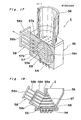
- Figs. 4 to 16 The capsule filling unit is shown particularly in Figs. 4 to 16.
- Fig. 4 illustrates a cap body carrier disc 35 mounted atop a turntable, with accessory components arranged thereabove, but removed for the purpose of clarity
- Fig. 5 illustrates a depending cylinder 36 intermittently rotatable together with the cap body carrier disc 35, a plurality of cup body carrier segments 36 movable incident thereto, and their related mechanisms.
- Fig. 4a which illustrates, on an enlarged scale, a portion encircled by a circle in Fig.
- the cap body carrier disc 35 has a plurality of circumferentially equally spaced groups of cap body receiving pockets 35a defined therein in a predetermined pattern, the number of said pockets 35a in each group being, for example 28, whereas each of the cup body carrier segments has cup body receiving pockets 37a defined therein in the same pattern as that of the pockets 35a in each group, the number of the cup body receiving pockets 37a in each segment 37 being equal to that of the cup body receiving pockets 35a in each group.
- the cup body carrier segments 37 are connected with respective arms 38 in a manner as will be described later and positioned radially outwardly of the depending cylinder 36 while spaced an equal distance from each other in a direction circumferentially of the cylinder 36.
- Each of the arms 38 extends axially slidably through a respective bushing 39, secured to the depending cylinder 36, with its inner end remote from the respective segment 37 carrying a respective cam follower 40.
- All of the cam followers 40 carried by the respective arms 38 and positioned inside the depending cylinder 36 are mounted on and.movably engaged to r a positive motion cam 41 fixedly supported in position inside the depending cylinder 36 in any suitable manner. As will be described later, the positive motion.
- cam 41 is so positioned and so shaped that, during each complete rotation of the cap body carrier disc 35 together with the depending cylinder 36, each of the neighboring cup body carrier segments 37 can be driven to a radially outwardly projected position for the purpose which will become clear from the subsequent description.
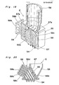
- Fig. 6 illustrates the depending cylinder 36 and a fixed base cylinder 42 positioned coaxially below the depending cylinder 36, both cylinders 36 and 42 being developed in a plane.
- the fixed base cylinder 42 has a generally endless positive motion cam 43 secured to the outer peripheral surface thereof, on which cam 43 are movably mounted cam followers 44 and having a pair of spaced .
- parallel rods 45 extending upwardly therefrom and terminating in rigid connection with the associated cup body carrier segment 37.
- each pair of the parallel rods 45 extend slidably through a respective bracket 47 rigidly mounted on the outer end of the associated arm 38.
- the positive motion cam 43 secured to the base cylinder 42 is so positioned and so shaped as to permit each four cup body carrier segments 37 to be lowered during each complete rotation of the cap body carrier disc 35 and, hence, the depending cylinder 36.
- the cup body carrier segments are not only successively moved in a direction radially outwardly of the depending cylinder 36 from a retracted position to a projected position, but also successively lowered.
- the positive motion cams 41 and 43 are so positioned and so shaped relative to each other that the successive lowering of the cup body carrier segments 37 can take place substantially simultaneously with the successive radially outward movement of the cup body carrier segments 37.
- the cap body carrier disc 35 of the construction described above can, during each complete rotation thereof, be moved past a plurality of work stations, identified by Sl to S12, respectively, at which the following jobs take place.
- Figs. 7 and 8 illustrate the sequence of capsule loading in which each four empty capsules EC which have been successively delivered in the predetermined position, i.e., the cap-topped position, from the delivery drum 25 are transported onto the carrier disc 35
- Fig. 9 illustrates the method of opening each of the capsules E, i.e, the separation of the cap body from the mating cup body in each of the capsules, so transported from the delivery station.
- each of the capsules supplied from the hopper towards the carrier disc 35 is in a prelocked form, i.e, in the form wherein the cup body is temporarily closed by the mating cap body with no powdery or fluid medicine filled therein, which cup body and cap body are respectively identified by Y and X throughout several views of the accompanying drawings in which each capsule is opened with the cap body separated from the cup body.
- the reciprocating transfer unit including the transfer pallet 30 and the slide plate 32 is driven by a drive unit generally -identified by 34 and including a drive cam 34a and a motion translator 34b, the details of which will not be herein described for the sake of brevity.
- the cup body carrier segments 37 which are successively brought into alignment with the capsule loading and separating station Sl during each complete rotation of the depending cylinder 36 are held at the lifted and radially inwardly retracted position as can be seen from Figs. 4 to 6. While the particularly cup body carrier segment 37 is held in the lifted and radially inwardly retracted position with the cup body receiving pockets 37 aligned with one of the groups of the cap body receiving pockets 35a associated therewith, the transfer pallet 30 is brought to the advanced position together with the slide plate 32, as shown in Fig. 9, from the retracted position as shown in Fig. 7.
- the slide plate 32 Shortly before the transfer pallet 30 arrives at the advanced position, the slide plate 32 is held still at the release position so that the capsules EC so transported by the transfer pallet 30 can, simultaneously with the arrival of the pallet 30 at the advanced position, be positively drawn downwards by a suction force, induced in a suction cup 48 positioned beneath the carrier segment 37, into the pockets 35a and 37a then aligned with each other, as / shown in Fig. 9.
- Each of the cap body receiving 'pockets 35a in the cap body carrier disc 35 is in the form of a through-hole of a diameter enough to accommodate the inner diameter of each cap body, but having its lower region constricted radially inwardly to a diameter enough to accommodate the outer diameter of only the cup body.
- each of the cup body receiving pockets 37a in each carrier segment 37 is in.the form of a hole of a diameter enough to accommodate the outer diameter of each cup body, having its bottom perforated at 37b so as to be communicable with the suction cup 48.
- each of the capsules EC when received in the respective cup body receiving pocket 35a is separated into the cap body X, retained in the respective cap body receiving pocket 35a, and the cup body Y retained in the respective cup body receiving pocket 37a as clearly shown in Fig. 9.
- each of the capsules EC is opened in readiness for the filling of a predetermined quantity of, for example, powder as will be be described subsequently.
- This ejecting mechanism 50 comprises a recovery box 51 positioned above the cap body carrier disc 35 and having its bottom perforated at 51a in a pattern identical with the pattern of the cap body receiving pockets 35a in each group and in a size enough to pass the capsules therethrough into the interior of the recovery box 51.
- the mechanism 50 also comprises an ejector plate 52 having knock-out pins 53 equal in number to, and arranged in a pattern identical with, the cap body receiving pockets 35a, and rigidly mounted thereon so as to extend upwardly in alignment with the cap body receiving pockets 35a.
- the ejector plate 52 with the knock-out pins 53 is positioned between the carrier disc 35 and the cup body carrier segment 37 then held in the lowered position, and supported for movement between an inoperative position, as shown in Fig. 10, and a knock-out position, as shown in Fig. 11, in a direction away from and close towards the carrier disc 35, respectively.
- each of the knock-out pins 53 has a diameter smaller than the minimum diameter of each capsule, that is, the outer diameter of the cup body of each capsule, and has a length so selected as to terminate in the vicinity of the opening of each cap body received in the respective cap body receiving pocket 35a, when the ejector plate 52 is driven to the knock-out position as clearly shown in Fig. 11. Accordingly, when the ejector plate 52 is driven from the inoperative position towards the knock-out position, one of the knock-out pins 53 which is aligned with and immediately below the defective capsule ECa knocks the defective capsule ECa out of the associated cap body receiving pocket 35a and upwardly into the box 51 through a corresponding perforation 51a at the bottom of the box 51.
- each of the perforations 51a defined in the bottom of the box 51 is in the form of a slot having its shorter axis slightly smaller than at least the outer diameter of the cap body, and therefore, there is no possibility that the defective capsule ECa once ejected into the box 51 may fall downwards through any one of the perforations 51a, although the defective capsule being ejected may be deformed inwardly as it passes through the perforations 51a into the box 51.
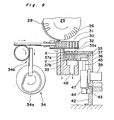
- the cup body carrier segment 37 is held at the lowered and radially outwardly projected position, as shown in Figs. 3 to 6 and 13, in readiness for the filling of different fluid mediums, one medium at each station, into the cup bodies Y retained' in the cup body receiving pockets 37a in each segment 37 then aligned with the stations S4 and S5 one at a time.
- a constant quantity fluid dispensing unit E is disposed and arranged at each of the stations S4 and S5, although in place of the fluid dispenser unit E, any known powder filling mechanism may be employed.
- the illustrated dispenser unit E includes a hopper 56, a valve body 57, a metering unit 58, a valving member 59, and a plurality of dispensing nozzles 54.
- the valving member 59 has a plurality of L-shaped fluid passages 59a defined therein and is rotatable between a receiving position, in which the fluid medium within the hopper 56 flows into the passages 59a, and a dispensing position in which, as shown, the fluid medium within the passages 59a is dispensed through the nozzles 54 into the cup bodies Y carried by the carrier segment 37 and positioned therebelow.
- one of the stations S4 and S5 may be omitted, or the. number of the stations at which the filling is effected may be increased, depending on the number of kinds of the fluid mediums to be filled in the capsules.
- cap bodies which have been separated from the associated cup bodies at the station Sl as shown in Fig. 9 are, after the filling and at the stations S8 and S9, mounted on the associated cup bodies to produce the filled capsules now identified by FC in Fig. 14.
- an arcuate depresser plate 60 is fixedly disposed at the stations S8 and S9 so as to overhang a portion of the outer periphery of the carrier disc 35, at which stations the neighboring carrier segments 37 are brought to the lifted and radially inwardly retracted position as seen from Figs. 2 to6 and 14.
- a lifting plate 61 supported below the segments 37 for movement between lifted and lowered positions in a direction close towards and away from the depresser plate 60, said plate 61 having a plurality of presser rods 62 which are rigidly mounted thereon and arranged in a pattern identical with the pattern of the cap body receiving pockets 35a in each group.
- the lifting plate 61 with the presser rods 62 thereon is essentially similar in structure to the ejector plate 52 with the knock-out pins 53 thereon.
- the capping performed at the station S9 ensures that all of the filled capsules FC are completely closed.
- the filled capsules FC substantially carried by the carrier disc 35 are removed from the carrier disc 35 and from thecapsule filling unit.
- the capsule ejecting unit E is disposed at the station S10, which includes a chute 63 having a plurality of holes 63a defined therein in a pattern identical with that of the cap body receiving pockets 35a in each group, an ejector plate 64 supported below the carrier segment 37, then brought to the station S10 and held in the lifted and radially inwardly retracted position, for movement between inoperative and ejecting positions, and a plurality of ejecting pins 65 rigidly mounted on the ejector plate 64 in alignment with the respective passages 37b communicated with the cup body receiving pockets 37a.
- the chute 63 is-of a generally elongated box-like configuration having its inclined bottom formed at one end with the holes 63a and at the other end with a discharge opening 63b.
- the holes 63a have progressively decreasing depths from the outermost row of the holes 63a which align with the innermost row of- the cap body receiving pockets 35a in each group in the carrier disc, and in correspondence thereto, the ejecting pins 65 have progressively decreasing lengths as shown.
- the group of the cap body receiving pockets 35a and its associated carrier segment 37 are, after the filled capsules FC have been removed therefrom at the ejecting station S10, transferred to the cleaning station Sll at which a suction cup 66 is aligned with such group of the cap body receiving pockets 35a to effect a vacuum cleaning of the pockets 35a and 37a in readiness for the next cycle of empty capsule loading.
- the dispenser unit E comprises a valve assembly 55 including a housing block 57 having a valving member 59, displaceably housed therein, and also-having a pumping unit 58 built-therein.
- a hopper 56 Mounted atop the housing block 55 is a hopper 56 for accommodating a quantity of fluid medium to be filled in each capsule.
- the housing block 57 On one side of the valve assembly 55 opposite to the hopper 56, the housing block 57 has a plurality of injecting nozzles 54 for dispensing quantities of the fluid medium into the cup bodies Y then retained by the particular cup, body carrier segment 37.
- a plunger block 58a Positioned laterally of the valve assembly 55 is a plunger block 58a.
- the valving member 59 is held in a metering position in which a plurality of generally L-shaped passages 59b defined in the valving member 59 communicate respective passages 57a, defined in the housing block 57 in communication with the hopper 56, with passages 57c also defined in the housing block 57 in communication with the pumping unit 58.
- the pumping unit 58 includes plungers 58b equal in number to the passages 57b and axially slidably inserted at one end into these passages 57b and rigidly connected at the other with the plunger block 58a. Therefore, when the valving member 59 is in the metering position shown in Fig. 17, and when the plunger block 58a is displaced in a direction shown by the arrow, the fluid medium within the hopper 56 is sucked and stored in the passages 57b in a predetermined quantity determined by the displacement of the plunger block 58a.
- the valving body 59 having the passages 59b defined therein also has defined therein an equal number of generally L-shaped passages 59c which are, when the valving body 59 is in the metering position as shown in Fig. 17, completely closed by the wall of the housing block 57 around the valving body 59 while containing therein the fluid medium which has been previously supplied.
- the valving body 59 is displaceable in a direction parallel to the-axis of rotation thereof between the metering position shown in Fig. 17 and a dispensing position shown in Fig. 18, over a predetermined distance equal to the sum of the diameter of each of the passages 59b and the space between each neighboring passages. Therefore, when the valving body 59 held in the metering position is displaced to the dispensing position shown in Fig. 18, the passages 59c are brought in position to communicate the passage 57b with the nozzles 54 therethrough while the passages 59b are completely closed by the wall of the housing block 57 around the valving body 59.
- the plunger block 58a When the plunger block 58a is moved in a direction counter to the direction shown by the arrow, i.e., close towards the valve assembly 55 while the valving body 59 is held in the dispensing position, the fluid medium which has been previously primed into the passages 59c can be discharged through the dispensing nozzles 54 in a quantity equal to that injected thereinto from the passages 57b as a result of the displacement of the plunger block 58a.
- the plunger block 58a has a plurality of adjustable positions over the maximum available stroke thereof, in combination with a position adjustment which may be comprised of a positive motion cam mechanism, so that the quantity of the liquid medium dispensed into each capsule can be controlled dependent on the position of the plunger block 58a.
- Figs. 19 and 20 illustrate a modified form of the valve assembly 55.
- the valve assembly 55 employs a generally triangular cross-sectioned valving body 66 having two groups of straight passages defined therein, one group of the passages being identified generally by 66a in Fig. 19 whereas the other group of the passages is identified' generally by 66b in Fig. 20.
- This valving body 66 is displaceable between the metering and dispensing positions in a direction perpendicular to the plane of the drawing of Fig. 19, and when in the metering position as shown in Fig.
- the valving body 66 allows the passages 66a to communicate between ports 67, defined in a bottom wall of the hopper 56 which concurrently forms a part of the housing for the valve assembly 55, and cylinders 58c of a cylinder assembly 58d which concurrently forms another part of the housing for the valve assembly 55 and into which the plungers 58b extend axially slidably.
- the valving body 66 is displaced to the dispensing position as shown in Fig. 20
- the cylinders 58c in the cylinder assembly 58d are communicated with the nozzles 54 through the passages 66b.
- the adjustment of the quantity of the fluid medium to be dispensed into the cup body of each capsule can be achieved in the same way as that described with reference to Figs. 18 and 19.
- valve assembly 55 of the construction shown in and described with reference to Figs. 19 and 20 is-particularly advantageous in that the resistance to the flow of the fluid medium from the hopper 56 to the pumping unit 58 and also from the pumping unit 58 to the nozzles 54 can be minimized because of the employment of the straight passages 66a and 66b.
- valve assembly 55 A further modified form of the valve assembly 55 is shown in Fig. 21, in which only a skeleton of passages is shown for the sake of brevity.
- the valve assembly shown therein comprises a generally rectangular valving body shown by the phantom line 68 and movable between first and second positions in a direction longitudinally thereof.
- the valving body 58 has a group of a plurality of, for example, three, generally -L-shaped passages 69a each having one end communicated through a respective tube 70 with the hopper and the other end adapted to be communicated with a respective cylinder 71 of the pumping unit 58, and another group of L-shaped passages 69b each having one end adapted to be communicated with the respective cylinder 71 and the other end adapted to be communicated through a respective tube 74 with the respective nozzle 54, all of said passages 69a and 69b being defined in the valving body 68 in equally spaced relationship with each other.
- the pumping unit 58 shown therein comprises two separate plunger blocks 72 and 73 each having a plurality of, for example, two plungers 72a or 73a axially slidably inserted into the respective cylinders 71.
- the plunger blocks 72 and 73 are alternately driven so that, when the valving body 68 is in the first position, the fluid medium can be sucked from the hopper through the two passages 69a into the two cylinders 71 associated with the cylinder block 72 and; at the same time, the fluid medium filled in the other two cylinders 71 associated with the plunger block 73 can be purged into the passages 69b and then discharged through the respective nozzles 54.
- each of the nozzles 54 has a discharge port of a diameter so selected as to be smaller than the bore of each tube 74 wherefore any possible change in quantity of the fluid to be dispensed which would occur as a result of leakage of the slurry can be advantageously minimized.
- a powder filling machine comprises a support column 100 supporting a rotary shaft 101 on which a metering disc 103 is mounted for intermittent rotation past a plurality of work stations disposed adjacent the outer periphery of the disc 103.
- work stations include compressing stations Wl, W2 and W3, a metering station W4 and a delivery station W5 which are spaced an equal distance from each other in a direction circumferentially of the metering disc 103.
- Cylindrical hoppers 104, 105, 106 and 107 each having the bottom served by the top surface of the disc 103 are fixedly supported above the disc 103 in alignment with the work stations Wl to W4.
- the hoppers 104 to 107 are of identical construction and, therefore, only one of which, for example, the hopper 104, will be described.
- the hopper 104 (105, 106 or 107) in in the form of a top-closed cylindrical hollow body having a cylindrical side wall 104a (105a, 106a or 107a) having a lower open end provided with a skirt 104b (105b, 106b or 107b), which skirt protrudes downwards therefrom and terminates at a position spaced a predetermined distance, for example, about 0.1 mm, from the top surface of the disc 103.
- the hopper 104 (105, 106 or 107) also has a lid 104c (105c, 106c or 107c) mounted atop the cylindrical side wall 104a (105a, 106a or 107a). It is to be noted that the skirt 107d of the hopper 107 positioned in alignment with the metering station W4 serves as a doctor blade.
- the lid 104c (105c, 106c or 107c) has a bearing hole defined therein coaxially for the support of a stirrer shaft 108 (109, 110 or 111).
- Each of the lids 104c, 105c and 106c of the hoppers 104, 105 and 106 positioned in alignment with the compressing stations Wl to W3 has defined therein a plurality of, for example, 50, holes for the passage therethrough of an equal number of presser rods generally identified by 112, 113 or 114, a port for receiving a powder supply tube 115 and a bearing hole for the support of a respective level sensor 116.
- the central support column 100 supports a plate-like upper transmission box 117 from below, on which box 117 is mounted a master hopper 118 and a powder supply motor 119 for each supply tube 115.
- a gear train including gears 120a, 120b, 120c and 120d is accommodated for controlling the synchronized rotation of the metering disc 103 and the stirrer shafts 108, 109, 110 and 111 in the opposite directions with respect to each other.
- Each of said stirrer shafts 108 to 111 has its lower end to which a stirrer blade assembly 121 is secured.
- each of the powder supply tubes 115 communicated with the respective hoppers 104, 105 and 106, there is disposed a feed screw 122 adapted to be driven by the respective powder supply motor 119 through one or more gears.
- Each of the powder supply motors 119 is controlled in response to an electric signal generated from the associated level sensor 116.
- Each of the powder supply tubes 115 has a branch tube 115a branched from a substantially intermediate portion thereof so as to extend diagonally upwards and communicated with the master hopper 118. At the joint between the two, there is a respective opening 123 defined in a bottom plate 124.
- Each of the openings 123 is adapted to be selectively closed and opened by an annular shutter plate 125 overlapping with the bottom plate 124.
- a shutter lever 126 extending vertically through the transmission box 117, the extent to which the openings 125a defined in the shutter plate 125 overlap with the openings 123 in the bottom plate 124, respectively, can be adjusted between a closed position and fully opened position.
- a rotary stirrer blade assembly 127 rotatable about the disc support shaft 1.01.
- the powder falling downwards by gravity within the master hopper 118 is stirred centripetally and then centrifugally because of the presence of a downwardly .converging baffle 128 integral or rigid with a lower end of the wall of the hopper 118 and conical cap 129 covering the top of the disc support shaft 101, and thereafter falls onto the shutter plate 125.
- the powder so supplied onto shutter plate 125 is then guided towards and distributed into the branch tubes 115a by the motion of the blade assembly 127 without any bridging phenomenon.
- Fixed portions above and below the metering disc 103 support four drive control means for the presser rods 112, 113 and 114 positioned in alignment with the respective stations Wl to W4, and two drive control means 131 for auxiliary presser rods 132 positioned in alignment with the respective stations Wl and W4, respectively.
- the transfer means is comprised of a generally sector-shaped covering 133 of generally U-shaped cross-section opening towards, and substantially closed by, the metering disc 103, which covering 133 extending arcuately between the metering hopper 107 and the distributing hopper 104.
- the blade assembly 121 rotating within the metering hopper 107 brings the powder slag to the entrance leading to the covering 133, the powder slag resting on the metering disc 103 then rotating in one direction shown- by the arrow in Fig. 23, is transported through the covering 133 towards the distributing hopper 104.
- the pellets P contained in respective metering cavities 103a defined in the metering disc 103 are pressed downwards into the respective cup bodies Y, positioned therebelow, by the descending motion of the delivery plungers 134 driven by a delivery plunger drive means 135.
- the capsule cup bodies Y filled with the respective pellets P are subsequently delivered in any known manner to a capping machine by which the capsule cap bodies are mounted to provide the filled capsules.
- a layer of powder identified by Po and deposited on the metering disc 103 is sucked into the metering cavities 103a to fill up the latter at the compressing station Wl.
- the presser rods 112- are driven downwards to ram the masses of the powders within the metering cavities 103a as shown in Fig.
- Ramming of the compressed powder masses P within the cavities 103a is also effected in a similar manner even at each of the compressing stations W2 and W3 by means of the presser rods 113 or 114 as shown in Fig. 24(e).
- a back-up plate 137 is employed to support from below the powder masses P being rammed by the presser rods 113 or 114.
- This back-up plate 137 may be an imperforated integral extensi on of the rod guide 136.
- the auxiliary presser rods 132 are upwardly shifted a predetermined distance to push the pellets P within the metering cavities 103a to such an extent as to allow head portions of the pellets P to be exposed from the metering cavities 103a as shown in Fig. 24(f).
- This predetermined distance over which the auxiliary presser rods 132 at the metering station W4 are upwardly shifted is so selected that that portion of each pellet P which remains within the respective metering cavity 103a corresponds to a predetermined or required amount of the powder to be filled in each capsule.
- the metered pellets P are transferred to the delivery station W5 as a result of the intermittent rotation of the disc 103.
- the delivery plungers 134 are lowered to project into the cavities 103a while pushing the pellets P downwards into the capsule cup bodies Y supported in the respective cup body receiving pockets in the associated carrier segment 37 as shown in Fig. 24(h).
- the powder filling machine of the construction described with reference to an shown in Figs. 22 to 24 employs a metering system wherein the amount of the powder to be filled in each capsule is metered by forming a column of the powder and then scraping an excessive portion of the powder column. Therefore, unlike the conventional metering system utilizing pressure, the quantitative adjustment of the powder and the changeover can readily be performed. Moreover, the adjustment of the compressed masses of powder resulting from the difference in apparent specific gravity of the powder can also be achieved not only during the operation of the machine, but also during the inoperative condition.
Abstract
Description
- The present invention relates to a capsule filing apparatus for filling a filler material such as, for example, powder, slurry or oil paste, into capsules such as hard gelatin capsules.
- The capsules referred to above are generally supplied in a prelocked condition, i.e., a condition in which the capsule cap body is mounted on the capsule cup body, but can readily be removed therefrom at any desired or required time for, for example, filling of the filler material thereinto. Accordingly, in order for the prelocked capsules to be efficiently filled with the material, a series of procedures including, for example, the receipt of each prelocked capsule, the separation of the capsule cap body from its mating capsule cup body, the filling of the material into the capsule cup body, the capping of the filled capsule cup body and the ejection of each filled capsule, must be continuously carried out at respective stations disposed around, for example, a turntable.
- In one prior art filling machine, there is employed a system wherein the capsule cap body and cup body are merely separated from each other in a vertical direction. In another prior art filling machine, there is employed a system wherein the capsule cap body separated from the associated capsule cup body is moved horizontally so that it can wait at a position latterally of the associ- 'ated capsule cup body before the filling of the material into such associated cup body completes. In the first mentioned system, since a sufficient space can be obtained between the separated cap body and cup body, a combination with such a bulky apparatus as a slurry filling mechanism has been impossible. On the other hand, in the last mentioned system, since the direction in which the cap body is moved horizontally must be a centripetal direction, the apparatus tends to be unnecessarily overdimensioned.
- The present invention has been developed with a view to substantially eliminating the above described disadvantages and inconveniences inherent in the prior art apparatuses and has for its essential object to provide a systemized apparatus fabricated in a compact size while incorporating a complicated and bulky slurry filling mechanism and other associated machine units, which apparatus is capable of exhibiting high productivity.
- In order to accomplish the above object, the present invention provides a capsule filling machine comprising a turntable supported for intermittent rotation about a vertical shaft, said turntable when at one work station receiving at least one empty capsule in top-capped posture, said empty capsule comprising an empty cup body having a cap body mounted thereon in telescopic fashion, said turntable being passed during one complete rotation through a plurality of work stations, including said one work station, at which the separation of the cap body from the cup body, the filling of a material into the cup body, the mounting of the cap body on the filled cup body to provide a filled capsule, and the ejection of the filled capsule are successively and sequentially performed, said empty capsule and said cap body, separated from the apsoci, ated cup body, being conveyed along a horizontal circumferential path whereas the cup body in a region of separation is conveyed along a modified path including a side way extending outwardly and downwardly with respect to the horizontal circumferential path.
- In the machine of the above described construction according to the present invention, a plurality of groups of a plurality of the capsules are substantially subjected to the operations, respectively.
- During the intermittent rotation of the turntable, the cap body is transported along the horizontal circumferential path while received in a cap body receiving pocket defined in a cap body carrier disc mounted atop the turntable. On the other hand, the cup body is transported while received in a cup body receiving pocket defined in a cup body carrier segment movable along the modified path.
- Moreover, according to the present invention, the cup body carrier segment is employed in a plural number, and is mounted on a respective rod, said respective rod being supported by a bracket for movement up and down, said bracket being mounted on a respective arm which extends radially outwardly from a cam follower engaged in a positive motion cam arranged in a fixed member below the cap body carrier disc, the arms for each cup body carrier segment being movable in synchronism with the cap body carrier disc and telescopically movable in a direction radially outwardly in dependence on the position of the cap body carrier disc. The rod has a cam follower engaged in a positive motion cam provided in a fixed member of the bottom of the turntable, and is downwardly biased by a spring relative to the bracket and is moved up and down in dependence on the work stations.
- Therefore, as the turntable rotates, the cup body carrier segment is displaced first in a direction downwardly of the axis of rotation of the turntable and then in a direction radially outwardly thereof during the passage thereof through particular work stations and, after the passage therethrough along an arcuate path outwardly of the cap body carrier disc, said segment is radially inwardly shifted while upwardly shifted to return to the circumferen- . tial path.
- In this construction, the defective capsule in which the cap body and the cup body are not separated from each other is removed at one of the work stations at which the cup body carrier segment is downwardly shifted, On the other hand, the filling of the material into the cup body is carried out at one of the work stations where the arcuate path is situated, and the capping after the filling is carried out at one of the work positions where the cup body carrier segment displaces from the arcuate path to the circumferential path.
- This and other objects and features of the present invention will become clear from the following description taken in conjunction with a preferred embodiment with reference to the accompanying drawings, in which:
- Figs. 1 and 2 are schematic side and top views of a capsule filling machine according to the present invention, respectively;
- Fig. 3 is a schematic side sectional view, on an enlarged scale, of a capsule rectifying unit used in the machine;
- Fig. 4 is a top plan view of a portion of the machine showing a cap body carrier disc;
- Fig. 5 is a top plan view of a portion of the machine with the cap body carrier disc removed to show an arrangement of cup body carrier segments;
- Fig. 6 is a side view of a depending cylinder developed into a plane representation;
- Figs. 7 to 9 are schematic side sectional views, respectively, showing the sequence of delivery of the rectified capsules from the rectifying unit onto the cap body carrier disc and the subsequent separation of the cap body from the cup body of each capsule;
- Fig. 10 is a view similar to Fig. 7, showing a defective capsule rejecting unit;
- Fig. 11 is a side sectional view of a defective capsule recovery box, showing the method in which the defective capsule is ejected into the box;
- Fig. 12 is a top plan view of a portion of the recovery box;
- Fig. 13 is a view similar to Fig. 7, showing a constant quality fluid dispensing unit;
- Fig. 14 is a view similar to Fig. 7, showing a capping unit;
- Fig. 15 is a view similar to Fig. 7, showing an ejecting unit for collecting the filled capsules;
- Fig. 16 is a view similar to Fig. 7, showing a cleaning unit;
- Fig. 17 is a perspective view, with a portion cut away, showing a constant quality fluid dispensing unit in one operative position;
- Fig. 18 is a view similar to Fig. 17, showing the dispensing unit in another operative position;
- Figs. 19 and 20 are sectional views of a modified form of the dispensing unit in different operative positions, respectively;
- Fig. 21 is a skeleton diagram showing a further modified form of the dispensing unit;
- Fig. 22 is a side view, with a portion shown in section, of a powder filling machine according to the present invention;
- Fig. 23 is a top plan view, on an enlarged scale and with a portion cut away, of a portion of the powder filling machine; and
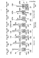
- Figs. 24(a) to 24(h) are schematic diagrams showing the sequence of powder filling performed by the powder filling machine.
- Before the description of the present invention proceeds, it is to be noted that like parts are designated by like reference numerals throughout the accompanying drawings.
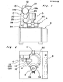
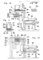
- Referring first to Figs. 1 and 2 showing a capsule filling system in schematic representation, the capsule filling machine shown therein comprises a filling unit A, a gauge and control panel B therefor, a capsule rectifying unit C, a constant quantity dispensing unit D, and a capsule ejecting unit E. These units A to E are operatively associated and synchronized so as to achieve a sequence of intended functions in cooperation with their related components not shown in Figs. 1 and 2. These units A to E will now be described individually in detail.
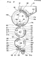
- Referring to Fig. 3, the capsule rectifying unit shown therein in schematic side sectional representation comprises a
hopper 10, asupply drum 15 supported for rotation in one direction generally below thehopper 10 with an outer peripheral portion thereof protruding into thehopper 10, a rectifyingdrum 20 supported immediately below thesupply drum 15 for rotation in a direction counter to the direction of rotation of thesupply drum 15, and adelivery drum 25 supported immediately below the rectifyingdrum 20 for rotation in a direction counter to the direction of rotation of the rectifyingdrum 20. Thesedrums supply drum 15 is aroll brush 12 operable to facilitate the random insertion of some of empty capsules EC, accommodated randomly within thehopper 10, intopockets 16 defined in the outer peripheral surface of thesupply drum 15 as will be described subsequently. - Although only some of the
pockets 16 are shown in Fig. 3, thepockets 16 are distributed in at least one circumferentially extending row all over the outer peripheral surface of thesupply drum 15 in equally spaced relation to each other and so formed in thesupply drum 15 as to extend in a direction radially of thedrum 15. Each of thepockets 16 has a minimum diameter enough to accommodate therein a cap body of each empty capsule EC, that is, slightly greater than the outer diameter of the cap body of each empty capsule EC, a portion of the opening of eachpocket 16 being substantially flared outwardly in a direction conforming to the direction of rotation of thesupply drum 15. Specifically, each of thepockets 16 is so shaped and so sized that, as some of thepockets 16 successively move through thehopper 10 during each complete rotation of thesupply drum 15, some of the empty capsules EC within thehopper 10 can be randomly received into the associatedpockets 16 regardless of the posture of each empty capsule EC. It is. to be noted that, for the purpose of description of the present invention, the posture wherein each capsule is received within the respective pocket or a similar receptacle with the associated cap body oriented towards the bottom of such pocket or receptacle will be referred to as "bottom-capped position" whereas that with the associated cap body oriented towards the top of such pocket or receptacle will be referred to as "top-capped position". Theroll brush 12 serves to sweep some of the empty capsules EC, resting on the outer peripheral surface of thedrum 15 without being received in anypockets 16, off from thedrum 15 into thehopper 10. - Each of the
pockets 16 has apassage 16a defined in thedrum 15 in communication with therespective pocket 16. All of thepassages 16a are arranged in a circle concentric with the axis of rotation of thedrum 15, and some of them are adapted to be successively communicated with a source of vacuum through avacuum shoe 17a which extends so as to follow the curvature of the circle of thepassages 16a for evacuating some of the pockets -16 then passing through the interior of thehopper 10. During the rotation of thedrum 10; thepassages 16a can also be successively communicated with a source of compressed air through ablow shoe 18, defined in register with a first meeting point where the supply and rectifyingdrums vacuum shoe 17b defined next to theblow shoe 18 on the leading side with respect to the direction of rotation of thedrum 15. - Thus, it will readily be seen that, during each complete rotation of the
supply drum 15, some of the empty capsules EC within thehopper 10 can be sucked into therespective pockets 16 then communicated with the vacuum source through the associatedpassage 16a and thevacuum shoe 17a and are transported towards the first meeting point. At the first meeting point, thepockets 16 are successively communicated with the compressed air source one at a time through the associatedpassages 16a and theblow shoe 18 for the transfer of the empty capsule EC from thesupply drum 15 onto the rectifyingdrum 20 as will be described subsequently. As will become clear from the subsequent description, some of the empty capsules EC which are not successively transferred onto the rectifyingdrum 20 are again sucked into and retained in therespective pockets 16 upon the subsequent communication of theassociated passages 16a with the vacuum source through thevacuum shoe 17b, and are transferred onto the rectifyingdrum 20 at the first meeting point during the next cycle of rotation of thesupply drum 15. This design makes it possible to minimize any possible failure in capsule supply. - Positioned radially outwardly of the lower half of the
supply drum 15 and extending from a position adjacent the first meeting point in opposite directions away from each other so as to follow the curvature of the outer periphery of thedrum 15 is trailing and leadingguard plates pockets 16 during the transportation thereof by thesupply drum 15. It is to be noted that the number of thepockets 16 in thesupply drum 15 is, for example, 36, although it may not be always limited thereto and may be any desired number. - The rectifying
drum 20 is operable to transport the empty capsules EC, received successively from thesupply drum 15 at the first meeting point, towards the second meeting point where the outer peripheral surface of the rectifyingdrum 20 is spaced the minimum possible, distance from that of thedelivery drum 25 positioned immediately therebelow, while allowing the empty capsules EC, being transported thereby, to be rectified in a definite position required for all of the empty capsules to be received by thedelivery drum 25 in bottom-capped posture or position. As shown, the rectifyingdrum 20 has its outer peripheral surface formed with at least one circumferential row of a plurality of, for example, three, groups of four equally spacedpockets 21 each group defined therein so as to extend generally radially inwardly thereof, the three groups of thepockets 21 being spaced an equal distance from each other in a direction circumferentially of thedrum 20 while leaving an equal number of smooth surface regions each between the neighboring groups of thepockets 21. - Each of the
pockets 21 in the rectifyingdrum 20 comprises a radial pocket portion 21a of a diameter enough to accommodate therein only the cup body of each capsule EC, i.e., slightly greater than the outer diameter of the cup body of each capsule, but smaller than the outer diameter of the cap body of each capsule, and a transverse pocket portion 21b extending in a trailing direction circumferentially of thedrum 20 and having a leading end communicated with and continued to the respective radial pocket portion 21a, the length of said transverse pocket portion 21b corresponding to the length of each empty capsule EC. The rectifyingdrum 20 also has passages 21c equal in number to the total number of thepockets 21, defined therein in communication with the respective radial pocket portions 21a and arranged in a circle concentric with the axis of rotation of the rectifyingdrum 20. - As is "the case with the
pockets 16 in thesupply drum 15, all of thepockets 21 in the rectifyingdrum 20 can be successively communicated with the vacuum source through avacuum shoe 22, which extend angularly through a predetermined angle from a position in register with the first meeting point in a direction conforming to the direction of rotation of thedrum 20, and then with the compressed air source through ablow shoe 23 positioned at a location in register with the second meeting point. More specifically, during each complete rotation of the rectifyingdrum 20, all of the groups of thepockets 21 are successively brought to the first meeting point at which the empty capsules EC successively blown off from thepockets 16 in thesupply drum 15 are received in thepockets 21 in the rectifyingdrum 20 and then transported towards the second meeting point at which they are successively transferred from the rectifyingdrum 20 onto thedelivery drum 25. - As hereinbefore described in connection with the
supply drum 15, all of the empty capsules EC received in thepockets 16 are not always held in the definite position, and some are held in the top-capped position and some are in the bottom-capped position. Accordingly, while each empty capsule transported by thesupply drum 15 while received in the associatedpocket 16 in the bottom-capped position is, when transferred onto the rectifyingdrum 20 at the first meeting point, received in the associatedpocket 21 with its cup body sucked into and retained in the respective radial pocket portion 21a, each empty capsule transported by thesupply drum 15 while received in the associatedpocket 16 in the top-capped position is at the first meeting point received in the associatedpocket 21 with its cap body closing the opening of the respective radial pocket portion 21a and with its cup body partially protruding radially outwardly from the outer periphery of the rectifyingdrum 20. - All of the empty capsules EC which are being transported from the first meeting point towards the second meeting point by the rectifying
drum 20 while received in therespective pockets 21 in the bottom-capped position with their cup bodies protruding radially outwardly from the outer periphery of thedrum 20 can be successively laid down to lie within the respective transverse pocket portions 21b by the action of a rectifyingplate 24. Thisplate 24 is positioned radially outwardly of the outer periphery of thedrum 20, extending from a position in register with the leading end of thevacuum shoe 22 arcuately down to a position preceding to and in the close vicinity of the second meeting point. The rectifyingplate 24 concurrently serves as a guard plate similar to theguard plate 19a associated with thesupply drum 15, but has its trailing end remote from the second meeting point engageable with the radially outwardly protruding cup body of each empty capsule, that is received in thepockets 21 in the bottom-capped position, to lay it down. It is to be noted that the trailing end of the rectifyingplate 24 is so positioned relative to the leading end of thevacuum shoe 22 that the trailing end of the rectifyingplate 24 can engage the radially outwardly protruding cup body of the empty capsule EC substantially simultaneously with the incommunication of thepocket 21, receiving such empty capsule EC, from the vacuum source. - The
delivery drum 25 positioned immediately below the rectifyingdrum 20 is operable to transport the empty capsules EC, transferred successively from the rectifyingdrum 20 at the second meeting position, towards a delivery station defined immediately below thedelivery drum 25. Thisdrum 25 is of a construction identical with the rectifyingdrum 20 except that all groups of the four pockets in each group, identified generally by 26, are identical in shape and size with thepockets 16 in thesupply drum 15. Thepockets 26 of all groups can, during each complete rotation of thedelivery drum 25, be communicated with the vacuum source through their associatedpassages 26a and avacuum shoe 27, extending a predetermined angle from a position in register with the second meeting point to a position in register with a trailing end of aguard plate 29, for receiving and retaining the empty capsules EC within therespective pockets 26, and then with the compressed air source through their associatedpassages 26a and a blow shoe .28 positioned in register with the delivery station. It is, however, to be noted that, unlike eachpocket 16 in thesupply drum 15, eachpocket 26 in thedelivery drum 25 has a portion of the opening thereof flared generally radially outwardly in a direction counter to the direction of rotation of thedrum 25 and in opposite relation to that of thepocket 16 in thesupply drum 15. - Referring to the rectifying
drum 20, each empty capsule received in therespective pocket 21 in the bottom-capped position, i.e., with its cap body protruding radially outwardly from the outer periphery of thedrum 20 can be laid down in contact with the trailing end of the rectifyingplate 24 so as to lie within the associated transverse pocket portion 21b, as hereinbefore described. At this time, the empty capsule received in thepocket 21 in the bottom-capped position is laid down in a trailing direction with respect to the direction of rotation of thedrum 20, and the cap body of the laid-down empty capsule conforms to the direction of rotation of thedrum 20 without being received in the radial pocket portion 21a of thatpocket 21 by the reason which has been previously described. On the other hand, since thedelivery drum 25 is driven in a direction counter to the direction of rotation of the rectifyingdrum 20 and since that portion of the opening of eachpocket 26 in thedelivery drum 25 is generally radially outwardly flared in the direction counter to the direction of rotation of thedrum 25, all of the laid-down empty capsules transported by the rectifyingdrum 20 can, as they are successively brought to the second meeting point, be blow off from therespective pockets 16 into the mating pockets 26 in thedelivery drum 25 with their cap bodies oriented radially inwardly of thedrum 25, having been reversed in position. - As regards the empty capsules transported by the rectifying
drum 20 while received in therespective pockets 21 in the top-capped position, these top-capped empty capsules can, as they are brought to the second meeting point, be blown off from thepockets 21 straightforwards into the mating pockets 26 in thedrum 25 without having been reversed in position because each top-capped empty capsule in therespective pocket 21 is at the second meeting point brought in line with the longitudinal axis of the associatedpocket 26 in thedrum 25 then aligned therewith. - The
guard plate 29 extending from the position in register with the leading end of thevacuum shoe 27 to the position in the close vicinity of the delivery station while following the curvature of the outer periphery of thedrum 25 serves to avoid any possible separation and fall of the capsule EC being transported by thedelivery drum 25 towards the delivery station. - Positioned immediately below the
delivery drum 25 is a reciprocating transfer unit including a transfer pallet -30 supported for linear movement between advanced and retracted positions, shown by the phantom line and the solid line, respectively, past the delivery station-in a direction tangential to the outer periphery of thedelivery drum 25. Thisreciprocating transfer pallet 30 has a row of cylindricalbottomless pockets 31 each extending completely through the thickness thereof and having a depth greater than the length of each capped capsule EC; said row of thebottomless pockets 31 extending in a direction conforming to the direction of movement of thetransfer pallet 30. The transfer unit also includes aslide plate 32 slidable underneath the transfer unit between a support position in which the bottoms of therespective pockets 31 in thetransfer pallet 30 are partially closed thereby, and a release position in which they are completely opened, and avacuum cup 33 positioned immediately below theslide plate 32 in alignment with the delivery station. - From the retracted position shown by the solid line towards the advanced position shown by the phantom line, the
transfer pallet 30 is driven at such a speed that all of thepockets 31 in thetransfer pallet 30 can be successively brought into alignment with thepockets 26 of each group in thedelivery drum 25 at the delivery station for receiving the respective empty capsules EC then blown off from thedelivery drum 25. Theslide plate 32 is at this time held at the support position, shown by the solid line, to prevent each of the capsules, then successively received from thedelivery drum 25 into therespective pockets 31 in thetransfer unit 30 at the delivery station, from being sucked into thesuction cup 33 having passed through therespective pocket 31. During the movement of thetransfer pallet 30 from the retracted position to the advanced position, theslide plate 32 moves together with thetransfer pallet 30 from the support position to the release position which is aligned with the advanced position of thetransfer pallet 30. However, as soon as theslide plate 32 arrives at the release position, theslide plate 32 starts its return movement back toward the support position relative to thetransfer pallet 30 which starts its return movement back to the retracted position after the return of theslide plate 32. Therefore, at the advanced position of the transfer pallet. 30, the capsules EC received in therespective pockets 31 are, as theslide plate 32 returns towards the support position, allowed to fall, or otherwise be sucked, into a receiving component of the capsule filling unit A which will be described later. - The capsule filling unit is shown particularly in Figs. 4 to 16. Referring first to Figs. 4 to 6 in which the capsule filling unit is outlined, Fig. 4 illustrates a cap
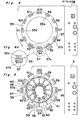
body carrier disc 35 mounted atop a turntable, with accessory components arranged thereabove, but removed for the purpose of clarity, and Fig. 5 illustrates a dependingcylinder 36 intermittently rotatable together with the capbody carrier disc 35, a plurality of cupbody carrier segments 36 movable incident thereto, and their related mechanisms. As best shown in Fig. 4a which illustrates, on an enlarged scale, a portion encircled by a circle in Fig. 4, the capbody carrier disc 35 has a plurality of circumferentially equally spaced groups of capbody receiving pockets 35a defined therein in a predetermined pattern, the number of saidpockets 35a in each group being, for example 28, whereas each of the cup body carrier segments has cupbody receiving pockets 37a defined therein in the same pattern as that of thepockets 35a in each group, the number of the cupbody receiving pockets 37a in eachsegment 37 being equal to that of the cupbody receiving pockets 35a in each group. - The cup
body carrier segments 37 are connected withrespective arms 38 in a manner as will be described later and positioned radially outwardly of the dependingcylinder 36 while spaced an equal distance from each other in a direction circumferentially of thecylinder 36. Each of thearms 38 extends axially slidably through arespective bushing 39, secured to the dependingcylinder 36, with its inner end remote from therespective segment 37 carrying arespective cam follower 40. All of thecam followers 40 carried by therespective arms 38 and positioned inside the dependingcylinder 36 are mounted on and.movably engaged to r apositive motion cam 41 fixedly supported in position inside the dependingcylinder 36 in any suitable manner. As will be described later, the positive motion.cam 41 is so positioned and so shaped that, during each complete rotation of the capbody carrier disc 35 together with the dependingcylinder 36, each of the neighboring cupbody carrier segments 37 can be driven to a radially outwardly projected position for the purpose which will become clear from the subsequent description. - Fig. 6 illustrates the depending
cylinder 36 and a fixedbase cylinder 42 positioned coaxially below the dependingcylinder 36, bothcylinders base cylinder 42 has a generally endlesspositive motion cam 43 secured to the outer peripheral surface thereof, on whichcam 43 are movably mountedcam followers 44 and having a pair of spaced .parallel rods 45 extending upwardly therefrom and terminating in rigid connection with the associated cupbody carrier segment 37. As shown, each pair of theparallel rods 45 extend slidably through arespective bracket 47 rigidly mounted on the outer end of the associatedarm 38. Thepositive motion cam 43 secured to thebase cylinder 42 is so positioned and so shaped as to permit each four cupbody carrier segments 37 to be lowered during each complete rotation of the capbody carrier disc 35 and, hence, the dependingcylinder 36. - Thus, it is clear that, during each rotation of the cap
body carrier disc 35 in one direction shown by the arrow in Fig. 4, the cup body carrier segments are not only successively moved in a direction radially outwardly of the dependingcylinder 36 from a retracted position to a projected position, but also successively lowered. As will be described later, thepositive motion cams body carrier segments 37 can take place substantially simultaneously with the successive radially outward movement of the cupbody carrier segments 37. It is, however, to be noted that, although some of thecam followers 44 engaged in thecam 43 are disengaged from thecam 43 during a period in which the associated cup body carrier segments are radially outwardly moved to the projected position, therods 45 are downwardly biased as hereinbefore described and, theretore, the respective cup body carrier segment is maintained at a lowered position. - The cap
body carrier disc 35 of the construction described above can, during each complete rotation thereof, be moved past a plurality of work stations, identified by Sl to S12, respectively, at which the following jobs take place.
- Figs. 7 and 8 illustrate the sequence of capsule loading in which each four empty capsules EC which have been successively delivered in the predetermined position, i.e., the cap-topped position, from the
delivery drum 25 are transported onto thecarrier disc 35, and Fig. 9 illustrates the method of opening each of the capsules E, i.e, the separation of the cap body from the mating cup body in each of the capsules, so transported from the delivery station. - It is to be noted that each of the capsules supplied from the hopper towards the
carrier disc 35 is in a prelocked form, i.e, in the form wherein the cup body is temporarily closed by the mating cap body with no powdery or fluid medicine filled therein, which cup body and cap body are respectively identified by Y and X throughout several views of the accompanying drawings in which each capsule is opened with the cap body separated from the cup body. It is also to be noted that the reciprocating transfer unit including thetransfer pallet 30 and theslide plate 32 is driven by a drive unit generally -identified by 34 and including adrive cam 34a and amotion translator 34b, the details of which will not be herein described for the sake of brevity. - Referring to Figs. 7 to 9, the cup
body carrier segments 37 which are successively brought into alignment with the capsule loading and separating station Sl during each complete rotation of the dependingcylinder 36 are held at the lifted and radially inwardly retracted position as can be seen from Figs. 4 to 6. While the particularly cupbody carrier segment 37 is held in the lifted and radially inwardly retracted position with the cup body receiving pockets 37 aligned with one of the groups of the capbody receiving pockets 35a associated therewith, thetransfer pallet 30 is brought to the advanced position together with theslide plate 32, as shown in Fig. 9, from the retracted position as shown in Fig. 7. Shortly before thetransfer pallet 30 arrives at the advanced position, theslide plate 32 is held still at the release position so that the capsules EC so transported by thetransfer pallet 30 can, simultaneously with the arrival of thepallet 30 at the advanced position, be positively drawn downwards by a suction force, induced in asuction cup 48 positioned beneath thecarrier segment 37, into thepockets - Each of the cap body receiving '
pockets 35a in the capbody carrier disc 35 is in the form of a through-hole of a diameter enough to accommodate the inner diameter of each cap body, but having its lower region constricted radially inwardly to a diameter enough to accommodate the outer diameter of only the cup body. On the other hand, each of the cupbody receiving pockets 37a in eachcarrier segment 37 is in.the form of a hole of a diameter enough to accommodate the outer diameter of each cup body, having its bottom perforated at 37b so as to be communicable with thesuction cup 48. Therefore, it will readily be seen that each of the capsules EC when received in the respective cupbody receiving pocket 35a is separated into the cap body X, retained in the respective capbody receiving pocket 35a, and the cup body Y retained in the respective cupbody receiving pocket 37a as clearly shown in Fig. 9. In this way, each of the capsules EC is opened in readiness for the filling of a predetermined quantity of, for example, powder as will be be described subsequently. - When the group of the cap
body receiving pockets 35a and its associated cupbody carrier segment 37 are brought to the work station S3 incident to the intermittent rotation of the dependingcylinder 36, the cupbody carrier segment 37 is brought to a lowered position while having been radially outwardly moved a certain distance as shown in Figs. 4 to 6 and 10. The job performed at this station S3 will not be worked out, if all of the capsules have been completely opened. However, assuming that one of the capsules fails to be opened, that is, assuming that the cap body and the cup body of one of the capsules are not separated from each other, at the station Sl and, therefore, the cup body of such one of the capsules remains suspended from the associated cap body retained in the capbody receiving pocket 35a as shown in Fig. 10, this defective capsule, now identified by ECa in Figs. 10 and 11, can be removed from thecarrier disc 35 in the manner which will now be described with particular reference to Figs. 10 to 12. - At the station S3, there is disposed an ejecting mechanism generally identified by 50. This
ejecting mechanism 50 comprises arecovery box 51 positioned above the capbody carrier disc 35 and having its bottom perforated at 51a in a pattern identical with the pattern of the capbody receiving pockets 35a in each group and in a size enough to pass the capsules therethrough into the interior of therecovery box 51. Themechanism 50 also comprises anejector plate 52 having knock-outpins 53 equal in number to, and arranged in a pattern identical with, the capbody receiving pockets 35a, and rigidly mounted thereon so as to extend upwardly in alignment with the capbody receiving pockets 35a. Theejector plate 52 with the knock-outpins 53 is positioned between thecarrier disc 35 and the cupbody carrier segment 37 then held in the lowered position, and supported for movement between an inoperative position, as shown in Fig. 10, and a knock-out position, as shown in Fig. 11, in a direction away from and close towards thecarrier disc 35, respectively. - It is to be noted that each of the knock-out
pins 53 has a diameter smaller than the minimum diameter of each capsule, that is, the outer diameter of the cup body of each capsule, and has a length so selected as to terminate in the vicinity of the opening of each cap body received in the respective capbody receiving pocket 35a, when theejector plate 52 is driven to the knock-out position as clearly shown in Fig. 11. Accordingly, when theejector plate 52 is driven from the inoperative position towards the knock-out position, one of the knock-outpins 53 which is aligned with and immediately below the defective capsule ECa knocks the defective capsule ECa out of the associated capbody receiving pocket 35a and upwardly into thebox 51 through a corresponding perforation 51a at the bottom of thebox 51. - As best shown in Fig. 12, each of the perforations 51a defined in the bottom of the
box 51 is in the form of a slot having its shorter axis slightly smaller than at least the outer diameter of the cap body, and therefore, there is no possibility that the defective capsule ECa once ejected into thebox 51 may fall downwards through any one of the perforations 51a, although the defective capsule being ejected may be deformed inwardly as it passes through the perforations 51a into thebox 51. - At the stations S4 and S5, the cup
body carrier segment 37 is held at the lowered and radially outwardly projected position, as shown in Figs. 3 to 6 and 13, in readiness for the filling of different fluid mediums, one medium at each station, into the cup bodies Y retained' in the cupbody receiving pockets 37a in eachsegment 37 then aligned with the stations S4 and S5 one at a time. For this purpose, as shown in Fig. 13, a constant quantity fluid dispensing unit E is disposed and arranged at each of the stations S4 and S5, although in place of the fluid dispenser unit E, any known powder filling mechanism may be employed. - Referring to Fig. 13, the illustrated dispenser unit E includes a
hopper 56, avalve body 57, ametering unit 58, avalving member 59, and a plurality of dispensingnozzles 54.' The valvingmember 59 has a plurality of L-shapedfluid passages 59a defined therein and is rotatable between a receiving position, in which the fluid medium within thehopper 56 flows into thepassages 59a, and a dispensing position in which, as shown, the fluid medium within thepassages 59a is dispensed through thenozzles 54 into the cup bodies Y carried by thecarrier segment 37 and positioned therebelow. - It is to be noted that, if desired, one of the stations S4 and S5 may be omitted, or the. number of the stations at which the filling is effected may be increased, depending on the number of kinds of the fluid mediums to be filled in the capsules.
- The cap bodies which have been separated from the associated cup bodies at the station Sl as shown in Fig. 9 are, after the filling and at the stations S8 and S9, mounted on the associated cup bodies to produce the filled capsules now identified by FC in Fig. 14.
- For this purpose, as shown in Figs. 2 and 14, an
arcuate depresser plate 60 is fixedly disposed at the stations S8 and S9 so as to overhang a portion of the outer periphery of thecarrier disc 35, at which stations the neighboringcarrier segments 37 are brought to the lifted and radially inwardly retracted position as seen from Figs. 2 to6 and 14. Cooperable with thedepresser plate 60 is a liftingplate 61 supported below thesegments 37 for movement between lifted and lowered positions in a direction close towards and away from thedepresser plate 60, saidplate 61 having a plurality ofpresser rods 62 which are rigidly mounted thereon and arranged in a pattern identical with the pattern of the capbody receiving pockets 35a in each group. The liftingplate 61 with thepresser rods 62 thereon is essentially similar in structure to theejector plate 52 with the knock-outpins 53 thereon. - Thus, it will readily be seen that, when the lifting
plate 61 is moved from the lowered position, shown by the phantom line, towards the lifted position shown by the solid line, thepresser rods 62 pass through thepassages 37b and then lift from below the cup bodies Y which have been retained in the cupbody receiving pockets 37a in each of thecarrier segments 37 and have been filled with the fluid medium such as, for example, oil paste or slurry. As the liftingplate 61 is further moved towards the lifted position, the filled cup bodies Y are lifted and subsequently received in the associated cap bodies X, then received in the capbody receiving pockets 35a, while the latter are retained in position by thedepresser plate 60 positioned immediately thereabove. When the cap bodies X are mounted on the associated cup bodies Y, the capsules are completely closed or locked, in contrast to the prelocked condition in which each cap body can be readily removed from the respective cup body. - While only the station S8 may be enough for the capping procedure, the capping performed at the station S9 ensures that all of the filled capsules FC are completely closed.
- At the subsequent station S10, the filled capsules FC substantially carried by the
carrier disc 35 are removed from thecarrier disc 35 and from thecapsule filling unit. - Referring to Fig. 15, the capsule ejecting unit E is disposed at the station S10, which includes a
chute 63 having a plurality ofholes 63a defined therein in a pattern identical with that of the capbody receiving pockets 35a in each group, anejector plate 64 supported below thecarrier segment 37, then brought to the station S10 and held in the lifted and radially inwardly retracted position, for movement between inoperative and ejecting positions, and a plurality of ejectingpins 65 rigidly mounted on theejector plate 64 in alignment with therespective passages 37b communicated with the cupbody receiving pockets 37a. - The
chute 63 is-of a generally elongated box-like configuration having its inclined bottom formed at one end with theholes 63a and at the other end with adischarge opening 63b. In view of the bottom of thechute 63 inclined relative to thecarrier disc 35, theholes 63a have progressively decreasing depths from the outermost row of theholes 63a which align with the innermost row of- the capbody receiving pockets 35a in each group in the carrier disc, and in correspondence thereto, the ejecting pins 65 have progressively decreasing lengths as shown. - Thus, it is clear that, when the
ejector plate 64 is moved from the lowermost position to the lifted position by a suitable drive (not shown), the filled capsules FC retained in the capbody receiving pockets 35a in each group are popped up by the ejecting pins 65 into the interior of thechute 63, which subsequently fall by gravity towards thedischarge opening 63b along the inclined bottom. The filled capsules FC discharged from thedischarge opening 63b may be conveyed to a packaging machine. - The group of the cap
body receiving pockets 35a and its associatedcarrier segment 37 are, after the filled capsules FC have been removed therefrom at the ejecting station S10, transferred to the cleaning station Sll at which asuction cup 66 is aligned with such group of the capbody receiving pockets 35a to effect a vacuum cleaning of thepockets - The details of the fluid dispenser unit E are illustrated in Figs. 17 and 18. The dispenser unit E comprises a
valve assembly 55 including ahousing block 57 having a valvingmember 59, displaceably housed therein, and also-having apumping unit 58 built-therein. Mounted atop thehousing block 55 is ahopper 56 for accommodating a quantity of fluid medium to be filled in each capsule. On one side of thevalve assembly 55 opposite to thehopper 56, thehousing block 57 has a plurality of injectingnozzles 54 for dispensing quantities of the fluid medium into the cup bodies Y then retained by the particular cup,body carrier segment 37. Positioned laterally of thevalve assembly 55 is aplunger block 58a. - In the illustrated condition of Fig. 17, the valving
member 59 is held in a metering position in which a plurality of generally L-shapedpassages 59b defined in thevalving member 59 communicaterespective passages 57a, defined in thehousing block 57 in communication with thehopper 56, with passages 57c also defined in thehousing block 57 in communication with thepumping unit 58. Thepumping unit 58 includesplungers 58b equal in number to thepassages 57b and axially slidably inserted at one end into thesepassages 57b and rigidly connected at the other with theplunger block 58a. Therefore, when thevalving member 59 is in the metering position shown in Fig. 17, and when theplunger block 58a is displaced in a direction shown by the arrow, the fluid medium within thehopper 56 is sucked and stored in thepassages 57b in a predetermined quantity determined by the displacement of theplunger block 58a. - It is to be noted that the
valving body 59 having thepassages 59b defined therein also has defined therein an equal number of generally L-shapedpassages 59c which are, when thevalving body 59 is in the metering position as shown in Fig. 17, completely closed by the wall of thehousing block 57 around thevalving body 59 while containing therein the fluid medium which has been previously supplied. - The
valving body 59 is displaceable in a direction parallel to the-axis of rotation thereof between the metering position shown in Fig. 17 and a dispensing position shown in Fig. 18, over a predetermined distance equal to the sum of the diameter of each of thepassages 59b and the space between each neighboring passages. Therefore, when thevalving body 59 held in the metering position is displaced to the dispensing position shown in Fig. 18, thepassages 59c are brought in position to communicate thepassage 57b with thenozzles 54 therethrough while thepassages 59b are completely closed by the wall of thehousing block 57 around thevalving body 59. - When the
plunger block 58a is moved in a direction counter to the direction shown by the arrow, i.e., close towards thevalve assembly 55 while thevalving body 59 is held in the dispensing position, the fluid medium which has been previously primed into thepassages 59c can be discharged through the dispensingnozzles 54 in a quantity equal to that injected thereinto from thepassages 57b as a result of the displacement of theplunger block 58a. - Preferably, the
plunger block 58a has a plurality of adjustable positions over the maximum available stroke thereof, in combination with a position adjustment which may be comprised of a positive motion cam mechanism, so that the quantity of the liquid medium dispensed into each capsule can be controlled dependent on the position of theplunger block 58a. - Figs. 19 and 20. illustrate a modified form of the
valve assembly 55. In this modification, thevalve assembly 55 employs a generally triangularcross-sectioned valving body 66 having two groups of straight passages defined therein, one group of the passages being identified generally by 66a in Fig. 19 whereas the other group of the passages is identified' generally by 66b in Fig. 20. Thisvalving body 66 is displaceable between the metering and dispensing positions in a direction perpendicular to the plane of the drawing of Fig. 19, and when in the metering position as shown in Fig. 19, thevalving body 66 allows thepassages 66a to communicate betweenports 67, defined in a bottom wall of thehopper 56 which concurrently forms a part of the housing for thevalve assembly 55, andcylinders 58c of acylinder assembly 58d which concurrently forms another part of the housing for thevalve assembly 55 and into which theplungers 58b extend axially slidably. However, when thevalving body 66 is displaced to the dispensing position as shown in Fig. 20, thecylinders 58c in thecylinder assembly 58d are communicated with thenozzles 54 through thepassages 66b. The adjustment of the quantity of the fluid medium to be dispensed into the cup body of each capsule can be achieved in the same way as that described with reference to Figs. 18 and 19. - The
valve assembly 55 of the construction shown in and described with reference to Figs. 19 and 20 is-particularly advantageous in that the resistance to the flow of the fluid medium from thehopper 56 to thepumping unit 58 and also from thepumping unit 58 to thenozzles 54 can be minimized because of the employment of thestraight passages - A further modified form of the
valve assembly 55 is shown in Fig. 21, in which only a skeleton of passages is shown for the sake of brevity. The valve assembly shown therein comprises a generally rectangular valving body shown by thephantom line 68 and movable between first and second positions in a direction longitudinally thereof. Thevalving body 58 has a group of a plurality of, for example, three, generally -L-shapedpassages 69a each having one end communicated through arespective tube 70 with the hopper and the other end adapted to be communicated with arespective cylinder 71 of thepumping unit 58, and another group of L-shapedpassages 69b each having one end adapted to be communicated with therespective cylinder 71 and the other end adapted to be communicated through arespective tube 74 with therespective nozzle 54, all of saidpassages valving body 68 in equally spaced relationship with each other. - The
pumping unit 58 shown therein comprises two separate plunger blocks 72 and 73 each having a plurality of, for example, twoplungers respective cylinders 71. The plunger blocks 72 and 73 are alternately driven so that, when thevalving body 68 is in the first position, the fluid medium can be sucked from the hopper through the twopassages 69a into the twocylinders 71 associated with thecylinder block 72 and; at the same time, the fluid medium filled in the other twocylinders 71 associated with theplunger block 73 can be purged into thepassages 69b and then discharged through therespective nozzles 54. Even when thevalving body 68 is moved to the second position, the pumping and discharge of the fluid medium take place in a manner similar to that described above because of the plunger blocks 72 and 73 being alternately moved in unison with the movement of thevalving body 68. - It is to be noted that each of the
nozzles 54 has a discharge port of a diameter so selected as to be smaller than the bore of eachtube 74 wherefore any possible change in quantity of the fluid to be dispensed which would occur as a result of leakage of the slurry can be advantageously minimized. - Referring to Figs. 22 and 23, a powder filling machine according to the present invention comprises a
support column 100 supporting a rotary shaft 101 on which ametering disc 103 is mounted for intermittent rotation past a plurality of work stations disposed adjacent the outer periphery of thedisc 103. These work stations include compressing stations Wl, W2 and W3, a metering station W4 and a delivery station W5 which are spaced an equal distance from each other in a direction circumferentially of themetering disc 103.Cylindrical hoppers disc 103 are fixedly supported above thedisc 103 in alignment with the work stations Wl to W4. Thehoppers 104 to 107 are of identical construction and, therefore, only one of which, for example, thehopper 104, will be described. The hopper 104 (105, 106 or 107) in in the form of a top-closed cylindrical hollow body having acylindrical side wall 104a (105a, 106a or 107a) having a lower open end provided with askirt 104b (105b, 106b or 107b), which skirt protrudes downwards therefrom and terminates at a position spaced a predetermined distance, for example, about 0.1 mm, from the top surface of thedisc 103. The hopper 104 (105, 106 or 107) also has alid 104c (105c, 106c or 107c) mounted atop thecylindrical side wall 104a (105a, 106a or 107a). It is to be noted that the skirt 107d of thehopper 107 positioned in alignment with the metering station W4 serves as a doctor blade. Thelid 104c (105c, 106c or 107c) has a bearing hole defined therein coaxially for the support of a stirrer shaft 108 (109, 110 or 111). - Each of the
lids 104c, 105c and 106c of thehoppers powder supply tube 115 and a bearing hole for the support of arespective level sensor 116. - The
central support column 100 supports a plate-likeupper transmission box 117 from below, on whichbox 117 is mounted amaster hopper 118 and apowder supply motor 119 for eachsupply tube 115. - Within the
transmission box 117, a geartrain including gears metering disc 103 and thestirrer shafts 108, 109, 110 and 111 in the opposite directions with respect to each other. Each of said stirrer shafts 108 to 111 has its lower end to which astirrer blade assembly 121 is secured. - Within each of the
powder supply tubes 115 communicated with therespective hoppers feed screw 122 adapted to be driven by the respectivepowder supply motor 119 through one or more gears. Each of thepowder supply motors 119 is controlled in response to an electric signal generated from the associatedlevel sensor 116. - Each of the
powder supply tubes 115 has abranch tube 115a branched from a substantially intermediate portion thereof so as to extend diagonally upwards and communicated with themaster hopper 118. At the joint between the two, there is arespective opening 123 defined in abottom plate 124. - Each of the
openings 123 is adapted to be selectively closed and opened by anannular shutter plate 125 overlapping with thebottom plate 124. By manipulating ashutter lever 126 extending vertically through thetransmission box 117, the extent to which the openings 125a defined in theshutter plate 125 overlap with theopenings 123 in thebottom plate 124, respectively, can be adjusted between a closed position and fully opened position. Immediately above theshutter plate 125, there is disposed a rotarystirrer blade assembly 127 rotatable about the disc support shaft 1.01. - Thus, the powder falling downwards by gravity within the
master hopper 118 is stirred centripetally and then centrifugally because of the presence of a downwardly .convergingbaffle 128 integral or rigid with a lower end of the wall of thehopper 118 andconical cap 129 covering the top of the disc support shaft 101, and thereafter falls onto theshutter plate 125. The powder so supplied ontoshutter plate 125 is then guided towards and distributed into thebranch tubes 115a by the motion of theblade assembly 127 without any bridging phenomenon. - Fixed portions above and below the
metering disc 103 support four drive control means for thepresser rods auxiliary presser rods 132 positioned in alignment with the respective stations Wl and W4, respectively. - As will be described in detail later, at the metering station W4, an excessive portion of each compressed mass or pellet P (Fig. 24) of the powder is removed and, therefore the removed excessive portions of the pellets P will gather within the
metering hopper 107 in the form of slag. These slags are recovered into the distributinghopper 104 for reuse as the powder. For this purpose, a transfer means is provided between themetering hopper 107 and the distributinghopper 104, bypassing the delivery station-W5. - In the illustrated embodiment, the transfer means is comprised of a generally sector-shaped covering 133 of generally U-shaped cross-section opening towards, and substantially closed by, the
metering disc 103, which covering 133 extending arcuately between themetering hopper 107 and the distributinghopper 104. In this construction, when theblade assembly 121 rotating within themetering hopper 107 brings the powder slag to the entrance leading to the covering 133, the powder slag resting on themetering disc 103 then rotating in one direction shown- by the arrow in Fig. 23, is transported through the covering 133 towards the distributinghopper 104. - At the delivery station W5, the pellets P contained in
respective metering cavities 103a defined in themetering disc 103 are pressed downwards into the respective cup bodies Y, positioned therebelow, by the descending motion of thedelivery plungers 134 driven by a delivery plunger drive means 135. The capsule cup bodies Y filled with the respective pellets P are subsequently delivered in any known manner to a capping machine by which the capsule cap bodies are mounted to provide the filled capsules. - The operation of the powder filling machine of the construction described with particular reference to Figs. 22 and 23 will now be described with reference to Fig. 24 which illustrates the principle thereof for the sake of clarity.
- Referring first to Fig. 24-(a), a layer of powder identified by Po and deposited on the
metering disc 103 is sucked into themetering cavities 103a to fill up the latter at the compressing station Wl. This takes place as theauxiliary presser rods 132 then projecting into therespective metering cavities 103a are retracted downwards inducing a negative pressure inside themetering cavities 103a for sucking the powder Po into themetering cavities 103a. While theauxiliary presser rods 132 are held in position to close the bottom openings of therespective cavities 103a, the presser rods 112- are driven downwards to ram the masses of the powders within themetering cavities 103a as shown in Fig. 24(b) to provide the compressed masses of powder, that is, the pellets P as shown in Fig. 24(c). During the formation of the pellets P, the masses of powder within thecavities 103a are compressed to such an extent that, even though thepresser rods cavities 103a, the resultant pellets P can support themselves within thecavities 103a with no possibility of falling downwards by gravity as shown in Fig. 24(d). Theauxiliary presser rods 132 are subsequently further retracted downwards to a position where they will not provide an obstruction to the rotation of themetering disc 103. It is to be noted thatreference numeral 132 represents a perforated rod guide provided underneath thedisc 103. - Ramming of the compressed powder masses P within the
cavities 103a is also effected in a similar manner even at each of the compressing stations W2 and W3 by means of thepresser rods auxiliary presser rods 132 cooperable with the presser rods to compress the powder masses, a back-upplate 137 is employed to support from below the powder masses P being rammed by thepresser rods plate 137 may be an imperforated integral extensi on of therod guide 136. - At the metering station W4, the
auxiliary presser rods 132 are upwardly shifted a predetermined distance to push the pellets P within themetering cavities 103a to such an extent as to allow head portions of the pellets P to be exposed from themetering cavities 103a as shown in Fig. 24(f). This predetermined distance over which theauxiliary presser rods 132 at the metering station W4 are upwardly shifted is so selected that that portion of each pellet P which remains within therespective metering cavity 103a corresponds to a predetermined or required amount of the powder to be filled in each capsule. Accordingly, if each powder mass within therespective cavity 103a has been compressed sufficiently so as to have a controlled height corresponding to the required amount of the powder to be filled in each capsule, the head portion thereof will not expose above thedisc 103 even when the associatedpresser rod 132 has been shifted the predetermined distance upwardly. However, should the head portions of the pellets P come out of therespective metering cavities 103a as shown in Fig. 24(f), those head portions of the pellets P are subsequently scraped off by theskirt 107b integral or rigid with the lower end of themetering hopper 107 as shown in Fig. 24(g), thereby producing powder slags which are then guided towards the distributinghopper 104 through the tunnel-like covering 133. - After the
presser rods 132 at the metering station W4 have, been retracted, the metered pellets P are transferred to the delivery station W5 as a result of the intermittent rotation of thedisc 103. At this delivery station W5, thedelivery plungers 134 are lowered to project into thecavities 103a while pushing the pellets P downwards into the capsule cup bodies Y supported in the respective cup body receiving pockets in the associatedcarrier segment 37 as shown in Fig. 24(h). - The powder filling machine of the construction described with reference to an shown in Figs. 22 to 24 employs a metering system wherein the amount of the powder to be filled in each capsule is metered by forming a column of the powder and then scraping an excessive portion of the powder column. Therefore, unlike the conventional metering system utilizing pressure, the quantitative adjustment of the powder and the changeover can readily be performed. Moreover, the adjustment of the compressed masses of powder resulting from the difference in apparent specific gravity of the powder can also be achieved not only during the operation of the machine, but also during the inoperative condition.
- Furthermore, since the separate distributing and metering hoppers are employed to effect the stirring of the respective masses of the powder at different places, no bias will occur in composition of the powder where the powder consists of a plurality of ingredients mixed together.
- Although the present invention has been fully described by way of example with reference to the accompanying drawings, it is to be noted here that various changes and modifications will be apparent to those skilled in the art. Therefore, unless otherwise such changes and modifications depart from the scope of the present invention, they should be construed as being included therein.
Claims (29)
Applications Claiming Priority (8)
| Application Number | Priority Date | Filing Date | Title |
|---|---|---|---|
| JP40117/85 | 1985-02-27 | ||
| JP4011785A JPS61196123A (en) | 1985-02-27 | 1985-02-27 | Constant amount dispenser for fluidal material |
| JP52971/85 | 1985-03-15 | ||
| JP5297185A JPS61211213A (en) | 1985-03-15 | 1985-03-15 | Device for regulating direction of capsule |
| JP55480/85 | 1985-03-18 | ||
| JP60055480A JPH0659881B2 (en) | 1985-03-18 | 1985-03-18 | Capsule filling device |
| JP1926186A JPS62176452A (en) | 1986-01-30 | 1986-01-30 | Method and apparatus for filling hard capsule with powder |
| JP19261/85 | 1986-01-30 |
Publications (3)
| Publication Number | Publication Date |
|---|---|
| EP0194505A2 true EP0194505A2 (en) | 1986-09-17 |
| EP0194505A3 EP0194505A3 (en) | 1988-06-01 |
| EP0194505B1 EP0194505B1 (en) | 1991-12-18 |
Family
ID=27457147
Family Applications (1)
| Application Number | Title | Priority Date | Filing Date |
|---|---|---|---|
| EP86102464A Expired - Lifetime EP0194505B1 (en) | 1985-02-27 | 1986-02-26 | Capsule filling apparatus |
Country Status (4)
| Country | Link |
|---|---|
| US (1) | US4731979A (en) |
| EP (1) | EP0194505B1 (en) |
| CA (1) | CA1259966A (en) |
| DE (1) | DE3682921D1 (en) |
Cited By (14)
| Publication number | Priority date | Publication date | Assignee | Title |
|---|---|---|---|---|
| US4811802A (en) * | 1987-06-11 | 1989-03-14 | Nippon Elanco Kabushiki Kaisha | Method and apparatus for controlling a capsule filling machine |
| EP0376711A1 (en) * | 1988-12-28 | 1990-07-04 | Nippon Elanco Kabushiki Kaisha | A capsule charging apparatus |
| EP0611563A2 (en) * | 1993-01-12 | 1994-08-24 | McNEIL-PPC, INC. | Indexing and feeding system for apparatus for gelatin coating tablets |
| US5468613A (en) * | 1986-03-13 | 1995-11-21 | Hoffmann-La Roche Inc. | Process for detecting specific nucleotide variations and genetic polymorphisms present in nucleic acids |
| WO1995031239A1 (en) * | 1994-05-17 | 1995-11-23 | Merck Patent Gmbh | Improvements in and relating to containers of particulate material |
| US5538125A (en) * | 1990-11-05 | 1996-07-23 | Mcneil-Ppc, Inc. | Indexing and feeding systems for apparatus for gelatin coating tablets |
| WO1997018991A1 (en) * | 1995-11-17 | 1997-05-29 | Merck Patent Gmbh | Filling containers with particulate material |
| WO1998026427A1 (en) * | 1996-12-09 | 1998-06-18 | British Nuclear Fuels Plc | Apparatus for loading nuclear fuel pellets |
| US6126987A (en) * | 1997-07-24 | 2000-10-03 | Boyer Corporation | Process for the gelatin coating of medicaments |
| CN101965171A (en) * | 2008-03-10 | 2011-02-02 | 罗伯特·博世有限公司 | Capsule support arrangement for filling and closing machines |
| CN102100639A (en) * | 2009-12-22 | 2011-06-22 | Mg2有限公司 | Intermittent rotating machine for filling capsules with pharmaceutical products |
| US8794273B2 (en) | 2009-12-22 | 2014-08-05 | M G 2-S.R.L. | Intermittent rotating machine for filling capsules with pharmaceutical products |
| EP2829261A1 (en) * | 2013-07-27 | 2015-01-28 | Harro Höfliger Verpackungsmaschinen GmbH | Capsule filling device and method for filling a capsule with filling materials |
| EP2603190A4 (en) * | 2010-08-09 | 2015-04-29 | Kremer S Urban Llc | Minitab feeder |
Families Citing this family (48)
| Publication number | Priority date | Publication date | Assignee | Title |
|---|---|---|---|---|
| DE3626734A1 (en) * | 1986-08-07 | 1988-02-11 | Bosch Gmbh Robert | MACHINE FOR SORTING, FILLING AND SEALING HOLLOW BODIES |
| JPH01232962A (en) * | 1988-03-11 | 1989-09-18 | Nippon Eranko Kk | Capsule filling machine |
| DE3830013C2 (en) * | 1988-09-03 | 1996-10-17 | Bosch Gmbh Robert | Filling and closing machine for two-part capsules |
| US5261211A (en) * | 1991-03-28 | 1993-11-16 | Huntamaki Oy | Method for manufacturing of subcutaneous capsules |
| MX9201401A (en) * | 1991-03-28 | 1993-01-01 | Huhtamaeki Yhthymae Oy | EQUIPMENT FOR FILLING CAPSULES. |
| US5474092A (en) * | 1991-10-29 | 1995-12-12 | R. J. Reynolds Tobacco Company | Machine and method for sorting, filling and closing hollow containers |
| JP3043924B2 (en) * | 1993-07-16 | 2000-05-22 | シオノギクオリカプス株式会社 | Appearance inspection device for solid preparations |
| IT1285583B1 (en) * | 1996-03-04 | 1998-06-18 | Mg 2 Spa | DOSING MACHINE |
| US6058676A (en) * | 1998-10-07 | 2000-05-09 | Lucent Technologies Inc. | Lid guide for electronic devices |
| US6739455B2 (en) | 1999-02-03 | 2004-05-25 | Shionogi Qualicaps Co., Ltd | Defective capsule removing mechanism |
| JP2000226016A (en) * | 1999-02-03 | 2000-08-15 | Shionogi Qualicaps Kk | Defective capsule removing mechanism |
| JP2000226097A (en) | 1999-02-03 | 2000-08-15 | Shionogi Qualicaps Kk | Capsule filler |
| GB9911770D0 (en) * | 1999-05-21 | 1999-07-21 | Glaxo Group Ltd | Powder loading method |
| GB0101198D0 (en) * | 2001-01-17 | 2001-02-28 | Scherer Technologies Inc R P | Ingestible compositions containing an odoriferous oil |
| GB0207767D0 (en) * | 2002-04-04 | 2002-05-15 | Glaxo Group Ltd | Method and apparatus for making a tablet product |
| GB0207769D0 (en) * | 2002-04-04 | 2002-05-15 | Glaxo Group Ltd | Method and apparatus for loading a container with a product |
| ITBO20020284A1 (en) * | 2002-05-14 | 2003-11-14 | Ima Spa | OPERATING MACHINE |
| AU2003246206A1 (en) * | 2002-07-05 | 2004-01-23 | Shionogi Qualicaps Co., Ltd. | Capsule-filling and -sealing apparatus |
| DE20216953U1 (en) * | 2002-10-31 | 2002-12-19 | Hoefliger Harro Verpackung | Rotary indexing table for filling containers with powder |
| US6901972B1 (en) * | 2003-12-03 | 2005-06-07 | John Nelson | Capsule filling device and method of operation |
| WO2006010635A2 (en) * | 2004-07-30 | 2006-02-02 | Merrion Research Ii Limited | Improved process and machine for automated manufacture of gastro-retentive devices |
| US7343724B1 (en) * | 2004-11-10 | 2008-03-18 | Mallinckrodt Inc. | Semi-automated custom capsule dispensing and assembly machine and method |
| GB2441080B (en) * | 2005-04-22 | 2008-10-01 | John Edward Nelson | Capsule filling device and method of operation |
| ITFI20050094A1 (en) * | 2005-05-06 | 2006-11-07 | Multigel S R L | PERFECTED OPERCULATOR |
| US7337596B2 (en) * | 2005-12-09 | 2008-03-04 | Dene Barrett | Manual capsule loading machine and method |
| JP4947271B2 (en) * | 2006-05-16 | 2012-06-06 | クオリカプス株式会社 | Method for filling tablets into capsule body and device for filling tablets into capsules using the filling method |
| CA2687125A1 (en) * | 2007-05-16 | 2008-11-20 | 2138357 Ontario Inc. | Centripetal container processing apparatus |
| CN101305965B (en) * | 2008-02-03 | 2011-08-10 | 瑞安市飞云机械厂 | Full automatic capsules filling machine |
| IT1392277B1 (en) * | 2008-12-18 | 2012-02-24 | Ima Spa | MACHINE AND METHOD TO FILL AND CHECK CAPSULES |
| US8359815B2 (en) * | 2009-05-11 | 2013-01-29 | Mg 2—S.R.L. | Machine for filling capsules with pharmaceutical products |
| US8596025B2 (en) * | 2009-06-01 | 2013-12-03 | Patheon International Ag | Systems and methods for capsule pressure-relief |
| IT1397609B1 (en) * | 2009-12-22 | 2013-01-18 | Mg 2 Srl | INTERMITTENT ROTARY MACHINE FOR FILLING CAPSULES WITH PHARMACEUTICALS. |
| IT1397690B1 (en) * | 2009-12-22 | 2013-01-24 | Mg 2 Srl | INTERMITTENT ROTARY MACHINE FOR FILLING CAPSULES WITH PHARMACEUTICALS. |
| DE102011084555A1 (en) | 2010-12-15 | 2012-06-21 | Robert Bosch Gmbh | Device for filling contents in capsules |
| WO2015118450A1 (en) * | 2014-02-06 | 2015-08-13 | I.M.A. Industria Macchine Automatiche S.P.A. | Unit and method for releasing product for extraction or infusion beverages in containers forming single-use capsules or pods |
| DE102014219576A1 (en) * | 2014-09-26 | 2016-03-31 | Robert Bosch Gmbh | capsule |
| US10039314B2 (en) | 2014-10-07 | 2018-08-07 | David A Greene | Centripetally assisted pre-formed cigarette wrapper filler |
| CN105106017B (en) * | 2015-09-01 | 2019-07-02 | 浙江宏辉胶丸有限公司 | A kind of capsule filling machine |
| ITUB20153811A1 (en) * | 2015-09-22 | 2017-03-22 | Gd Spa | Machine for the production of cartridges for electronic cigarettes and plant for the production of packs containing said cartridges for electronic cigarettes. |
| DE102016101846B4 (en) * | 2016-02-03 | 2019-10-17 | Fette Engineering GmbH | Filling station of a capsule filling machine and method for filling capsules in a capsule filling machine |
| US10327994B2 (en) * | 2016-05-02 | 2019-06-25 | Dose Pack Llc | System and methods for customized medicine dosages in a capsule |
| EP3607931B1 (en) * | 2018-08-07 | 2023-03-29 | Harro Höfliger Verpackungsmaschinen GmbH | Capsule closing device for closing two-part capsules |
| EP3620150B1 (en) * | 2018-09-06 | 2021-02-17 | Scitech Centre | A tamping assembly |
| CN110522649A (en) * | 2019-08-20 | 2019-12-03 | 新昌县达泽机械有限公司 | A kind of capsule splitter |
| US20210137791A1 (en) * | 2019-11-11 | 2021-05-13 | Joey R. Gonzales | Capsule filler |
| CN111773102A (en) * | 2020-07-10 | 2020-10-16 | 凡红艳 | Automatic change small-size capsule filling machine |
| CN112932972A (en) * | 2021-02-04 | 2021-06-11 | 山东新马制药装备有限公司 | Multifunctional laboratory type capsule filling machine |
| CN113100474B (en) * | 2021-04-02 | 2022-08-23 | 深圳市科瑞技术科技有限公司 | Filling device |
Citations (8)
| Publication number | Priority date | Publication date | Assignee | Title |
|---|---|---|---|---|
| US1465518A (en) * | 1921-12-13 | 1923-08-21 | Omri L Hendricks | Capsule-filling machine |
| US2575789A (en) * | 1948-11-15 | 1951-11-20 | Parke Davis & Co | Process and apparatus for manufacturing capsules |
| US3044599A (en) * | 1959-08-17 | 1962-07-17 | Arthur Colton Company | Feeding mechanism |
| US3921681A (en) * | 1973-05-02 | 1975-11-25 | Bosch Verpackungsmaschinen | Apparatus for filling hard gelatin capsules or the like with powder |
| US3978640A (en) * | 1973-09-11 | 1976-09-07 | Manesty Machines, Ltd. | Hard-gelatin capsule filling machines |
| JPS51123816A (en) * | 1975-04-07 | 1976-10-28 | Zanasi Nigris Spa | Mixing method and apparatus for inserting oily gelatinous pasty or fatty material |
| JPS52122617A (en) * | 1976-03-05 | 1977-10-15 | Zanasi Nigris Spa | Apparatus for filling up capsule |
| EP0154966A2 (en) * | 1984-03-12 | 1985-09-18 | Nippon Elanco Kabushiki Kaisha | Capsule sealing apparatus |
Family Cites Families (9)
| Publication number | Priority date | Publication date | Assignee | Title |
|---|---|---|---|---|
| US1565729A (en) * | 1925-12-15 | Of capsules | ||
| US2567052A (en) * | 1947-09-17 | 1951-09-04 | Eben H Carruthers | Method and apparatus for packing flake materials |
| US3179041A (en) * | 1963-09-16 | 1965-04-20 | Luthi Machinery & Engineering | Food canning machine |
| US3371689A (en) * | 1965-06-18 | 1968-03-05 | Eben H. Carruthers | Apparatus for packing food products |
| US3476037A (en) * | 1968-04-05 | 1969-11-04 | Jack Gorby | Food canning machine |
| US3538677A (en) * | 1968-08-05 | 1970-11-10 | Smithkline Corp | Capsule closing and sealing apparatus |
| JPS5296195A (en) * | 1976-02-04 | 1977-08-12 | Osaka Jidouki Seisakushiyo Kk | Rotary apparatus for reeorientating and charging capsules |
| US4163354A (en) * | 1978-03-22 | 1979-08-07 | Austin Leonard H | Method and apparatus for filling capsules |
| US4330252A (en) * | 1980-10-30 | 1982-05-18 | Bullock Kenneth W | Food packing machinery with differential force-controlled packing action |
-
1986
- 1986-02-25 CA CA000502639A patent/CA1259966A/en not_active Expired
- 1986-02-26 EP EP86102464A patent/EP0194505B1/en not_active Expired - Lifetime
- 1986-02-26 DE DE8686102464T patent/DE3682921D1/en not_active Expired - Lifetime
- 1986-02-26 US US06/833,075 patent/US4731979A/en not_active Expired - Lifetime
Patent Citations (8)
| Publication number | Priority date | Publication date | Assignee | Title |
|---|---|---|---|---|
| US1465518A (en) * | 1921-12-13 | 1923-08-21 | Omri L Hendricks | Capsule-filling machine |
| US2575789A (en) * | 1948-11-15 | 1951-11-20 | Parke Davis & Co | Process and apparatus for manufacturing capsules |
| US3044599A (en) * | 1959-08-17 | 1962-07-17 | Arthur Colton Company | Feeding mechanism |
| US3921681A (en) * | 1973-05-02 | 1975-11-25 | Bosch Verpackungsmaschinen | Apparatus for filling hard gelatin capsules or the like with powder |
| US3978640A (en) * | 1973-09-11 | 1976-09-07 | Manesty Machines, Ltd. | Hard-gelatin capsule filling machines |
| JPS51123816A (en) * | 1975-04-07 | 1976-10-28 | Zanasi Nigris Spa | Mixing method and apparatus for inserting oily gelatinous pasty or fatty material |
| JPS52122617A (en) * | 1976-03-05 | 1977-10-15 | Zanasi Nigris Spa | Apparatus for filling up capsule |
| EP0154966A2 (en) * | 1984-03-12 | 1985-09-18 | Nippon Elanco Kabushiki Kaisha | Capsule sealing apparatus |
Cited By (26)
| Publication number | Priority date | Publication date | Assignee | Title |
|---|---|---|---|---|
| US5468613A (en) * | 1986-03-13 | 1995-11-21 | Hoffmann-La Roche Inc. | Process for detecting specific nucleotide variations and genetic polymorphisms present in nucleic acids |
| US4811802A (en) * | 1987-06-11 | 1989-03-14 | Nippon Elanco Kabushiki Kaisha | Method and apparatus for controlling a capsule filling machine |
| EP0376711A1 (en) * | 1988-12-28 | 1990-07-04 | Nippon Elanco Kabushiki Kaisha | A capsule charging apparatus |
| US5018335A (en) * | 1988-12-28 | 1991-05-28 | Nippon Elanco Kabushiki Kaisha | Capsule charging apparatus |
| US5538125A (en) * | 1990-11-05 | 1996-07-23 | Mcneil-Ppc, Inc. | Indexing and feeding systems for apparatus for gelatin coating tablets |
| US5607044A (en) * | 1990-11-05 | 1997-03-04 | Mcneil-Ppc, Inc. | Indexing and feeding systems for apparatus for gelatin coating tablets |
| EP0611563A2 (en) * | 1993-01-12 | 1994-08-24 | McNEIL-PPC, INC. | Indexing and feeding system for apparatus for gelatin coating tablets |
| EP0611563A3 (en) * | 1993-01-12 | 1995-01-25 | Mcneil Ppc Inc | Indexing and feeding system for apparatus for gelatin coating tablets. |
| WO1995031239A1 (en) * | 1994-05-17 | 1995-11-23 | Merck Patent Gmbh | Improvements in and relating to containers of particulate material |
| AU697248B2 (en) * | 1995-11-17 | 1998-10-01 | Merck Patent Gmbh | Filling containers with particulate material |
| US5775389A (en) * | 1995-11-17 | 1998-07-07 | Cambridge Consultants Limited | Filling containers with particulate material |
| WO1997018991A1 (en) * | 1995-11-17 | 1997-05-29 | Merck Patent Gmbh | Filling containers with particulate material |
| CN1101767C (en) * | 1995-11-17 | 2003-02-19 | 默克专利股份有限公司 | Filling container with particulate material |
| WO1998026427A1 (en) * | 1996-12-09 | 1998-06-18 | British Nuclear Fuels Plc | Apparatus for loading nuclear fuel pellets |
| US6126987A (en) * | 1997-07-24 | 2000-10-03 | Boyer Corporation | Process for the gelatin coating of medicaments |
| US6132159A (en) * | 1997-07-24 | 2000-10-17 | Bayer Corporation | Process and apparatus for reorienting medicaments to be coated |
| US6195911B1 (en) | 1997-07-24 | 2001-03-06 | Bayer Corporation | Process and apparatus for drying a plurality of dip-coated medicaments |
| US6258400B1 (en) | 1997-07-24 | 2001-07-10 | Bayer Corporation | Process and apparatus for holding medicaments to be coated |
| CN101965171A (en) * | 2008-03-10 | 2011-02-02 | 罗伯特·博世有限公司 | Capsule support arrangement for filling and closing machines |
| CN101965171B (en) * | 2008-03-10 | 2013-06-12 | 罗伯特·博世有限公司 | Capsule support arrangement for filling and closing machines |
| CN102100639A (en) * | 2009-12-22 | 2011-06-22 | Mg2有限公司 | Intermittent rotating machine for filling capsules with pharmaceutical products |
| ITBO20090815A1 (en) * | 2009-12-22 | 2011-06-23 | Mg 2 Srl | INTERMITTENT ROTARY MACHINE FOR FILLING CAPSULES WITH PHARMACEUTICALS |
| US8627640B2 (en) | 2009-12-22 | 2014-01-14 | Mg 2 S.R.L | Intermittent rotating machine for filling capsules with pharmaceutical products |
| US8794273B2 (en) | 2009-12-22 | 2014-08-05 | M G 2-S.R.L. | Intermittent rotating machine for filling capsules with pharmaceutical products |
| EP2603190A4 (en) * | 2010-08-09 | 2015-04-29 | Kremer S Urban Llc | Minitab feeder |
| EP2829261A1 (en) * | 2013-07-27 | 2015-01-28 | Harro Höfliger Verpackungsmaschinen GmbH | Capsule filling device and method for filling a capsule with filling materials |
Also Published As
| Publication number | Publication date |
|---|---|
| CA1259966A (en) | 1989-09-26 |
| EP0194505B1 (en) | 1991-12-18 |
| US4731979A (en) | 1988-03-22 |
| DE3682921D1 (en) | 1992-01-30 |
| EP0194505A3 (en) | 1988-06-01 |
Similar Documents
| Publication | Publication Date | Title |
|---|---|---|
| US4731979A (en) | Capsule filling apparatus | |
| CA2006805C (en) | A capsule charging apparatus | |
| US4782644A (en) | Machine for sorting, filling and closing hollow containers | |
| US3656517A (en) | Powder filling machine and method | |
| AU684475B2 (en) | Discharge and transfer system for apparatus for gelatin coating tablets | |
| US3789575A (en) | Article packaging machine | |
| EP0838209B1 (en) | Pulverulent substance dispensing device for capsule filling machines | |
| JPS6135910B2 (en) | ||
| EP0244472A4 (en) | Method and apparatus for the accurate delivery of powders into containers. | |
| JP3360294B2 (en) | Method and apparatus for making a gelatinous coating | |
| US4163354A (en) | Method and apparatus for filling capsules | |
| US4343130A (en) | Continuous movement capsule filling and closing machine, particularly for packaging powder or granulated loose products | |
| US2890557A (en) | Capsule filling machine | |
| US2700938A (en) | Apparatus and method for tablet production | |
| EP0074846B1 (en) | Device for charging weighed out articles into a container | |
| US3731715A (en) | Volumetric filling apparatus | |
| EP0101787B1 (en) | Automatic powder dispensing methods and apparatus | |
| GB2061888A (en) | Filling containers | |
| US4023513A (en) | Method and apparatus for transferring cans | |
| US5282527A (en) | Apparatus for arranging and piling cigarettes | |
| US4628971A (en) | Apparatus for the volumetric dosing of powder | |
| EP0483886B1 (en) | Machine for making canned goods | |
| US2421572A (en) | Apparatus for feeding clay to molds in the manufacture of pottery ware | |
| US1956595A (en) | Filling machine | |
| US1770470A (en) | Filling machine |
Legal Events
| Date | Code | Title | Description |
|---|---|---|---|
| PUAI | Public reference made under article 153(3) epc to a published international application that has entered the european phase |
Free format text: ORIGINAL CODE: 0009012 |
|
| AK | Designated contracting states |
Kind code of ref document: A2 Designated state(s): BE CH DE FR GB IT LI |
|
| PUAL | Search report despatched |
Free format text: ORIGINAL CODE: 0009013 |
|
| AK | Designated contracting states |
Kind code of ref document: A3 Designated state(s): BE CH DE FR GB IT LI |
|
| 17P | Request for examination filed |
Effective date: 19880720 |
|
| 17Q | First examination report despatched |
Effective date: 19891222 |
|
| GRAA | (expected) grant |
Free format text: ORIGINAL CODE: 0009210 |
|
| AK | Designated contracting states |
Kind code of ref document: B1 Designated state(s): BE CH DE FR GB IT LI |
|
| REF | Corresponds to: |
Ref document number: 3682921 Country of ref document: DE Date of ref document: 19920130 |
|
| ITF | It: translation for a ep patent filed |
Owner name: ST. DR. CAVATTONI ING. A. RAIMONDI |
|
| ET | Fr: translation filed | ||
| PLBE | No opposition filed within time limit |
Free format text: ORIGINAL CODE: 0009261 |
|
| STAA | Information on the status of an ep patent application or granted ep patent |
Free format text: STATUS: NO OPPOSITION FILED WITHIN TIME LIMIT |
|
| 26N | No opposition filed | ||
| REG | Reference to a national code |
Ref country code: GB Ref legal event code: IF02 |
|
| PGFP | Annual fee paid to national office [announced via postgrant information from national office to epo] |
Ref country code: FR Payment date: 20050118 Year of fee payment: 20 |
|
| PGFP | Annual fee paid to national office [announced via postgrant information from national office to epo] |
Ref country code: BE Payment date: 20050127 Year of fee payment: 20 |
|
| PGFP | Annual fee paid to national office [announced via postgrant information from national office to epo] |
Ref country code: IT Payment date: 20050128 Year of fee payment: 20 |
|
| PGFP | Annual fee paid to national office [announced via postgrant information from national office to epo] |
Ref country code: GB Payment date: 20050214 Year of fee payment: 20 |
|
| REG | Reference to a national code |
Ref country code: GB Ref legal event code: PE20 |
|
| PGFP | Annual fee paid to national office [announced via postgrant information from national office to epo] |
Ref country code: DE Payment date: 20050331 Year of fee payment: 20 |
|
| PGFP | Annual fee paid to national office [announced via postgrant information from national office to epo] |
Ref country code: CH Payment date: 20050425 Year of fee payment: 20 |
|
| PG25 | Lapsed in a contracting state [announced via postgrant information from national office to epo] |
Ref country code: GB Free format text: LAPSE BECAUSE OF EXPIRATION OF PROTECTION Effective date: 20060225 |
|
| REG | Reference to a national code |
Ref country code: CH Ref legal event code: PL |
|
| BE20 | Be: patent expired |
Owner name: *NIPPON ELANCO K.K. Effective date: 20060226 |