EP0200289B1 - Safety system for laser-utilising facilities - Google Patents
Safety system for laser-utilising facilities Download PDFInfo
- Publication number
- EP0200289B1 EP0200289B1 EP86300761A EP86300761A EP0200289B1 EP 0200289 B1 EP0200289 B1 EP 0200289B1 EP 86300761 A EP86300761 A EP 86300761A EP 86300761 A EP86300761 A EP 86300761A EP 0200289 B1 EP0200289 B1 EP 0200289B1
- Authority
- EP
- European Patent Office
- Prior art keywords
- scanning
- view
- sensor
- radiation
- laser
- Prior art date
- Legal status (The legal status is an assumption and is not a legal conclusion. Google has not performed a legal analysis and makes no representation as to the accuracy of the status listed.)
- Expired
Links
- 230000005855 radiation Effects 0.000 claims description 27
- 238000012544 monitoring process Methods 0.000 claims description 11
- 230000003287 optical effect Effects 0.000 claims description 11
- 238000012545 processing Methods 0.000 claims description 8
- 230000004044 response Effects 0.000 claims description 5
- 125000004122 cyclic group Chemical group 0.000 claims description 3
- 238000005070 sampling Methods 0.000 claims description 3
- 238000012360 testing method Methods 0.000 claims description 2
- 238000004458 analytical method Methods 0.000 claims 1
- 230000006335 response to radiation Effects 0.000 claims 1
- XLYOFNOQVPJJNP-UHFFFAOYSA-N water Substances O XLYOFNOQVPJJNP-UHFFFAOYSA-N 0.000 description 16
- 239000000463 material Substances 0.000 description 9
- 230000035515 penetration Effects 0.000 description 8
- 238000010276 construction Methods 0.000 description 7
- 238000010586 diagram Methods 0.000 description 4
- 229910000831 Steel Inorganic materials 0.000 description 3
- 238000005253 cladding Methods 0.000 description 3
- 238000005520 cutting process Methods 0.000 description 3
- 238000013461 design Methods 0.000 description 3
- 230000000977 initiatory effect Effects 0.000 description 3
- 239000007788 liquid Substances 0.000 description 3
- 238000000034 method Methods 0.000 description 3
- 239000004576 sand Substances 0.000 description 3
- 239000010959 steel Substances 0.000 description 3
- OKTJSMMVPCPJKN-UHFFFAOYSA-N Carbon Chemical compound [C] OKTJSMMVPCPJKN-UHFFFAOYSA-N 0.000 description 2
- 229920005439 Perspex® Polymers 0.000 description 2
- 239000004411 aluminium Substances 0.000 description 2
- 229910052782 aluminium Inorganic materials 0.000 description 2
- XAGFODPZIPBFFR-UHFFFAOYSA-N aluminium Chemical compound [Al] XAGFODPZIPBFFR-UHFFFAOYSA-N 0.000 description 2
- 238000001816 cooling Methods 0.000 description 2
- 238000001514 detection method Methods 0.000 description 2
- 238000011161 development Methods 0.000 description 2
- 230000000694 effects Effects 0.000 description 2
- 239000000446 fuel Substances 0.000 description 2
- 229910002804 graphite Inorganic materials 0.000 description 2
- 239000010439 graphite Substances 0.000 description 2
- 231100001261 hazardous Toxicity 0.000 description 2
- 230000007257 malfunction Effects 0.000 description 2
- 230000004048 modification Effects 0.000 description 2
- 238000012986 modification Methods 0.000 description 2
- 239000004417 polycarbonate Substances 0.000 description 2
- 229920000515 polycarbonate Polymers 0.000 description 2
- 239000004926 polymethyl methacrylate Substances 0.000 description 2
- 230000000246 remedial effect Effects 0.000 description 2
- 230000001960 triggered effect Effects 0.000 description 2
- 238000003466 welding Methods 0.000 description 2
- 238000012935 Averaging Methods 0.000 description 1
- RYGMFSIKBFXOCR-UHFFFAOYSA-N Copper Chemical compound [Cu] RYGMFSIKBFXOCR-UHFFFAOYSA-N 0.000 description 1
- 229910000661 Mercury cadmium telluride Inorganic materials 0.000 description 1
- 230000009471 action Effects 0.000 description 1
- 238000000429 assembly Methods 0.000 description 1
- 230000004888 barrier function Effects 0.000 description 1
- MCMSPRNYOJJPIZ-UHFFFAOYSA-N cadmium;mercury;tellurium Chemical compound [Cd]=[Te]=[Hg] MCMSPRNYOJJPIZ-UHFFFAOYSA-N 0.000 description 1
- 235000019994 cava Nutrition 0.000 description 1
- 230000008859 change Effects 0.000 description 1
- 239000004035 construction material Substances 0.000 description 1
- 229910052802 copper Inorganic materials 0.000 description 1
- 239000010949 copper Substances 0.000 description 1
- 230000008878 coupling Effects 0.000 description 1
- 238000010168 coupling process Methods 0.000 description 1
- 238000005859 coupling reaction Methods 0.000 description 1
- 230000003111 delayed effect Effects 0.000 description 1
- 230000006870 function Effects 0.000 description 1
- 238000003698 laser cutting Methods 0.000 description 1
- LQBJWKCYZGMFEV-UHFFFAOYSA-N lead tin Chemical compound [Sn].[Pb] LQBJWKCYZGMFEV-UHFFFAOYSA-N 0.000 description 1
- 238000004519 manufacturing process Methods 0.000 description 1
- 229910052751 metal Inorganic materials 0.000 description 1
- 239000002184 metal Substances 0.000 description 1
- 239000003758 nuclear fuel Substances 0.000 description 1
- 230000005693 optoelectronics Effects 0.000 description 1
- 230000008569 process Effects 0.000 description 1
- 230000002035 prolonged effect Effects 0.000 description 1
- 239000012857 radioactive material Substances 0.000 description 1
- 238000007789 sealing Methods 0.000 description 1
- GGYFMLJDMAMTAB-UHFFFAOYSA-N selanylidenelead Chemical compound [Pb]=[Se] GGYFMLJDMAMTAB-UHFFFAOYSA-N 0.000 description 1
- 230000035945 sensitivity Effects 0.000 description 1
- 230000011664 signaling Effects 0.000 description 1
- 230000000007 visual effect Effects 0.000 description 1
Images


Classifications
-
- G—PHYSICS
- G08—SIGNALLING
- G08B—SIGNALLING OR CALLING SYSTEMS; ORDER TELEGRAPHS; ALARM SYSTEMS
- G08B13/00—Burglar, theft or intruder alarms
- G08B13/18—Actuation by interference with heat, light, or radiation of shorter wavelength; Actuation by intruding sources of heat, light, or radiation of shorter wavelength
- G08B13/181—Actuation by interference with heat, light, or radiation of shorter wavelength; Actuation by intruding sources of heat, light, or radiation of shorter wavelength using active radiation detection systems
-
- B—PERFORMING OPERATIONS; TRANSPORTING
- B23—MACHINE TOOLS; METAL-WORKING NOT OTHERWISE PROVIDED FOR
- B23K—SOLDERING OR UNSOLDERING; WELDING; CLADDING OR PLATING BY SOLDERING OR WELDING; CUTTING BY APPLYING HEAT LOCALLY, e.g. FLAME CUTTING; WORKING BY LASER BEAM
- B23K26/00—Working by laser beam, e.g. welding, cutting or boring
- B23K26/70—Auxiliary operations or equipment
- B23K26/702—Auxiliary equipment
- B23K26/706—Protective screens
-
- F—MECHANICAL ENGINEERING; LIGHTING; HEATING; WEAPONS; BLASTING
- F16—ENGINEERING ELEMENTS AND UNITS; GENERAL MEASURES FOR PRODUCING AND MAINTAINING EFFECTIVE FUNCTIONING OF MACHINES OR INSTALLATIONS; THERMAL INSULATION IN GENERAL
- F16P—SAFETY DEVICES IN GENERAL; SAFETY DEVICES FOR PRESSES
- F16P1/00—Safety devices independent of the control and operation of any machine
- F16P1/06—Safety devices independent of the control and operation of any machine specially designed for welding
-
- F—MECHANICAL ENGINEERING; LIGHTING; HEATING; WEAPONS; BLASTING
- F16—ENGINEERING ELEMENTS AND UNITS; GENERAL MEASURES FOR PRODUCING AND MAINTAINING EFFECTIVE FUNCTIONING OF MACHINES OR INSTALLATIONS; THERMAL INSULATION IN GENERAL
- F16P—SAFETY DEVICES IN GENERAL; SAFETY DEVICES FOR PRESSES
- F16P3/00—Safety devices acting in conjunction with the control or operation of a machine; Control arrangements requiring the simultaneous use of two or more parts of the body
- F16P3/12—Safety devices acting in conjunction with the control or operation of a machine; Control arrangements requiring the simultaneous use of two or more parts of the body with means, e.g. feelers, which in case of the presence of a body part of a person in or near the danger zone influence the control or operation of the machine
- F16P3/14—Safety devices acting in conjunction with the control or operation of a machine; Control arrangements requiring the simultaneous use of two or more parts of the body with means, e.g. feelers, which in case of the presence of a body part of a person in or near the danger zone influence the control or operation of the machine the means being photocells or other devices sensitive without mechanical contact
- F16P3/147—Safety devices acting in conjunction with the control or operation of a machine; Control arrangements requiring the simultaneous use of two or more parts of the body with means, e.g. feelers, which in case of the presence of a body part of a person in or near the danger zone influence the control or operation of the machine the means being photocells or other devices sensitive without mechanical contact using electro-magnetic technology, e.g. tags or radar
-
- G—PHYSICS
- G01—MEASURING; TESTING
- G01J—MEASUREMENT OF INTENSITY, VELOCITY, SPECTRAL CONTENT, POLARISATION, PHASE OR PULSE CHARACTERISTICS OF INFRARED, VISIBLE OR ULTRAVIOLET LIGHT; COLORIMETRY; RADIATION PYROMETRY
- G01J5/00—Radiation pyrometry, e.g. infrared or optical thermometry
- G01J5/02—Constructional details
- G01J5/04—Casings
-
- G—PHYSICS
- G01—MEASURING; TESTING
- G01J—MEASUREMENT OF INTENSITY, VELOCITY, SPECTRAL CONTENT, POLARISATION, PHASE OR PULSE CHARACTERISTICS OF INFRARED, VISIBLE OR ULTRAVIOLET LIGHT; COLORIMETRY; RADIATION PYROMETRY
- G01J5/00—Radiation pyrometry, e.g. infrared or optical thermometry
- G01J5/02—Constructional details
- G01J5/08—Optical arrangements
- G01J5/0806—Focusing or collimating elements, e.g. lenses or concave mirrors
-
- G—PHYSICS
- G01—MEASURING; TESTING
- G01J—MEASUREMENT OF INTENSITY, VELOCITY, SPECTRAL CONTENT, POLARISATION, PHASE OR PULSE CHARACTERISTICS OF INFRARED, VISIBLE OR ULTRAVIOLET LIGHT; COLORIMETRY; RADIATION PYROMETRY
- G01J5/00—Radiation pyrometry, e.g. infrared or optical thermometry
- G01J5/02—Constructional details
- G01J5/08—Optical arrangements
- G01J5/0808—Convex mirrors
-
- G—PHYSICS
- G01—MEASURING; TESTING
- G01J—MEASUREMENT OF INTENSITY, VELOCITY, SPECTRAL CONTENT, POLARISATION, PHASE OR PULSE CHARACTERISTICS OF INFRARED, VISIBLE OR ULTRAVIOLET LIGHT; COLORIMETRY; RADIATION PYROMETRY
- G01J5/00—Radiation pyrometry, e.g. infrared or optical thermometry
- G01J5/02—Constructional details
- G01J5/08—Optical arrangements
- G01J5/0813—Planar mirrors; Parallel phase plates
-
- G—PHYSICS
- G01—MEASURING; TESTING
- G01J—MEASUREMENT OF INTENSITY, VELOCITY, SPECTRAL CONTENT, POLARISATION, PHASE OR PULSE CHARACTERISTICS OF INFRARED, VISIBLE OR ULTRAVIOLET LIGHT; COLORIMETRY; RADIATION PYROMETRY
- G01J1/00—Photometry, e.g. photographic exposure meter
- G01J1/02—Details
- G01J2001/0276—Protection
- G01J2001/0285—Protection against laser damage
-
- G—PHYSICS
- G01—MEASURING; TESTING
- G01J—MEASUREMENT OF INTENSITY, VELOCITY, SPECTRAL CONTENT, POLARISATION, PHASE OR PULSE CHARACTERISTICS OF INFRARED, VISIBLE OR ULTRAVIOLET LIGHT; COLORIMETRY; RADIATION PYROMETRY
- G01J5/00—Radiation pyrometry, e.g. infrared or optical thermometry
- G01J5/02—Constructional details
- G01J5/04—Casings
- G01J5/047—Mobile mounting; Scanning arrangements
Definitions
- This invention relates to a safety system, particularly for use in a laser-utilising facility.
- a safety enclosure construction which comprises double-skinned walls fabricated from polycarbonate materials (e. g. « Perspex » - Registered Trade Mark), steel or aluminium with a sandwich filling of for example water, sand or graphite.
- polycarbonate materials e. g. « Perspex » - Registered Trade Mark
- Such constructions are intended to provide barriers to penetration of stray laser beam power for a prescribed period of time, for example five minutes, within which the fault condition can be expected to be detected.
- the space between the skins must be reliably sealed and is connected to a header tank so that, in the event of penetration of the inner skin by a stray laser beam, the water escaping from the penetration is replaced by water from the header tank which, in turn, may be float controlled to maintain a substantially constant water level within the tank and prevent penetration of the outer skin.
- suitable instrumentation is provided to monitor for the presence of water in the wall and supply of water from the tank to the wall.
- Safety provisions also have to be applied to the ceiling and one proposal involves fabricating the ceiling structure from an array of water-filled copper trays with a top-up supply and instrumentation to monitor the water levels in the trays and detect supply of top-up water in the event of water loss resulting from penetration by a stray laser beam.
- the object of the present invention is to provide an improved safety system for a laser-utilising facility which enables the expense of sandwich fillings and associated instrumentation and the attendant sealing problems with water-filled constructions to be avoided.
- a safety system for a laser-utilising facility comprising an enclosure housing said facility, sensor means for monitoring the radiation emitted by at least one surface or wall forming, or located within, said enclosure on which wall(s) or surface(s) the laser beam is only incident in the event of a malfunction of said facility, and means responsive to the sensor means for modifying operation of the laser in response to levels of emitted radiation, or changes thereof, in excess of a threshold value or values.
- the sensor means may respond to infra-red radiation and is used to monitor those surfaces, e. g. wall and ceiling surfaces, of the enclosure on which the laser beam should not normally be incident. Consequently, if the laser beam strays from its designed path of travel within the enclosure and impinges on a surface being monitored, the resulting increase in temperature of such surface will be registered by the sensor means and modification of laser operation to remove the potential hazard is effected.
- Such modification may for instance involve disabling operation of the laser or interrupting the beam by means of a shutter device for example.
- audible and/or visual signalling means may be operated to alert operators to the fault condition.
- a safety system in accordance with the invention to have an enclosure constructed without water, sand, graphite etc fillings since the incidence of stray laser beam power on an enclosure wall or the enclosure ceiling can be detected and acted upon before any significant bum through of the construction materials occurs.
- the sensor means employed in the invention may be of the quantum detector type employing materials such as those referred to above in which the band gap energy is less than the photon energy of radiation emitted by the enclosure surfaces.
- Such detectors may be photovoltaic or photoconductive and may be provided with a cooling device for cooling the detector to cryogenic temperature so as to increase sensitivity.
- the sensor means is conveniently associated with optical means, for providing a wide field of view.
- the sensor means may comprise a single detector or a plurality of detectors.
- the detector or detectors may form part of a scanning system whereby the field of view seen by the detector(s) is scanned over the enclosure surfaces to be monitored.
- a single detector may be empldyed, this may be mounted for scanning movement relative to the enclosure surfaces, e. g. it may be mounted for continuous rotation or rotational indexing.
- the detector may be associated with an optical system arranged to present different fields of view in succession to the detector.
- these may also be scanned relative to the enclosure surfaces or, alternatively, they may be stationary but oriented so that each sees a different field of view whereby all enclosure surfaces to be monitored are continually under observation by the detectors.
- the detector(s) may be associated with a filter or filters for restricting the frequency bandwidth of radiation incident upon the detector(s).
- the enclosure may also be provided with at least one controllable source of infra-red radiation, e. g. a high intensity lamp, which may be operated selectively and is located within the field(s) of view of the detector(s) to enable checking of the proper functioning of the detector(s) and/or the laser-operation modifying means.
- a controllable source of infra-red radiation e. g. a high intensity lamp
- the walls and ceiling of the enclosure of a safety system in accordance with the invention may be of double-skinned construction as previously but, because potential bum- through conditions will be detected before any breach of the inner skin can occur, it may be acceptable to omit the sandwich filling and associated top-up arrangements and instrumentation used with previous designs.
- a special safety enclosure may be constructed to enclose the laser-utilising facility and, in such circumstances it will, in general, be necessary to monitor at least the majority or all of the surfaces upon which the laser beam may impinge, with the possible exception of the floor and any other walls fabricated from materials such as concrete.
- laser beam equipment may be installed in existing enclosures which will then constitute a safety enclosure for the laser-using facility but will not have been constructed specifically for that purpose and may, in any event, be fabricated largely from materials, such as concrete, which will not be readily penetrated by a laser beam but may nevertheless include some surfaces or areas which are vulnerable with consequent risks to personnel outside the enclosure.
- Such an enclosure is a cave or cell for the remote handling of radioactive materials such as irradiated components from nuclear reactors.
- Remote handling caves and cells are, for the most part, constructed from materials such as concrete which do not give cause for concern from the standpoint of penetration by laser beams but nevertheless will include a viewing window to enable external operators to control the movements of manipulators and such like within the cave or cell.
- Such windows are generally constructed with widely-spaced inner and outer panes with liquid filling the gap between the panes, but are vulnerable to penetration by laser beam and therefore constitute a risk to personnel where laser tools have to be used within the cave or cell, for instance in the cutting of fuel wrappers in the course of dismantling fuel sub-assemblies.
- said at least one surface may comprise the intemally-presented surface of the window or a surface zone including that surface of the window so that suitable remedial action can be instituted if the laser beam is incident on the window surface and/or a marginal area surrounding the window surface.
- the or each sensor may have its field of view masked so that it « sees » only radiation from the vulnerable surfaces.
- the scanning means is operable to scan the area under surveillance cyclically to provide the infra-red sensor means repeatedly with the same overall field of view, and further includes means for storing a reference infra-red radiation profile for the overall field of view produced by the cyclic scan, and means for comparing the outputs produced by said sensor means during each scan cycle with the stored reference profile whereby localised changes in the level of infra-red emission within said field of view can be detected.
- the reference profile may be derived from the sensor means by performing scanning of the area under surveillance in circumstances when any potential stray laser beam hazard is known not to exist, e. g. prior to energising, or during correct operation of, the laser.
- the reference profile may be of a volatile nature in the sense that it may be varied to take into account for example diumal variations in temperature within the area under surveillance.
- the system may be arranged to update the stored reference profile by performing a reference scan at predetermined intervals (e. g. after each set of scanning cycles where N is an integer greater than or equal to 1), the updated reference profile thereafter being used as the basis for comparison with the outputs of the sensor means produced during subsequent scanning cycles.
- the reference profile is conveniently stored in digitalised form, i. e. a large number of discrete digital values each associated with a respective incremental zone or « pixel of the overall field of view.
- the sensor means views the overall field of view as a cyclic sequence of incremental zones and the output(s) produced by the sensor means while viewing each such incremental zone can be compared, either instantaneously or subsequently, with the corresponding digital value of the reference profiles.
- the system preferably includes threshold means for discriminating between those deviations from the reference profile which are attributable to non-hazardous fluctuations in the level of infra-red radiation detected (which will tend to vary slowly with time) from those which .are attributable to a potentially hazardous stray laser beam.
- the threshold means may discriminate on the basis of changes in magnitude above and/or magnitude changes coupled with rate of change.
- the overall field of view seen by the sensor means will be 360 degrees in the horizontal plane and at least 120 degrees in the vertical plane.
- the laser facility comprises a suitably enclosed laser source 10 the beam of which is directed by means of flight tubes 12 and a switching mirror system 14 to one or other of two workstations 16, 18 in which required laser operations, such as laser welding or cutting, can be executed, each workstation being contained within an enclosure.
- Safety isolators 20 enable the laser beam to be blocked from entering the respective workstation enclosures.
- the laser source 10 is provided with a shutter device 22 which, when open, allows the beam into the beam line and can be closed, e. g. by a pneumatic double acting cylinder, to block entry of the laser beam into the flight tube system.
- the facility is housed within a safety enclosure comprising walls 24 and ceiling 26 which may be of double-skinned construction comprising cladding panels 28 of for example polycarbonate and/or steel materials attached to a supporting framework comprising, for instance, channel-section aluminium supports 30.
- the walls 24 may comprise a lower section of steel cladding and an upper section of ⁇ PERSPEX cladding, the latter providing viewing facilities.
- the double-skinned walls are provided with a sandwich filling which consists of water in the upper sections of the walls and sand in the lower sections. Such fillings may not be necessary when the safety system according to the present invention is used.
- a monitoring system 32 is located within the safety enclosure and may for example be suspended from the ceiling.
- the monitoring system 32 may comprise one or more infra-red sensors which may be responsive to radiation within the range of 3 to 5 microns and which, in conjunction with a suitable optical system including for instance a number of lenses 34, are arranged to view all of those internal surfaces upon which stray laser beam power might impinge in the event of fault conditions arising.
- a typical field of view is indicated by the lines depicted by numeral 36 in Figure 2.
- the monitoring system feeds and output signal to control circuitry for modifying laser operation, e. g. by shutting the laser off and operating the shutter 22 to prevent entry of the beam into the flight tube system.
- the cave is fabricated with thick concrete walls 50 in which a viewing window 52 is located.
- the window 52 may be regarded as comprising an outer pane 54, and inner pane 56 facing inwardly of the cave and a body of liquid 58 filling the space between the two panes.
- a laser beam- utilising facility (not shown) which may comprise a laser tool such as a welding or metal cutting head mounted by remotely operable robotic equipment.
- the surface of the inner pane is monitored by means of an infra-red sensor device 60 the field of view of which is restricted by a mask 62 so as to coincide with the perimeter of the window.
- the sensor device will only respond to the incidence of the laser beam on the window but not on the walls 50. If the level of radiation sensed by the sensor 60 exceeds a predetermined threshold this condition is used to disable the laser in the manner described previously and, optionally, operate some form of warning device.
- FIG 4 illustrates one form of scanning arrangement and comprises a fixed upper housing 70, a fixed lower housing 72 and a scanning head 74.
- the upper housing 70 may for example be secured at a suitable vantage point to the ceiling of a safety enclosure such as that illustrated in Figures. 1 and 2 and may accommodate electronic circuitry (to be described below) and power supply circuitry for the electronics and an electric drive motor 76 housed within the lower housing 72.
- the base of the lower housing 72 rotatably mounts, via bearings 78, a tubular shaft 80 to the lower end of which the scanning head 74 is secured.
- the motor 76 and the shaft 80 are coupled by a belt and pulley drive 82, 84 so that the scanning head can be scanned around the axis 86.
- An infra-red sensor 88 e. g. a lead selenide- cell
- arm 89 which may be fixed to the lower housing 72 as shown or may be connected to the driven pulley 82 or shaft 80.
- Infra-red radiation from the surroundings is collected by an optical system and focussed on the sensor 88.
- the optical system comprises a wide angle lens 90 arranged so that its wide angle of view extends in a plane which contains or is parallel to the axis 86, a beam- folding mirror 92 and a focussing lens 94 all mounted for rotation with the scanning head 74 (although it is not essential for the lens 94 to rotate with the scanning head).
- the lens 90 is a cylindrical anamorphic lens and the optical system comprising sensor 88, lenses 90 and 94 and mirror 92 may have an instantaneous field of for example 180° x 1°, i. e. 180° in a vertical plane and 1° in a horizontal plane. It should be understood that these values are merely given by way of example and may vary according to requirements ; for instance it is envisaged that the angle subtended in the vertical plane may range from 90° to 220° depending on requirements.
- the sensor 88 is located at the focal surface of lens 94 so that, in the horizontal section in which lens 90 has no power, the sensor 88 and lens 94 define the horizontal field angle of the instantaneous field as w/f radians (where w is the width of the sensor and f is the focal length of lens 94).
- the lens 90 has the effect of extending the range of angles from which radiation reaches the sensor, in the vertical section, to 180°.
- the scanning head 74 rotates (typically at a speed giving at least one complete scan per second)
- the field of view provided by the optical system is passed through 360° thereby giving a very extensive overall field of view, i. e. 360° in a horizontal plane and, in the illustrated embodiment, 180° in a vertical plane.
- a single scanning arrangement such as that shown in Figure 4 will suffice ; however, if needed to provide adequate coverage, an additional scanning arrangement or arrangements as illustrated in Figure 4 may be provided so that the scanning arrangements collectively provide coverage of all potentially vulnerable surfaces.
- the cylindrical lens 90 subtends 180° in a vertical plane but a lesser angle may be adequate for some applications in which only certain surfaces are vulnerable and in this event the lens 90 may be masked to limit the viewing angle as required.
- the scanning speed is controllable by the motor 76 and, if desired, may be selectively variable by varying the motor speed, e. g. by way of operator-actuable controls.
- the speed of scanning will in turn govern the degree of temperature resolution achievable, i. e. the slower the scanning speed the higher the temperature resolution achievable.
- the monitoring equipment can be used both for rapidly detecting hot spots generated by laser beam impingement on enclosure surfaces (in which case, high scanning speeds are appropriate) and detecting other conditions leading to less substantial increases in infra-red radiation emission (in which case, slower scanning speeds are appropriate).
- in general safeguards are necessary to ensure that personnel are excluded from the safety enclosure during laser operation.
- the presence of personnel within the enclosure can be detected by virtue of the level of infra-red radiation emitted and such radiation levels can be detected with the aid of slower scanning speeds.
- two scanning arrangements may be employed which operate at scanning speeds compatible with hot spot and personnel detection respectively (using different threshold levels for radiation detection) so that if either scanning arrangement registers the condition monitored, i. e. development of a hot spot or presence of personnel, appropriate disabling of laser operation is initiated accompanied by generation of an alarm signal.
- the same scanning arrangement may be used to monitor both types of condition.
- the fast scan rate will be greater than one complete scan per second and may be of the order of a scan every 100 milliseconds, while the slow scan rate may be of the order of several seconds.
- the instantaneous field of view provided by the optical system is of greatly extended configuration (the long and short dimensions being in a ratio of at least 50 : and typically of the order of 120 1 to 220:1)
- a compact instantaneous field of view i. e. having mutually orthogonal dimensions of the same order
- expedients such as continuously rotating mirror polygons or mirrors driven angu- lady by gaivonometers, typically providing linear ramp deflection with fast flyback.
- a rotating mirror polygon may be used to generate a rapid scan in a vertical plane while the mirror polygon is panned at a slower rate about a vertical axis (e. g. 30-60 rpm).
- a vertical axis e. g. 30-60 rpm.
- the use of an extended instantaneous field of view as in Figure 4 is preferred since the mechanical drive arrangement can be simpler and high speed movements of optical components are not required.
- Figure 5 illustrates diagrammatically electronic circuitry for processing the outputs of the sensor 88.
- the sensor 88 is connected to a pre-amplifier circuit 96 and the amplified output is connected to one input of a level comparator 98 having a second input connected to a circuit 100 providing a reference threshold value which may be selectively variable and will in general be preset to a value corresponding to the maximum infra-red emissions acceptable, i. e. so that a hot spot resulting from impingement of an errant laser beam on a wall of the enclosure is readily distinguishable from normal background levels of infra-red emission in the work area.
- the comparator 98 provides an output which is fed to two timing circuits 102, 104 which function to trigger, via respective outputs 106, 108, a circuit 110 for generating an alarm signal in the event either of an undesirable hot spot being detected or of malfunctioning of the sensor 88 or electronics.
- the circuit 110 also initiates, via output 112, appropriate disabling of laser operation as previously described.
- the safeguard against malfunctioning of the sensor 88 or electronics is implemented by deliberately providing a hot reference source 114 at a known position within the overall field of view traversed during each scan.
- a hot spot constituted by an electrical resistance- heated component may be located at a suitable vantage point within the enclosure so that the sensor 88 sees the reference hot spot 114 once on every scan.
- the two timing circuits 102, 104 operate in conjunction to discriminate between the reference hot spot 114 and any undesirable hot spots.
- the timing circuit 102 establishes that the reference hot spot is actually seen by the sensor 88 during each and every scan.
- the timing circuit 102 may comprise a retriggerable monostable having a time-out period exceeding the scanning period so that, provided the reference hot spot is detected during each scan, it is repeatedly retriggered (without timing out) by the outputs produced by comparator 98 in response to the reference hot spot If, however, circuit 102 does time out this indicates failure to detect the reference hot spot within a scan cycle and hence initiates generation of the alarm and disabling of laser operation by circuit 110. If desired, circuit 102 may be arranged so that an output to circuit 110 is provided only if the reference hot spot fails to be detected on two or more occasions in successive scan cycles (or for example during two out of three scan cycles).
- the timing circuit 104 may include a monostable triggered by the signal derived from the reference hot spot 114 and having a time out period slightly less than the scanning period and may be arranged to be armed during this timing period so as to detect hot spots other than the reference.
- the timing circuit 104 may be implemented, in principle, in the manner indicated in Figure 6.
- the output from the comparator 98 is fed via lines 116, 118 to monostable 122 and one input of an AND gate 120.
- the monostable 122 On being triggered, the monostable 122 maintains an output for its timing period at the second input of AND gate 120, the monostable output being delayed by delay circuit 124 to stop the triggering pulse arriving subtantially simultaneously at gate 120 via the two routes so that gate 120 does not give a spurious coincidence output on line 126 at this stage. If a second hot spot is not detected within the timing period of monostable 122 the latter times out, removes the output applied at the second input of gate 120 and awaits retriggering by the next pulse derived from the reference hot spot 114.
- the resulting pulse will be routed to the first input of gate 120 via line 118 and the resulting coincidence of pulses at both inputs of gate 120 will produce an output on line 126 which is effective to operate electronic latch 128 and provide a signal for initiating operation of the alarm/disabling initiating circuit 110.
- the reference hot spot 114 serves to trigger both circuits 102, 104 once per cycle and therefore, in addition to providing a self-testing facility for the sensor and circuitry, provides a timing reference signal for synchronising purposes and enables any significant changes in the scanning speed to be detected for instance as a result of slippage in the pulley/belt coupling between the motor 76 and shaft 80. In this event, sighting of the reference hot spot will be shifted relative to the timing periods of the timing circuits 102, 104 and if the shift is large enough, the circuits 102, 104 will indicate a malfunction.
- a position encoder 130 is associated with the scanning unit of Figure 4 (here depicted by reference numeral 140) to provide an electrical output representative of the instantaneous point reached during each scanning cycle.
- the encoder 130 may comprise a proximity detector or optoelectronic switch 132 co-operable with a toothed disc 134 (see Figure 4) carried by the drive shaft of the motor 76 so that the proximity detector or opto-switch provides a series of for example 256 pulses during each scanning cycle.
- the encoder may be responsive to rotation of the scanning head per se if desired so as to eliminate errors such as drive belt slip.
- the outputs of the sensor 88 and encoder are fed to signal processing electronics 136 which may be microprocessor based.
- a digital memory 138 serves to store a reference temperature profile for the overall field of view under surveillance, the store being loaded with a digital value associated with a respective one of the series of instantaneous fields (e. g. 256 such values) produced during scanning.
- the output produced by the sensor 88 is repeatedly sampled (e. g. 256 times per cycle) and is fed to a comparator 142 along with the corresponding reference value from the memory 138 and, if the difference exceeds a predetermined threshold derived from threshold store 144 during any scan or more than once in two or more scans, a device 146 is operated for initiating an alarm and disabling laser operation.
- the scanning period will be of the order of one second or less and the interval between production of an output by the detector and operation of the warning device may be less than one second.
- appropriate remedial action can be taken rapidly before any hazard develops since the output of the comparator 142 is employed to disable or otherwise modify operation of the laser.
- a reference hot spot may be secured to a suitable fixture within the field of view (i. e. on a wall or other structure) to provide a self-check facility for the scanning unit.
- the reference « hot spot should be sighted by the scanning unit at a particular point in each scan and failure to sight the reference « hot spot may be used to initiate a warning signal.
- the reference « hot spot also provides a geographical reference point within the scanning field to facilitate the identification of particular discrete zones or areas at which an alarm condition may be detected.
- the reference temperature profile collectively provided by the digital values stored in the memory 138 may be obtained by initially using the scanning unit 140 to scan the area under surveillance in circumstances where any potential hazard is known not to exist, e. g. prior to energising, or during correct operation of, the laser equipment.
- the output of sensor 88 can be sampled for each increment in the overall scan and the values obtained may be entered at appropriate addresses in the memory 138 for retrieval at corresponding points in subsequent scans and hence for comparison by comparator 142 with the sampled outputs then prevailing for each such position.
- the threshold store 144 may contain more than one threshold value so that, in the course of comparisons made by the comparator 142, different threshold values may be used for different sampling positions during the scan.
- the reference profile stored by memory 138 may if desired be updated by the signal processing electronics 136 at regular intervals by substituting the currently derived sample values for the previously stored values. Such updating can be effected each time a scan is executed but will more usually be effected at longer intervals, e. g. once every 60 minutes.
- the signal processing electronics may process the sampled outputs from the sensor 88 in two modes.
- the samples may be compared individually with corresponding stored reference values so that the circuitry can respond immediately to any large temperature variations resulting from the development of a hot spot
- the sampled outputs may be analysed using an averaging technique whereby the samples are averaged over a relatively prolonged interval of time compared with the sampling interval and, in this mode, the comparator 142 may be operable to compare the averaged value with a relatively low threshold value derived from store 144, for example in order to detect sources other than laser-initiated hot spots.
- the second mode which, in effect, simulates a slower scanning rate
- the unauthorised presence of personnel within the safety enclosure may be detected and, in this event, appropriate action can be taken involving generation of an alarm and disabling of laser operation.
- the scanning arrangements described above may for example be mounted by means of a slender column or pole secured to the floor or other convenient mounting surface.
Description
- This invention relates to a safety system, particularly for use in a laser-utilising facility.
- In one system currently in use, a safety enclosure construction is used which comprises double-skinned walls fabricated from polycarbonate materials (e. g. « Perspex » - Registered Trade Mark), steel or aluminium with a sandwich filling of for example water, sand or graphite. Such constructions are intended to provide barriers to penetration of stray laser beam power for a prescribed period of time, for example five minutes, within which the fault condition can be expected to be detected.
- Where, for example, water filled double-skinned walls are used to provide viewing windows, the space between the skins must be reliably sealed and is connected to a header tank so that, in the event of penetration of the inner skin by a stray laser beam, the water escaping from the penetration is replaced by water from the header tank which, in turn, may be float controlled to maintain a substantially constant water level within the tank and prevent penetration of the outer skin. To enable a fault condition to be detected suitable instrumentation is provided to monitor for the presence of water in the wall and supply of water from the tank to the wall.
- Safety provisions also have to be applied to the ceiling and one proposal involves fabricating the ceiling structure from an array of water-filled copper trays with a top-up supply and instrumentation to monitor the water levels in the trays and detect supply of top-up water in the event of water loss resulting from penetration by a stray laser beam.
- Such wall and ceiling constructions and the associated instrumentation are expensive and, with the advent of increasingly powerful lasers, enclosure construction costs based on existing designs will inevitably spiral if existing standards of safety are to be realised for lasers with power outputs of the order of 5 KW, especially when used in tandem to give 10 KW total beam power. Moveover, difficulties are encountered with reliability of water seals especially in the case of water-filled windows of areas in excess of 0.5 m2.
- The object of the present invention is to provide an improved safety system for a laser-utilising facility which enables the expense of sandwich fillings and associated instrumentation and the attendant sealing problems with water-filled constructions to be avoided.
- According to the present invention there is provided a safety system for a laser-utilising facility, comprising an enclosure housing said facility, sensor means for monitoring the radiation emitted by at least one surface or wall forming, or located within, said enclosure on which wall(s) or surface(s) the laser beam is only incident in the event of a malfunction of said facility, and means responsive to the sensor means for modifying operation of the laser in response to levels of emitted radiation, or changes thereof, in excess of a threshold value or values.
- In practice, the sensor means may respond to infra-red radiation and is used to monitor those surfaces, e. g. wall and ceiling surfaces, of the enclosure on which the laser beam should not normally be incident. Consequently, if the laser beam strays from its designed path of travel within the enclosure and impinges on a surface being monitored, the resulting increase in temperature of such surface will be registered by the sensor means and modification of laser operation to remove the potential hazard is effected.
- Such modification may for instance involve disabling operation of the laser or interrupting the beam by means of a shutter device for example. In addition, audible and/or visual signalling means may be operated to alert operators to the fault condition.
- Commercial infra-red sensors currently available, for instance those employing infra-red sensitive lead selenide, cadmium mercury telluride or lead tin telluride materials, exhibit rapid response times to variations in levels of emitted radiation. It is therefore feasible for a safety system in accordance with the invention to have an enclosure constructed without water, sand, graphite etc fillings since the incidence of stray laser beam power on an enclosure wall or the enclosure ceiling can be detected and acted upon before any significant bum through of the construction materials occurs.
- The sensor means employed in the invention may be of the quantum detector type employing materials such as those referred to above in which the band gap energy is less than the photon energy of radiation emitted by the enclosure surfaces. Such detectors may be photovoltaic or photoconductive and may be provided with a cooling device for cooling the detector to cryogenic temperature so as to increase sensitivity.
- The sensor means is conveniently associated with optical means, for providing a wide field of view. The sensor means may comprise a single detector or a plurality of detectors.
- The detector or detectors may form part of a scanning system whereby the field of view seen by the detector(s) is scanned over the enclosure surfaces to be monitored.
- Where a single detector is empldyed, this may be mounted for scanning movement relative to the enclosure surfaces, e. g. it may be mounted for continuous rotation or rotational indexing. Altematively, the detector may be associated with an optical system arranged to present different fields of view in succession to the detector.
- Where multiple detectors are used, these may also be scanned relative to the enclosure surfaces or, alternatively, they may be stationary but oriented so that each sees a different field of view whereby all enclosure surfaces to be monitored are continually under observation by the detectors.
- If desired, the detector(s) may be associated with a filter or filters for restricting the frequency bandwidth of radiation incident upon the detector(s).
- The enclosure may also be provided with at least one controllable source of infra-red radiation, e. g. a high intensity lamp, which may be operated selectively and is located within the field(s) of view of the detector(s) to enable checking of the proper functioning of the detector(s) and/or the laser-operation modifying means.
- It is envisaged that the walls and ceiling of the enclosure of a safety system in accordance with the invention may be of double-skinned construction as previously but, because potential bum- through conditions will be detected before any breach of the inner skin can occur, it may be acceptable to omit the sandwich filling and associated top-up arrangements and instrumentation used with previous designs.
- In some situations a special safety enclosure may be constructed to enclose the laser-utilising facility and, in such circumstances it will, in general, be necessary to monitor at least the majority or all of the surfaces upon which the laser beam may impinge, with the possible exception of the floor and any other walls fabricated from materials such as concrete.
- In other situations however, laser beam equipment may be installed in existing enclosures which will then constitute a safety enclosure for the laser-using facility but will not have been constructed specifically for that purpose and may, in any event, be fabricated largely from materials, such as concrete, which will not be readily penetrated by a laser beam but may nevertheless include some surfaces or areas which are vulnerable with consequent risks to personnel outside the enclosure.
- One example of such an enclosure is a cave or cell for the remote handling of radioactive materials such as irradiated components from nuclear reactors. Remote handling caves and cells are, for the most part, constructed from materials such as concrete which do not give cause for concern from the standpoint of penetration by laser beams but nevertheless will include a viewing window to enable external operators to control the movements of manipulators and such like within the cave or cell. Such windows are generally constructed with widely-spaced inner and outer panes with liquid filling the gap between the panes, but are vulnerable to penetration by laser beam and therefore constitute a risk to personnel where laser tools have to be used within the cave or cell, for instance in the cutting of fuel wrappers in the course of dismantling fuel sub-assemblies.
- Thus, for example, in the case of a cave or cell with a viewing window, said at least one surface may comprise the intemally-presented surface of the window or a surface zone including that surface of the window so that suitable remedial action can be instituted if the laser beam is incident on the window surface and/or a marginal area surrounding the window surface. The or each sensor may have its field of view masked so that it « sees » only radiation from the vulnerable surfaces.
- In a preferred embodiment of the safety system of the present invention the scanning means is operable to scan the area under surveillance cyclically to provide the infra-red sensor means repeatedly with the same overall field of view, and further includes means for storing a reference infra-red radiation profile for the overall field of view produced by the cyclic scan, and means for comparing the outputs produced by said sensor means during each scan cycle with the stored reference profile whereby localised changes in the level of infra-red emission within said field of view can be detected.
- The reference profile may be derived from the sensor means by performing scanning of the area under surveillance in circumstances when any potential stray laser beam hazard is known not to exist, e. g. prior to energising, or during correct operation of, the laser. The reference profile may be of a volatile nature in the sense that it may be varied to take into account for example diumal variations in temperature within the area under surveillance. Thus, for instance, the system may be arranged to update the stored reference profile by performing a reference scan at predetermined intervals (e. g. after each set of scanning cycles where N is an integer greater than or equal to 1), the updated reference profile thereafter being used as the basis for comparison with the outputs of the sensor means produced during subsequent scanning cycles.
- The reference profile is conveniently stored in digitalised form, i. e. a large number of discrete digital values each associated with a respective incremental zone or « pixel of the overall field of view. Thus, during scanning, the sensor means views the overall field of view as a cyclic sequence of incremental zones and the output(s) produced by the sensor means while viewing each such incremental zone can be compared, either instantaneously or subsequently, with the corresponding digital value of the reference profiles.
- The system preferably includes threshold means for discriminating between those deviations from the reference profile which are attributable to non-hazardous fluctuations in the level of infra-red radiation detected (which will tend to vary slowly with time) from those which .are attributable to a potentially hazardous stray laser beam. The threshold means may discriminate on the basis of changes in magnitude above and/or magnitude changes coupled with rate of change.
- Typically the overall field of view seen by the sensor means will be 360 degrees in the horizontal plane and at least 120 degrees in the vertical plane.
- Other features and aspects of the invention will become apparent from the embodiments described by way of example only with reference to the accompanying drawings, in which :
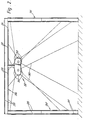
- Figure 1 is a schematic plan view of a laser-utilising facility within a safety enclosure ;
- Figure 2 is a side view, with the laser equipment omitted for clarity, and illustrating a basic form of hot spot monitoring arrangement.
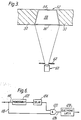
- Figure 3 is a plan view of part of a cave for remotely handling irradiated materials ;
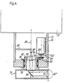
- Figure 4 is a schematic partly vertically-sectioned view showing a hot spot monitoring arrangement having a scanning facility ;
- Figure 5 is a circuit block diagram of signal processing circuitry for use with the arrangement of Figure 4 ;
- Figure 6 is a circuit diagram. corresponding to one of the timing circuits illustrated in the block diagram of Figure 5 ; and
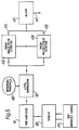
- Figure 7 is a block diagram of alternative signal processing circuitry for use with the scanning arrangement of Figure 4.
- As shown diagrammatically in Figure 1, the laser facility comprises a suitably enclosed
laser source 10 the beam of which is directed by means offlight tubes 12 and a switching mirror system 14 to one or other of twoworkstations Safety isolators 20 enable the laser beam to be blocked from entering the respective workstation enclosures. Thelaser source 10 is provided with ashutter device 22 which, when open, allows the beam into the beam line and can be closed, e. g. by a pneumatic double acting cylinder, to block entry of the laser beam into the flight tube system. - The facility is housed within a safety
enclosure comprising walls 24 andceiling 26 which may be of double-skinned construction comprisingcladding panels 28 of for example polycarbonate and/or steel materials attached to a supporting framework comprising, for instance, channel-section aluminium supports 30. As shown in Figure 2, thewalls 24 may comprise a lower section of steel cladding and an upper section of ≠ PERSPEX cladding, the latter providing viewing facilities. As previously mentioned, in a current design, the double-skinned walls are provided with a sandwich filling which consists of water in the upper sections of the walls and sand in the lower sections. Such fillings may not be necessary when the safety system according to the present invention is used. - As shown in Figure 2, a
monitoring system 32 is located within the safety enclosure and may for example be suspended from the ceiling. Themonitoring system 32 may comprise one or more infra-red sensors which may be responsive to radiation within the range of 3 to 5 microns and which, in conjunction with a suitable optical system including for instance a number oflenses 34, are arranged to view all of those internal surfaces upon which stray laser beam power might impinge in the event of fault conditions arising. A typical field of view is indicated by the lines depicted by numeral 36 in Figure 2. In the event of stray laser beam power impinging on any one of the surfaces being monitored, a hot spot will develop which will be promptly detected by the monitoring system. In such circumstances, the monitoring system feeds and output signal to control circuitry for modifying laser operation, e. g. by shutting the laser off and operating theshutter 22 to prevent entry of the beam into the flight tube system. - Referring to Figure 3, this illustrates an application of the invention to a cave for handling irradiated materials such as nuclear fuel elements which are to be dismantled by laser cutting techniques. The cave is fabricated with thick
concrete walls 50 in which aviewing window 52 is located. For present purposes thewindow 52 may be regarded as comprising an outer pane 54, andinner pane 56 facing inwardly of the cave and a body ofliquid 58 filling the space between the two panes. Within the cave there is a laser beam- utilising facility (not shown) which may comprise a laser tool such as a welding or metal cutting head mounted by remotely operable robotic equipment. To ensure that the laser beam does not impinge on the window either at all or at least for a length of time sufficient to risk penetration of the inner pane (and hence loss of liquid and radiation shielding), the surface of the inner pane is monitored by means of an infra-red sensor device 60 the field of view of which is restricted by amask 62 so as to coincide with the perimeter of the window. Thus, the sensor device will only respond to the incidence of the laser beam on the window but not on thewalls 50. If the level of radiation sensed by thesensor 60 exceeds a predetermined threshold this condition is used to disable the laser in the manner described previously and, optionally, operate some form of warning device. - In the embodiments of Figures 1 to 3, the monitoring arrangements have a fixed field of view and, where the area to be monitored is extensive as in Figures 1 and 2, a scanning arrangement will in general be preferable. Figure 4 illustrates one form of scanning arrangement and comprises a fixed
upper housing 70, a fixedlower housing 72 and ascanning head 74. Theupper housing 70 may for example be secured at a suitable vantage point to the ceiling of a safety enclosure such as that illustrated in Figures. 1 and 2 and may accommodate electronic circuitry (to be described below) and power supply circuitry for the electronics and anelectric drive motor 76 housed within thelower housing 72. The base of thelower housing 72 rotatably mounts, viabearings 78, atubular shaft 80 to the lower end of which thescanning head 74 is secured. Themotor 76 and theshaft 80 are coupled by a belt and pulley drive 82, 84 so that the scanning head can be scanned around theaxis 86. - An infra-
red sensor 88, e. g. a lead selenide- cell, is mounted along theaxis 86 byarm 89 which may be fixed to thelower housing 72 as shown or may be connected to the drivenpulley 82 orshaft 80. Infra-red radiation from the surroundings is collected by an optical system and focussed on thesensor 88. Thus, as illustrated, the optical system comprises awide angle lens 90 arranged so that its wide angle of view extends in a plane which contains or is parallel to theaxis 86, a beam- folding mirror 92 and a focussinglens 94 all mounted for rotation with the scanning head 74 (although it is not essential for thelens 94 to rotate with the scanning head). Thelens 90 is a cylindrical anamorphic lens and the opticalsystem comprising sensor 88,lenses sensor 88 is located at the focal surface oflens 94 so that, in the horizontal section in whichlens 90 has no power, thesensor 88 andlens 94 define the horizontal field angle of the instantaneous field as w/f radians (where w is the width of the sensor and f is the focal length of lens 94). Thelens 90 has the effect of extending the range of angles from which radiation reaches the sensor, in the vertical section, to 180°. As thescanning head 74 rotates (typically at a speed giving at least one complete scan per second), the field of view provided by the optical system is passed through 360° thereby giving a very extensive overall field of view, i. e. 360° in a horizontal plane and, in the illustrated embodiment, 180° in a vertical plane. - In many situations, a single scanning arrangement such as that shown in Figure 4 will suffice ; however, if needed to provide adequate coverage, an additional scanning arrangement or arrangements as illustrated in Figure 4 may be provided so that the scanning arrangements collectively provide coverage of all potentially vulnerable surfaces. In the embodiment illustrated in Figure 4, the
cylindrical lens 90 subtends 180° in a vertical plane but a lesser angle may be adequate for some applications in which only certain surfaces are vulnerable and in this event thelens 90 may be masked to limit the viewing angle as required. - The scanning speed is controllable by the
motor 76 and, if desired, may be selectively variable by varying the motor speed, e. g. by way of operator-actuable controls. The speed of scanning will in turn govern the degree of temperature resolution achievable, i. e. the slower the scanning speed the higher the temperature resolution achievable. By permitting variation in scanning speed, the monitoring equipment can be used both for rapidly detecting hot spots generated by laser beam impingement on enclosure surfaces (in which case, high scanning speeds are appropriate) and detecting other conditions leading to less substantial increases in infra-red radiation emission (in which case, slower scanning speeds are appropriate). Thus, for example, in general safeguards are necessary to ensure that personnel are excluded from the safety enclosure during laser operation. The presence of personnel within the enclosure can be detected by virtue of the level of infra-red radiation emitted and such radiation levels can be detected with the aid of slower scanning speeds. If necessary, two scanning arrangements may be employed which operate at scanning speeds compatible with hot spot and personnel detection respectively (using different threshold levels for radiation detection) so that if either scanning arrangement registers the condition monitored, i. e. development of a hot spot or presence of personnel, appropriate disabling of laser operation is initiated accompanied by generation of an alarm signal. Alternatively, as described hereinafter, the same scanning arrangement may be used to monitor both types of condition. Typically the fast scan rate will be greater than one complete scan per second and may be of the order of a scan every 100 milliseconds, while the slow scan rate may be of the order of several seconds. - Although as shown in Figure 4, the instantaneous field of view provided by the optical system is of greatly extended configuration (the long and short dimensions being in a ratio of at least 50 : and typically of the order of 120 1 to 220:1), a compact instantaneous field of view (i. e. having mutually orthogonal dimensions of the same order) may be employed by arranging for the latter to be scanned in mutually orthogonal planes using expedients such as continuously rotating mirror polygons or mirrors driven angu- lady by gaivonometers, typically providing linear ramp deflection with fast flyback. Thus, for example, a rotating mirror polygon may be used to generate a rapid scan in a vertical plane while the mirror polygon is panned at a slower rate about a vertical axis (e. g. 30-60 rpm). However, the use of an extended instantaneous field of view as in Figure 4 is preferred since the mechanical drive arrangement can be simpler and high speed movements of optical components are not required.
- Figure 5 illustrates diagrammatically electronic circuitry for processing the outputs of the
sensor 88. Thesensor 88 is connected to apre-amplifier circuit 96 and the amplified output is connected to one input of alevel comparator 98 having a second input connected to acircuit 100 providing a reference threshold value which may be selectively variable and will in general be preset to a value corresponding to the maximum infra-red emissions acceptable, i. e. so that a hot spot resulting from impingement of an errant laser beam on a wall of the enclosure is readily distinguishable from normal background levels of infra-red emission in the work area. If the input from thesensor 88 exceeds the preset threshold value, thecomparator 98 provides an output which is fed to two timingcircuits respective outputs sensor 88 or electronics. The circuit 110 also initiates, via output 112, appropriate disabling of laser operation as previously described. - The safeguard against malfunctioning of the
sensor 88 or electronics is implemented by deliberately providing ahot reference source 114 at a known position within the overall field of view traversed during each scan. For example, a hot spot constituted by an electrical resistance- heated component may be located at a suitable vantage point within the enclosure so that thesensor 88 sees the referencehot spot 114 once on every scan. The twotiming circuits hot spot 114 and any undesirable hot spots. In addition, thetiming circuit 102 establishes that the reference hot spot is actually seen by thesensor 88 during each and every scan. Thetiming circuit 102 may comprise a retriggerable monostable having a time-out period exceeding the scanning period so that, provided the reference hot spot is detected during each scan, it is repeatedly retriggered (without timing out) by the outputs produced bycomparator 98 in response to the reference hot spot If, however,circuit 102 does time out this indicates failure to detect the reference hot spot within a scan cycle and hence initiates generation of the alarm and disabling of laser operation by circuit 110. If desired,circuit 102 may be arranged so that an output to circuit 110 is provided only if the reference hot spot fails to be detected on two or more occasions in successive scan cycles (or for example during two out of three scan cycles). - The
timing circuit 104 may include a monostable triggered by the signal derived from the referencehot spot 114 and having a time out period slightly less than the scanning period and may be arranged to be armed during this timing period so as to detect hot spots other than the reference. Thus, for example, thetiming circuit 104 may be implemented, in principle, in the manner indicated in Figure 6. The output from thecomparator 98 is fed vialines 116, 118 to monostable 122 and one input of an ANDgate 120. On being triggered, the monostable 122 maintains an output for its timing period at the second input of ANDgate 120, the monostable output being delayed bydelay circuit 124 to stop the triggering pulse arriving subtantially simultaneously atgate 120 via the two routes so thatgate 120 does not give a spurious coincidence output online 126 at this stage. If a second hot spot is not detected within the timing period of monostable 122 the latter times out, removes the output applied at the second input ofgate 120 and awaits retriggering by the next pulse derived from the referencehot spot 114. If however a second hot spot is detected before monostable 122 times out, the resulting pulse will be routed to the first input ofgate 120 via line 118 and the resulting coincidence of pulses at both inputs ofgate 120 will produce an output online 126 which is effective to operate electronic latch 128 and provide a signal for initiating operation of the alarm/disabling initiating circuit 110. It will be seen that the referencehot spot 114 serves to trigger bothcircuits motor 76 andshaft 80. In this event, sighting of the reference hot spot will be shifted relative to the timing periods of the timingcircuits circuits - The scanning arrangement of Figure 4 may be used in conjunction with sampling-type electronic circuitry to obtain greater flexibility in monitoring of infra-red emissions. One implementation of such circuitry is shown schematically in Figure 7. A position encoder 130 is associated with the scanning unit of Figure 4 (here depicted by reference numeral 140) to provide an electrical output representative of the instantaneous point reached during each scanning cycle. The encoder 130 may comprise a proximity detector or
optoelectronic switch 132 co-operable with a toothed disc 134 (see Figure 4) carried by the drive shaft of themotor 76 so that the proximity detector or opto-switch provides a series of for example 256 pulses during each scanning cycle. The encoder may be responsive to rotation of the scanning head per se if desired so as to eliminate errors such as drive belt slip. - The outputs of the
sensor 88 and encoder are fed to signalprocessing electronics 136 which may be microprocessor based. Adigital memory 138 serves to store a reference temperature profile for the overall field of view under surveillance, the store being loaded with a digital value associated with a respective one of the series of instantaneous fields (e. g. 256 such values) produced during scanning. During surveillance, the output produced by thesensor 88 is repeatedly sampled (e. g. 256 times per cycle) and is fed to acomparator 142 along with the corresponding reference value from thememory 138 and, if the difference exceeds a predetermined threshold derived fromthreshold store 144 during any scan or more than once in two or more scans, adevice 146 is operated for initiating an alarm and disabling laser operation. - Typically, the scanning period will be of the order of one second or less and the interval between production of an output by the detector and operation of the warning device may be less than one second. Thus, appropriate remedial action can be taken rapidly before any hazard develops since the output of the
comparator 142 is employed to disable or otherwise modify operation of the laser. - As a safety measure, as described with reference to Figure 6, a reference hot spot may be secured to a suitable fixture within the field of view (i. e. on a wall or other structure) to provide a self-check facility for the scanning unit. Thus, the reference « hot spot should be sighted by the scanning unit at a particular point in each scan and failure to sight the reference « hot spot may be used to initiate a warning signal. The reference « hot spot also provides a geographical reference point within the scanning field to facilitate the identification of particular discrete zones or areas at which an alarm condition may be detected.
- The reference temperature profile collectively provided by the digital values stored in the
memory 138 may be obtained by initially using thescanning unit 140 to scan the area under surveillance in circumstances where any potential hazard is known not to exist, e. g. prior to energising, or during correct operation of, the laser equipment. Thus, the output ofsensor 88 can be sampled for each increment in the overall scan and the values obtained may be entered at appropriate addresses in thememory 138 for retrieval at corresponding points in subsequent scans and hence for comparison bycomparator 142 with the sampled outputs then prevailing for each such position. - The
threshold store 144 may contain more than one threshold value so that, in the course of comparisons made by thecomparator 142, different threshold values may be used for different sampling positions during the scan. The reference profile stored bymemory 138 may if desired be updated by thesignal processing electronics 136 at regular intervals by substituting the currently derived sample values for the previously stored values. Such updating can be effected each time a scan is executed but will more usually be effected at longer intervals, e. g. once every 60 minutes. - The signal processing electronics may process the sampled outputs from the
sensor 88 in two modes. In a first mode, the samples may be compared individually with corresponding stored reference values so that the circuitry can respond immediately to any large temperature variations resulting from the development of a hot spot In a second mode which affords a higher degree of temperature resolution, the sampled outputs may be analysed using an averaging technique whereby the samples are averaged over a relatively prolonged interval of time compared with the sampling interval and, in this mode, thecomparator 142 may be operable to compare the averaged value with a relatively low threshold value derived fromstore 144, for example in order to detect sources other than laser-initiated hot spots. For instance, in the second mode (which, in effect, simulates a slower scanning rate) the unauthorised presence of personnel within the safety enclosure may be detected and, in this event, appropriate action can be taken involving generation of an alarm and disabling of laser operation. - Although shown mounted from a ceiling, the scanning arrangements described above may for example be mounted by means of a slender column or pole secured to the floor or other convenient mounting surface.
- Attention is drawn to the divisional application published as EP-A-0 311 148.
Claims (14)
Applications Claiming Priority (8)
| Application Number | Priority Date | Filing Date | Title |
|---|---|---|---|
| GB858504168A GB8504168D0 (en) | 1985-02-19 | 1985-02-19 | Safety enclosure |
| GB8504168 | 1985-02-19 | ||
| GB8507505 | 1985-03-22 | ||
| GB858507505A GB8507505D0 (en) | 1985-03-22 | 1985-03-22 | Safety systems for lasers |
| GB858528719A GB8528719D0 (en) | 1985-11-21 | 1985-11-21 | Heat radiation surveillance system |
| GB8528719 | 1985-11-21 | ||
| GB8602224 | 1986-01-30 | ||
| GB8602224A GB2171513B (en) | 1985-02-19 | 1986-01-30 | Safety system for laser-utilising facilities |
Related Child Applications (2)
| Application Number | Title | Priority Date | Filing Date |
|---|---|---|---|
| EP88118885A Division EP0311148A3 (en) | 1985-02-19 | 1986-02-05 | Apparatus for monitoring infra-red emissions |
| EP88118885.8 Division-Into | 1986-02-05 |
Publications (2)
| Publication Number | Publication Date |
|---|---|
| EP0200289A1 EP0200289A1 (en) | 1986-11-05 |
| EP0200289B1 true EP0200289B1 (en) | 1989-11-23 |
Family
ID=27449635
Family Applications (1)
| Application Number | Title | Priority Date | Filing Date |
|---|---|---|---|
| EP86300761A Expired EP0200289B1 (en) | 1985-02-19 | 1986-02-05 | Safety system for laser-utilising facilities |
Country Status (5)
| Country | Link |
|---|---|
| US (1) | US4730113A (en) |
| EP (1) | EP0200289B1 (en) |
| JP (1) | JPH0776999B2 (en) |
| DE (1) | DE3667036D1 (en) |
| GB (2) | GB2171513B (en) |
Families Citing this family (56)
| Publication number | Priority date | Publication date | Assignee | Title |
|---|---|---|---|---|
| JP2804027B2 (en) * | 1987-07-13 | 1998-09-24 | ファナック 株式会社 | Laser output correction method |
| GB8803623D0 (en) * | 1988-02-17 | 1988-03-16 | Atomic Energy Authority Uk | Scanning system |
| US4891499A (en) * | 1988-09-09 | 1990-01-02 | Texas Instruments Incorporated | Method and apparatus for real-time wafer temperature uniformity control and slip-free heating in lamp heated single-wafer rapid thermal processing systems |
| JP2771569B2 (en) * | 1988-12-29 | 1998-07-02 | ファナック 株式会社 | Laser processing equipment |
| US4989971A (en) * | 1989-07-14 | 1991-02-05 | Tektronix, Inc. | Automatic mask trigger for an optical time domain reflectometer |
| US5159200A (en) * | 1991-04-12 | 1992-10-27 | Walter Kidde Aerospace Inc. | Detector for sensing hot spots and fires in a region |
| US5301347A (en) * | 1991-10-30 | 1994-04-05 | The United States Of America As Represented By The Secretary Of The Air Force | Multi-system laser safety shutter controller |
| FR2690641B1 (en) * | 1992-04-30 | 1996-07-12 | Lectra Systemes Sa | SAFETY DEVICE FOR MACHINES USING A LASER BEAM AND METHOD FOR IMPLEMENTING SAME. |
| JPH0621547A (en) * | 1992-06-30 | 1994-01-28 | Hitachi Software Eng Co Ltd | Laser transmission control system and laser using communication system |
| US5355383A (en) * | 1992-12-03 | 1994-10-11 | The United States Of America As Represented By The Administrator Of The National Aeronautics And Space Administration | Method and apparatus for detection and control of prelasing in a Q-switched laser |
| CH687653A5 (en) * | 1994-03-17 | 1997-01-15 | Von Roll Umwelttechnik Ag | Brandueberwachungssystem. |
| US5643477A (en) * | 1995-06-30 | 1997-07-01 | Motoman Inc. | Laser enclosure |
| FR2747065B1 (en) * | 1996-04-05 | 1998-06-12 | Milly Daniel Paul | PROTECTION DEVICE FOR LASER TABLE |
| DE19629037C1 (en) * | 1996-07-18 | 1997-07-31 | Erwin Martin Heberer | Element of protection wall against laser radiation |
| DE19710901C1 (en) * | 1997-03-15 | 1998-08-13 | Roland Man Druckmasch | Appliance for producing sleeve-type printing form from original sheet |
| DE19736042A1 (en) * | 1997-08-20 | 1999-02-25 | Alsthom Cge Alcatel | Device for longitudinal seam welding of metal pipes |
| ES2237197T3 (en) * | 1998-11-12 | 2005-07-16 | PALETTI PROFILSYSTEME GMBH & CO. | LASER RADIATION PROTECTION WALL. |
| US6147323A (en) * | 1999-08-05 | 2000-11-14 | Fanuc Robotics North America, Inc. | Passive laser enclosure |
| US7361171B2 (en) * | 2003-05-20 | 2008-04-22 | Raydiance, Inc. | Man-portable optical ablation system |
| US9022037B2 (en) * | 2003-08-11 | 2015-05-05 | Raydiance, Inc. | Laser ablation method and apparatus having a feedback loop and control unit |
| US20050279741A1 (en) * | 2004-06-17 | 2005-12-22 | Arenberg Jonathan W | Laser burn through sensor |
| US7910499B2 (en) | 2004-11-12 | 2011-03-22 | Applied Materials, Inc. | Autofocus for high power laser diode based annealing system |
| US7438468B2 (en) | 2004-11-12 | 2008-10-21 | Applied Materials, Inc. | Multiple band pass filtering for pyrometry in laser based annealing systems |
| US7129440B2 (en) | 2004-11-12 | 2006-10-31 | Applied Materials, Inc. | Single axis light pipe for homogenizing slow axis of illumination systems based on laser diodes |
| US7422988B2 (en) * | 2004-11-12 | 2008-09-09 | Applied Materials, Inc. | Rapid detection of imminent failure in laser thermal processing of a substrate |
| US8135050B1 (en) | 2005-07-19 | 2012-03-13 | Raydiance, Inc. | Automated polarization correction |
| US7135392B1 (en) | 2005-07-20 | 2006-11-14 | Applied Materials, Inc. | Thermal flux laser annealing for ion implantation of semiconductor P-N junctions |
| DE102005034110A1 (en) * | 2005-07-21 | 2007-01-25 | Füchtenkötter, Günter | Laser protective wall for shielding a laser area |
| US20070073610A1 (en) * | 2005-09-07 | 2007-03-29 | Prasad Marugabandhu | Job auction method and system |
| US7444049B1 (en) * | 2006-01-23 | 2008-10-28 | Raydiance, Inc. | Pulse stretcher and compressor including a multi-pass Bragg grating |
| US9130344B2 (en) * | 2006-01-23 | 2015-09-08 | Raydiance, Inc. | Automated laser tuning |
| US8232687B2 (en) | 2006-04-26 | 2012-07-31 | Raydiance, Inc. | Intelligent laser interlock system |
| US7822347B1 (en) | 2006-03-28 | 2010-10-26 | Raydiance, Inc. | Active tuning of temporal dispersion in an ultrashort pulse laser system |
| DE102006026555B4 (en) * | 2006-06-08 | 2008-04-30 | Ingenieurbüro Goebel GmbH | Method and device for detecting optical radiation |
| DE102006038795A1 (en) | 2006-08-18 | 2008-03-20 | Fft Edag Produktionssysteme Gmbh & Co. Kg | Monitoring device for a laser processing device |
| US7674999B2 (en) | 2006-08-23 | 2010-03-09 | Applied Materials, Inc. | Fast axis beam profile shaping by collimation lenslets for high power laser diode based annealing system |
| US7659187B2 (en) | 2006-11-03 | 2010-02-09 | Applied Materials, Inc. | Method of forming PN junctions including a post-ion implant dynamic surface anneal process with minimum interface trap density at the gate insulator-silicon interface |
| FR2914769B1 (en) * | 2007-04-06 | 2016-04-08 | Sagem Defense Securite | ACTIVE ACTIVE SOUND HEAD, WITH AXIS SCANNING, SLEEP SYSTEM COMPRISING THE PREFERRED HEAD AND A METHOD OF IMPLEMENTING THE HEAD AND THE SYSTEM |
| FR2914768B1 (en) * | 2007-04-06 | 2010-09-03 | Sagem Defense Securite | ACTIVE SOUND HEAD OF AN ENVIRONMENT WITH SCAN IN SITE, SLEEP SYSTEM COMPRISING THE HEAD ABOVE, AND METHOD FOR IMPLEMENTING THE HEAD AND SYSTEM |
| DE202007012255U1 (en) | 2007-08-31 | 2009-01-08 | Ingenieurbüro Goebel GmbH | Device for detecting optical radiation |
| US7903326B2 (en) | 2007-11-30 | 2011-03-08 | Radiance, Inc. | Static phase mask for high-order spectral phase control in a hybrid chirped pulse amplifier system |
| DE202008018087U1 (en) | 2008-04-02 | 2012-04-30 | Andreas Trautmann | Radiation protection element, radiation protection arrangement and computer system, data carrier and signal sequence |
| US8498538B2 (en) * | 2008-11-14 | 2013-07-30 | Raydiance, Inc. | Compact monolithic dispersion compensator |
| US9314877B2 (en) | 2010-01-27 | 2016-04-19 | Reis Group Holding Gmbh & Co. Kg | Assembly and method for detecting radiation |
| WO2012037465A1 (en) | 2010-09-16 | 2012-03-22 | Raydiance, Inc. | Laser based processing of layered materials |
| US8558156B2 (en) | 2010-10-27 | 2013-10-15 | The Boeing Company | Device for capturing and preserving an energy beam which penetrates into an interior of said device and method therefor |
| US10239160B2 (en) | 2011-09-21 | 2019-03-26 | Coherent, Inc. | Systems and processes that singulate materials |
| EP2886242B1 (en) * | 2013-12-20 | 2016-09-14 | TRUMPF Werkzeugmaschinen GmbH + Co. KG | Laser processing machine assembly, in particular with barrier free access |
| DE202014006310U1 (en) | 2014-08-05 | 2014-08-27 | Hochschule Mittweida (Fh) | Protection device for laser beams of at least one laser device |
| DE102014011716B3 (en) * | 2014-08-05 | 2015-12-24 | Hochschule Mittweida (Fh) | Protection device for laser beams of at least one laser device |
| DE202014006477U1 (en) | 2014-08-08 | 2014-09-05 | Hochschule Mittweida (Fh) | Protective wall for laser beams of at least one laser device |
| DE102014115304A1 (en) | 2014-10-21 | 2016-04-21 | Reis Gmbh & Co. Kg Maschinenfabrik | Method for monitoring a radiation |
| DE102017119148A1 (en) | 2017-06-15 | 2018-12-20 | Scansonic Mi Gmbh | Laser protection device and method for its operation |
| JP6904810B2 (en) * | 2017-06-29 | 2021-07-21 | コマツ産機株式会社 | Laser processing machine |
| CN110541731B (en) * | 2019-08-27 | 2021-10-22 | 山东科技大学 | Robot and method for intelligently monitoring and evaluating unsealing dangerous gas source of closed roadway of coal mine |
| DE102020132983B3 (en) | 2020-08-27 | 2022-02-10 | Alotec Dresden Gmbh | Mobile laser protection wall |
Family Cites Families (21)
| Publication number | Priority date | Publication date | Assignee | Title |
|---|---|---|---|---|
| US3101618A (en) * | 1960-11-15 | 1963-08-27 | Leeds & Northrup Co | Rotary kiln shell temperature scanning system |
| GB1003075A (en) * | 1963-04-11 | 1965-09-02 | Thring S Advanced Developments | Improvements in or relating to fire detection and alarm apparatus |
| GB1173161A (en) * | 1966-08-24 | 1969-12-03 | Imp Metal Ind Kynoch Ltd | Improvements in or relating to the Melting of Metal |
| US3924130A (en) * | 1968-02-12 | 1975-12-02 | Us Navy | Body exposure indicator |
| GB1280473A (en) * | 1968-07-04 | 1972-07-05 | Stewarts & Lloyds Ltd | Apparatus for detecting objects |
| FR2093399A5 (en) * | 1970-06-12 | 1972-01-28 | Commissariat Energie Atomique | |
| US3713042A (en) * | 1971-05-27 | 1973-01-23 | Bell Telephone Labor Inc | Stabilized mode-locked laser arrangement |
| US3869680A (en) * | 1973-08-31 | 1975-03-04 | Nasa | Dually mode-locked nd:yag laser |
| US3928843A (en) * | 1974-06-24 | 1975-12-23 | Optical Coating Laboratory Inc | Dual channel infrared intrusion alarm system |
| US4087691A (en) * | 1975-04-09 | 1978-05-02 | Aga Aktiebolag | Reference radiation source in a device for measuring the radiation from an object |
| FR2407784B1 (en) * | 1977-09-05 | 1982-02-26 | Peugeot | |
| JPS559258A (en) * | 1978-07-03 | 1980-01-23 | Murata Manufacturing Co | Invader monitor device |
| JPS57156887A (en) * | 1981-03-25 | 1982-09-28 | Toshiba Corp | Laser working device |
| GB2102200B (en) * | 1981-07-17 | 1985-05-30 | Philips Electronic Associated | Infra-red radiation detector |
| GB2125217B (en) * | 1982-08-06 | 1986-01-02 | Secr Defence | Infra red detector arrays |
| GB2108742B (en) * | 1982-09-27 | 1986-09-10 | Atomic Energy Authority Uk | Laser safety screen |
| EP0107042B1 (en) * | 1982-10-01 | 1987-01-07 | Cerberus Ag | Infrared detector for spotting an intruder in an area |
| JPS5997788A (en) * | 1982-11-26 | 1984-06-05 | Matsushita Electric Ind Co Ltd | Laser working machine |
| FR2541484B1 (en) * | 1983-01-13 | 1986-06-13 | Brown De Colstoun Francois | METHOD FOR THE DETECTION OF A SOURCE OF HEAT IN PARTICULAR OF A FOREST FIRE IN A MONITORED AREA, AND SYSTEM FOR CARRYING OUT SAID METHOD |
| JPS6012527A (en) * | 1983-07-04 | 1985-01-22 | Secoh Giken Inc | Infrared beam scanner |
| DE3340427C2 (en) * | 1983-11-09 | 1985-10-03 | Wandel & Goltermann Gmbh & Co, 7412 Eningen | Method for the safe operation of a device that contains a laser and a light-emitting interface that can be connected to a transmission medium, as well as a safety device for carrying out this method |
-
1986
- 1986-01-30 GB GB8602224A patent/GB2171513B/en not_active Expired
- 1986-01-30 GB GB8806624A patent/GB2203539B/en not_active Expired
- 1986-02-05 EP EP86300761A patent/EP0200289B1/en not_active Expired
- 1986-02-05 DE DE8686300761T patent/DE3667036D1/en not_active Expired
- 1986-02-07 US US06/827,098 patent/US4730113A/en not_active Expired - Fee Related
- 1986-02-19 JP JP61034960A patent/JPH0776999B2/en not_active Expired - Lifetime
Also Published As
| Publication number | Publication date |
|---|---|
| GB2171513B (en) | 1989-08-31 |
| GB2171513A (en) | 1986-08-28 |
| GB2203539B (en) | 1989-08-31 |
| DE3667036D1 (en) | 1989-12-28 |
| GB8806624D0 (en) | 1988-04-20 |
| GB2203539A (en) | 1988-10-19 |
| US4730113A (en) | 1988-03-08 |
| JPH0776999B2 (en) | 1995-08-16 |
| GB8602224D0 (en) | 1986-04-16 |
| JPS61259397A (en) | 1986-11-17 |
| EP0200289A1 (en) | 1986-11-05 |
Similar Documents
| Publication | Publication Date | Title |
|---|---|---|
| EP0200289B1 (en) | Safety system for laser-utilising facilities | |
| EP0059593B1 (en) | Method of and apparatus for monitoring gaseous pollutants | |
| CN101040173B (en) | Mems based space safety infrared sensor apparatus and method for detecting a gas or vapor | |
| US4952911A (en) | Scanning intrusion detection device | |
| CN101040304B (en) | Mems based space safety infrared sensor apparatus and method | |
| EP0319345A2 (en) | High power laser beam intensity mapping apparatus | |
| WO1989011707A1 (en) | A method of intrusion detection over a wide area | |
| EP0630510B1 (en) | Infrared intrusion sensor | |
| US4809314A (en) | Method of aligning a linear array X-ray detector | |
| JP3830050B2 (en) | Method and apparatus for monitoring hydrogen gas and hydrogen flame | |
| US20010052572A1 (en) | Directivity-type radiation detecting apparatus | |
| US3749928A (en) | Alarm device using infrared emission for detection and warning of heat build-up | |
| US3805064A (en) | Radiation sensitive intrusion detection system | |
| EP0311148A2 (en) | Apparatus for monitoring infra-red emissions | |
| US20210007342A1 (en) | Device and method for subjecting a flying insect to lethal radiation | |
| JPH07160956A (en) | Intrusion supervisory equipment | |
| US6035010A (en) | Monitor for measuring both the gamma spectrum and neutrons emitted by an object, such as spent nuclear fuel | |
| EP0421032A1 (en) | Scanning system | |
| CN112285758B (en) | Nuclear radiation field probe, detector and detection system | |
| JPH08510064A (en) | Equipment used with radiation shielding enclosures | |
| KR100492189B1 (en) | Discernment device for far distance fire confirmation | |
| JP2523948B2 (en) | Pyroelectric infrared detector | |
| CN216211444U (en) | Fire smoke detection device | |
| RU2765549C1 (en) | Active automated security system of a laser processing technological complex | |
| GB2186970A (en) | Safety system for iaser-utilising facility |
Legal Events
| Date | Code | Title | Description |
|---|---|---|---|
| PUAI | Public reference made under article 153(3) epc to a published international application that has entered the european phase |
Free format text: ORIGINAL CODE: 0009012 |
|
| AK | Designated contracting states |
Kind code of ref document: A1 Designated state(s): DE FR IT NL SE |
|
| 17P | Request for examination filed |
Effective date: 19870324 |
|
| 17Q | First examination report despatched |
Effective date: 19880704 |
|
| GRAA | (expected) grant |
Free format text: ORIGINAL CODE: 0009210 |
|
| AK | Designated contracting states |
Kind code of ref document: B1 Designated state(s): DE FR IT NL SE |
|
| XX | Miscellaneous (additional remarks) |
Free format text: TEILANMELDUNG 88118885.8 EINGEREICHT AM 05/02/86. |
|
| ITF | It: translation for a ep patent filed |
Owner name: JACOBACCI & PERANI S.P.A. |
|
| ET | Fr: translation filed | ||
| REF | Corresponds to: |
Ref document number: 3667036 Country of ref document: DE Date of ref document: 19891228 |
|
| PLBE | No opposition filed within time limit |
Free format text: ORIGINAL CODE: 0009261 |
|
| STAA | Information on the status of an ep patent application or granted ep patent |
Free format text: STATUS: NO OPPOSITION FILED WITHIN TIME LIMIT |
|
| 26N | No opposition filed | ||
| PGFP | Annual fee paid to national office [announced via postgrant information from national office to epo] |
Ref country code: SE Payment date: 19950118 Year of fee payment: 10 |
|
| PGFP | Annual fee paid to national office [announced via postgrant information from national office to epo] |
Ref country code: FR Payment date: 19950127 Year of fee payment: 10 Ref country code: DE Payment date: 19950127 Year of fee payment: 10 |
|
| EAL | Se: european patent in force in sweden |
Ref document number: 86300761.3 |
|
| ITTA | It: last paid annual fee | ||
| PGFP | Annual fee paid to national office [announced via postgrant information from national office to epo] |
Ref country code: NL Payment date: 19950228 Year of fee payment: 10 |
|
| PG25 | Lapsed in a contracting state [announced via postgrant information from national office to epo] |
Ref country code: SE Effective date: 19960206 |
|
| PG25 | Lapsed in a contracting state [announced via postgrant information from national office to epo] |
Ref country code: NL Effective date: 19960901 |
|
| PG25 | Lapsed in a contracting state [announced via postgrant information from national office to epo] |
Ref country code: FR Effective date: 19961031 |
|
| NLV4 | Nl: lapsed or anulled due to non-payment of the annual fee |
Effective date: 19960901 |
|
| PG25 | Lapsed in a contracting state [announced via postgrant information from national office to epo] |
Ref country code: DE Effective date: 19961101 |
|
| REG | Reference to a national code |
Ref country code: FR Ref legal event code: ST |
|
| PG25 | Lapsed in a contracting state [announced via postgrant information from national office to epo] |
Ref country code: IT Free format text: LAPSE BECAUSE OF NON-PAYMENT OF DUE FEES;WARNING: LAPSES OF ITALIAN PATENTS WITH EFFECTIVE DATE BEFORE 2007 MAY HAVE OCCURRED AT ANY TIME BEFORE 2007. THE CORRECT EFFECTIVE DATE MAY BE DIFFERENT FROM THE ONE RECORDED. Effective date: 20050205 |