EP0200419A2 - Two-piece heart valve holder-rotator - Google Patents
Two-piece heart valve holder-rotator Download PDFInfo
- Publication number
- EP0200419A2 EP0200419A2 EP86302837A EP86302837A EP0200419A2 EP 0200419 A2 EP0200419 A2 EP 0200419A2 EP 86302837 A EP86302837 A EP 86302837A EP 86302837 A EP86302837 A EP 86302837A EP 0200419 A2 EP0200419 A2 EP 0200419A2
- Authority
- EP
- European Patent Office
- Prior art keywords
- plug
- legs
- heart valve
- prosthesis
- grip
- Prior art date
- Legal status (The legal status is an assumption and is not a legal conclusion. Google has not performed a legal analysis and makes no representation as to the accuracy of the status listed.)
- Withdrawn
Links
- 210000003709 heart valve Anatomy 0.000 title claims abstract description 37
- 238000002513 implantation Methods 0.000 claims description 9
- 230000000087 stabilizing effect Effects 0.000 claims 1
- 239000000463 material Substances 0.000 description 3
- 239000008280 blood Substances 0.000 description 2
- 210000004369 blood Anatomy 0.000 description 2
- 230000017531 blood circulation Effects 0.000 description 2
- 230000000295 complement effect Effects 0.000 description 2
- 238000003780 insertion Methods 0.000 description 2
- 230000037431 insertion Effects 0.000 description 2
- 239000002296 pyrolytic carbon Substances 0.000 description 2
- 210000001519 tissue Anatomy 0.000 description 2
- 239000004677 Nylon Substances 0.000 description 1
- 206010067171 Regurgitation Diseases 0.000 description 1
- 230000004087 circulation Effects 0.000 description 1
- 239000000470 constituent Substances 0.000 description 1
- 238000010276 construction Methods 0.000 description 1
- 230000002950 deficient Effects 0.000 description 1
- 230000001419 dependent effect Effects 0.000 description 1
- 239000004744 fabric Substances 0.000 description 1
- 210000005003 heart tissue Anatomy 0.000 description 1
- 230000003100 immobilizing effect Effects 0.000 description 1
- 239000007943 implant Substances 0.000 description 1
- 238000011065 in-situ storage Methods 0.000 description 1
- 239000002184 metal Substances 0.000 description 1
- 238000012986 modification Methods 0.000 description 1
- 230000004048 modification Effects 0.000 description 1
- 229920001778 nylon Polymers 0.000 description 1
- 229920002492 poly(sulfone) Polymers 0.000 description 1
- 238000005086 pumping Methods 0.000 description 1
- 239000012858 resilient material Substances 0.000 description 1
- 230000035939 shock Effects 0.000 description 1
- 229910001220 stainless steel Inorganic materials 0.000 description 1
- 239000010935 stainless steel Substances 0.000 description 1
Images
Classifications
-
- A—HUMAN NECESSITIES
- A61—MEDICAL OR VETERINARY SCIENCE; HYGIENE
- A61F—FILTERS IMPLANTABLE INTO BLOOD VESSELS; PROSTHESES; DEVICES PROVIDING PATENCY TO, OR PREVENTING COLLAPSING OF, TUBULAR STRUCTURES OF THE BODY, e.g. STENTS; ORTHOPAEDIC, NURSING OR CONTRACEPTIVE DEVICES; FOMENTATION; TREATMENT OR PROTECTION OF EYES OR EARS; BANDAGES, DRESSINGS OR ABSORBENT PADS; FIRST-AID KITS
- A61F2/00—Filters implantable into blood vessels; Prostheses, i.e. artificial substitutes or replacements for parts of the body; Appliances for connecting them with the body; Devices providing patency to, or preventing collapsing of, tubular structures of the body, e.g. stents
- A61F2/0095—Packages or dispensers for prostheses or other implants
-
- A—HUMAN NECESSITIES
- A61—MEDICAL OR VETERINARY SCIENCE; HYGIENE
- A61F—FILTERS IMPLANTABLE INTO BLOOD VESSELS; PROSTHESES; DEVICES PROVIDING PATENCY TO, OR PREVENTING COLLAPSING OF, TUBULAR STRUCTURES OF THE BODY, e.g. STENTS; ORTHOPAEDIC, NURSING OR CONTRACEPTIVE DEVICES; FOMENTATION; TREATMENT OR PROTECTION OF EYES OR EARS; BANDAGES, DRESSINGS OR ABSORBENT PADS; FIRST-AID KITS
- A61F2/00—Filters implantable into blood vessels; Prostheses, i.e. artificial substitutes or replacements for parts of the body; Appliances for connecting them with the body; Devices providing patency to, or preventing collapsing of, tubular structures of the body, e.g. stents
- A61F2/02—Prostheses implantable into the body
- A61F2/24—Heart valves ; Vascular valves, e.g. venous valves; Heart implants, e.g. passive devices for improving the function of the native valve or the heart muscle; Transmyocardial revascularisation [TMR] devices; Valves implantable in the body
- A61F2/2427—Devices for manipulating or deploying heart valves during implantation
Definitions
- the present invention is directed to a device for holding a mechanical heart valve prosthesis both during shipment and during implantation.
- Surgically-implanted heart valve prostheses of the mechanical type have extended the life expectancy of many patients who had defective natural valves.
- Such prostheses are essentially check valves having a valve body that provides a blood flow passageway and an occluder, in the form of either one or two leaflets, that shifts to alternatively open the passageway, in response to blood flow in the circulation direction, and close the passageway, to prevent regurgitation of blood therethrough when the pumping action of the heart produces a localized back pressure.
- the heart valve body is generally formed from a rigid material, such as metal or pyrolytic carbon, and is commonly provided with a suture ring permanently secured thereto for attaching the valve body to the tissues of the heart.
- specialized holders have been developed that enable a surgeon to precisely position the heart valve and the suture ring within the heart passageway and to securely hold the assembly in place until suturing has been effected. It is desirable that such holders provide a quick, sure release of the sutured valve without placing undue strain on the tissue sutured to the prosthesis, and also that the holder be re-engageable with the valve body after the release thereof if repositioning of the valve is required.
- prostheses and their associated holders are frequently assembled by the manufacturer and shipped singly in sterile enclosures.
- the assembly be stably held within the enclosure, and, more particularly, that the motion of the valve leaflets be sufficiently restricted so as to prevent any unnecessary wear on the prosthesis due to the shifting of the leaflets during transportation.
- a two-piece heart valve holder engageable by a separate handle for positioning and rotating the heart valve.
- the holder includes a cylindrically-shaped plug member that has a recessed shoulder at one end sized to fit within the inside surface of the body of the heart valve prosthesis.
- the other end of the cylindrical plug is in the form of a V-shaped seat.
- Two passages extend through the plug member parallel with the axis thereof, and extending upwardly from the periphery of the seat adjacent each of the passages is a wall or shoulder.
- a separate grip member includes two legs, each sized in length to extend through the passageways in the plug member.
- the two legs each include a base member to which each leg is respectively connected at an angle inward from the outer edge of the base member substantially equal to the angle between each half of the V-shaped seat and a plane perpendicular to the axis of the plug member.
- the two base members are hinged together with the legs inherently biased outward at an angle complementary to that of the V-shaped seat so that the legs are substantially parallel when the grip is in its natural condition.
- each leg has an outwardly projecting foot at the distal end thereof.
- the legs of the grip member are deflected inwardly and inserted into the passageways of the plug member.
- the feet are able to spring outwardly to engage the lower edge of the prosthesis. Additional camming force to bias the legs outwardly is provided by the walls on the seat adjacent the passageways, thus maintaining the legs substantially parallel to the axis of the plug member and the feet on each leg in engagement with the edge of the valve body of the prosthesis to prevent its removal from the plug member.
- the prosthesis, plug member and grip member are sterilized and shipped in this assembled condition in a hermetically sealed enclosure.
- the plug member receives a handle for positioning and rotating the valve pursuant to its implantation.
- the grip member is released by lifting a tab that extends upwardly from one of the base members. As the base members are lifted, the legs are forced inwardly and the feet are retracted from engagement with the edge of the valve body. The plug is disengaged from the valve by Lifting the plug member with the handle.
- FIG. 1 shows a two-part holder and prosthesis that may be assembled in accordance with the present invention to facilitate the shipping and implantation of the prosthesis.
- the holder includes a plug member (which may be molded from polysulphone or a similar material), generally indicated by 10, and a grip member (preferably molded from nylon), generally indicated by 11, with the heart valve prosthesis indicated by 12.
- a plug member which may be molded from polysulphone or a similar material
- a grip member preferably molded from nylon
- the operation of the prosthesis 12 and the constituent parts 10, 11, of the holder is not dependent upon their orientation (the prosthesis being oriented according to the anatomical configuration of the heart), for ease of explanation, the invention will be described with reference to the vertical orientation shown in the drawings.
- the heart valve prosthesis 12 is substantially configured as described in Klawitter U.S. No. 4,413,894, which is herein incorporated by reference, and includes an annular valve body 14 having a central passageway therethrough. Pivotally disposed within the valve body 14 are a pair of leaflets 15 that are movable between open (as shown) and closed positions to either permit or restrict the flow of blood therethrough.
- the valve body 14 and leaflets 15 are made of a biocompatible, thromboresistant material, such as pyrolytic carbon.
- the central passageway of the valve body 14 has a generally circular interior wall 16 (best seen in FIG.
- a suture ring 20 for attaching the prosthesis to the heart tissue is applied around the valve body 14 and typically comprises an annulus having an outer fabric layer that receives the sutures.
- the plug member 10 of the holder is substantially cylindrical in shape and includes a recessed shoulder 21 at its lower end sized to fit within the upper end of the interior wall 16 of the valve body 14.
- the shoulder 21 includes two diametrically-opposed flat sections, one of which is seen at 22 (FIG. 1), that complement the flat portions on the interior wall 16 of the valve body 14.
- the grip member 11 includes two diametrically-opposed legs 24 that are sized in length to extend through diametrically-opposed passages 25 in the plug member 10, such passageways 25 being parallel to the longitudinal axis Y of the plug member 10.
- Each leg 24 depends from a base member 26 and each has an outwardly projecting foot 28 that engages the lower edge of the valve body 14 of the prosthesis, as best seen in FIGS. 3 and 5.
- a radial projection 29 that engages the underside of the land created by the enlarged diameter 19 of the interior wall 16 of the valve body 14.
- each leg 24 is angled inwardly from the outer edge of its base member 26 at an angle a (See FIG. 1).
- the upper end of the plug 10 is shaped so as to not interfere with the relaxed configuration of the grip 11 in which the legs 24 are biased outwardly.
- the upper end of the plug member 10 terminates in a V-shaped seat 30 in which each half of the V extends upwardly from the horizontal at an angle b (FIG. 1) substantially equal to the angle a between each base member 26 and its respective leg 24.
- the two base members 26 are joined by a flexible hinge 31 that, when the legs 24 of the grip member 11 are inserted into the passageways 25 in the plug member 10, overlies the apex 32 of the V-shaped seat 30.
- the grip member 11 is unitary, with the hinge 31 formed by an area of reduced cross-section resilient material having a substantially U-shape, best seen in FIGS. 1 and 3.
- the two legs 24 are substantially parallel, as shown in FIG. 1, and, when the legs 24 extend through the passageways 25 in the plug, the feet 28 will automatically move radially outwardly to engage the lower end of the valve body 14.
- Additional outward camming force is provided by the inner faces of shoulders or walls 27 that extend upwardly from the periphery of the seat 30 adjacent the passages 25. Contact of the base members 26 with the walls 27 ensures that the base members are maintained in their natural position, thus maintaining the legs 24 in parallel relation so that the feet 28 engage the lower edge of the valve body 14.
- the sterile assembly is ready to be packaged for shipment.
- the legs 24 extend through the passageway of the prosthesis in such a manner that the leaflets 15 of the valve 12 are prevented from closing against the inside of the valve body 14 (See FIG. 4). This helps to reduce unnecessary wear on the prosthesis 12 prior to implantation and protects against possible damage caused by shock during shipment.
- the enclosure may contain a thin, C-shaped lock ring or plate (not shown), within which the assembly is captured by the facing edges of the "C".
- the exterior of the plug 10 includes two opposed slots or grooves 34, best seen in FIGS. 3 and 4, the slots 34 being formed perpendicular to the longitudinal axis Y of the plug 10 and being sized in width to frictionally capture the facing central edges of the lock plate.
- a separate handle 35 (FIG. 5) is provided with each prosthesis 12.
- the handle 35 is preferably made of stainless steel and includes an elongated shaft 36 that is easily bendable to suit the anatomical requirements of the implant site.
- the shaft 36 terminates in resilient prongs 38 whose hooked ends snap into a recess 39 which is provided at the bottom of a square hole 40 that extends along the longitudinal axis Y of the plug member 10.
- Formed in the base members 26 of the grip member 11 is a circular hole 41 (FIG. 2) to provide access from above to the square hole 40 of the plug member 10 required for insertion of the handle 35.
- the handle 35 is provided with a collar 42, having a flat lower end for abutting a flat upper surface of a cylindrical projection 44 on the otherwise V-shaped seat 30 of the plug 10, the upper opening of the square hole 40 being encircled by the projection 44.
- the grip member 11 is provided with an upwardly projecting tab 45.
- one such tab 45 is provided on each base member 26.
- the tabs 45 are disposed diametrically on the grip 11 along opposite sides of the hinge 31. Release of the grip 11 is effected by holding the handle 35 (thus immobilizing the plug 10) and pulling on one of tabs 45 with a forceps 46 or the like (FIG. 5) to unseat the base members 26 from engagement with the inner surface of the walls 27 and cam the legs 24 inwardly, thus forcing the feet 28 out of engagement with the lower end of the valve body 14.
- the grip 11 may be discarded and the prosthesis 12 unseated from the plug 10 by lifting on the handle 35.
- the plug 10 may be reseated in the prosthesis 12 by aligning the flats 22 on the recessed shoulder 21 of the plug 10 with the flats on the interior wall 16 of the valve body 14.
- the handle 35, plug 10 and prosthesis 12 may then be rotated in unison to reorient the prosthesis 12.
- the plug 10 is withdrawn by the handle 35, and the plug 10 and the handle 35 may be discarded.
- a holder for a heart valve prosthesis has been provided that fully meets the above-stated objects. While the holder has been described in terms of a preferred embodiment, it will be understood that there is no intent to limit the invention by such disclosure. Rather, it is intended to cover all modifications and constructions falling within the spirit and scope of the invention as defined in the appended claims.
- the tabs 45 may also be received in slots in the shipping enclosure to further stabilize the assembly during shipment.
- the preferred embodiment has a V-shaped seat
- the seat may be of any shape that does not interfere with the relaxed, outwardly biased condition of the grip in which the legs will naturally engage the prosthesis upon the insertion of the legs through the passages in the plug.
Abstract
Description
- The present invention is directed to a device for holding a mechanical heart valve prosthesis both during shipment and during implantation.
- Surgically-implanted heart valve prostheses of the mechanical type have extended the life expectancy of many patients who had defective natural valves. Such prostheses are essentially check valves having a valve body that provides a blood flow passageway and an occluder, in the form of either one or two leaflets, that shifts to alternatively open the passageway, in response to blood flow in the circulation direction, and close the passageway, to prevent regurgitation of blood therethrough when the pumping action of the heart produces a localized back pressure. The heart valve body is generally formed from a rigid material, such as metal or pyrolytic carbon, and is commonly provided with a suture ring permanently secured thereto for attaching the valve body to the tissues of the heart.
- To facilitate the implantation of heart valve prostheses, specialized holders have been developed that enable a surgeon to precisely position the heart valve and the suture ring within the heart passageway and to securely hold the assembly in place until suturing has been effected. It is desirable that such holders provide a quick, sure release of the sutured valve without placing undue strain on the tissue sutured to the prosthesis, and also that the holder be re-engageable with the valve body after the release thereof if repositioning of the valve is required.
- For convenience, prostheses and their associated holders are frequently assembled by the manufacturer and shipped singly in sterile enclosures. During shipment of the assembly of the heart valve and holder, it is desirable that the assembly be stably held within the enclosure, and, more particularly, that the motion of the valve leaflets be sufficiently restricted so as to prevent any unnecessary wear on the prosthesis due to the shifting of the leaflets during transportation.
- Consequently, it is the principal object of the present invention to provide an improved device for holding a heart valve prosthesis both during shipment and during implantation.
- More particularly it is an object of the invention to provide such a heart valve holder that facilitates precise positioning of the prosthesis for suturing and easy release of the prosthesis after suturing has been completed.
- It is a further object of the invention to provide a heart valve holder that is re-engageable with the prosthesis after the release thereof so as to facilitate repositioning of the valve.
- It is another object of the invention to provide a heart valve holder that restricts the movement of the heart valve leaflets during shipment.
- These objects are met by a two-piece heart valve holder engageable by a separate handle for positioning and rotating the heart valve. The holder includes a cylindrically-shaped plug member that has a recessed shoulder at one end sized to fit within the inside surface of the body of the heart valve prosthesis. The other end of the cylindrical plug is in the form of a V-shaped seat. Two passages extend through the plug member parallel with the axis thereof, and extending upwardly from the periphery of the seat adjacent each of the passages is a wall or shoulder.
- A separate grip member includes two legs, each sized in length to extend through the passageways in the plug member. The two legs each include a base member to which each leg is respectively connected at an angle inward from the outer edge of the base member substantially equal to the angle between each half of the V-shaped seat and a plane perpendicular to the axis of the plug member. The two base members are hinged together with the legs inherently biased outward at an angle complementary to that of the V-shaped seat so that the legs are substantially parallel when the grip is in its natural condition. Further, each leg has an outwardly projecting foot at the distal end thereof. To secure a heart valve prosthesis fitted onto the recessed shoulder of the plug member, the legs of the grip member are deflected inwardly and inserted into the passageways of the plug member. When the legs extend through the passageways, the feet are able to spring outwardly to engage the lower edge of the prosthesis. Additional camming force to bias the legs outwardly is provided by the walls on the seat adjacent the passageways, thus maintaining the legs substantially parallel to the axis of the plug member and the feet on each leg in engagement with the edge of the valve body of the prosthesis to prevent its removal from the plug member.
- The prosthesis, plug member and grip member are sterilized and shipped in this assembled condition in a hermetically sealed enclosure. Upon removal from the shipping enclosure, the plug member receives a handle for positioning and rotating the valve pursuant to its implantation. Once the prosthesis is sutured in place, the grip member is released by lifting a tab that extends upwardly from one of the base members. As the base members are lifted, the legs are forced inwardly and the feet are retracted from engagement with the edge of the valve body. The plug is disengaged from the valve by Lifting the plug member with the handle.
- The following is a description of some specific embodiments of the invention reference being made to the accompanying drawings in which:
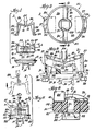
- FIG. 1 is an exploded elevational view showing the plug member, the grip member and the heart valve prosthesis;
- FIG. 2 is a plan view of the plug member with the grip member inserted therein;
- FIG. 3 is an elevational view in partial cross-section of the assembly of the plug member and grip member, with the heart valve prosthesis shown in phantom;
- FIG. 4 is a cross-sectional view of the assembled plug member and grip member taken substantially along line 4-4 of FIG. 2; and
- FIG. 5 is an elevational view of the assembled heart valve prosthesis, plug member, grip member, and handle, with a removed grip member being shown in phantom.
- Turning to the drawings, FIG. 1 shows a two-part holder and prosthesis that may be assembled in accordance with the present invention to facilitate the shipping and implantation of the prosthesis. The holder includes a plug member (which may be molded from polysulphone or a similar material), generally indicated by 10, and a grip member (preferably molded from nylon), generally indicated by 11, with the heart valve prosthesis indicated by 12. Although the operation of the
prosthesis 12 and theconstituent parts - As illustrated, the
heart valve prosthesis 12 is substantially configured as described in Klawitter U.S. No. 4,413,894, which is herein incorporated by reference, and includes an annular valve body 14 having a central passageway therethrough. Pivotally disposed within the valve body 14 are a pair ofleaflets 15 that are movable between open (as shown) and closed positions to either permit or restrict the flow of blood therethrough. The valve body 14 andleaflets 15 are made of a biocompatible, thromboresistant material, such as pyrolytic carbon. The central passageway of the valve body 14 has a generally circular interior wall 16 (best seen in FIG. 3), except in the region of a pair of diametrically-opposed flat surfaces (not shown) that extend into a pair of opposed dependingstandards 18, machined to provide for the pivotal interconnection between theleaflets 15 and the valve body 14. As illustrated, theinterior wall 16 has an enlarged diameter at its lower end, indicated by 19 (FIG. 3). Asuture ring 20 for attaching the prosthesis to the heart tissue is applied around the valve body 14 and typically comprises an annulus having an outer fabric layer that receives the sutures. - In keeping with the invention, the
plug member 10 of the holder is substantially cylindrical in shape and includes arecessed shoulder 21 at its lower end sized to fit within the upper end of theinterior wall 16 of the valve body 14. Theshoulder 21 includes two diametrically-opposed flat sections, one of which is seen at 22 (FIG. 1), that complement the flat portions on theinterior wall 16 of the valve body 14. When theheart valve prosthesis 12 is seated on theplug member 10, the inter-engaging flat sections on the prosthesisinterior wall 16 and on therecessed shoulder 21 of theplug member 10 permit rotation of theplug member 10 and theprosthesis 12 in unison. - To secure the
plug member 10 to theprosthesis 12 once it has been seated thereon, thegrip member 11 includes two diametrically-opposed legs 24 that are sized in length to extend through diametrically-opposedpassages 25 in theplug member 10,such passageways 25 being parallel to the longitudinal axis Y of theplug member 10. Eachleg 24 depends from abase member 26 and each has an outwardly projectingfoot 28 that engages the lower edge of the valve body 14 of the prosthesis, as best seen in FIGS. 3 and 5. Immediately above thefoot 28 on eachleg 24 is aradial projection 29 that engages the underside of the land created by the enlargeddiameter 19 of theinterior wall 16 of the valve body 14. - As illustrated, each
leg 24 is angled inwardly from the outer edge of itsbase member 26 at an angle a (See FIG. 1). To assure engagement of thefeet 28 with the bottom edge of the valve body 14, the upper end of theplug 10 is shaped so as to not interfere with the relaxed configuration of thegrip 11 in which thelegs 24 are biased outwardly. As illustrated, the upper end of theplug member 10 terminates in a V-shaped seat 30 in which each half of the V extends upwardly from the horizontal at an angle b (FIG. 1) substantially equal to the angle a between eachbase member 26 and itsrespective leg 24. The twobase members 26 are joined by aflexible hinge 31 that, when thelegs 24 of thegrip member 11 are inserted into thepassageways 25 in theplug member 10, overlies theapex 32 of the V-shaped seat 30. In practice, thegrip member 11 is unitary, with thehinge 31 formed by an area of reduced cross-section resilient material having a substantially U-shape, best seen in FIGS. 1 and 3. When thegrip 10 is in its relaxed condition, the twolegs 24 are substantially parallel, as shown in FIG. 1, and, when thelegs 24 extend through thepassageways 25 in the plug, thefeet 28 will automatically move radially outwardly to engage the lower end of the valve body 14. Additional outward camming force is provided by the inner faces of shoulders orwalls 27 that extend upwardly from the periphery of theseat 30 adjacent thepassages 25. Contact of thebase members 26 with thewalls 27 ensures that the base members are maintained in their natural position, thus maintaining thelegs 24 in parallel relation so that thefeet 28 engage the lower edge of the valve body 14. - With the
prosthesis 12 thus secured to theplug 10 by thegrip member 11, the sterile assembly is ready to be packaged for shipment. When thegrip 11 is in place, thelegs 24 extend through the passageway of the prosthesis in such a manner that theleaflets 15 of thevalve 12 are prevented from closing against the inside of the valve body 14 (See FIG. 4). This helps to reduce unnecessary wear on theprosthesis 12 prior to implantation and protects against possible damage caused by shock during shipment. In order to locate and secure the assembly within its shipping enclosure (not shown), the enclosure may contain a thin, C-shaped lock ring or plate (not shown), within which the assembly is captured by the facing edges of the "C". To this end, the exterior of theplug 10 includes two opposed slots orgrooves 34, best seen in FIGS. 3 and 4, theslots 34 being formed perpendicular to the longitudinal axis Y of theplug 10 and being sized in width to frictionally capture the facing central edges of the lock plate. - In order to hold and position the assembly for implantation, a separate handle 35 (FIG. 5) is provided with each
prosthesis 12. Thehandle 35 is preferably made of stainless steel and includes anelongated shaft 36 that is easily bendable to suit the anatomical requirements of the implant site. Theshaft 36 terminates inresilient prongs 38 whose hooked ends snap into a recess 39 which is provided at the bottom of asquare hole 40 that extends along the longitudinal axis Y of theplug member 10. Formed in thebase members 26 of thegrip member 11 is a circular hole 41 (FIG. 2) to provide access from above to thesquare hole 40 of theplug member 10 required for insertion of thehandle 35. Because thehole 40 is square, the insertedhandle 35 and theplug member 10 will rotate in unison upon the twisting of the handle 35 (which would not necessarily be the case if thehole 30 was circular in cross section and theplug member 10 resisted turning). Thehandle 35 is provided with acollar 42, having a flat lower end for abutting a flat upper surface of acylindrical projection 44 on the otherwise V-shapedseat 30 of theplug 10, the upper opening of thesquare hole 40 being encircled by theprojection 44. - In order to release the
grip 11 after theprosthesis 12 is sutured in place, thegrip member 11 is provided with an upwardly projectingtab 45. Preferably, onesuch tab 45 is provided on eachbase member 26. As illustrated, thetabs 45 are disposed diametrically on thegrip 11 along opposite sides of thehinge 31. Release of thegrip 11 is effected by holding the handle 35 (thus immobilizing the plug 10) and pulling on one oftabs 45 with a forceps 46 or the like (FIG. 5) to unseat thebase members 26 from engagement with the inner surface of thewalls 27 and cam thelegs 24 inwardly, thus forcing thefeet 28 out of engagement with the lower end of the valve body 14. At this point, thegrip 11 may be discarded and theprosthesis 12 unseated from theplug 10 by lifting on thehandle 35. If it is necessary to reorient theprosthesis 12 in situ after removal of theplug 10, theplug 10 may be reseated in theprosthesis 12 by aligning theflats 22 on the recessedshoulder 21 of theplug 10 with the flats on theinterior wall 16 of the valve body 14. Thehandle 35, plug 10 andprosthesis 12 may then be rotated in unison to reorient theprosthesis 12. After theprosthesis 12 is properly positioned, theplug 10 is withdrawn by thehandle 35, and theplug 10 and thehandle 35 may be discarded. - Thus it may be seen that a holder for a heart valve prosthesis has been provided that fully meets the above-stated objects. While the holder has been described in terms of a preferred embodiment, it will be understood that there is no intent to limit the invention by such disclosure. Rather, it is intended to cover all modifications and constructions falling within the spirit and scope of the invention as defined in the appended claims. For example, the
tabs 45 may also be received in slots in the shipping enclosure to further stabilize the assembly during shipment. Further, while the preferred embodiment has a V-shaped seat, the seat may be of any shape that does not interfere with the relaxed, outwardly biased condition of the grip in which the legs will naturally engage the prosthesis upon the insertion of the legs through the passages in the plug.
Claims (9)
Applications Claiming Priority (2)
| Application Number | Priority Date | Filing Date | Title |
|---|---|---|---|
| US06/728,836 US4683883A (en) | 1985-04-30 | 1985-04-30 | Two-piece heart valve holder/rotator |
| US728836 | 1985-04-30 |
Publications (2)
| Publication Number | Publication Date |
|---|---|
| EP0200419A2 true EP0200419A2 (en) | 1986-11-05 |
| EP0200419A3 EP0200419A3 (en) | 1987-09-02 |
Family
ID=24928465
Family Applications (1)
| Application Number | Title | Priority Date | Filing Date |
|---|---|---|---|
| EP86302837A Withdrawn EP0200419A3 (en) | 1985-04-30 | 1986-04-16 | Two-piece heart valve holder-rotator |
Country Status (8)
| Country | Link |
|---|---|
| US (1) | US4683883A (en) |
| EP (1) | EP0200419A3 (en) |
| JP (1) | JPS61280857A (en) |
| AU (1) | AU5679986A (en) |
| DK (1) | DK189586A (en) |
| ES (1) | ES8707855A1 (en) |
| FI (1) | FI861529A (en) |
| NO (1) | NO861680L (en) |
Cited By (10)
| Publication number | Priority date | Publication date | Assignee | Title |
|---|---|---|---|---|
| WO1991001697A1 (en) * | 1989-07-31 | 1991-02-21 | Baxter International Inc. | Flexible annuloplasty ring and holder |
| US5011481A (en) * | 1989-07-17 | 1991-04-30 | Medtronic, Inc. | Holder for annuloplasty ring |
| US5041130A (en) * | 1989-07-31 | 1991-08-20 | Baxter International Inc. | Flexible annuloplasty ring and holder |
| US5350420A (en) * | 1989-07-31 | 1994-09-27 | Baxter International Inc. | Flexible annuloplasty ring and holder |
| WO1996037151A1 (en) * | 1995-05-24 | 1996-11-28 | St. Jude Medical, Inc. | Low profile holder for heart valve prosthesis |
| US5957976A (en) * | 1995-09-11 | 1999-09-28 | St. Jude Medical, Inc. | Apparatus for attachment of heart valve holder to heart valve prosthesis |
| US5984959A (en) * | 1997-09-19 | 1999-11-16 | United States Surgical | Heart valve replacement tools and procedures |
| EP0955895A1 (en) * | 1995-09-14 | 1999-11-17 | St. Jude Medical, Inc. | Apparatus for attachment of heart valve holder to heart valve prosthesis |
| US6004329A (en) * | 1997-05-29 | 1999-12-21 | Baxter International Inc. | Shape-adjustable surgical implement handle |
| US6096074A (en) * | 1998-01-27 | 2000-08-01 | United States Surgical | Stapling apparatus and method for heart valve replacement |
Families Citing this family (67)
| Publication number | Priority date | Publication date | Assignee | Title |
|---|---|---|---|---|
| US4755181A (en) * | 1987-10-08 | 1988-07-05 | Matrix Medica, Inc. | Anti-suture looping device for prosthetic heart valves |
| US5716398A (en) * | 1988-02-16 | 1998-02-10 | Baxter International, Inc. | Mitral valve rotator assembly |
| US4960424A (en) * | 1988-06-30 | 1990-10-02 | Grooters Ronald K | Method of replacing a defective atrio-ventricular valve with a total atrio-ventricular valve bioprosthesis |
| US5290300A (en) | 1989-07-31 | 1994-03-01 | Baxter International Inc. | Flexible suture guide and holder |
| US5089015A (en) * | 1989-11-28 | 1992-02-18 | Promedica International | Method for implanting unstented xenografts and allografts |
| WO1992012688A1 (en) * | 1991-01-25 | 1992-08-06 | Zavod 'elektronmash' Pri Konstruktorskom Bjuro Tochnogo Elektronnogo Mashinostroenia | Heart valve prosthesis holder |
| US5236450A (en) * | 1992-06-04 | 1993-08-17 | Carbon Implants, Inc. | Heart valve holder-rotator |
| US5814097A (en) * | 1992-12-03 | 1998-09-29 | Heartport, Inc. | Devices and methods for intracardiac procedures |
| US5403305A (en) * | 1993-04-08 | 1995-04-04 | Carbomedics, Inc. | Mitral valve prosthesis rotator |
| DE69431122T2 (en) * | 1993-12-22 | 2003-03-27 | St Jude Medical | HEART VALVE HOLDER |
| US5476510A (en) * | 1994-04-21 | 1995-12-19 | Medtronic, Inc. | Holder for heart valve |
| US5443502A (en) * | 1994-06-02 | 1995-08-22 | Carbomedics, Inc. | Rotatable heart valve holder |
| US5480425A (en) * | 1994-06-09 | 1996-01-02 | Carbomedics, Inc. | Integrated heart valve rotator and holder |
| US5582607A (en) * | 1994-09-09 | 1996-12-10 | Carbomedics, Inc. | Heart valve prosthesis rotator with bendable shaft and drive mechanism |
| ZA958860B (en) * | 1994-10-21 | 1997-04-18 | St Jude Medical | Rotatable cuff assembly for a heart valve prosthesis |
| US5776187A (en) * | 1995-02-09 | 1998-07-07 | St. Jude Medical, Inc. | Combined holder tool and rotator for a prosthetic heart valve |
| US6093184A (en) * | 1995-03-23 | 2000-07-25 | Sulzer Carbomedics Inc. | Flexible valve rotator |
| US6214043B1 (en) | 1995-05-24 | 2001-04-10 | St. Jude Medical, Inc. | Releasable hanger for heart valve prosthesis low profile holder |
| US6019790A (en) * | 1995-05-24 | 2000-02-01 | St. Jude Medical, Inc. | Heart valve holder having a locking collar |
| US5735842A (en) * | 1995-09-11 | 1998-04-07 | St. Jude Medical, Inc. | Low profile manipulators for heart valve prostheses |
| US5807405A (en) * | 1995-09-11 | 1998-09-15 | St. Jude Medical, Inc. | Apparatus for attachment of heart valve holder to heart valve prosthesis |
| US5713952A (en) * | 1995-09-11 | 1998-02-03 | St. Jude Medical, Inc. | Apparatus for attachment of heart valve holder to heart valve prosthesis |
| US6613085B1 (en) | 1996-01-31 | 2003-09-02 | St. Jude Medical, Inc. | Prosthetic heart valve rotator tool |
| US5788689A (en) * | 1996-01-31 | 1998-08-04 | St. Jude Medical, Inc. | Prosthetic heart valve rotator tool |
| US5716402A (en) * | 1996-08-05 | 1998-02-10 | Tri Technologies, Ltda (A Bvi Corporation) | Heart valve rotator |
| US5814101A (en) * | 1996-09-25 | 1998-09-29 | St. Jude Medical, Inc. | Holder for heart valve prosthesis |
| US5954709A (en) * | 1997-05-05 | 1999-09-21 | Sulzer Carbomedics Inc. | Low profile introducer and rotator |
| JP4234212B2 (en) * | 1997-05-29 | 2009-03-04 | エドワーズ ライフサイエンシーズ コーポレイション | Adjustable surgical instrument handle |
| US5980569A (en) * | 1997-09-19 | 1999-11-09 | United States Surgical Corp. | Prosthetic valve holder and method of use |
| US6090138A (en) * | 1998-01-23 | 2000-07-18 | Sulzer Carbomedics Inc. | Universal heart valve holder |
| US6001127A (en) * | 1998-03-31 | 1999-12-14 | St. Jude Medical, Inc. | Annuloplasty ring holder |
| US7722667B1 (en) | 1998-04-20 | 2010-05-25 | St. Jude Medical, Inc. | Two piece bioprosthetic heart valve with matching outer frame and inner valve |
| US6200341B1 (en) | 1998-09-25 | 2001-03-13 | Sulzer Carbomedics Inc. | Mechanical heart valve assembly with super-elastic lock wire |
| US6126007A (en) * | 1998-12-30 | 2000-10-03 | St. Jude Medical, Inc. | Tissue valve holder |
| US6342069B1 (en) | 1999-03-26 | 2002-01-29 | Mures Cardiovascular Research, Inc. | Surgical instruments utilized to assemble a stentless autologous tissue heart valve |
| US6319280B1 (en) * | 1999-08-03 | 2001-11-20 | St. Jude Medical, Inc. | Prosthetic ring holder |
| US6358278B1 (en) | 1999-09-24 | 2002-03-19 | St. Jude Medical, Inc. | Heart valve prosthesis with rotatable cuff |
| US7201771B2 (en) | 2001-12-27 | 2007-04-10 | Arbor Surgical Technologies, Inc. | Bioprosthetic heart valve |
| US20060089708A1 (en) * | 2002-02-20 | 2006-04-27 | Osse Francisco J | Venous bi-valve |
| US6719786B2 (en) | 2002-03-18 | 2004-04-13 | Medtronic, Inc. | Flexible annuloplasty prosthesis and holder |
| US7959674B2 (en) | 2002-07-16 | 2011-06-14 | Medtronic, Inc. | Suture locking assembly and method of use |
| US6966924B2 (en) * | 2002-08-16 | 2005-11-22 | St. Jude Medical, Inc. | Annuloplasty ring holder |
| US8551162B2 (en) | 2002-12-20 | 2013-10-08 | Medtronic, Inc. | Biologically implantable prosthesis |
| US8021421B2 (en) | 2003-08-22 | 2011-09-20 | Medtronic, Inc. | Prosthesis heart valve fixturing device |
| US7556647B2 (en) | 2003-10-08 | 2009-07-07 | Arbor Surgical Technologies, Inc. | Attachment device and methods of using the same |
| EP1722711A4 (en) | 2004-02-27 | 2009-12-02 | Aortx Inc | Prosthetic heart valve delivery systems and methods |
| JP2008528185A (en) * | 2005-01-27 | 2008-07-31 | バルブ スペシャル パーパス カンパニー リミテッド ライアビリティ カンパニー | Heart valve inserter |
| US7575595B2 (en) * | 2005-03-23 | 2009-08-18 | Edwards Lifesciences Corporation | Annuloplasty ring and holder combination |
| US7842085B2 (en) * | 2005-03-23 | 2010-11-30 | Vaso Adzich | Annuloplasty ring and holder combination |
| US7513909B2 (en) | 2005-04-08 | 2009-04-07 | Arbor Surgical Technologies, Inc. | Two-piece prosthetic valves with snap-in connection and methods for use |
| WO2006130505A2 (en) | 2005-05-27 | 2006-12-07 | Arbor Surgical Technologies, Inc. | Gasket with collar for prosthetic heart valves and methods for using them |
| US8267993B2 (en) | 2005-06-09 | 2012-09-18 | Coroneo, Inc. | Expandable annuloplasty ring and associated ring holder |
| US7712606B2 (en) | 2005-09-13 | 2010-05-11 | Sadra Medical, Inc. | Two-part package for medical implant |
| US7909753B1 (en) * | 2005-10-05 | 2011-03-22 | Ams Research Corporation | Connector for mesh support insertion |
| US7967857B2 (en) | 2006-01-27 | 2011-06-28 | Medtronic, Inc. | Gasket with spring collar for prosthetic heart valves and methods for making and using them |
| US8147541B2 (en) | 2006-02-27 | 2012-04-03 | Aortx, Inc. | Methods and devices for delivery of prosthetic heart valves and other prosthetics |
| US8403981B2 (en) | 2006-02-27 | 2013-03-26 | CardiacMC, Inc. | Methods and devices for delivery of prosthetic heart valves and other prosthetics |
| WO2007130881A2 (en) | 2006-04-29 | 2007-11-15 | Arbor Surgical Technologies, Inc. | Multiple component prosthetic heart valve assemblies and apparatus and methods for delivering them |
| US8585594B2 (en) | 2006-05-24 | 2013-11-19 | Phoenix Biomedical, Inc. | Methods of assessing inner surfaces of body lumens or organs |
| WO2007149841A2 (en) | 2006-06-20 | 2007-12-27 | Aortx, Inc. | Torque shaft and torque drive |
| US8500799B2 (en) | 2006-06-20 | 2013-08-06 | Cardiacmd, Inc. | Prosthetic heart valves, support structures and systems and methods for implanting same |
| AU2007260951A1 (en) | 2006-06-21 | 2007-12-27 | Aortx, Inc. | Prosthetic valve implantation systems |
| US9333076B1 (en) * | 2007-05-24 | 2016-05-10 | St. Jude Medical, Inc. | Prosthetic heart valve holder apparatus |
| WO2009140007A2 (en) * | 2008-04-14 | 2009-11-19 | Ats Medical, Inc. | Tool for implantation of replacement heart valve |
| WO2016046599A1 (en) * | 2014-09-24 | 2016-03-31 | Sorin Group Italia S.R.L. | A holder for heart valve prostheses, corresponding storage arrangement, delivery instrument and kit |
| US10959838B2 (en) | 2017-10-31 | 2021-03-30 | W. L. Gore & Associates, Inc. | Suture guard for a prosthetic valve |
| EP3796874A1 (en) | 2018-05-23 | 2021-03-31 | Sorin Group Italia S.r.l. | A loading system for an implantable prosthesis and related loading method |
Citations (3)
| Publication number | Priority date | Publication date | Assignee | Title |
|---|---|---|---|---|
| DD77567A (en) * | ||||
| GB1127325A (en) * | 1965-08-23 | 1968-09-18 | Henry Berry | Improved instrument for inserting artificial heart valves |
| US3828787A (en) * | 1972-09-08 | 1974-08-13 | Medical Inc | Collet for holding heart valve |
Family Cites Families (10)
| Publication number | Priority date | Publication date | Assignee | Title |
|---|---|---|---|---|
| US3587115A (en) * | 1966-05-04 | 1971-06-28 | Donald P Shiley | Prosthetic sutureless heart valves and implant tools therefor |
| US3628535A (en) * | 1969-11-12 | 1971-12-21 | Nibot Corp | Surgical instrument for implanting a prosthetic heart valve or the like |
| US3860005A (en) * | 1972-09-08 | 1975-01-14 | Lawrence Anderson | Collet for holding heart valve |
| US4065816A (en) * | 1975-05-22 | 1978-01-03 | Philip Nicholas Sawyer | Surgical method of using a sterile packaged prosthesis |
| US4185636A (en) * | 1977-12-29 | 1980-01-29 | Albert Einstein College Of Medicine Of Yeshiva University | Suture organizer, prosthetic device holder, and related surgical procedures |
| US4182446A (en) * | 1978-06-12 | 1980-01-08 | Hancock Laboratories, Inc. | Heart valve holder |
| SU923542A1 (en) * | 1979-01-09 | 1982-04-30 | За витель Захаров и Е. Н. Валажа С- .j | Artificial heart valve and device for securing the same |
| US4211325A (en) * | 1979-06-07 | 1980-07-08 | Hancock Laboratories, Inc. | Heart valve holder |
| US4506394A (en) * | 1983-01-13 | 1985-03-26 | Molrose Management, Ltd. | Cardiac valve prosthesis holder |
| US4585453A (en) * | 1983-02-22 | 1986-04-29 | Shiley, Incorporated | Disposable holder for prosthetic heart valve |
-
1985
- 1985-04-30 US US06/728,836 patent/US4683883A/en not_active Expired - Lifetime
-
1986
- 1986-04-10 FI FI861529A patent/FI861529A/en not_active Application Discontinuation
- 1986-04-16 EP EP86302837A patent/EP0200419A3/en not_active Withdrawn
- 1986-04-24 DK DK189586A patent/DK189586A/en not_active Application Discontinuation
- 1986-04-29 ES ES554494A patent/ES8707855A1/en not_active Expired
- 1986-04-29 NO NO861680A patent/NO861680L/en unknown
- 1986-04-29 AU AU56799/86A patent/AU5679986A/en not_active Abandoned
- 1986-04-30 JP JP61100770A patent/JPS61280857A/en active Pending
Patent Citations (3)
| Publication number | Priority date | Publication date | Assignee | Title |
|---|---|---|---|---|
| DD77567A (en) * | ||||
| GB1127325A (en) * | 1965-08-23 | 1968-09-18 | Henry Berry | Improved instrument for inserting artificial heart valves |
| US3828787A (en) * | 1972-09-08 | 1974-08-13 | Medical Inc | Collet for holding heart valve |
Cited By (12)
| Publication number | Priority date | Publication date | Assignee | Title |
|---|---|---|---|---|
| US5011481A (en) * | 1989-07-17 | 1991-04-30 | Medtronic, Inc. | Holder for annuloplasty ring |
| WO1991001697A1 (en) * | 1989-07-31 | 1991-02-21 | Baxter International Inc. | Flexible annuloplasty ring and holder |
| US5041130A (en) * | 1989-07-31 | 1991-08-20 | Baxter International Inc. | Flexible annuloplasty ring and holder |
| US5350420A (en) * | 1989-07-31 | 1994-09-27 | Baxter International Inc. | Flexible annuloplasty ring and holder |
| WO1996037151A1 (en) * | 1995-05-24 | 1996-11-28 | St. Jude Medical, Inc. | Low profile holder for heart valve prosthesis |
| US5957976A (en) * | 1995-09-11 | 1999-09-28 | St. Jude Medical, Inc. | Apparatus for attachment of heart valve holder to heart valve prosthesis |
| EP0955895A1 (en) * | 1995-09-14 | 1999-11-17 | St. Jude Medical, Inc. | Apparatus for attachment of heart valve holder to heart valve prosthesis |
| EP0955895A4 (en) * | 1995-09-14 | 2000-04-12 | St Jude Medical | Apparatus for attachment of heart valve holder to heart valve prosthesis |
| US6004329A (en) * | 1997-05-29 | 1999-12-21 | Baxter International Inc. | Shape-adjustable surgical implement handle |
| US5984959A (en) * | 1997-09-19 | 1999-11-16 | United States Surgical | Heart valve replacement tools and procedures |
| US6096074A (en) * | 1998-01-27 | 2000-08-01 | United States Surgical | Stapling apparatus and method for heart valve replacement |
| US6413274B1 (en) | 1998-01-27 | 2002-07-02 | United States Surgical Corporation | Stapling apparatus and method for heart valve replacement |
Also Published As
| Publication number | Publication date |
|---|---|
| DK189586A (en) | 1986-10-31 |
| ES8707855A1 (en) | 1987-09-01 |
| FI861529A (en) | 1986-10-31 |
| AU5679986A (en) | 1986-11-06 |
| FI861529A0 (en) | 1986-04-10 |
| US4683883A (en) | 1987-08-04 |
| DK189586D0 (en) | 1986-04-24 |
| EP0200419A3 (en) | 1987-09-02 |
| ES554494A0 (en) | 1987-09-01 |
| JPS61280857A (en) | 1986-12-11 |
| NO861680L (en) | 1986-10-31 |
Similar Documents
| Publication | Publication Date | Title |
|---|---|---|
| US4683883A (en) | Two-piece heart valve holder/rotator | |
| EP0852481B1 (en) | Holder for a heart valve prosthesis | |
| US5735894A (en) | Holder for heart valve prosthesis | |
| EP0955895B1 (en) | Apparatus for attachment of heart valve holder to heart valve prosthesis | |
| US6319280B1 (en) | Prosthetic ring holder | |
| ES2914508T3 (en) | Devices for tightening prosthetic implants | |
| US5876437A (en) | Apparatus for attachment of heart valve holder to heart valve prosthesis | |
| US7641687B2 (en) | Attachment of a sewing cuff to a heart valve | |
| US7819915B2 (en) | Heart valve holders and handling clips therefor | |
| US6126007A (en) | Tissue valve holder | |
| US6106550A (en) | Implantable attaching ring | |
| US5776187A (en) | Combined holder tool and rotator for a prosthetic heart valve | |
| US6214043B1 (en) | Releasable hanger for heart valve prosthesis low profile holder | |
| JP4342316B2 (en) | Prosthetic heart valve system | |
| US5843177A (en) | Apparatus for attaching a handle to an annuloplasty ring implantation device | |
| AU2001282885A1 (en) | Heart valve holder for constricting the valve commissures | |
| US20220354644A1 (en) | Apparatus And Methods For A Prosthetic Mitral Valve Holder | |
| WO2022132569A1 (en) | Storage jar assembly for aprosthetic heart valve |
Legal Events
| Date | Code | Title | Description |
|---|---|---|---|
| PUAI | Public reference made under article 153(3) epc to a published international application that has entered the european phase |
Free format text: ORIGINAL CODE: 0009012 |
|
| AK | Designated contracting states |
Kind code of ref document: A2 Designated state(s): AT BE CH DE FR GB IT LI LU NL SE |
|
| PUAL | Search report despatched |
Free format text: ORIGINAL CODE: 0009013 |
|
| AK | Designated contracting states |
Kind code of ref document: A3 Designated state(s): AT BE CH DE FR GB IT LI LU NL SE |
|
| STAA | Information on the status of an ep patent application or granted ep patent |
Free format text: STATUS: THE APPLICATION IS DEEMED TO BE WITHDRAWN |
|
| 18D | Application deemed to be withdrawn |
Effective date: 19880303 |
|
| RIN1 | Information on inventor provided before grant (corrected) |
Inventor name: MARTIN, RICHARD LOWELL |