EP0200430A1 - Torsional guide wire with attenuated diameter - Google Patents
Torsional guide wire with attenuated diameter Download PDFInfo
- Publication number
- EP0200430A1 EP0200430A1 EP86302895A EP86302895A EP0200430A1 EP 0200430 A1 EP0200430 A1 EP 0200430A1 EP 86302895 A EP86302895 A EP 86302895A EP 86302895 A EP86302895 A EP 86302895A EP 0200430 A1 EP0200430 A1 EP 0200430A1
- Authority
- EP
- European Patent Office
- Prior art keywords
- coil
- diameter
- guide wire
- wire
- proximal
- Prior art date
- Legal status (The legal status is an assumption and is not a legal conclusion. Google has not performed a legal analysis and makes no representation as to the accuracy of the status listed.)
- Granted
Links
Images


Classifications
-
- A—HUMAN NECESSITIES
- A61—MEDICAL OR VETERINARY SCIENCE; HYGIENE
- A61M—DEVICES FOR INTRODUCING MEDIA INTO, OR ONTO, THE BODY; DEVICES FOR TRANSDUCING BODY MEDIA OR FOR TAKING MEDIA FROM THE BODY; DEVICES FOR PRODUCING OR ENDING SLEEP OR STUPOR
- A61M25/00—Catheters; Hollow probes
- A61M25/01—Introducing, guiding, advancing, emplacing or holding catheters
- A61M25/09—Guide wires
- A61M2025/09058—Basic structures of guide wires
- A61M2025/09083—Basic structures of guide wires having a coil around a core
Definitions
- This invention relates to guide wires for use with catheters and more particularly, to guide wires with an attenuated diameter and having torsional control.
- the torsional guide wire with a progressively attenuated diameter is comprised of an elongate core element having proximal and distal ends and having a decreasing cross sectional area in a direction towards the distal end. It is also comprised of a coil carried by and secured to the core element and extends over the distal extremity of the core element.
- the coil has proximal and distal ends and has a diameter which decreases in a direction towards the distal end.
- the coil is formed of wire which has a diameter which decreases from one end to the other end and is wound in a helix so that the larger diameter wire begins in a region closer to the proximal end and the smaller diameter wire ends in a region closer to the distal end.
- the attenuating diameter guide wire 11 consists of a core element 12.
- the core element 12 is shown in detail in Figure 3 and is formed of a suitable material such as stainless steel and has a suitable diameter such as from .015 to .025 inch and preferably a diameter of .020 inch, plus or minus .0003 inch and having a suitable length such as 7 feet.
- the core element is provided with proximal and distal ends 13 and 14.
- the core element 12 is centerless ground to provide a core wire which has a decreasing cross sectional area in a direction towards the distal end.
- the core element 12 is provided with a cylindrical portion 12a which extends over a major portion of the length of the core element.
- a tapered portion 12b adjoins the portion 12a and extends over a suitable distance such as 2 1/2 centimeters and provides a taper, for example, from .020 inches to .0145 to .0155 inches and preferably a dimension of .015 inches.
- the remaining length of the core element is centerless ground to a dimension such as .015 inches for a length of approximately 35 centimeters.
- a transition region 12d is provided which over a length of approximately 2.5 centimeters provides a transition from .015 to .009 to .010 inches.
- the following portion 12e of approximately 10 centimeters is centerless ground to the .010 inch dimension.
- transitional region 12f which provides a transition from .010 inches to .002 to .0025 inches. This transition extends over approximately 3 centimeters.
- the remaining distal extremity of the core wire as, for example, a length of approximately 2 centimeters is ground so that it has a diameter of .002 to .0025 inches.
- the guide wire 11 also consists of a tapered coil 16.
- the coil 16 itself is shown in Figure 6.
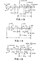
- the wire 17 from which it is wound is shown in Figure 4.
- the mandrel 18 on which the wire 17 is wound to form the coil 16 is shown in Figure 5.
- the wire 17 is formed of a suitable material such as stainless steel and has a length of approximately 7 feet and a diameter of .007 inches plus or minus .0002 inches. A major portion of the wire 17 has an outer dimension of .007 but the remainder of the wire is centerless ground to provide a decreasing diameter towards the distal extremity of the wire.
- a transition portion 17b of a suitable length such as 2.5 centimeters in which there is a dimension change from .007 inches to .005 inches for a length of approximately 60 centimeters from the distal extremity of the wire.
- a portion 17c of the wire has a diameter of .005 inches.
- another transition in diameter is made over a distance of approximately 2.5 centimeters from .005 inches to .003 inches.
- a portion 17e having a length of approximately 10 centimeters which has a diameter of .003 inches.
- the mandrel 18 on which the wire 17 is wound is shown in Figure 5 and is formed of a suitable material such as steel having a diameter of .019 inches extending over the portion 18a.
- a transition portion 18b is provided extending over 2 1/2 centimeters in which the diameter is decreased from .019 to .015 inches.
- Another portion 18c is provided having a diameter of .015 inches extending up to another transition portion 18d in which the diameter is decreased to .011 inches so that the distal extremity of the mandrel provided by the portion 18e has a diameter of .011 inches and a length of approximately 12.5 centimeters.
- the coil or coil section 16 is then formed by taking the wire 17 and taking the end of the smallest diameter and starting it on the mandrel at the point 21 and progressively winding the wire onto the mandrel 18 in a helix in a direction towards the larger diameter end over a distance of approximately 15.5 centimeters.
- the larger diameter wire begins in a region closer to the proximal end and the smaller diameter wire ends in a region closer to the distal end of the coil 16.
- the core or coil section 16 can be removed from the mandrel and trimmed to length.
- the proximal and distal ends of the coil 16 can be stretched apart slightly so that the ends can be screwed together with other coils or coil sections as hereinafter described.
- the coil section 23 which forms the tip of the guide wire 11 is formed of a suitable wire such as a platinum alloy having a diameter of .003 inches plus or minus .0002 inches. This wire 11 is 3 centimeters plus or minus one millimeter and having an outside diameter of approximately .018 inches maximum. The interior diameter corresponds to the diameter of the mandrel which is approximately .011 inches.
- One end of the coil 23 is stretched so as it make it possible to screw into another coil end as hereinafter described.
- the coil or coil section 16 after being wound or removed from the mandrel is formed so that it is provided with a portion 16a having an outside diameter of approximately .035 inches, another portion 16b having an outside diameter of approximately .027 inches and a distal extremity 16c having an outside diameter of approximately .018 inches.
- Another core or coil section 26 is provided which can be identified as the proximal coil.
- This coil is formed by winding a suitable material such as stainless steel wire having a diameter of .00.7 inches on the portion 18a of the mandrel 18 having a diameter of .019 inches.
- the coil 26 is then coated with a suitable plastic material such as Teflon and is cut to a suitable length, as for example, 81.5 centimeters with one centimeter of the same near the distal extremity being uncoated and stretched for a screw together brazed joint as hereinafter described.
- the guide wire 11 also includes a length of shrink tubing 31 having a suitable length as, for example, 45 centimeters as shown in Figure 9 and having an outside diameter of approximately .41 inches and an inside diameter of approximately .026 inches.
- the guide wire may now be assembled.
- the shrink tubing 31 is taken and is shrunk down onto the ground core element 12 approximately 100 centimeters from the distal tip of the core element 12. This can be accomplished in any suitable manner as, for example, by a batch process or by individual treatment of the shrink tubing with heat.
- the Teflon coated coil 26 is then placed on the core element 12 and bonded to the core element 12 at the point at which it is juxtaposed to the distal extremity of the shrink tubing 31 by the use of a suitable material such as Cyanoacrylate.
- the coil or coil section 16 is then positioned on the core element 12 and its proximal extremity is threaded into the distal extremity of the Teflon coated coil 26 and thereafter a brazed joint 33 is formed to bond the juxtaposed ends of the coil 16 to the coil 26.
- the screw together. joint 33 with the brazing is shown in Figure 2.
- a gold alloy 33 can be utilized to form the joint 33. The use of gold which is radiopaque permits the doctor to see where the .035 portion of the guide wire 11 starts by the use of a fluoroscope.
- the coil 16 when so positioned on the core element 12 has its larger diameter wire beginning in a region closer to the proximal end and its smaller diameter wire ending in a region closer to the distal end.
- the platinum coil 23 is then taken and its proximal extremity is positioned on the core element 12 and threaded into the distal extremity of the coil or coil section 16. After they have been screwed together, a suitable solder can be utilized for forming a joint 34 between the juxtaposed ends of the coils 23 and 16 and also to bond the same to the distal extremity of the core element 12. A tip 36 which has a rounded configuration is then provided on the distal extremity of the platinum coil 23.
- a torquer 38 of a conventional construction is mounted on the proximal extremity of the polyethylene shrink tubing 31.
- the torquer 38 firmly grasps the guide wire 11 and makes it possible for a physician by use of a hand to apply torque to the guide wire.
- the guide wire can have a suitable overall length as, for example, a length of 145 centimeters.
- the operation and use of the guide wire 11 is very similar to that for other guide wires. It, however, has numerous characteristics which are particularly adapted to particular types of operations as, for example, where it is desired to make deeper penetration into the kidney of the human body. It also has a very small diameter tip while still having a relatively large diameter proximal to the tip to facilitate tracking of the catheter under the fluoroscope.
- the tapering of the coils or coil sections is particularly important and is made possible by the use of a tapered wire which is utilized for forming the tapered coil or coil sections.
- the screw together joints between the coil sections provides for transitions between the coil sections while still providing a smooth exterior circumferential surface.
Abstract
Description
- This invention relates to guide wires for use with catheters and more particularly, to guide wires with an attenuated diameter and having torsional control.
- Guide wires heretofore have been provided, however, guide wires which make it possible to penetrate small blood vessels with adequate proximal strength for catheter tracking capabilities as, for example, in the kidney and which still permit high torsional capabilities have not been available.
- There is therefore a need for a torsional attenuating diameter guide wire.
- It would be desirable to provide a guide wire which has a progressively attenuated diameter and to provide a guide wire of the above character which has high torsional capabilities.
- It would further be desirable to provide a guide wire of the above character which is provided with a small tip facilitating deep penetration into small vessels and to provide a guide wire of the above character which has a relatively large proximal diameter to facilitate tracking of the catheter while it is in use.
- The present invention is further described by way of example only with reference to the accompanying drawings, in which:
- Figure 1 is a side elevational view of a torsional guide wire with a progressively attenuated diameter incorporating the present invention.
- Figure 2 is an enlarged view of the distal extremity of the guide wire shown in Figure 1.
- Figure 3 is a side elevational view of the core utilized in the guide wire shown in Figure 1.
- Figure 4 is a side elevational view of the wire utilized for making the tapered coil for the guide wire in Figure 1.
- Figure 5 is a side elevational view of the winding mandrel for the tapered coil of Figure 6.
- Figure 6 is a side elevational view of the tapered coil made from winding the wire of Figure 4 onto the mandrel of Figure 5.
- Figure 7 is a cross sectional view of the platinum coil tip utilized in the guide wire shown in Figure 1.
- Figure 8 is a cross sectional view of the proximal coil utilized in the guide wire shown in Figure 1.
- Figure 9 is a side elevational view of the plastic tubing utilized in the guide wire shown in Figure 1.
- In general, the torsional guide wire with a progressively attenuated diameter is comprised of an elongate core element having proximal and distal ends and having a decreasing cross sectional area in a direction towards the distal end. It is also comprised of a coil carried by and secured to the core element and extends over the distal extremity of the core element. The coil has proximal and distal ends and has a diameter which decreases in a direction towards the distal end. The coil is formed of wire which has a diameter which decreases from one end to the other end and is wound in a helix so that the larger diameter wire begins in a region closer to the proximal end and the smaller diameter wire ends in a region closer to the distal end.
- More in particular as shown in Figures 1 and 2 of the drawings, the attenuating diameter guide wire 11 consists of a
core element 12. Thecore element 12 is shown in detail in Figure 3 and is formed of a suitable material such as stainless steel and has a suitable diameter such as from .015 to .025 inch and preferably a diameter of .020 inch, plus or minus .0003 inch and having a suitable length such as 7 feet. The core element is provided with proximal anddistal ends core element 12 is centerless ground to provide a core wire which has a decreasing cross sectional area in a direction towards the distal end. Thus as shown, thecore element 12 is provided with a cylindrical portion 12a which extends over a major portion of the length of the core element. Atapered portion 12b adjoins the portion 12a and extends over a suitable distance such as 2 1/2 centimeters and provides a taper, for example, from .020 inches to .0145 to .0155 inches and preferably a dimension of .015 inches. The remaining length of the core element is centerless ground to a dimension such as .015 inches for a length of approximately 35 centimeters. Thereafter, in a further grinding operation a transition region 12d is provided which over a length of approximately 2.5 centimeters provides a transition from .015 to .009 to .010 inches. The followingportion 12e of approximately 10 centimeters is centerless ground to the .010 inch dimension. Thereafter an additionaltransitional region 12f is provided which provides a transition from .010 inches to .002 to .0025 inches. This transition extends over approximately 3 centimeters. The remaining distal extremity of the core wire as, for example, a length of approximately 2 centimeters is ground so that it has a diameter of .002 to .0025 inches. Thus it can be seen that a core element has been provided which has been carefully dimensioned by centerless grinding to provide a decreasing cross sectional area or a taper as hereinbefore described. - The guide wire 11 also consists of a
tapered coil 16. Thecoil 16 itself is shown in Figure 6. The wire 17 from which it is wound is shown in Figure 4. Themandrel 18 on which the wire 17 is wound to form thecoil 16 is shown in Figure 5. The wire 17 is formed of a suitable material such as stainless steel and has a length of approximately 7 feet and a diameter of .007 inches plus or minus .0002 inches. A major portion of the wire 17 has an outer dimension of .007 but the remainder of the wire is centerless ground to provide a decreasing diameter towards the distal extremity of the wire. Thus in addition to the cylindrical portion 17a there is provided atransition portion 17b of a suitable length such as 2.5 centimeters in which there is a dimension change from .007 inches to .005 inches for a length of approximately 60 centimeters from the distal extremity of the wire. Aportion 17c of the wire has a diameter of .005 inches. At another portion, 17d of the wire, another transition in diameter is made over a distance of approximately 2.5 centimeters from .005 inches to .003 inches. There is then provided aportion 17e having a length of approximately 10 centimeters which has a diameter of .003 inches. - The
mandrel 18 on which the wire 17 is wound is shown in Figure 5 and is formed of a suitable material such as steel having a diameter of .019 inches extending over the portion 18a. Atransition portion 18b is provided extending over 2 1/2 centimeters in which the diameter is decreased from .019 to .015 inches. Anotherportion 18c is provided having a diameter of .015 inches extending up to another transition portion 18d in which the diameter is decreased to .011 inches so that the distal extremity of the mandrel provided by theportion 18e has a diameter of .011 inches and a length of approximately 12.5 centimeters. - The coil or
coil section 16 is then formed by taking the wire 17 and taking the end of the smallest diameter and starting it on the mandrel at thepoint 21 and progressively winding the wire onto themandrel 18 in a helix in a direction towards the larger diameter end over a distance of approximately 15.5 centimeters. Thus, the larger diameter wire begins in a region closer to the proximal end and the smaller diameter wire ends in a region closer to the distal end of thecoil 16. After the winding has been completed, the core orcoil section 16 can be removed from the mandrel and trimmed to length. The proximal and distal ends of thecoil 16 can be stretched apart slightly so that the ends can be screwed together with other coils or coil sections as hereinafter described. - The
coil section 23 which forms the tip of the guide wire 11 is formed of a suitable wire such as a platinum alloy having a diameter of .003 inches plus or minus .0002 inches. This wire 11 is 3 centimeters plus or minus one millimeter and having an outside diameter of approximately .018 inches maximum. The interior diameter corresponds to the diameter of the mandrel which is approximately .011 inches. One end of thecoil 23 is stretched so as it make it possible to screw into another coil end as hereinafter described. - The coil or
coil section 16 after being wound or removed from the mandrel is formed so that it is provided with a portion 16a having an outside diameter of approximately .035 inches, anotherportion 16b having an outside diameter of approximately .027 inches and adistal extremity 16c having an outside diameter of approximately .018 inches. - Another core or
coil section 26 is provided which can be identified as the proximal coil. This coil is formed by winding a suitable material such as stainless steel wire having a diameter of .00.7 inches on the portion 18a of themandrel 18 having a diameter of .019 inches. Thecoil 26 is then coated with a suitable plastic material such as Teflon and is cut to a suitable length, as for example, 81.5 centimeters with one centimeter of the same near the distal extremity being uncoated and stretched for a screw together brazed joint as hereinafter described. - The guide wire 11 also includes a length of
shrink tubing 31 having a suitable length as, for example, 45 centimeters as shown in Figure 9 and having an outside diameter of approximately .41 inches and an inside diameter of approximately .026 inches. - With these fabricated components hereinbefore described, the guide wire may now be assembled. To start the assembly, the
shrink tubing 31 is taken and is shrunk down onto theground core element 12 approximately 100 centimeters from the distal tip of thecore element 12. This can be accomplished in any suitable manner as, for example, by a batch process or by individual treatment of the shrink tubing with heat. The Teflon coatedcoil 26 is then placed on thecore element 12 and bonded to thecore element 12 at the point at which it is juxtaposed to the distal extremity of theshrink tubing 31 by the use of a suitable material such as Cyanoacrylate. The coil orcoil section 16 is then positioned on thecore element 12 and its proximal extremity is threaded into the distal extremity of the Teflon coatedcoil 26 and thereafter abrazed joint 33 is formed to bond the juxtaposed ends of thecoil 16 to thecoil 26. The screw together.joint 33 with the brazing is shown in Figure 2. Agold alloy 33 can be utilized to form the joint 33. The use of gold which is radiopaque permits the doctor to see where the .035 portion of the guide wire 11 starts by the use of a fluoroscope. Thecoil 16 when so positioned on thecore element 12 has its larger diameter wire beginning in a region closer to the proximal end and its smaller diameter wire ending in a region closer to the distal end. - The
platinum coil 23 is then taken and its proximal extremity is positioned on thecore element 12 and threaded into the distal extremity of the coil orcoil section 16. After they have been screwed together, a suitable solder can be utilized for forming a joint 34 between the juxtaposed ends of thecoils core element 12. Atip 36 which has a rounded configuration is then provided on the distal extremity of theplatinum coil 23. - After these assembly operations been completed, a
torquer 38 of a conventional construction is mounted on the proximal extremity of the polyethylene shrinktubing 31. Thetorquer 38 firmly grasps the guide wire 11 and makes it possible for a physician by use of a hand to apply torque to the guide wire. The guide wire can have a suitable overall length as, for example, a length of 145 centimeters. - The operation and use of the guide wire 11 is very similar to that for other guide wires. It, however, has numerous characteristics which are particularly adapted to particular types of operations as, for example, where it is desired to make deeper penetration into the kidney of the human body. It also has a very small diameter tip while still having a relatively large diameter proximal to the tip to facilitate tracking of the catheter under the fluoroscope. The tapering of the coils or coil sections is particularly important and is made possible by the use of a tapered wire which is utilized for forming the tapered coil or coil sections. In addition, the screw together joints between the coil sections provides for transitions between the coil sections while still providing a smooth exterior circumferential surface.
- It is apparent from the foregoing that there has been provided a new and improved guide wire which has a progressively attenuated diameter and which has good torsional capabilities. It also has a construction which can be economically manufactured in quantity with great precision. Even though a tapered tip sub assembly has been provided in connection with a Teflon coated coil and polyethylene shrink tubing, there is a very smooth transition provided between the different materials utilized in the guide wire facilitating its use in connection with small vessels in humans.
Claims (9)
Applications Claiming Priority (2)
| Application Number | Priority Date | Filing Date | Title |
|---|---|---|---|
| US724624 | 1985-04-18 | ||
| US06/724,624 US4619274A (en) | 1985-04-18 | 1985-04-18 | Torsional guide wire with attenuated diameter |
Publications (2)
| Publication Number | Publication Date |
|---|---|
| EP0200430A1 true EP0200430A1 (en) | 1986-11-05 |
| EP0200430B1 EP0200430B1 (en) | 1990-04-04 |
Family
ID=24911176
Family Applications (1)
| Application Number | Title | Priority Date | Filing Date |
|---|---|---|---|
| EP86302895A Expired EP0200430B1 (en) | 1985-04-18 | 1986-04-17 | Torsional guide wire with attenuated diameter |
Country Status (5)
| Country | Link |
|---|---|
| US (1) | US4619274A (en) |
| EP (1) | EP0200430B1 (en) |
| JP (1) | JPH0611339B2 (en) |
| CA (1) | CA1265011A (en) |
| DE (1) | DE3670001D1 (en) |
Cited By (25)
| Publication number | Priority date | Publication date | Assignee | Title |
|---|---|---|---|---|
| GB2203650A (en) * | 1987-04-21 | 1988-10-26 | Cordis Corp | Catheter guidewire |
| WO1989006985A1 (en) * | 1988-01-27 | 1989-08-10 | Advanced Biomedical Devices, Inc. | Steerable guidewire for vascular system |
| CH674466A5 (en) * | 1988-02-03 | 1990-06-15 | Sterimed Gmbh | Guide wire for catheter with increased flexibility |
| EP0382974A1 (en) * | 1989-01-23 | 1990-08-22 | C.R. Bard, Inc. | Braided guide wire and method for the use thereof |
| EP0405823A2 (en) * | 1989-06-29 | 1991-01-02 | Cook Incorporated | Hydrophilically coated flexible wire guide |
| AU621098B2 (en) * | 1988-01-27 | 1992-03-05 | Advanced Biomedical Devices, Inc. | Steerable guidewire for vascular system |
| EP0523621A2 (en) * | 1991-07-18 | 1993-01-20 | Kabushiki Kaisha Kobe Seiko Sho | Catheter guide wire and catheter |
| EP2532300A3 (en) * | 2005-01-18 | 2013-01-16 | Acclarent, Inc. | Paranasal insertion device |
| US9603506B2 (en) | 2006-09-15 | 2017-03-28 | Acclarent, Inc. | Methods and devices for facilitating visualization in a surgical environment |
| US9610428B2 (en) | 2004-04-21 | 2017-04-04 | Acclarent, Inc. | Devices, systems and methods useable for treating frontal sinusitis |
| US9649477B2 (en) | 2004-04-21 | 2017-05-16 | Acclarent, Inc. | Frontal sinus spacer |
| US9814379B2 (en) | 2004-04-21 | 2017-11-14 | Acclarent, Inc. | Methods and apparatus for treating disorders of the ear nose and throat |
| US9820688B2 (en) | 2006-09-15 | 2017-11-21 | Acclarent, Inc. | Sinus illumination lightwire device |
| US9826999B2 (en) | 2004-04-21 | 2017-11-28 | Acclarent, Inc. | Methods and apparatus for treating disorders of the ear nose and throat |
| US10098652B2 (en) | 2004-04-21 | 2018-10-16 | Acclarent, Inc. | Systems and methods for transnasal dilation of passageways in the ear, nose or throat |
| US10124154B2 (en) | 2005-06-10 | 2018-11-13 | Acclarent, Inc. | Catheters with non-removable guide members useable for treatment of sinusitis |
| US10188413B1 (en) | 2004-04-21 | 2019-01-29 | Acclarent, Inc. | Deflectable guide catheters and related methods |
| US10492810B2 (en) | 2004-04-21 | 2019-12-03 | Acclarent, Inc. | Devices, systems and methods for diagnosing and treating sinusitis and other disorders of the ears, nose and/or throat |
| US10500380B2 (en) | 2004-04-21 | 2019-12-10 | Acclarent, Inc. | Devices, systems and methods useable for treating sinusitis |
| US10631756B2 (en) | 2004-04-21 | 2020-04-28 | Acclarent, Inc. | Guidewires for performing image guided procedures |
| US10856727B2 (en) | 2004-04-21 | 2020-12-08 | Acclarent, Inc. | Endoscopic methods and devices for transnasal procedures |
| US10874838B2 (en) | 2004-04-21 | 2020-12-29 | Acclarent, Inc. | Systems and methods for transnasal dilation of passageways in the ear, nose or throat |
| US11065061B2 (en) | 2004-04-21 | 2021-07-20 | Acclarent, Inc. | Systems and methods for performing image guided procedures within the ear, nose, throat and paranasal sinuses |
| US11202644B2 (en) | 2004-04-21 | 2021-12-21 | Acclarent, Inc. | Shapeable guide catheters and related methods |
| US11529502B2 (en) | 2004-04-21 | 2022-12-20 | Acclarent, Inc. | Apparatus and methods for dilating and modifying ostia of paranasal sinuses and other intranasal or paranasal structures |
Families Citing this family (183)
| Publication number | Priority date | Publication date | Assignee | Title |
|---|---|---|---|---|
| US4944740A (en) * | 1984-09-18 | 1990-07-31 | Medtronic Versaflex, Inc. | Outer exchange catheter system |
| JPS61162956A (en) * | 1985-01-11 | 1986-07-23 | 東レ株式会社 | Leak balloon catheter |
| US4917088A (en) * | 1985-05-02 | 1990-04-17 | C. R. Bard, Inc. | Balloon dilation probe |
| FR2584288A1 (en) * | 1985-07-08 | 1987-01-09 | Bazenet Jean Pierre | OESOPHAGIC PROBE TYPE INTRACORPOREAL PROBE AND DEVICE FOR MOUNTING BALLOONS OF SUCH A PROBE |
| US4724846A (en) * | 1986-01-10 | 1988-02-16 | Medrad, Inc. | Catheter guide wire assembly |
| US4721117A (en) * | 1986-04-25 | 1988-01-26 | Advanced Cardiovascular Systems, Inc. | Torsionally stabilized guide wire with outer jacket |
| USRE34695E (en) * | 1986-04-25 | 1994-08-16 | Advanced Cardiovascular Systems, Inc. | Torsionally stabilized guide wire with outer jacket |
| US4739768B2 (en) * | 1986-06-02 | 1995-10-24 | Target Therapeutics Inc | Catheter for guide-wire tracking |
| US4854330A (en) * | 1986-07-10 | 1989-08-08 | Medrad, Inc. | Formed core catheter guide wire assembly |
| US4723936A (en) * | 1986-07-22 | 1988-02-09 | Versaflex Delivery Systems Inc. | Steerable catheter |
| US5125895A (en) * | 1986-07-22 | 1992-06-30 | Medtronic Versaflex, Inc. | Steerable catheter |
| US4719924A (en) * | 1986-09-09 | 1988-01-19 | C. R. Bard, Inc. | Small diameter steerable guidewire with adjustable tip |
| US4763647A (en) * | 1987-01-06 | 1988-08-16 | C. R. Bard, Inc. | Dual coil steerable guidewire |
| US4815478A (en) * | 1987-02-17 | 1989-03-28 | Medtronic Versaflex, Inc. | Steerable guidewire with deflectable tip |
| US4757827A (en) * | 1987-02-17 | 1988-07-19 | Versaflex Delivery Systems Inc. | Steerable guidewire with deflectable tip |
| US4813434A (en) * | 1987-02-17 | 1989-03-21 | Medtronic Versaflex, Inc. | Steerable guidewire with deflectable tip |
| US4793351A (en) * | 1987-06-15 | 1988-12-27 | Mansfield Scientific, Inc. | Multi-lumen balloon catheter |
| US4808164A (en) * | 1987-08-24 | 1989-02-28 | Progressive Angioplasty Systems, Inc. | Catheter for balloon angioplasty |
| US4927413A (en) * | 1987-08-24 | 1990-05-22 | Progressive Angioplasty Systems, Inc. | Catheter for balloon angioplasty |
| US4846193A (en) * | 1987-09-21 | 1989-07-11 | Advanced Cardiovascular Systems, Inc. | Extendable guide wire for vascular procedures |
| US4934380A (en) * | 1987-11-27 | 1990-06-19 | Boston Scientific Corporation | Medical guidewire |
| US4830023A (en) * | 1987-11-27 | 1989-05-16 | Medi-Tech, Incorporated | Medical guidewire |
| US4846186A (en) * | 1988-01-12 | 1989-07-11 | Cordis Corporation | Flexible guidewire |
| US4895168A (en) * | 1988-01-21 | 1990-01-23 | Schneider (Usa) Inc., A Pfizer Company | Guidewire with movable core and external tubular safety cover |
| US4884579A (en) * | 1988-04-18 | 1989-12-05 | Target Therapeutics | Catheter guide wire |
| US5067489A (en) * | 1988-08-16 | 1991-11-26 | Flexmedics Corporation | Flexible guide with safety tip |
| US4984581A (en) * | 1988-10-12 | 1991-01-15 | Flexmedics Corporation | Flexible guide having two-way shape memory alloy |
| US4957117A (en) * | 1988-11-03 | 1990-09-18 | Ramsey Foundation | One-handed percutaneous transluminal angioplasty steering device and method |
| US5001825A (en) * | 1988-11-03 | 1991-03-26 | Cordis Corporation | Catheter guidewire fabrication method |
| US4986279A (en) * | 1989-03-01 | 1991-01-22 | National-Standard Company | Localization needle assembly with reinforced needle assembly |
| US4922924A (en) * | 1989-04-27 | 1990-05-08 | C. R. Bard, Inc. | Catheter guidewire with varying radiopacity |
| US5063935A (en) * | 1989-04-27 | 1991-11-12 | C. R. Bard, Inc. | Catheter guidewire with varying radiopacity |
| US5042985A (en) * | 1989-05-11 | 1991-08-27 | Advanced Cardiovascular Systems, Inc. | Dilatation catheter suitable for peripheral arteries |
| DE59010156D1 (en) * | 1989-06-01 | 1996-04-04 | Schneider Europ Ag | Catheter arrangement with a guide wire and method for producing such a guide wire |
| US4991602A (en) * | 1989-06-27 | 1991-02-12 | Flexmedics Corporation | Flexible guide wire with safety tip |
| US5111829A (en) * | 1989-06-28 | 1992-05-12 | Boston Scientific Corporation | Steerable highly elongated guidewire |
| AU740244B2 (en) * | 1989-06-29 | 2001-11-01 | Cook Incorporated | Hydrophilically coated flexible wire guide |
| US4976690A (en) * | 1989-08-10 | 1990-12-11 | Scimed Life Systems, Inc. | Variable stiffness angioplasty catheter |
| US5144959A (en) * | 1989-08-15 | 1992-09-08 | C. R. Bard, Inc. | Catheter guidewire with varying radiopacity |
| USRE41029E1 (en) | 1990-03-13 | 2009-12-01 | The Regents Of The University Of California | Endovascular electrolytically detachable wire and tip for the formation of thrombus in arteries, veins, aneurysms, vascular malformations and arteriovenous fistulas |
| USRE42625E1 (en) | 1990-03-13 | 2011-08-16 | The Regents Of The University Of California | Endovascular electrolytically detachable wire and tip for the formation of thrombus in arteries, veins, aneurysms, vascular malformations and arteriovenous fistulas |
| US6083220A (en) | 1990-03-13 | 2000-07-04 | The Regents Of The University Of California | Endovascular electrolytically detachable wire and tip for the formation of thrombus in arteries, veins, aneurysms, vascular malformations and arteriovenous fistulas |
| US5851206A (en) * | 1990-03-13 | 1998-12-22 | The Regents Of The University Of California | Method and apparatus for endovascular thermal thrombosis and thermal cancer treatment |
| US5095915A (en) * | 1990-03-19 | 1992-03-17 | Target Therapeutics | Guidewire with flexible distal tip |
| US5054501A (en) * | 1990-05-16 | 1991-10-08 | Brigham & Women's Hospital | Steerable guide wire for cannulation of tubular or vascular organs |
| US5147317A (en) * | 1990-06-04 | 1992-09-15 | C.R. Bard, Inc. | Low friction varied radiopacity guidewire |
| CA2095814C (en) * | 1990-11-09 | 2002-09-17 | John E. Abele | Guidewire for crossing occlusions in blood vessels |
| US6501551B1 (en) | 1991-04-29 | 2002-12-31 | Massachusetts Institute Of Technology | Fiber optic imaging endoscope interferometer with at least one faraday rotator |
| US6134003A (en) * | 1991-04-29 | 2000-10-17 | Massachusetts Institute Of Technology | Method and apparatus for performing optical measurements using a fiber optic imaging guidewire, catheter or endoscope |
| US6485413B1 (en) | 1991-04-29 | 2002-11-26 | The General Hospital Corporation | Methods and apparatus for forward-directed optical scanning instruments |
| US6111645A (en) | 1991-04-29 | 2000-08-29 | Massachusetts Institute Of Technology | Grating based phase control optical delay line |
| CA2068584C (en) * | 1991-06-18 | 1997-04-22 | Paul H. Burmeister | Intravascular guide wire and method for manufacture thereof |
| US5325746A (en) * | 1991-09-27 | 1994-07-05 | Cook Incorporated | Wire guide control handle |
| US5243996A (en) * | 1992-01-03 | 1993-09-14 | Cook, Incorporated | Small-diameter superelastic wire guide |
| US5413560A (en) * | 1992-03-30 | 1995-05-09 | Pameda N.V. | Method of rapid catheter exchange |
| CA2091921C (en) * | 1992-03-30 | 1999-06-01 | Ronald J. Solar | Inflatable catheter system |
| US5395331A (en) * | 1992-04-27 | 1995-03-07 | Minnesota Mining And Manufacturing Company | Retrograde coronary sinus catheter having a ribbed balloon |
| US5327891A (en) * | 1992-07-30 | 1994-07-12 | Rammler David H | Catheter track and catheter for diagnosis and treatment |
| USRE37117E1 (en) | 1992-09-22 | 2001-03-27 | Target Therapeutics, Inc. | Detachable embolic coil assembly using interlocking clasps and method of use |
| US5315747A (en) * | 1992-10-30 | 1994-05-31 | Pameda N.V. | Method of preparing a balloon dilatation catheter |
| US5531690A (en) * | 1992-10-30 | 1996-07-02 | Cordis Corporation | Rapid exchange catheter |
| US5383467A (en) * | 1992-11-18 | 1995-01-24 | Spectrascience, Inc. | Guidewire catheter and apparatus for diagnostic imaging |
| AU5672194A (en) * | 1992-11-18 | 1994-06-22 | Spectrascience, Inc. | Apparatus for diagnostic imaging |
| US5360406A (en) * | 1992-11-19 | 1994-11-01 | Minnesota Mining And Manufacturing Company | Stylet for retrograde coronary sinus cannula |
| US5341817A (en) * | 1992-12-14 | 1994-08-30 | Cordis Corporation | Elongated guidewire for use in dilation procedures |
| US5377690A (en) * | 1993-02-09 | 1995-01-03 | C. R. Bard, Inc. | Guidewire with round forming wire |
| US5365943A (en) * | 1993-03-12 | 1994-11-22 | C. R. Bard, Inc. | Anatomically matched steerable PTCA guidewire |
| US5322508A (en) * | 1993-04-08 | 1994-06-21 | Cordis Corporation | Guidewire fluid delivery system and method of use |
| US5800453A (en) * | 1993-04-19 | 1998-09-01 | Target Therapeutics, Inc. | Detachable embolic coil assembly using interlocking hooks and slots |
| US5925059A (en) * | 1993-04-19 | 1999-07-20 | Target Therapeutics, Inc. | Detachable embolic coil assembly |
| US5769796A (en) * | 1993-05-11 | 1998-06-23 | Target Therapeutics, Inc. | Super-elastic composite guidewire |
| US5772609A (en) * | 1993-05-11 | 1998-06-30 | Target Therapeutics, Inc. | Guidewire with variable flexibility due to polymeric coatings |
| US5409015A (en) * | 1993-05-11 | 1995-04-25 | Target Therapeutics, Inc. | Deformable tip super elastic guidewire |
| US7883474B1 (en) * | 1993-05-11 | 2011-02-08 | Target Therapeutics, Inc. | Composite braided guidewire |
| US5749837A (en) * | 1993-05-11 | 1998-05-12 | Target Therapeutics, Inc. | Enhanced lubricity guidewire |
| US5402799A (en) * | 1993-06-29 | 1995-04-04 | Cordis Corporation | Guidewire having flexible floppy tip |
| US5465733A (en) * | 1993-10-14 | 1995-11-14 | Hinohara; Tomoaki | Guide wire for catheters and method for its use |
| US5507301A (en) * | 1993-11-19 | 1996-04-16 | Advanced Cardiovascular Systems, Inc. | Catheter and guidewire system with flexible distal portions |
| US6673025B1 (en) | 1993-12-01 | 2004-01-06 | Advanced Cardiovascular Systems, Inc. | Polymer coated guidewire |
| US5488959A (en) * | 1993-12-27 | 1996-02-06 | Cordis Corporation | Medical guidewire and welding process |
| US5606981A (en) * | 1994-03-11 | 1997-03-04 | C. R. Bard, Inc. | Catheter guidewire with radiopaque markers |
| US5458605A (en) * | 1994-04-04 | 1995-10-17 | Advanced Cardiovascular Systems, Inc. | Coiled reinforced retractable sleeve for stent delivery catheter |
| US6139510A (en) * | 1994-05-11 | 2000-10-31 | Target Therapeutics Inc. | Super elastic alloy guidewire |
| US5498250A (en) * | 1994-05-18 | 1996-03-12 | Scimed Life Systems, Inc. | Catheter guide wire with multiple radiopacity |
| US5497783A (en) * | 1994-05-18 | 1996-03-12 | Scimed Life Systems, Inc. | Guidewire having radioscopic tip |
| US5673707A (en) * | 1994-09-23 | 1997-10-07 | Boston Scientific Corporation | Enhanced performance guidewire |
| US5554114A (en) * | 1994-10-20 | 1996-09-10 | Micro Therapeutics, Inc. | Infusion device with preformed shape |
| US5664580A (en) * | 1995-01-31 | 1997-09-09 | Microvena Corporation | Guidewire having bimetallic coil |
| US5797876A (en) * | 1995-11-27 | 1998-08-25 | Therox, Inc. | High pressure perfusion device |
| US6488637B1 (en) | 1996-04-30 | 2002-12-03 | Target Therapeutics, Inc. | Composite endovascular guidewire |
| US5827201A (en) * | 1996-07-26 | 1998-10-27 | Target Therapeutics, Inc. | Micro-braided guidewire |
| US5916166A (en) * | 1996-11-19 | 1999-06-29 | Interventional Technologies, Inc. | Medical guidewire with fully hardened core |
| WO1998033443A1 (en) | 1997-02-03 | 1998-08-06 | Angioguard, Inc. | Vascular filter |
| US5876356A (en) * | 1997-04-02 | 1999-03-02 | Cordis Corporation | Superelastic guidewire with a shapeable tip |
| US6019777A (en) | 1997-04-21 | 2000-02-01 | Advanced Cardiovascular Systems, Inc. | Catheter and method for a stent delivery system |
| US7455646B2 (en) * | 1997-06-04 | 2008-11-25 | Advanced Cardiovascular Systems, Inc. | Polymer coated guide wire |
| US7494474B2 (en) | 1997-06-04 | 2009-02-24 | Advanced Cardiovascular Systems, Inc. | Polymer coated guidewire |
| US6132388A (en) | 1997-10-16 | 2000-10-17 | Scimed Life Systems, Inc. | Guide wire tip |
| US6306105B1 (en) * | 1998-05-14 | 2001-10-23 | Scimed Life Systems, Inc. | High performance coil wire |
| US6340368B1 (en) | 1998-10-23 | 2002-01-22 | Medtronic Inc. | Implantable device with radiopaque ends |
| JP2002531234A (en) * | 1998-12-10 | 2002-09-24 | マイクロ・セラピューティクス・インコーポレーテッド | Improved guidewire |
| US6361557B1 (en) | 1999-02-05 | 2002-03-26 | Medtronic Ave, Inc. | Staplebutton radiopaque marker |
| US20020138094A1 (en) * | 1999-02-12 | 2002-09-26 | Thomas Borillo | Vascular filter system |
| US6991641B2 (en) * | 1999-02-12 | 2006-01-31 | Cordis Corporation | Low profile vascular filter system |
| DE69917213T2 (en) | 1999-03-29 | 2005-07-28 | William Cook Europe Aps | A guidewire |
| ATE305324T1 (en) | 1999-03-29 | 2005-10-15 | William Cook Europe As | A GUIDE WIRE |
| US6146339A (en) * | 1999-05-24 | 2000-11-14 | Advanced Cardiovascular Systems | Guide wire with operator controllable tip stiffness |
| US7229462B2 (en) * | 1999-07-30 | 2007-06-12 | Angioguard, Inc. | Vascular filter system for carotid endarterectomy |
| US7229463B2 (en) * | 1999-07-30 | 2007-06-12 | Angioguard, Inc. | Vascular filter system for cardiopulmonary bypass |
| US6445939B1 (en) | 1999-08-09 | 2002-09-03 | Lightlab Imaging, Llc | Ultra-small optical probes, imaging optics, and methods for using same |
| JP3426174B2 (en) | 1999-12-24 | 2003-07-14 | 朝日インテック株式会社 | Medical guidewire |
| US20040082879A1 (en) * | 2000-01-28 | 2004-04-29 | Klint Henrik S. | Endovascular medical device with plurality of wires |
| WO2001054761A2 (en) | 2000-01-28 | 2001-08-02 | William Cook, Europe Aps | Endovascular medical device with plurality of wires |
| EP1195174B1 (en) * | 2000-10-03 | 2005-01-26 | William Cook Europe ApS | A guide wire |
| US6527732B1 (en) | 2000-10-17 | 2003-03-04 | Micro Therapeutics, Inc. | Torsionally compensated guidewire |
| US6669652B2 (en) | 2000-12-21 | 2003-12-30 | Advanced Cardiovascular Systems, Inc. | Guidewire with tapered distal coil |
| US6428552B1 (en) * | 2001-01-22 | 2002-08-06 | Lumend, Inc. | Method and apparatus for crossing intravascular occlusions |
| US8721625B2 (en) | 2001-01-26 | 2014-05-13 | Cook Medical Technologies Llc | Endovascular medical device with plurality of wires |
| US6579302B2 (en) | 2001-03-06 | 2003-06-17 | Cordis Corporation | Total occlusion guidewire device |
| US6428559B1 (en) | 2001-04-03 | 2002-08-06 | Cordis Corporation | Removable, variable-diameter vascular filter system |
| US7532920B1 (en) * | 2001-05-31 | 2009-05-12 | Advanced Cardiovascular Systems, Inc. | Guidewire with optical fiber |
| US7329223B1 (en) * | 2001-05-31 | 2008-02-12 | Abbott Cardiovascular Systems Inc. | Catheter with optical fiber sensor |
| US6596011B2 (en) * | 2001-06-12 | 2003-07-22 | Cordis Corporation | Emboli extraction catheter and vascular filter system |
| US6656203B2 (en) | 2001-07-18 | 2003-12-02 | Cordis Corporation | Integral vascular filter system |
| US6908448B2 (en) * | 2001-08-24 | 2005-06-21 | Dermisonics, Inc. | Substance delivery device |
| US20030060843A1 (en) | 2001-09-27 | 2003-03-27 | Don Boucher | Vascular filter system with encapsulated filter |
| US20030074040A1 (en) * | 2001-10-16 | 2003-04-17 | Florio Joseph J. | System, device and method for placing a body implantable lead in the coronary sinus region of the heart |
| US6958074B2 (en) | 2002-01-07 | 2005-10-25 | Cordis Corporation | Releasable and retrievable vascular filter system |
| US7063707B2 (en) | 2002-03-06 | 2006-06-20 | Scimed Life Systems, Inc. | Medical retrieval device |
| WO2004011076A2 (en) * | 2002-07-25 | 2004-02-05 | Boston Scientific Limited | Medical device for navigation through anatomy and method of making same |
| US7044921B2 (en) * | 2003-02-03 | 2006-05-16 | Scimed Life Systems, Inc | Medical device with changeable tip flexibility |
| US8591540B2 (en) | 2003-02-27 | 2013-11-26 | Abbott Cardiovascular Systems Inc. | Embolic filtering devices |
| JP4186689B2 (en) * | 2003-04-18 | 2008-11-26 | ニプロ株式会社 | Guide wire |
| US7803395B2 (en) | 2003-05-15 | 2010-09-28 | Biomerix Corporation | Reticulated elastomeric matrices, their manufacture and use in implantable devices |
| US7540845B2 (en) | 2003-09-05 | 2009-06-02 | Boston Scientific Scimed, Inc | Medical device coil |
| US7833175B2 (en) * | 2003-09-05 | 2010-11-16 | Boston Scientific Scimed, Inc. | Medical device coil |
| US20050197683A1 (en) * | 2003-09-24 | 2005-09-08 | Levatino Samuel R. | Microtubes for surgery and dentistry |
| US6997713B2 (en) * | 2003-09-24 | 2006-02-14 | Levatino Samuel R | Microtubes for surgery and dentistry |
| US20040107283A1 (en) * | 2003-10-06 | 2004-06-03 | Trilibis Inc. | System and method for the aggregation and matching of personal information |
| US7237313B2 (en) * | 2003-12-05 | 2007-07-03 | Boston Scientific Scimed, Inc. | Elongated medical device for intracorporal use |
| US7763077B2 (en) | 2003-12-24 | 2010-07-27 | Biomerix Corporation | Repair of spinal annular defects and annulo-nucleoplasty regeneration |
| US7462175B2 (en) | 2004-04-21 | 2008-12-09 | Acclarent, Inc. | Devices, systems and methods for treating disorders of the ear, nose and throat |
| US9089258B2 (en) | 2004-04-21 | 2015-07-28 | Acclarent, Inc. | Endoscopic methods and devices for transnasal procedures |
| US9101384B2 (en) | 2004-04-21 | 2015-08-11 | Acclarent, Inc. | Devices, systems and methods for diagnosing and treating sinusitis and other disorders of the ears, Nose and/or throat |
| US8864787B2 (en) | 2004-04-21 | 2014-10-21 | Acclarent, Inc. | Ethmoidotomy system and implantable spacer devices having therapeutic substance delivery capability for treatment of paranasal sinusitis |
| US7419497B2 (en) | 2004-04-21 | 2008-09-02 | Acclarent, Inc. | Methods for treating ethmoid disease |
| US9351750B2 (en) | 2004-04-21 | 2016-05-31 | Acclarent, Inc. | Devices and methods for treating maxillary sinus disease |
| US9554691B2 (en) | 2004-04-21 | 2017-01-31 | Acclarent, Inc. | Endoscopic methods and devices for transnasal procedures |
| US20060004323A1 (en) | 2004-04-21 | 2006-01-05 | Exploramed Nc1, Inc. | Apparatus and methods for dilating and modifying ostia of paranasal sinuses and other intranasal or paranasal structures |
| US20100030251A1 (en) * | 2006-05-24 | 2010-02-04 | Mayo Foundation For Medical Education And Research | Devices and methods for crossing chronic total occlusions |
| JP4829684B2 (en) * | 2006-06-02 | 2011-12-07 | 株式会社エフエムディ | Medical guidewire |
| US8485199B2 (en) | 2007-05-08 | 2013-07-16 | Acclarent, Inc. | Methods and devices for protecting nasal turbinate during surgery |
| JP5631744B2 (en) | 2008-02-05 | 2014-11-26 | ブリッジポイント、メディカル、インコーポレイテッドBridgepoint Medical, Inc. | Crossing occluded parts in blood vessels |
| US8337425B2 (en) | 2008-02-05 | 2012-12-25 | Bridgepoint Medical, Inc. | Endovascular device with a tissue piercing distal probe and associated methods |
| US20090299171A1 (en) * | 2008-06-03 | 2009-12-03 | Medtronic Vascular, Inc. | Intraluminal Access and Imaging Device |
| US20100049167A1 (en) * | 2008-08-20 | 2010-02-25 | Cook Incorporated | Introducer sheath having reinforced distal taper |
| US8444577B2 (en) | 2009-01-05 | 2013-05-21 | Cook Medical Technologies Llc | Medical guide wire |
| US7942917B2 (en) * | 2009-04-17 | 2011-05-17 | Medtronic Vascular, Inc. | Hollow helical stent system |
| US20100269830A1 (en) * | 2009-04-24 | 2010-10-28 | Sage Products, Inc. | Fluid Removing Apparatus for Respiratory Tract |
| JP5408727B2 (en) * | 2010-03-19 | 2014-02-05 | 日本ライフライン株式会社 | Medical guidewire |
| US9017246B2 (en) | 2010-11-19 | 2015-04-28 | Boston Scientific Scimed, Inc. | Biliary catheter systems including stabilizing members |
| JP2012187263A (en) * | 2011-03-10 | 2012-10-04 | Sumitomo Bakelite Co Ltd | Medical device and method for producing the same |
| US20130110000A1 (en) * | 2011-10-31 | 2013-05-02 | Terumo Medical Corporation | Dual Diameter Introducer Guide Wire |
| JP2014233592A (en) * | 2013-06-05 | 2014-12-15 | 朝日インテック株式会社 | Pusher guide wire |
| US10285830B2 (en) | 2014-12-05 | 2019-05-14 | Stryker Corporation | Method of manufacturing implants |
| JP6768224B2 (en) * | 2015-02-27 | 2020-10-14 | ニプロ株式会社 | Guide wire |
| CN113350655B (en) | 2016-02-24 | 2024-03-19 | 禾木(中国)生物工程有限公司 | Nerve vascular catheter with enhanced flexibility |
| US10391274B2 (en) | 2016-07-07 | 2019-08-27 | Brian Giles | Medical device with distal torque control |
| US9918705B2 (en) | 2016-07-07 | 2018-03-20 | Brian Giles | Medical devices with distal control |
| CN110381855B (en) | 2017-01-06 | 2023-07-04 | 因赛普特有限责任公司 | Antithrombotic coating for aneurysm treatment devices |
| US11849929B2 (en) | 2018-03-01 | 2023-12-26 | Beijing Bywave Sensing Technology Co., Ltd. | Pressure guide wire |
| US11395665B2 (en) | 2018-05-01 | 2022-07-26 | Incept, Llc | Devices and methods for removing obstructive material, from an intravascular site |
| JP2021522885A (en) | 2018-05-01 | 2021-09-02 | インセプト・リミテッド・ライアビリティ・カンパニーIncept,Llc | Devices and methods for removing obstructive substances from intravascular sites |
| US11471582B2 (en) | 2018-07-06 | 2022-10-18 | Incept, Llc | Vacuum transfer tool for extendable catheter |
| US11517335B2 (en) | 2018-07-06 | 2022-12-06 | Incept, Llc | Sealed neurovascular extendable catheter |
| US11452533B2 (en) | 2019-01-10 | 2022-09-27 | Abbott Cardiovascular Systems Inc. | Guide wire tip having roughened surface |
| US11766539B2 (en) | 2019-03-29 | 2023-09-26 | Incept, Llc | Enhanced flexibility neurovascular catheter |
| US11134859B2 (en) | 2019-10-15 | 2021-10-05 | Imperative Care, Inc. | Systems and methods for multivariate stroke detection |
| CA3162704A1 (en) | 2019-12-18 | 2021-06-24 | Imperative Care, Inc. | Methods and systems for treating venous thromboembolic disease |
| US11553935B2 (en) | 2019-12-18 | 2023-01-17 | Imperative Care, Inc. | Sterile field clot capture module for use in thrombectomy system |
| US11439799B2 (en) | 2019-12-18 | 2022-09-13 | Imperative Care, Inc. | Split dilator aspiration system |
| EP4117762A1 (en) | 2020-03-10 | 2023-01-18 | Imperative Care, Inc. | Enhanced flexibility neurovascular catheter |
| US11207497B1 (en) | 2020-08-11 | 2021-12-28 | Imperative Care, Inc. | Catheter with enhanced tensile strength |
Citations (4)
| Publication number | Priority date | Publication date | Assignee | Title |
|---|---|---|---|---|
| DE522204C (en) * | 1931-04-01 | Maurycy Lubelski Dr | Special for the expansion of constrictions in the feeding pipe | |
| US3789841A (en) * | 1971-09-15 | 1974-02-05 | Becton Dickinson Co | Disposable guide wire |
| US4020829A (en) * | 1975-10-23 | 1977-05-03 | Willson James K V | Spring guide wire with torque control for catheterization of blood vessels and method of using same |
| EP0141006A1 (en) * | 1983-09-16 | 1985-05-15 | Terumo Kabushiki Kaisha | Guide wire for catheter |
Family Cites Families (3)
| Publication number | Priority date | Publication date | Assignee | Title |
|---|---|---|---|---|
| JPS5935705B2 (en) * | 1982-07-19 | 1984-08-30 | 旭大隈産業株式会社 | Continuous feeding method of wire rod for heading machine |
| JPS5916649U (en) * | 1982-07-23 | 1984-02-01 | ハナコ・メディカル株式会社 | Improvement of lead wire for super selective angiography |
| US4554929A (en) * | 1983-07-13 | 1985-11-26 | Advanced Cardiovascular Systems, Inc. | Catheter guide wire with short spring tip and method of using the same |
-
1985
- 1985-04-18 US US06/724,624 patent/US4619274A/en not_active Expired - Lifetime
-
1986
- 1986-04-17 EP EP86302895A patent/EP0200430B1/en not_active Expired
- 1986-04-17 DE DE8686302895T patent/DE3670001D1/en not_active Expired - Lifetime
- 1986-04-17 CA CA000506946A patent/CA1265011A/en not_active Expired
- 1986-04-18 JP JP61089855A patent/JPH0611339B2/en not_active Expired - Fee Related
Patent Citations (4)
| Publication number | Priority date | Publication date | Assignee | Title |
|---|---|---|---|---|
| DE522204C (en) * | 1931-04-01 | Maurycy Lubelski Dr | Special for the expansion of constrictions in the feeding pipe | |
| US3789841A (en) * | 1971-09-15 | 1974-02-05 | Becton Dickinson Co | Disposable guide wire |
| US4020829A (en) * | 1975-10-23 | 1977-05-03 | Willson James K V | Spring guide wire with torque control for catheterization of blood vessels and method of using same |
| EP0141006A1 (en) * | 1983-09-16 | 1985-05-15 | Terumo Kabushiki Kaisha | Guide wire for catheter |
Cited By (42)
| Publication number | Priority date | Publication date | Assignee | Title |
|---|---|---|---|---|
| GB2203650A (en) * | 1987-04-21 | 1988-10-26 | Cordis Corp | Catheter guidewire |
| US4811743A (en) * | 1987-04-21 | 1989-03-14 | Cordis Corporation | Catheter guidewire |
| GB2203650B (en) * | 1987-04-21 | 1991-04-03 | Cordis Corp | Catheter guidewire. |
| WO1989006985A1 (en) * | 1988-01-27 | 1989-08-10 | Advanced Biomedical Devices, Inc. | Steerable guidewire for vascular system |
| AU621098B2 (en) * | 1988-01-27 | 1992-03-05 | Advanced Biomedical Devices, Inc. | Steerable guidewire for vascular system |
| CH674466A5 (en) * | 1988-02-03 | 1990-06-15 | Sterimed Gmbh | Guide wire for catheter with increased flexibility |
| EP0382974A1 (en) * | 1989-01-23 | 1990-08-22 | C.R. Bard, Inc. | Braided guide wire and method for the use thereof |
| EP0405823A2 (en) * | 1989-06-29 | 1991-01-02 | Cook Incorporated | Hydrophilically coated flexible wire guide |
| EP0405823A3 (en) * | 1989-06-29 | 1991-02-06 | Cook Incorporated | Hydrophilically coated flexible wire guide |
| EP0523621A2 (en) * | 1991-07-18 | 1993-01-20 | Kabushiki Kaisha Kobe Seiko Sho | Catheter guide wire and catheter |
| EP0523621A3 (en) * | 1991-07-18 | 1993-04-14 | Kabushiki Kaisha Kobe Seiko Sho | Catheter guide wire and catheter |
| US5306252A (en) * | 1991-07-18 | 1994-04-26 | Kabushiki Kaisha Kobe Seiko Sho | Catheter guide wire and catheter |
| US10098652B2 (en) | 2004-04-21 | 2018-10-16 | Acclarent, Inc. | Systems and methods for transnasal dilation of passageways in the ear, nose or throat |
| US11020136B2 (en) | 2004-04-21 | 2021-06-01 | Acclarent, Inc. | Deflectable guide catheters and related methods |
| US9610428B2 (en) | 2004-04-21 | 2017-04-04 | Acclarent, Inc. | Devices, systems and methods useable for treating frontal sinusitis |
| US9649477B2 (en) | 2004-04-21 | 2017-05-16 | Acclarent, Inc. | Frontal sinus spacer |
| US9814379B2 (en) | 2004-04-21 | 2017-11-14 | Acclarent, Inc. | Methods and apparatus for treating disorders of the ear nose and throat |
| US11957318B2 (en) | 2004-04-21 | 2024-04-16 | Acclarent, Inc. | Methods and apparatus for treating disorders of the ear nose and throat |
| US9826999B2 (en) | 2004-04-21 | 2017-11-28 | Acclarent, Inc. | Methods and apparatus for treating disorders of the ear nose and throat |
| US10034682B2 (en) | 2004-04-21 | 2018-07-31 | Acclarent, Inc. | Devices, systems and methods useable for treating frontal sinusitis |
| US11864725B2 (en) | 2004-04-21 | 2024-01-09 | Acclarent, Inc. | Devices, systems and methods for diagnosing and treating sinusitis and other disorders of the ears, nose and/or throat |
| US11529502B2 (en) | 2004-04-21 | 2022-12-20 | Acclarent, Inc. | Apparatus and methods for dilating and modifying ostia of paranasal sinuses and other intranasal or paranasal structures |
| US10188413B1 (en) | 2004-04-21 | 2019-01-29 | Acclarent, Inc. | Deflectable guide catheters and related methods |
| US10441758B2 (en) | 2004-04-21 | 2019-10-15 | Acclarent, Inc. | Frontal sinus spacer |
| US10492810B2 (en) | 2004-04-21 | 2019-12-03 | Acclarent, Inc. | Devices, systems and methods for diagnosing and treating sinusitis and other disorders of the ears, nose and/or throat |
| US10500380B2 (en) | 2004-04-21 | 2019-12-10 | Acclarent, Inc. | Devices, systems and methods useable for treating sinusitis |
| US10631756B2 (en) | 2004-04-21 | 2020-04-28 | Acclarent, Inc. | Guidewires for performing image guided procedures |
| US10695080B2 (en) | 2004-04-21 | 2020-06-30 | Acclarent, Inc. | Devices, systems and methods for diagnosing and treating sinusitis and other disorders of the ears, nose and/or throat |
| US11511090B2 (en) | 2004-04-21 | 2022-11-29 | Acclarent, Inc. | Devices, systems and methods useable for treating sinusitis |
| US10779752B2 (en) | 2004-04-21 | 2020-09-22 | Acclarent, Inc. | Guidewires for performing image guided procedures |
| US10806477B2 (en) | 2004-04-21 | 2020-10-20 | Acclarent, Inc. | Systems and methods for transnasal dilation of passageways in the ear, nose or throat |
| US11202644B2 (en) | 2004-04-21 | 2021-12-21 | Acclarent, Inc. | Shapeable guide catheters and related methods |
| US10856727B2 (en) | 2004-04-21 | 2020-12-08 | Acclarent, Inc. | Endoscopic methods and devices for transnasal procedures |
| US10874838B2 (en) | 2004-04-21 | 2020-12-29 | Acclarent, Inc. | Systems and methods for transnasal dilation of passageways in the ear, nose or throat |
| US11065061B2 (en) | 2004-04-21 | 2021-07-20 | Acclarent, Inc. | Systems and methods for performing image guided procedures within the ear, nose, throat and paranasal sinuses |
| US11019989B2 (en) | 2004-04-21 | 2021-06-01 | Acclarent, Inc. | Methods and apparatus for treating disorders of the ear nose and throat |
| EP2532300A3 (en) * | 2005-01-18 | 2013-01-16 | Acclarent, Inc. | Paranasal insertion device |
| US10842978B2 (en) | 2005-06-10 | 2020-11-24 | Acclarent, Inc. | Catheters with non-removable guide members useable for treatment of sinusitis |
| US10124154B2 (en) | 2005-06-10 | 2018-11-13 | Acclarent, Inc. | Catheters with non-removable guide members useable for treatment of sinusitis |
| US9603506B2 (en) | 2006-09-15 | 2017-03-28 | Acclarent, Inc. | Methods and devices for facilitating visualization in a surgical environment |
| US10716629B2 (en) | 2006-09-15 | 2020-07-21 | Acclarent, Inc. | Methods and devices for facilitating visualization in a surgical environment |
| US9820688B2 (en) | 2006-09-15 | 2017-11-21 | Acclarent, Inc. | Sinus illumination lightwire device |
Also Published As
| Publication number | Publication date |
|---|---|
| JPS62363A (en) | 1987-01-06 |
| US4619274A (en) | 1986-10-28 |
| EP0200430B1 (en) | 1990-04-04 |
| CA1265011A (en) | 1990-01-30 |
| JPH0611339B2 (en) | 1994-02-16 |
| DE3670001D1 (en) | 1990-05-10 |
Similar Documents
| Publication | Publication Date | Title |
|---|---|---|
| US4619274A (en) | Torsional guide wire with attenuated diameter | |
| US5065769A (en) | Small diameter guidewires of multi-filar, cross-wound coils | |
| JP3403887B2 (en) | Guide wire | |
| CA1224104A (en) | Guide wire for catheters | |
| US4813434A (en) | Steerable guidewire with deflectable tip | |
| US4815478A (en) | Steerable guidewire with deflectable tip | |
| JP2737650B2 (en) | Guide wire | |
| US4757827A (en) | Steerable guidewire with deflectable tip | |
| US5313967A (en) | Helical guidewire | |
| US5069217A (en) | Steerable guide wire | |
| US5213111A (en) | Composite wire guide construction | |
| US5228453A (en) | Catheter guide wire | |
| US4721117A (en) | Torsionally stabilized guide wire with outer jacket | |
| US5916166A (en) | Medical guidewire with fully hardened core | |
| US6132388A (en) | Guide wire tip | |
| US4554929A (en) | Catheter guide wire with short spring tip and method of using the same | |
| US4867173A (en) | Steerable guidewire | |
| US8915865B2 (en) | Medical device for navigation through anatomy and method of making same | |
| US5376083A (en) | Steerable infusion guide wire | |
| US5129890A (en) | Hydrophilically coated flexible wire guide | |
| US6383146B1 (en) | Guidewire | |
| USRE34695E (en) | Torsionally stabilized guide wire with outer jacket | |
| EP0812599A2 (en) | Catheter guide wire | |
| EP0435961A1 (en) | Small diameter guidewires | |
| AU740244B2 (en) | Hydrophilically coated flexible wire guide |
Legal Events
| Date | Code | Title | Description |
|---|---|---|---|
| PUAI | Public reference made under article 153(3) epc to a published international application that has entered the european phase |
Free format text: ORIGINAL CODE: 0009012 |
|
| AK | Designated contracting states |
Kind code of ref document: A1 Designated state(s): CH DE FR GB LI |
|
| 17P | Request for examination filed |
Effective date: 19870421 |
|
| 17Q | First examination report despatched |
Effective date: 19880725 |
|
| GRAA | (expected) grant |
Free format text: ORIGINAL CODE: 0009210 |
|
| AK | Designated contracting states |
Kind code of ref document: B1 Designated state(s): CH DE FR GB LI |
|
| REF | Corresponds to: |
Ref document number: 3670001 Country of ref document: DE Date of ref document: 19900510 |
|
| ET | Fr: translation filed | ||
| PLBE | No opposition filed within time limit |
Free format text: ORIGINAL CODE: 0009261 |
|
| STAA | Information on the status of an ep patent application or granted ep patent |
Free format text: STATUS: NO OPPOSITION FILED WITHIN TIME LIMIT |
|
| 26N | No opposition filed | ||
| PGFP | Annual fee paid to national office [announced via postgrant information from national office to epo] |
Ref country code: CH Payment date: 20010621 Year of fee payment: 16 |
|
| REG | Reference to a national code |
Ref country code: GB Ref legal event code: IF02 |
|
| PGFP | Annual fee paid to national office [announced via postgrant information from national office to epo] |
Ref country code: FR Payment date: 20020401 Year of fee payment: 17 |
|
| PGFP | Annual fee paid to national office [announced via postgrant information from national office to epo] |
Ref country code: GB Payment date: 20020416 Year of fee payment: 17 |
|
| PGFP | Annual fee paid to national office [announced via postgrant information from national office to epo] |
Ref country code: DE Payment date: 20020418 Year of fee payment: 17 |
|
| PG25 | Lapsed in a contracting state [announced via postgrant information from national office to epo] |
Ref country code: LI Free format text: LAPSE BECAUSE OF NON-PAYMENT OF DUE FEES Effective date: 20020430 Ref country code: CH Free format text: LAPSE BECAUSE OF NON-PAYMENT OF DUE FEES Effective date: 20020430 |
|
| REG | Reference to a national code |
Ref country code: CH Ref legal event code: PL |
|
| PG25 | Lapsed in a contracting state [announced via postgrant information from national office to epo] |
Ref country code: GB Free format text: LAPSE BECAUSE OF NON-PAYMENT OF DUE FEES Effective date: 20030417 |
|
| PG25 | Lapsed in a contracting state [announced via postgrant information from national office to epo] |
Ref country code: DE Free format text: LAPSE BECAUSE OF NON-PAYMENT OF DUE FEES Effective date: 20031101 |
|
| GBPC | Gb: european patent ceased through non-payment of renewal fee |
Effective date: 20030417 |
|
| PG25 | Lapsed in a contracting state [announced via postgrant information from national office to epo] |
Ref country code: FR Free format text: LAPSE BECAUSE OF NON-PAYMENT OF DUE FEES Effective date: 20031231 |
|
| REG | Reference to a national code |
Ref country code: FR Ref legal event code: ST |