EP0201038B2 - Secondary battery using non-aqueous solvent - Google Patents
Secondary battery using non-aqueous solvent Download PDFInfo
- Publication number
- EP0201038B2 EP0201038B2 EP86105951A EP86105951A EP0201038B2 EP 0201038 B2 EP0201038 B2 EP 0201038B2 EP 86105951 A EP86105951 A EP 86105951A EP 86105951 A EP86105951 A EP 86105951A EP 0201038 B2 EP0201038 B2 EP 0201038B2
- Authority
- EP
- European Patent Office
- Prior art keywords
- secondary battery
- aqueous solvent
- negative electrode
- carbonaceous material
- solvent according
- Prior art date
- Legal status (The legal status is an assumption and is not a legal conclusion. Google has not performed a legal analysis and makes no representation as to the accuracy of the status listed.)
- Expired - Lifetime
Links
Images


Classifications
-
- H—ELECTRICITY
- H01—ELECTRIC ELEMENTS
- H01M—PROCESSES OR MEANS, e.g. BATTERIES, FOR THE DIRECT CONVERSION OF CHEMICAL ENERGY INTO ELECTRICAL ENERGY
- H01M4/00—Electrodes
- H01M4/02—Electrodes composed of, or comprising, active material
- H01M4/36—Selection of substances as active materials, active masses, active liquids
- H01M4/58—Selection of substances as active materials, active masses, active liquids of inorganic compounds other than oxides or hydroxides, e.g. sulfides, selenides, tellurides, halogenides or LiCoFy; of polyanionic structures, e.g. phosphates, silicates or borates
- H01M4/583—Carbonaceous material, e.g. graphite-intercalation compounds or CFx
-
- H—ELECTRICITY
- H01—ELECTRIC ELEMENTS
- H01M—PROCESSES OR MEANS, e.g. BATTERIES, FOR THE DIRECT CONVERSION OF CHEMICAL ENERGY INTO ELECTRICAL ENERGY
- H01M10/00—Secondary cells; Manufacture thereof
- H01M10/05—Accumulators with non-aqueous electrolyte
- H01M10/052—Li-accumulators
- H01M10/0525—Rocking-chair batteries, i.e. batteries with lithium insertion or intercalation in both electrodes; Lithium-ion batteries
-
- H—ELECTRICITY
- H01—ELECTRIC ELEMENTS
- H01M—PROCESSES OR MEANS, e.g. BATTERIES, FOR THE DIRECT CONVERSION OF CHEMICAL ENERGY INTO ELECTRICAL ENERGY
- H01M4/00—Electrodes
- H01M4/02—Electrodes composed of, or comprising, active material
- H01M4/36—Selection of substances as active materials, active masses, active liquids
- H01M4/58—Selection of substances as active materials, active masses, active liquids of inorganic compounds other than oxides or hydroxides, e.g. sulfides, selenides, tellurides, halogenides or LiCoFy; of polyanionic structures, e.g. phosphates, silicates or borates
- H01M4/583—Carbonaceous material, e.g. graphite-intercalation compounds or CFx
- H01M4/587—Carbonaceous material, e.g. graphite-intercalation compounds or CFx for inserting or intercalating light metals
-
- Y—GENERAL TAGGING OF NEW TECHNOLOGICAL DEVELOPMENTS; GENERAL TAGGING OF CROSS-SECTIONAL TECHNOLOGIES SPANNING OVER SEVERAL SECTIONS OF THE IPC; TECHNICAL SUBJECTS COVERED BY FORMER USPC CROSS-REFERENCE ART COLLECTIONS [XRACs] AND DIGESTS
- Y02—TECHNOLOGIES OR APPLICATIONS FOR MITIGATION OR ADAPTATION AGAINST CLIMATE CHANGE
- Y02E—REDUCTION OF GREENHOUSE GAS [GHG] EMISSIONS, RELATED TO ENERGY GENERATION, TRANSMISSION OR DISTRIBUTION
- Y02E60/00—Enabling technologies; Technologies with a potential or indirect contribution to GHG emissions mitigation
- Y02E60/10—Energy storage using batteries
Definitions
- the present invention relates to a secondary battery using a non-aqueous solvent, more particularly to a secondary battery using a non-aqueous solvent which is less in self-discharge, has good charge/discharge cycle characteristics and is excellent in storability.
- a negative electrode comprising a polyacetylene and a lithium ion are combined as disclosed in Japanese Provisional Patent Publication No. 136469/1981.
- a conductive polymer which is usable for a negative electrode material there may be mentioned, in addition to the above polyacetylene, a linear high molecular compound having a conjugated double bond such as a poly(p-phenylene), a polypyrrol, a polythienylene, a polyaniline, a poly(p-phenylenesulfide), a poly(p-phenyleneoxide) and the like.
- these conductive polymers are lightweight and a potential for doping/undoping an alkali metal ion such as lithium ion, etc. to said polymer is substantially similar as a charge/discharge potential in case that the alkali metal is employed as a negative electrode, it has an advantage that an energy density per unit weight is high when it has been used in a secondary battery.
- the aforesaid conductive polymer is unstable at a state of doping the alkali metal ion, that is, a charged state, and since it reacts with a solvent or decomposes itself, there are problems that a self-discharge becomes remarkably great at well as a cycle characteristic will be deteriorated.
- a secondary battery in which as the carbonaceous material for constituting a negative electrode, those obtained by carbonizing an organic high molecular compound such as a phenol resin, a polyacrylonitrile, a cellulose and the like have been used.
- a secondary battery using as a negative electrode a carbonaceous material obtained by heat treating an aromatic condensed polymer, which has an atomic ratio of hydrogen/carbon being in the range of 0.15 to 0.33 has been disclosed.
- Such a secondary battery has high output power as compared with a secondary battery using the conventional conductive polymer or a graphite as a negative electrode.
- the negative electrode reacts with an electrolytic solvent of self-discharge and a deterioration of cycle characteristics will be caused.
- An object of the present invention is to eliminate such conventional problems and to provide a secondary battery using a non-aqueous solvent which is less in self-discharge, good in charge/discharge cycle characteristics and excellent in storability.
- the present inventors have carried out earnest investigations in order to establish the above object by focusing the development of a negative electrode material for the secondary battery using a non-aqueous solvent. As results, they have found that by constituting a negative electrode with a carbonaceous material which satisfies various conditions mentioned below simultaneously, a secondary battery using a non-aqueous solvent having excellent characterstics can be obtained and accomplished the present invention.
- the present invention provides a secondary battery according to the present claim 1.
- Fig. 1 is a longitudinal sectional view showing one example of the non-aqueous solvent secondary battery of the present invention.
- Figs. 2 to 4 are drawings showing charge/discharge curve of the batteries.
- a starting material for obtaining a carbonaceous material which constitutes a negative electrode it can be used at least one compound selected from the group consisting of a high molecular weight linear novolac resin, a condensed polycyclic hydrocarbon compound and polycyclic heterocyclic compound.
- Condensed polycyclic hydrocarbon compounds are such that at least two monocyclic hydrocarbon compounds consisting of a three-or more membered ring are condensed together or derivatives of such condensed products.
- Specific examples of the condensed polycyclic hydrocarbon compounds may be mentioned, for example, naphthalene, phenanthrene, anthracene, triphenylene, pyrene, chresene, naphthacene, picene, perylene, pentaphene, pentacene and the like, and the derivatives thereof may include carboxylic acid, carbocyclic acid anhydride or carboxylic acid amide of the above compunds.
- various kinds of pitches mainly comprising mixtures of the above respective compunds.
- Polycyclic heterocyclic compounds are such that at least two monocyclic heterocyclic compounds consisting of a three- or more membered ring are condensed together or at least one such monocyclic heterocyclic compound is condensed with at least one monocyclic hydrocarbon compound consisting of a three- or more membered ring and derivatives of such condensed products.
- polycyclic heterocyclic compounds may be mentioned, for example, indole, isoindole, quinoline, isoquinoline, quinoxaline, phthalazine, carbazole, acridine, phenazine, phenanthridine and the like, and the derivatives thereof may include carboxylic acid, carbocyclic acid anhydride or carboxylic acid amide of the above compounds. Further, 1,2,4,5-tetracarboxylic acid of benzene, its dianhydride or its diimide may also be used.
- the carbonaceous materials of the present invention are those obtained by carbonizing the above mentioned respective compound and have a pseudographite structure satisfying the following conditions simultaneously.
- an atomic ratio of hydrogen/carbon measured by an elemental analysis is not more than 0.10, more preferably not more than 0.07.
- a spacing (d002) of (002) plane measured by X-ray wide angle diffraction is 3.37 ⁇ or more, preferably 3.39 ⁇ to 3.68 ⁇ , more preferably 3.41 ⁇ to 3.68 ⁇ .
- a crystallite size in the direction of c axis, Lc, measured by the same X-ray wide angle diffraction is 12 ⁇ to 150 ⁇ , preferably 12 ⁇ to 100 ⁇ , more preferably 12 ⁇ to 70 ⁇ .
- the carbonaceous material of the present invention can be obtained by carbonizing the above-mentioned respective compounds, the procedures of the carbonization are considered as described below in the case of the condensed polycyclic hydrocarbon compound as the starting material. That is, when a thermal energy greater than the dissociation energy necessary to break the bond between the skeletal carbon and an adjacent hydrogen atom or a substituent is provided by heating, carbon radicals are formed predominantly by homolytic cleavage. A chain of carbon radicals is cyclized to provide a higher molecular weight and the polycyclic aromatic planes are developed so that the process of carbonization successively occurs.
- benzene rings are bound together one-dimensionally to form a one-dimensional graphite structure. Subsequently, the benzene rings start to bind with one another two-dimensionally, and gradually expanding polycyclic aromatic planes begin to stack in layers to form a two-dimensional graphite structure.
- the pseudographite structure in accordance with the present invention can be determined quantitatively by using an X-ray wide angle diffraction.
- a one-dimensional graphite formed in the initial stage of carbonization of the present invention shows no diffraction peak corresponding to the (002) plane or shows a very broad and its intensity is low.
- the polycyclic aromatic planes is developed two-dimensionally to some extent and begin to stack one after another, the diffraction peak corresponding to the (002) plane gradually becomes sharp and its intensity increases.
- the pseudographite structure which characterizes the carbonaceous material of the present invention is such that the spacing of (002) planes, d002, is at least 3.37 ⁇ and the crystallite size in the direction of c axis, Lc, is not more than 150 ⁇ .
- d002 is at least 3.40 ⁇ and not more than 3.68 ⁇
- Lc is at least 12 ⁇ and not more than 150 ⁇ .
- the case where no diffraction peak corresponding to the (002) plane is observed at all is also included in the present invention.
- the carbonaceous material to be used is not satisfied any one of the above three inevitable requirements, that is, the atomic ratio of hydrogen/carbon is 0.10 or more, the spacing d002 of the (002) plane measured by the X-ray wide angle diffraction is not more than 3.37 ⁇ or the crystallite size in the direction of c axis, Lc, measured by the same exceeds 150 ⁇ , in the secondary battery using the carbonaceous material as the negative electrode, disadvantages that over voltage of charge/discharge at the negative electrode side becomes large, a gas is generated from the electrode at the charging, storability of the battery at the charged state is bad and charge/discharge cycle characteristics are deteriorated are caused.
- a crystallite size in the direction of a axis La is 10 ⁇ or more, more preferably 15 ⁇ or more and 70 ⁇ or less, particularly preferably 19 ⁇ or more.
- At least one of the signals have an inter-peak line width ( ⁇ Hpp) obtained by first differential absorption curve of the electron spin resonance spectrum (measured at 23°C) of preferably 20 gauss or more, or no signals have an inter-peak line width ( ⁇ Hpp) of not more than 20 gauss (20 ⁇ 10 ⁇ 4 Tesla). More preferably, at least one of the signals have an inter-peak line width ( ⁇ Hpp) obtained by first differential absorption curve of the electron spin resonance spectrum (measured at 23°C) of preferably 50 gauss (50 ⁇ 10 ⁇ 4 Tesla) or more, or no signals have an inter-peak line width ( ⁇ Hpp) of not more than 50 gauss (50 ⁇ 10 ⁇ 4 Tesla).
- the above carbonaceous material is specified by the atomic ratio of hydrogen/carbon obtained by the elemental analysis, but a small proportion of other atoms such as a nitrogen, oxygen, halogen may be present.
- the carbonaceous material constituting the negative electrode can be obtained by carbonating the aforesaid compounds, more specifically by sintering under vacuum or through an inert gas (N2, Ar, etc.). Since the carbonating temperature is closely related to the above atomic ratio of hydrogen/carbon, it is required to set the atomic ratio to not more than 0.10. The carbonating temperature is different depending on the kinds of the compounds to be used as a starting material but usually 500 to 3,000°C is preferred.
- the obtained carbonaceous material may be activated by heating the carbonaceous material under oxidative gaseous atmosphere such as vapor, carbon dioxide, etc. whereby a specific surface area thereof can be increased.
- oxidative gaseous atmosphere such as vapor, carbon dioxide, etc.
- the positive electrode material of the non-aqueous solvent secondary battery in accordance with the present invention is a metallic chalcogen compound which release or capture an alkali metal cation such as lithium ion, etc. accompanying charge/discharge reaction.
- metallic chalcogen compounds to be used as the constituting material of the positive electrode of the present invention may include oxides such as Cr3O8, V2O5, V6O13, LiCoO2, MoO3, WO3, etc.; sulfides such as TiS2, V2S5, MoS2, MoS3, CuS, Fe 0.25 V 0.75 S2, Cr 0.25 V 0.75 S2, Cr 0.5 V 0.5 S2, Na 0.1 CrS2, etc.; phosphine ⁇ sulfur compounds such as NiPS3, FePS3, etc.; and selenium compounds such as VSe2, NbSe3, etc., among them, TiS2, M,oS2 and V2O5 are particularly preferred.
- oxides such as Cr3O8, V2O5, V6O13, LiCoO2, MoO3, WO3, etc.
- sulfides such as TiS2, V2S5, MoS2, MoS3, CuS, Fe 0.25 V 0.75 S2, Cr 0.25 V 0.75 S2, Cr 0.5 V 0.5 S2, Na 0.1 CrS
- non-aqueous secondary battery of the present invention as the electrolyte, those dissolved an electrolytic salt in a non-aqueous solvent can be used.
- a non-aqueous solvent there may be used propylene carbonate, ethylene carbonate, dimethoxyethane, ⁇ -butyrolactone, tetrahydrofuran, 2-methyltetrahydrofuran, sulforane, 1,3-dioxorane and the like, and they may be used alone or in combination of 2 or more.
- electrolytic salts those obtained by optionally combining an anion such as CIO 4 - , PF 6 - , BF 4 - , CF3SO 3 - , AsF 6 - , etc. and an alkali metal cation such as Li+, Na+, K+, etc. can be used.
- an alkali metal cation such as Li+, Na+, K+, etc.
- cation species of quaternary amines such as N(CH3) 4 + , N(C2H5) 4 + , N(n-C3H7) 4 + , etc. may be used.
- either one of the positive electrode and the negative electrode or both of the positive and negative electrodes may preferably be doped an alkali metal cation such as Li+ and the like.
- a battery in the discharged state can be realized while doping in the negative electrode provides a battery in the charged state.
- doping is carried but in both of the positive and negative electrodes, a battery in any state between discharged and charged by changing the ratio of doping amounts to the respective electrodes can be manufactured.
- the capacity of the battery is determined by the total amounts of an alkali metal to be doped in the positive and/or negative electrodes.
- the alkali metal is doped in a film-like or a strip-like carbonaceous material or is doped in moldings prepared by mixing a powder of the carbonaceous material and a powder state adhesive such as polytetrafluoroethylene, polyethylene, etc. and kneading, and then by molding under heating.
- a powder state adhesive such as polytetrafluoroethylene, polyethylene, etc. and kneading
- the electrochemical method As the method for doping the alkali metal cation in the electrodes previously, there may be mentioned, for example, the electrochemical method, the chemical method and the physical method.
- the electrochemical method there may include a method in which the carbonaceous material of the present invention is used as the positive electrode, an alkali metal M is used as the negative electrode and an electrolyte obtained by dissolving an alkali metal salt such as MCIO4, MPF6, MBF4, MAsF6, MAICI4, MCI, MBr, Ml and the like (where M is anyone of Li, Na, K, Rb and Cs) in an organic solvent such as propylene carbonate, 1,2-dimethoxyethane, ⁇ -butyrolactone, dioxolan, ethylene carbonate, 2-methyltetrahydrofuran and the like is interposed between the electrodes to continue therebetween or a current is passed therethrough.
- an alkali metal salt such as MCIO4, MPF6, MBF4, MAsF6, MAICI4, MCI, MBr, Ml and the like (where M is anyone of Li, Na, K, Rb and Cs) in an organic solvent such as propylene carbonate, 1,2-dimeth
- the chemical method there may be mentioned the method in which the carbonaceous material according to the present invention is dipped in an organic solvent solution such as ether, aliphatic hydrocarbon, etc., dissolved an alkylated alkali metal therein.
- an organic solvent solution such as ether, aliphatic hydrocarbon, etc.
- an alkylated alkali metal therein.
- the physical method there may be mentioned the method in which the carbonaceous material according to the present invention is exposed to vapor of an alkali metal.
- the same method as in the above carbonaceous material can also be applied.
- the metallic chalcogen compound electrode when used as the positive electrode, a negative potential is applied to the electrode and a positive potential is applied to the opposite electrode.
- the opposite electrode material there may be mentioned, for example, an inert metal such as platinum, etc., and an alkali metal such as lithium, etc., but the use of lithium is particularly desired.
- the positive electrode and the negative electrode are laminated opposite to each other lying a separator between them and/or interposed a separator between them and a non-aqueous solvent containing an electrolyte.
- Each electrode has a plate-like structure in general, but the structure where one electrode is made a cylindrical shape and the other electrode is inserted therein may be employed. Further, the structure where the positive electrode and the negative electrode are made opposite to each other through a separator and spirally wound to form a spiral structure may also be employed.
- the electrolytic solution is impregnated in a separator such as a non woven, a woven, an open cell cellular foaming material and a porous plastic sheet and the separator is interposed between both of the electrodes.
- a separator such as a non woven, a woven, an open cell cellular foaming material and a porous plastic sheet and the separator is interposed between both of the electrodes.
- the non-aqueous secondary battery constituted by the negative electrolyt, the positive electrode and the electrode comprising the aforesaid each materials it is confirmed that an electrochemically oxidation/ reducton reaction in accordance with the dope/undope of the alkali metal ion is occurred at the charge/discharge and the battery has been less self-discharge and has good cycle characteristics.
- a discharging capacity of the positive electrode should preferably be set 1.1-fold or more to that of the negative electrode, more preferably 1.1-fold to 3-fold, and most preferably 1.5-fold to 2-fold.
- the capacity of the positive electrode is set 1.1-fold or more to that of the negative electrode to enlarge a space (residual capacity) capable of accepting a lithium ion at discharging.
- the capacity of the positive electrode When the capacity of the positive electrode is set 1.1-fold or more to that of the negative electrode, the capacity of the battery is regulated by the capacity of the negative electrode. Therefore, it is not preferred to remarkably enlarge the capacity of the positive electrode to that of the negative electrode since high capacity characteristics which are possessed of the battery of the present constitution will be lost, and thus, the discharging capacity of the positive electrode is set within the above range.
- each measurements of the elemental analysis, X-ray wide angle diffraction and electron spin resonance spectrum are carried out following the methods as described below.
- a sample is dried in vacuum at 120°C for about 15 hours. Then, the sample is transferred onto a hot plate in a dry box and dried in vacuum at 100°C for 1 hour. A portion of the dried sample is put into an aluminum cup in an argon atmosphere, and the carbon content is determined from the weight of CO2 gas evolved as a result of combustion whereas the hydrogen content is determined from the weight of H2O also evolved by combustion.
- an elemental analyzer of Perkin-Elmer Model 240 C was used.
- a powder of carbonaceous material (flaky carbonaceous material is reduced to a powder in an agate mortar) is packed into a sample cell together with about 15 wt% of the powder of an internal standard substance, a high-purity silicon powder of the standard grade for X-ray analysis.
- a wide-angle X-ray reflection diffractometer scan is obtained with monochromatic CuK ⁇ radiation from a graphite monochrometer. Instead of making corrections associated with the Lorentz factor, polarization factor, absorption factor and atomic scattering factor, the following simple and convenient method is used. Draw a baseline for the scan curves corresponding to diffractions at (002) and (110) Planes.
- K 0.90 is used.
- ⁇ , ⁇ and ⁇ ' the same as the previous paragraph.
- the first differential of the absorption spectrum of electron spin resonance was measured with JEOL JES-FE 1X ESR spectrometer in the X-band.
- a powder of carbonaceous material (flaky carbonaceous material is reduced to a powder in an agate mortar) is put into a capillary tube (ID: 1 mm) which is placed in an ESR tube (OD: 5 mm).
- the radiofrequency magnetic field is modulated by an amount of 6.3 gauss. All the procedures above are followed within air at 23°C.
- the value of the line width between peaks in the first differential of the absorption spectrum ( ⁇ Hpp) is determined by comparison to a standard sample Mn+/MgO.
- the thus obtained heat-treated mixture was not dissolved in ethanol but swelled.
- the swelled heat-treated mixture was carried out the press forming at a temperature of 190°C under a pressure of 200 Kg/cm to obtain a strip having a width of 2 cm, a length of 5 cm and a thickness of 1 mm.
- the positive electrode 5 is one in which is carried out a preliminary discharging at 2 mA for 10 hours in a propylene carbonate solution containing 1.5 mole/liter of LiCO4. Further, the positive electrode 5 is compressedly adhered to a collector 6 for the positive electrode comprising titanium which serves as a positive terminal. Betwen the negative electrode 1 and the positive electrode 5, a separator 7 comprising non woven fabric of propylene carbonate is provided therethrough and they are all compressedly adhered with each other by the spring 3.
- Reference numerals 8 and 9 are vessels made of Teflon (trade name, produced by du Pont de Nemours), and inner materials are sealed by an O ring 10. Moreover, 2 ml of a propylene carbonate solution containing 1.5 mole/liter of LiCIO4 as an electrolyte is filled in the separator 7, and the vessels 8 and 9.
Description
- The present invention relates to a secondary battery using a non-aqueous solvent, more particularly to a secondary battery using a non-aqueous solvent which is less in self-discharge, has good charge/discharge cycle characteristics and is excellent in storability.
- In recent years, as secondary batteries which are compact and lightweight and have high energy densities, those which use a kind of a conductive polymer as a negative electrode material and the negative electrode is combined with an electrolyte having dissolved an alkali metal ion such as lithium ion, sodium ion and the like have been attracted attention. This kind of secondary battery is doping/undoping or intercalating/deintercalating the aforesaid metal ion electrochemically to the negative electrode and this doping/undoping phenomenon, etc. are utilized as a charge/discharge step. Thus, it has an advantage that, as caused in the secondary battery which is employed a conventional alkaline metal itself as the negative electrode, internal short due to precipitation of the alkaline metal dendritely during the discharge or remarkable deterioration of charge/discharge efficiency can be eliminated.
- As this kind of secondary battery, there has been known one, for example, in which a negative electrode comprising a polyacetylene and a lithium ion are combined as disclosed in Japanese Provisional Patent Publication No. 136469/1981. Further, as a conductive polymer which is usable for a negative electrode material, there may be mentioned, in addition to the above polyacetylene, a linear high molecular compound having a conjugated double bond such as a poly(p-phenylene), a polypyrrol, a polythienylene, a polyaniline, a poly(p-phenylenesulfide), a poly(p-phenyleneoxide) and the like.
- Since these conductive polymers are lightweight and a potential for doping/undoping an alkali metal ion such as lithium ion, etc. to said polymer is substantially similar as a charge/discharge potential in case that the alkali metal is employed as a negative electrode, it has an advantage that an energy density per unit weight is high when it has been used in a secondary battery. However, the aforesaid conductive polymer is unstable at a state of doping the alkali metal ion, that is, a charged state, and since it reacts with a solvent or decomposes itself, there are problems that a self-discharge becomes remarkably great at well as a cycle characteristic will be deteriorated.
- On the other hand, there has been reported a secondary battery in which a graphite having a structure of spreading conjugated double bonds quadratically is used as a carbonaceous material and a graphite interlayer compound which is intercalated by electrochemically reducing an alkali metal ion is employed as a negative electrode active substance. However, in such a secondary battery, since an alkali metal-graphite interlayer compound formed by charging is chemically unstable and it reacts with solvent in accordance with destruction of a graphite structure, there are disadvantages that its storability is bad and deterioration of charge/discharge efficiency as well as lowering of cycle characteristics will be occurred.
- Further, there has been reported a secondary battery in which as the carbonaceous material for constituting a negative electrode, those obtained by carbonizing an organic high molecular compound such as a phenol resin, a polyacrylonitrile, a cellulose and the like have been used. For example, in Japanese Provisional Patent Publication No. 209864/1983, a secondary battery using as a negative electrode a carbonaceous material obtained by heat treating an aromatic condensed polymer, which has an atomic ratio of hydrogen/carbon being in the range of 0.15 to 0.33 has been disclosed.
- Such a secondary battery has high output power as compared with a secondary battery using the conventional conductive polymer or a graphite as a negative electrode. However, it is the actual circumstances that there is not yet improved at all in the point that the negative electrode reacts with an electrolytic solvent of self-discharge and a deterioration of cycle characteristics will be caused.
- As stated above, there remains a problem that a negative electrode material which utilizes a dope/undope or an intercalate/deintercalate phenomenon of an alkali metal ion is used in a battery, in all cases, a self-discharge increases and a cycle lifetime is short.
- An object of the present invention is to eliminate such conventional problems and to provide a secondary battery using a non-aqueous solvent which is less in self-discharge, good in charge/discharge cycle characteristics and excellent in storability.
- The present inventors have carried out earnest investigations in order to establish the above object by focusing the development of a negative electrode material for the secondary battery using a non-aqueous solvent. As results, they have found that by constituting a negative electrode with a carbonaceous material which satisfies various conditions mentioned below simultaneously, a secondary battery using a non-aqueous solvent having excellent characterstics can be obtained and accomplished the present invention.
- The present invention provides a secondary battery according to the present claim 1.
- Fig. 1 is a longitudinal sectional view showing one example of the non-aqueous solvent secondary battery of the present invention; and
- Figs. 2 to 4 are drawings showing charge/discharge curve of the batteries.
- In the secondary battery using a non-aqueous solvent of the present invention, as a starting material for obtaining a carbonaceous material which constitutes a negative electrode, it can be used at least one compound selected from the group consisting of a high molecular weight linear novolac resin, a condensed polycyclic hydrocarbon compound and polycyclic heterocyclic compound.
- Condensed polycyclic hydrocarbon compounds are such that at least two monocyclic hydrocarbon compounds consisting of a three-or more membered ring are condensed together or derivatives of such condensed products. Specific examples of the condensed polycyclic hydrocarbon compounds may be mentioned, for example, naphthalene, phenanthrene, anthracene, triphenylene, pyrene, chresene, naphthacene, picene, perylene, pentaphene, pentacene and the like, and the derivatives thereof may include carboxylic acid, carbocyclic acid anhydride or carboxylic acid amide of the above compunds. Further, various kinds of pitches mainly comprising mixtures of the above respective compunds.
- Polycyclic heterocyclic compounds are such that at least two monocyclic heterocyclic compounds consisting of a three- or more membered ring are condensed together or at least one such monocyclic heterocyclic compound is condensed with at least one monocyclic hydrocarbon compound consisting of a three- or more membered ring and derivatives of such condensed products. Specific examples of the polycyclic heterocyclic compounds may be mentioned, for example, indole, isoindole, quinoline, isoquinoline, quinoxaline, phthalazine, carbazole, acridine, phenazine, phenanthridine and the like, and the derivatives thereof may include carboxylic acid, carbocyclic acid anhydride or carboxylic acid amide of the above compounds. Further, 1,2,4,5-tetracarboxylic acid of benzene, its dianhydride or its diimide may also be used.
- The carbonaceous materials of the present invention are those obtained by carbonizing the above mentioned respective compound and have a pseudographite structure satisfying the following conditions simultaneously.
- That is, in the first place, an atomic ratio of hydrogen/carbon measured by an elemental analysis is not more than 0.10, more preferably not more than 0.07.
- In the second place, a spacing (d₀₀₂) of (002) plane measured by X-ray wide angle diffraction is 3.37 Å or more, preferably 3.39 Å to 3.68 Å, more preferably 3.41 Å to 3.68 Å.
- In the third place, a crystallite size in the direction of c axis, Lc, measured by the same X-ray wide angle diffraction is 12 Å to 150 Å, preferably 12 Å to 100 Å, more preferably 12 Å to 70 Å.
- While the carbonaceous material of the present invention can be obtained by carbonizing the above-mentioned respective compounds, the procedures of the carbonization are considered as described below in the case of the condensed polycyclic hydrocarbon compound as the starting material. That is, when a thermal energy greater than the dissociation energy necessary to break the bond between the skeletal carbon and an adjacent hydrogen atom or a substituent is provided by heating, carbon radicals are formed predominantly by homolytic cleavage. A chain of carbon radicals is cyclized to provide a higher molecular weight and the polycyclic aromatic planes are developed so that the process of carbonization successively occurs. In the initial stage of carbonization, for example, benzene rings are bound together one-dimensionally to form a one-dimensional graphite structure. Subsequently, the benzene rings start to bind with one another two-dimensionally, and gradually expanding polycyclic aromatic planes begin to stack in layers to form a two-dimensional graphite structure.
- With further progress of carbonization, more benzene rings are bound two-dimensionally and adequately expanded polycyclic aromatic planes stack one on another in an orderly manner to form the ordinary graphite. In accordance with the present invention, all structures that lead to the final graphite are collectively referred to as the pseudographite structure.
- The pseudographite structure in accordance with the present invention can be determined quantitatively by using an X-ray wide angle diffraction. The ordinary graphite shows a sharp diffraction peak corresponding to a (002) plane at about 2θ = 26°.
- A one-dimensional graphite formed in the initial stage of carbonization of the present invention shows no diffraction peak corresponding to the (002) plane or shows a very broad and its intensity is low.
- Then, the polycyclic aromatic planes is developed two-dimensionally to some extent and begin to stack one after another, the diffraction peak corresponding to the (002) plane gradually becomes sharp and its intensity increases.
- The pseudographite structure which characterizes the carbonaceous material of the present invention is such that the spacing of (002) planes, d₀₀₂, is at least 3.37 Å and the crystallite size in the direction of c axis, Lc, is not more than 150 Å. Preferably, d₀₀₂ is at least 3.40 Å and not more than 3.68 Å, whereas Lc is at least 12 Å and not more than 150 Å. The case where no diffraction peak corresponding to the (002) plane is observed at all is also included in the present invention.
- When the carbonaceous material to be used is not satisfied any one of the above three inevitable requirements, that is, the atomic ratio of hydrogen/carbon is 0.10 or more, the spacing d₀₀₂ of the (002) plane measured by the X-ray wide angle diffraction is not more than 3.37 Å or the crystallite size in the direction of c axis, Lc, mesured by the same exceeds 150 Å, in the secondary battery using the carbonaceous material as the negative electrode, disadvantages that over voltage of charge/discharge at the negative electrode side becomes large, a gas is generated from the electrode at the charging, storability of the battery at the charged state is bad and charge/discharge cycle characteristics are deteriorated are caused.
- In the carbonaceous material to be used in the present invention, the following conditions are also satisfied in addition to the above three conditions. That is, in the pseudographite structure determined quantitatively by using the X-ray wide angle diffraction, a crystallite size in the direction of a axis La is 10 Å or more, more preferably 15 Å or more and 70 Å or less, particularly preferably 19 Å or more. Further, a distance a₀ (= 2d₁₁₀) twice the spacing d₁₁₀ of the (110) planes measured by the X-ray wide angle diffraction is 2.38 Å or more and less than 2.46 Å, more preferably 2.39 Å or more. Moreover, at least one of the signals have an inter-peak line width (ΔHpp) obtained by first differential absorption curve of the electron spin resonance spectrum (measured at 23°C) of preferably 20 gauss or more, or no signals have an inter-peak line width (ΔHpp) of not more than 20 gauss (20 × 10⁻⁴ Tesla). More preferably, at least one of the signals have an inter-peak line width (ΔHpp) obtained by first differential absorption curve of the electron spin resonance spectrum (measured at 23°C) of preferably 50 gauss (50 × 10⁻⁴ Tesla) or more, or no signals have an inter-peak line width (ΔHpp) of not more than 50 gauss (50 × 10⁻⁴ Tesla).
- The above carbonaceous material is specified by the atomic ratio of hydrogen/carbon obtained by the elemental analysis, but a small proportion of other atoms such as a nitrogen, oxygen, halogen may be present.
- In the present invention, the carbonaceous material constituting the negative electrode can be obtained by carbonating the aforesaid compounds, more specifically by sintering under vacuum or through an inert gas (N₂, Ar, etc.). Since the carbonating temperature is closely related to the above atomic ratio of hydrogen/carbon, it is required to set the atomic ratio to not more than 0.10. The carbonating temperature is different depending on the kinds of the compounds to be used as a starting material but usually 500 to 3,000°C is preferred.
- Further, after completion of the carbonization step, the obtained carbonaceous material may be activated by heating the carbonaceous material under oxidative gaseous atmosphere such as vapor, carbon dioxide, etc. whereby a specific surface area thereof can be increased.
- The positive electrode material of the non-aqueous solvent secondary battery in accordance with the present invention is a metallic chalcogen compound which release or capture an alkali metal cation such as lithium ion, etc. accompanying charge/discharge reaction.
- First, specific examples of the metallic chalcogen compounds to be used as the constituting material of the positive electrode of the present invention may include oxides such as Cr₃O₈, V₂O₅, V₆O₁₃, LiCoO₂, MoO₃, WO₃, etc.; sulfides such as TiS₂, V₂S₅, MoS₂, MoS₃, CuS, Fe0.25V0.75S₂, Cr0.25V0.75S₂, Cr0.5V0.5S₂, Na0.1CrS₂, etc.; phosphine · sulfur compounds such as NiPS₃, FePS₃, etc.; and selenium compounds such as VSe₂, NbSe₃, etc., among them, TiS₂, M,oS₂ and V₂O₅ are particularly preferred.
- To use such metallic chalcogen compounds as the positive electrode is preferred in the point of obtaining a secondary battery having large capacity and high reliability.
- Further, in the non-aqueous secondary battery of the present invention, as the electrolyte, those dissolved an electrolytic salt in a non-aqueous solvent can be used. As the non-aqueous solvent, there may be used propylene carbonate, ethylene carbonate, dimethoxyethane, γ-butyrolactone, tetrahydrofuran, 2-methyltetrahydrofuran, sulforane, 1,3-dioxorane and the like, and they may be used alone or in combination of 2 or more. On the other hand, as the electrolytic salts, those obtained by optionally combining an anion such as CIO4 -, PF6 -, BF4 -, CF₃SO3 -, AsF6 -, etc. and an alkali metal cation such as Li⁺, Na⁺, K⁺, etc. can be used. As the cation, in addition to the above alkali metal cation, cation species of quaternary amines such as N(CH₃)4 +, N(C₂H₅)4 +, N(n-C₃H₇)4 +, etc. may be used.
- When the metallic chalcogen compound is used as the active substance in the positive electrode and carbonaceous materials as the negative electrode of the secondary battery, either one of the positive electrode and the negative electrode or both of the positive and negative electrodes may preferably be doped an alkali metal cation such as Li⁺ and the like.
- In case where doping is previously carried out with respect to the positive electrode, a battery in the discharged state can be realized while doping in the negative electrode provides a battery in the charged state. When the doping is carried but in both of the positive and negative electrodes, a battery in any state between discharged and charged by changing the ratio of doping amounts to the respective electrodes can be manufactured.
- The capacity of the battery is determined by the total amounts of an alkali metal to be doped in the positive and/or negative electrodes.
- When the carbonaceous material of the present invention is used in the negative electrode, the alkali metal is doped in a film-like or a strip-like carbonaceous material or is doped in moldings prepared by mixing a powder of the carbonaceous material and a powder state adhesive such as polytetrafluoroethylene, polyethylene, etc. and kneading, and then by molding under heating.
- As the method for doping the alkali metal cation in the electrodes previously, there may be mentioned, for example, the electrochemical method, the chemical method and the physical method.
- More specifically, as the electrochemical method, there may include a method in which the carbonaceous material of the present invention is used as the positive electrode, an alkali metal M is used as the negative electrode and an electrolyte obtained by dissolving an alkali metal salt such as MCIO₄, MPF₆, MBF₄, MAsF₆, MAICI₄, MCI, MBr, Ml and the like (where M is anyone of Li, Na, K, Rb and Cs) in an organic solvent such as propylene carbonate, 1,2-dimethoxyethane, γ-butyrolactone, dioxolan, ethylene carbonate, 2-methyltetrahydrofuran and the like is interposed between the electrodes to continue therebetween or a current is passed therethrough. As the chemical method, there may be mentioned the method in which the carbonaceous material according to the present invention is dipped in an organic solvent solution such as ether, aliphatic hydrocarbon, etc., dissolved an alkylated alkali metal therein. Further, as the physical method, there may be mentioned the method in which the carbonaceous material according to the present invention is exposed to vapor of an alkali metal. Of these methods, preferred are the electrochemical method and the chemical method and more preferred is the electrochemical method.
- When the alkali metal is doped in the positive electrode, i.e., in the metallic chalcogen compound which is the discharged state of the battery, the same method as in the above carbonaceous material can also be applied.
- In this case, when the metallic chalcogen compound electrode is used as the positive electrode, a negative potential is applied to the electrode and a positive potential is applied to the opposite electrode.
- As the opposite electrode material, there may be mentioned, for example, an inert metal such as platinum, etc., and an alkali metal such as lithium, etc., but the use of lithium is particularly desired.
- When the non-aqueous solvent secondary battery is constituted by the above material, the positive electrode and the negative electrode are laminated opposite to each other lying a separator between them and/or interposed a separator between them and a non-aqueous solvent containing an electrolyte. Each electrode has a plate-like structure in general, but the structure where one electrode is made a cylindrical shape and the other electrode is inserted therein may be employed. Further, the structure where the positive electrode and the negative electrode are made opposite to each other through a separator and spirally wound to form a spiral structure may also be employed.
- Further, it is a desirable embodiment that the electrolytic solution is impregnated in a separator such as a non woven, a woven, an open cell cellular foaming material and a porous plastic sheet and the separator is interposed between both of the electrodes.
- In the non-aqueous secondary battery constituted by the negative electrolyt, the positive electrode and the electrode comprising the aforesaid each materials, it is confirmed that an electrochemically oxidation/ reducton reaction in accordance with the dope/undope of the alkali metal ion is occurred at the charge/discharge and the battery has been less self-discharge and has good cycle characteristics.
- In the secondary battery using a non-aqueous solvent of the present invention, a discharging capacity of the positive electrode should preferably be set 1.1-fold or more to that of the negative electrode, more preferably 1.1-fold to 3-fold, and most preferably 1.5-fold to 2-fold.
- That is, for example, in case of using V₂O₅ as the positive electrode active substance, by repeating dope/undope of lithium to the V₂O₅, reversibility of dope/undope of lithium to the V₂O₅ will be gradually impaired when the doping is carried out in an amount of 2/3 or more to the maximum amount capable of being doped the lithium to the V₂O₅ so that deterioration of the battery capacity accompanied by proceeding of cycles will be remarkable.
- By the reason as stated above, when the battery constitution using the metallic chalcogen compound as the positive electrode and the carbonaceous material in accordance with the present invention as the negative electrode is employed, it is preferred that the capacity of the positive electrode is set 1.1-fold or more to that of the negative electrode to enlarge a space (residual capacity) capable of accepting a lithium ion at discharging.
- When the capacity of the positive electrode is set 1.1-fold or more to that of the negative electrode, the capacity of the battery is regulated by the capacity of the negative electrode. Therefore, it is not preferred to remarkably enlarge the capacity of the positive electrode to that of the negative electrode since high capacity characteristics which are possessed of the battery of the present constitution will be lost, and thus, the discharging capacity of the positive electrode is set within the above range.
- In the present invention, each measurements of the elemental analysis, X-ray wide angle diffraction and electron spin resonance spectrum are carried out following the methods as described below.
- A sample is dried in vacuum at 120°C for about 15 hours. Then, the sample is transferred onto a hot plate in a dry box and dried in vacuum at 100°C for 1 hour. A portion of the dried sample is put into an aluminum cup in an argon atmosphere, and the carbon content is determined from the weight of CO₂ gas evolved as a result of combustion whereas the hydrogen content is determined from the weight of H₂O also evolved by combustion. In the Examples of the present invention that follow, an elemental analyzer of Perkin-Elmer Model 240 C was used.
- A powder of carbonaceous material (flaky carbonaceous material is reduced to a powder in an agate mortar) is packed into a sample cell together with about 15 wt% of the powder of an internal standard substance, a high-purity silicon powder of the standard grade for X-ray analysis. A wide-angle X-ray reflection diffractometer scan is obtained with monochromatic CuKα radiation from a graphite monochrometer. Instead of making corrections associated with the Lorentz factor, polarization factor, absorption factor and atomic scattering factor, the following simple and convenient method is used. Draw a baseline for the scan curves corresponding to diffractions at (002) and (110) Planes. Plot the substantial intensities as calculated from the baseline, obtaining corrected curves for (002) and (110) planes. Draw an angular axis at a height which is two-thirds of the.height of the peak in each curve and obtain the midpoint of the line defined by the two points where a line parallel to that angular axis intersects the scan curve. Correct the angle of the midpoint by the internal standard to obtain a value twice the angle of diffraction. Substitute this value and the wavelength of CuKα radiation, λ, into the following two equations of Bragg's law to obtain d₀₀₂ and d₁₁₀:


- λ: 1.5418 Å
- θ, θ': the angle of diffraction corresponding to d₀₀₂ or d₁₁₀.
- Obtain the half-width β at a point half the height of the peak in each of the corrected scan curves prepared in (1), and substitute this value into the following equations:


- Various values may be taken for the shape factor K, but in the present invention, K = 0.90 is used. For the meanings of λ, θ and θ', the same as the previous paragraph.
- The first differential of the absorption spectrum of electron spin resonance was measured with JEOL JES-FE 1X ESR spectrometer in the X-band. A powder of carbonaceous material (flaky carbonaceous material is reduced to a powder in an agate mortar) is put into a capillary tube (ID: 1 mm) which is placed in an ESR tube (OD: 5 mm). The radiofrequency magnetic field is modulated by an amount of 6.3 gauss. All the procedures above are followed within air at 23°C. The value of the line width between peaks in the first differential of the absorption spectrum (ΔHpp) is determined by comparison to a standard sample Mn⁺/MgO.
- In a reactor were put 108 g of ortho-cresol, 32 g of paraformaldehyde and 240 g of ethylcwllosolve with 10 g of sulfuric acid, and the mixture was reacted at 115°C for 4 hours under stirring. After completion of the reaction, the mixture was neutralized by adding 17 g of NaHCO₃ and 30 g of water. Then, under stirring with high speed, the reaction mixture was poured into 2 liters of water and precipitated products were collected by filtration to obtain 115 g of linear high molecular weight novolac resin. The number average molecular weight of the resin was measured by applying the vapor pressure method (in methylethyl ketone, at 40°C) to obtain 2600.
- After dissolving 2.25 g of this novolac resin and 0.25 g of hexamine in ethanol, the ethanol was evaporated and removed to obtain a mixture of the novolac resin and hexamine. Then, the mixture was put in a glass vessel under nitrogen gas stream, and heat treated at 250°C for 2 hours under nitrogen gas stream.
- The thus obtained heat-treated mixture was not dissolved in ethanol but swelled. The swelled heat-treated mixture was carried out the press forming at a temperature of 190°C under a pressure of 200 Kg/cm to obtain a strip having a width of 2 cm, a length of 5 cm and a thickness of 1 mm.
- Then, the press forming product was set in an electric furnace and under nitrogen stream carbonization was carried out by elevating the temperature to 2100°C per elevating speed of 20°C/min and maintaining the temperature, i.e., at 2100°C for one hour under nitrogen stream. As a result, 80 mg of a strip-like carbonaceous material a having black color was obtained.
- Further, in the above steps, by the same conditions as in the above except for changing the carbonization temperature to 1600°C, 1400°C, 1000°C and 800°C, each 80 mg of strip-like carbonaceous materials b, c, d and e was obtained, respectively.
- Each value of the carbonizatidn temperature [°C] during synthesis, the atomic ratio of hydrogen/carbon measured by elemental analysis, the plane spacing d₀₀₂ [Å] of (002) plane and the plane spacing d₁₁₀ [Å] of (110) plane each measured by the X-ray wide angle diffraction, the crystallite size Lc [Å] in the direction of c axis and the crystallite size La [Å] in the direction of a axis, and the line width between peaks of the electron spin resonance spectrum ΔHpp [gauss] of the carbonaceous materials a to e was summarized in Table 1. In the table, each of the above values with respect to graphite was also shown.
- As clearly seen from the table, among the above carbonaceous materials a to e; a and b are materials for the negative electrode.
TABLE 1 Carbonaceous material Carbonization temperature [°C] Hydrogen/carbon atomic ratio d₀₀₂ [Å] a₀ (2d₁₁₀) [Å] La [Å] Lc [Å] ΔHpp [gauss] a 2100 0.04 3.58 2.42 23 15 200 b 1600 0.05 3.68 2.39 19 12 90 c 1400 0.12 3.72 2.39 17 11 60 d 1000 0.16 3.90 2.38 14 11 - e 800 0.23 unclear the diffraction peak 18 graphite - 0.01 3.36 2.46 327 308 5 - By using each of the carbonaceous materials ordained by the above, the secondary batteries using a non-aqueous solvent as shown in Fig. 1 were prepared. In Fig. 1, reference numeral 1 represents a negative electrode and it is prepared by press forming 50 mg of each powder of the carbonaceous material as mentioned above to form a pellet having a diameter of 20 mm. 2 is a collector for the negative electrode comprising nickel. A
negative electrode terminal 4 is electrically connected to thecollector 2 for the negative electrode through a spring 3. 5 is positive electrode which'is prepared by press forming 50 mg of each powder of the carbonaceous material as mentioned above to form a pellet having a diameter of 20 mm, is prepared by mixing and kneading 450 mg of titanium disulfide (TiS₂) with 25 mg of polytetrafluoroethylene and 25 mg of acetylene black and then press forming it to a pellet having a diameter of 20 mm or is prepared by mixing and kneading 450 mg of vanadium pentoxide (V₂O₅) with 25 mg of polytetrafluoroethylene and 25 mg of acetylene black and then press forming it to a pellet having a diameter of 20 mm. Thepositive electrode 5 is one in which is carried out a preliminary discharging at 2 mA for 10 hours in a propylene carbonate solution containing 1.5 mole/liter of LiCO₄. Further, thepositive electrode 5 is compressedly adhered to acollector 6 for the positive electrode comprising titanium which serves as a positive terminal. Betwen the negative electrode 1 and thepositive electrode 5, aseparator 7 comprising non woven fabric of propylene carbonate is provided therethrough and they are all compressedly adhered with each other by the spring 3.Reference numerals O ring 10. Moreover, 2 ml of a propylene carbonate solution containing 1.5 mole/liter of LiCIO₄ as an electrolyte is filled in theseparator 7, and thevessels - Here, by combinedly using the carbonaceous materials a, b, c, d and e shown in Table 1, and TiS₂ and V₂O₅ as the above
positive electrode 5 and the negative electrode 1, batteries F, G, H, I, J and K were prepared and they were evaluated with respect to the following evaluating tests of respective performances. - In the same manner as in Examples 1 to 4, by combinedly using the carbonaceous materials d and e shown in Table 1, graphite and TiS₂ and V₂O₅ as the above
positive electrode 5 and the negative electrode 1, batteries H, K, N, O, P, Q, R and S for comparative purposes were prepared and they were also evaluated with respect to the following evaluating tests of respective performances. - (i) As to the above respective batteries F to K and N to S, charge/discharge test was carried out under argon gas atmosphere at 25°C up to each 100 cycles. A charging current and a discharging current were all 500 µA and discharge was started immediately after completion of charging. Closed circuit terminal voltages for charging and discharging processes were set as follows, respectively.
- Batteries F to H and N to P:
- charging voltage = 2.1 V,
- discharging terminal voltage = 1.0 V
- Batteries I to K and Q to S:
- charging voltage = 3.0 V,
- discharging terminal voltage = 2.0 V
- Fig. 3 shows charge/discharge curves of the batteries F, H and O at the fifth cycle. In the Fig., curves F₁, H₁ and O₁ each represent charging curves of the batteries F, H and O, respectively, and curves F₂, H₂ and O₂ each represent discharging curves of the same. Moreover, in Fig. 4, charge/discharge curves of the batteries I, K and Q at the fifth cycle are shown, and curves I₁, K₁ and Q₁ each represent charging curves of the batteries I, K and Q, respectively, and curves I₂, K₂ and Q₂ each represent discharging curves of the same.
- Furthermore, in Table 2, charging capacities, discharging capacities and charge/discharge efficiencies at the fifth cycle and the 100th cycle and a ratio (%) of discharging capacity at the 100th cycle to the fifth cycle of each of the batteries are shown.


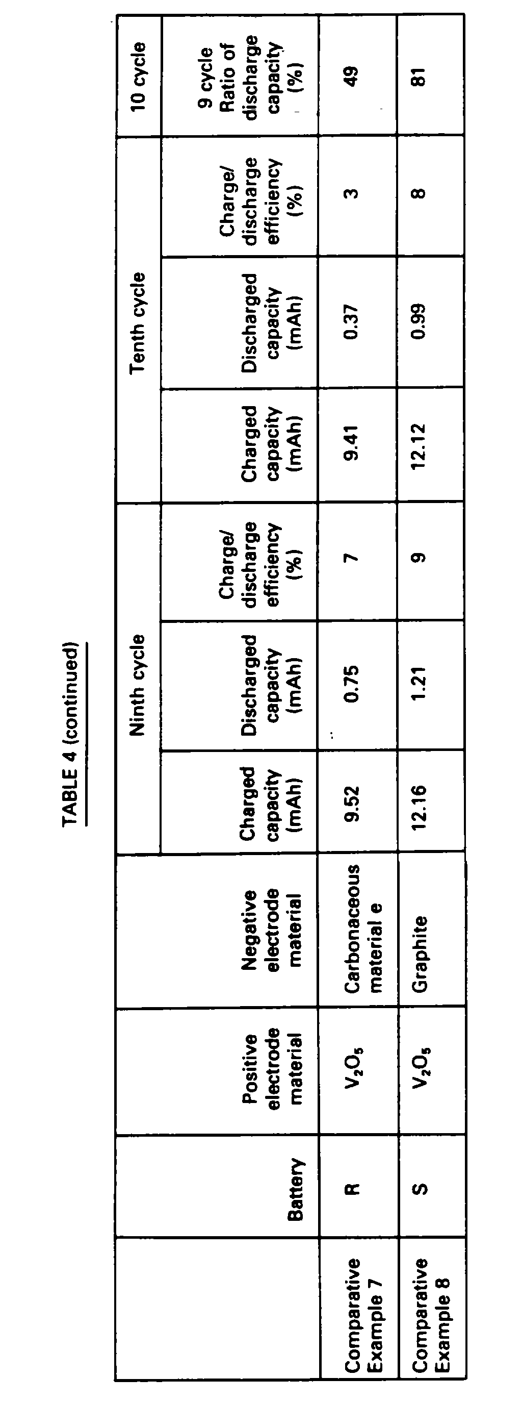
- (i) In the same manner as in the above (a), usual charge/discharge was carried out up to the ninth cycle and then self-discharge test was carried out at the tenth cycle. That is, at the tenth cycle, discharge after completion of charging was carried out after preservation at 25°C for 30 days.
- In Table 4, charging capacities, discharging capacities and charge/discharge efficiencies at which discharging was immediately carried out at the ninth cycle and at which discharging was carried out at the tenth cycle after preservation for 30 days and a ratio (%) of discharging capacity at the tenth cycle to the ninth cycle of each of the batteries are shown.

- (ii) In the same manner as in the above (i), usual charge/discharge was carried out up to the forth cycle and then self-discharge test was carried out at the fifth cycle. That is, at the tenth cycle, discharge after completion of charging was carried out after preservation at 25°C for 30 days.
- In Table 5, charging capacities, discharging capacities and charge/discharge efficiencies at which discharging was immediately carried out at the forth cycle and at which discharging was carried out at the fifth cycle after preservation for 30 days and a ratio (%) of discharging capacity at the fifth cycle to the forth cycle of each of the batteries are shown.


- As clearly seen from the description as mentioned above, the secondary battery using a non-aqueous solvent of the present invention using a carbonaceous material having the specific structure for the negative electrode has extremely excellent charge/discharge cycle characteristics as compared with those used a conventional graphite as the negative electrode material and those used a carbonaceous material deviated from the requirements of the present invention, and is less in self-discharge and excellent in preservability whereby its industrial value is extremely great.
Claims (10)
- A secondary battery using a non-aqueous solvent comprising a positive electrode capable of being re-charged and constituted by a metallic chalcogen compound, an electrolytic solution which comprises an electrolyte dissolved in the non-aqueous solvent, and a negative electrode capable of being re-charged which comprises a powder of a carbonaceous material obtained by the carbonization of at least one of a high molecular weight linear novolac resin, a condensed polycyclic hydrocarbon compound and a polycyclic heterocyclic compound, and having a pseudographite structure, which structure, if it were to be subjected to further progress of carbonisation, would be converted to graphite, an atomic ratio of hydrogen/carbon of not more than 0.10, a spacing of (002) planes as determined by X-ray wide-angle diffraction of 3.37-3.68 Å, a crystallite size in the direction of the c axis of 12 Å to 150 Å, a distance a₀ twice the spacing d₁₁₀ of the (110) planes measured by X-ray wide angle diffraction of 2.38 Å to less than 2.46 Å and a crystallite size in the direction of the a axis, La, of 10 Å to 70 Å.
- A secondary battery using a non-aqueous solvent according to claim 1, wherein the battery has a laminated structure of said positive electrode and said negative electrode through a separator impregnated with an electrolyte.
- A secondary battery using a non-aqueous solvent according to claim 1, wherein said electrolyte is a combination of an alkali metal cation and at least one anion selected from ClO4 -, PF6 -, BF4 -, CF₃SO3 - and AsF6 -; or a quaternary ammonium salt.
- A secondary battery using a non-aqueous solvent according to claim 1, wherein said negative electrode comprises a carbonaceous material having a spacing of (002) planes, d₀₀₂ as determined by X-ray wide angle diffraction of 3.39 Å - 3.68 Å and a crystallite size in the direction of the c axis, Lc, of 12 Å to 100 Å.
- A secondary battery using a non-aqueous solvent according to claim 4, wherein said negative electrode comprises a carbonaceous material having an atomic ratio of hydrogen/carbon of not more than 0.07, a d₀₀₂ of 3.41 Å to 3.68 Å and an Lc of 12 Å to 70 Å.
- A secondary battery using a non-aqueous solvent according to claim 5, wherein said negative electrode comprises a carbonaceous material having an La of 15 Å to 70 Å and an a₀ of 2.39 Å to less than 2.46 Å.
- A secondary battery using a non-aqueous solvent according to claim 1, wherein said metallic chalcogen compound is selected from Cr₃O₈, V₂O₅, V₆O₁₃, LiCoO₂, MoO₃, WO₃, TiS₂, V₂S₅, MoS₂, MoS₃, CuS, Fe0.25V0.75S₂, Cr0.25V0.75S₂, Cr0.5V0.5S₂, Na0.1CrS₂, NiPS₃, FePS₃, VSe₂ and NbSe₃.
- A secondary battery using a non-aqueous solvent according to claim 1, wherein the discharging capacity of the positive electrode is set 1.1-fold or more to that of the negative electrode.
- A secondary battery using a non-aqueous solvent according to claim 1, wherein said carbonaceous material is previously doped with an alkali metal cation.
- A secondary battery using a non-aqueous solvent according to claim 1, wherein said chalcogen compound is previously doped with an alkali metal cation.
Applications Claiming Priority (4)
| Application Number | Priority Date | Filing Date | Title |
|---|---|---|---|
| JP92438/85 | 1985-04-30 | ||
| JP92437/85 | 1985-04-30 | ||
| JP9243885 | 1985-04-30 | ||
| JP9243785 | 1985-04-30 |
Publications (3)
| Publication Number | Publication Date |
|---|---|
| EP0201038A1 EP0201038A1 (en) | 1986-11-12 |
| EP0201038B1 EP0201038B1 (en) | 1990-07-18 |
| EP0201038B2 true EP0201038B2 (en) | 1996-01-24 |
Family
ID=26433858
Family Applications (1)
| Application Number | Title | Priority Date | Filing Date |
|---|---|---|---|
| EP86105951A Expired - Lifetime EP0201038B2 (en) | 1985-04-30 | 1986-04-30 | Secondary battery using non-aqueous solvent |
Country Status (4)
| Country | Link |
|---|---|
| US (1) | US4702977A (en) |
| EP (1) | EP0201038B2 (en) |
| CA (1) | CA1275437C (en) |
| DE (1) | DE3672671D1 (en) |
Cited By (1)
| Publication number | Priority date | Publication date | Assignee | Title |
|---|---|---|---|---|
| US6294147B1 (en) | 1999-07-14 | 2001-09-25 | Nbt Gmbh | Ternary lithium manganese spinel and process for the production thereof |
Families Citing this family (53)
| Publication number | Priority date | Publication date | Assignee | Title |
|---|---|---|---|---|
| EP0205856B1 (en) * | 1985-05-10 | 1991-07-17 | Asahi Kasei Kogyo Kabushiki Kaisha | Secondary battery |
| US4863814A (en) * | 1986-03-27 | 1989-09-05 | Sharp Kabushiki Kaisha | Electrode and a battery with the same |
| JPS63124372A (en) * | 1986-11-11 | 1988-05-27 | Sharp Corp | Nonaqueous electrolyte battery |
| US4945014A (en) * | 1988-02-10 | 1990-07-31 | Mitsubishi Petrochemical Co., Ltd. | Secondary battery |
| JP2718696B2 (en) * | 1988-06-08 | 1998-02-25 | シャープ株式会社 | Electrode |
| JP2674793B2 (en) * | 1988-08-31 | 1997-11-12 | ソニー 株式会社 | Non-aqueous electrolyte battery |
| US5028500A (en) * | 1989-05-11 | 1991-07-02 | Moli Energy Limited | Carbonaceous electrodes for lithium cells |
| US5162170A (en) * | 1989-07-21 | 1992-11-10 | Mistubishi Petrochemical Co., Ltd. | Electrode for secondary battery |
| ATE105975T1 (en) * | 1989-07-29 | 1994-06-15 | Sony Corp | CARBON MATERIAL AND A NON-AQUEOUS ELECTROCHEMICAL CELL USING SUCH MATERIAL. |
| JP2592152B2 (en) * | 1989-12-19 | 1997-03-19 | シャープ株式会社 | Method for producing carbon electrode for non-aqueous lithium secondary battery |
| CA2043472A1 (en) * | 1990-06-04 | 1991-12-05 | Mitsutaka Miyabayashi | Electrode for secondary battery |
| US5153082A (en) * | 1990-09-04 | 1992-10-06 | Bridgestone Corporation | Nonaqueous electrolyte secondary battery |
| CA2052317C (en) * | 1990-09-28 | 1995-09-26 | Norio Takami | Nonaqueous electrolyte secondary battery |
| US5130211A (en) * | 1990-10-24 | 1992-07-14 | Her Majesty The Queen In Right Of The Provence Of British Columbia | Electrolyte solution sequestering agents for electrochemical cells having carbonaceous electrodes |
| DE69127251T3 (en) * | 1990-10-25 | 2005-01-13 | Matsushita Electric Industrial Co., Ltd., Kadoma | Non-aqueous electrochemical secondary battery |
| US5521027A (en) * | 1990-10-25 | 1996-05-28 | Matsushita Electric Industrial Co., Ltd. | Non-aqueous secondary electrochemical battery |
| US5244757A (en) * | 1991-01-14 | 1993-09-14 | Kabushiki Kaisha Toshiba | Lithium secondary battery |
| DE4101533A1 (en) * | 1991-01-19 | 1992-07-23 | Varta Batterie | ELECTROCHEMICAL SECONDARY ELEMENT |
| JP2643035B2 (en) * | 1991-06-17 | 1997-08-20 | シャープ株式会社 | Carbon negative electrode for non-aqueous secondary battery and method for producing the same |
| JPH05101818A (en) * | 1991-08-07 | 1993-04-23 | Mitsubishi Gas Chem Co Inc | Carbon molding for negative electrode and lithium secondary battery |
| CA2083001C (en) | 1991-12-17 | 1996-12-17 | Yuzuru Takahashi | Lithium secondary battery using a non-aqueous solvent |
| US5484669A (en) * | 1991-12-27 | 1996-01-16 | Matsushita Electric Industrial Co., Ltd. | Nonaqueous electrolyte secondary batteries |
| EP0563988B1 (en) * | 1992-04-02 | 1997-07-16 | Fuji Photo Film Co., Ltd. | Nonaqueous secondary battery |
| EP0601832B1 (en) * | 1992-12-07 | 1999-05-19 | Honda Giken Kogyo Kabushiki Kaisha | Alkaline ion-absorbing/desorbing carbon material, electrode material for secondary battery using the carbon material and lithium battery using the electrode material |
| US5510212A (en) * | 1993-01-13 | 1996-04-23 | Delnick; Frank M. | Structural micro-porous carbon anode for rechargeable lithium ion batteries |
| JP3653105B2 (en) * | 1993-02-25 | 2005-05-25 | 呉羽化学工業株式会社 | Carbonaceous material for secondary battery electrode |
| JP3188032B2 (en) | 1993-03-30 | 2001-07-16 | 三洋電機株式会社 | Lithium secondary battery |
| US5426006A (en) * | 1993-04-16 | 1995-06-20 | Sandia Corporation | Structural micro-porous carbon anode for rechargeable lithium-ion batteries |
| CA2098248C (en) * | 1993-06-11 | 1999-03-16 | Jeffrey Raymond Dahn | Electron acceptor substituted carbons for use as anodes in rechargeable lithium batteries |
| FR2708383A1 (en) * | 1993-07-27 | 1995-02-03 | Accumulateurs Fixes | Method for lithiation of an anode of carbon-containing material for a rechargeable electrochemical generator |
| EP0646978B1 (en) * | 1993-09-03 | 1997-12-29 | Kureha Kagaku Kogyo Kabushiki Kaisha | Carbonaceous electrode material for secondary battery and process for production thereof |
| US5571638A (en) * | 1993-09-30 | 1996-11-05 | Sumitomo Chemical Company Limited | Lithium secondary battery |
| CA2114902C (en) | 1994-02-03 | 2001-01-16 | David S. Wainwright | Aqueous rechargeable battery |
| JP3419119B2 (en) * | 1994-11-15 | 2003-06-23 | 日本電池株式会社 | Non-aqueous electrolyte secondary battery |
| JP2885654B2 (en) * | 1994-12-06 | 1999-04-26 | 科学技術振興事業団 | Method for producing nitrogen-containing carbon material |
| GB2296125B (en) * | 1994-12-16 | 1998-04-29 | Moli Energy | Pre-graphitic carbonaceous insertion compounds and use as anodes in rechargeable batteries |
| EP0726606B1 (en) * | 1995-02-09 | 2002-12-04 | Kureha Kagaku Kogyo Kabushiki Kaisha | Carbonaceous electrode material for battery and process for production thereof |
| JP3581474B2 (en) * | 1995-03-17 | 2004-10-27 | キヤノン株式会社 | Secondary battery using lithium |
| DE69605362T2 (en) * | 1995-07-03 | 2000-06-21 | Gen Motors Corp | Process for the production of deactivated carbon-containing anodes |
| CA2158242C (en) * | 1995-09-13 | 2000-08-15 | Qiming Zhong | High voltage insertion compounds for lithium batteries |
| US5750288A (en) * | 1995-10-03 | 1998-05-12 | Rayovac Corporation | Modified lithium nickel oxide compounds for electrochemical cathodes and cells |
| AU1147597A (en) * | 1995-12-07 | 1997-06-27 | Sandia Corporation | Methods of preparation of carbon materials for use as electrodes in rechargeable batteries |
| US5677082A (en) * | 1996-05-29 | 1997-10-14 | Ucar Carbon Technology Corporation | Compacted carbon for electrochemical cells |
| US5874166A (en) * | 1996-08-22 | 1999-02-23 | Regents Of The University Of California | Treated carbon fibers with improved performance for electrochemical and chemical applications |
| WO2001071834A2 (en) | 2000-03-20 | 2001-09-27 | Fitter Johan C | Method and apparatus for achieving prolonged battery life |
| US9391325B2 (en) * | 2002-03-01 | 2016-07-12 | Panasonic Corporation | Positive electrode active material, production method thereof and non-aqueous electrolyte secondary battery |
| JP3723140B2 (en) * | 2002-03-04 | 2005-12-07 | Necトーキン株式会社 | Power storage device using quinoxaline compound |
| JP5171113B2 (en) * | 2007-05-30 | 2013-03-27 | 富士重工業株式会社 | Method for manufacturing power storage device |
| JP5262119B2 (en) * | 2008-01-10 | 2013-08-14 | ソニー株式会社 | Negative electrode and battery |
| EP2506349A4 (en) * | 2009-11-25 | 2014-05-07 | Sumitomo Bakelite Co | Carbon material for lithium ion secondary battery, negative electrode material for lithium ion secondary battery, and lithium ion secondary battery |
| JP5657348B2 (en) * | 2010-11-04 | 2015-01-21 | Jx日鉱日石エネルギー株式会社 | Carbon material for negative electrode of lithium ion secondary battery and non-aqueous secondary battery using the same |
| US20130202920A1 (en) * | 2012-02-07 | 2013-08-08 | Battelle Memorial Institute | Dendrite-Inhibiting Salts in Electrolytes of Energy Storage Devices |
| US20180287153A1 (en) * | 2015-09-30 | 2018-10-04 | Kuraray Co., Ltd. | Carbonaceous material for sodium ion secondary battery negative electrode, and sodium ion secondary battery using carbonaceous material for sodium ion secondary battery negative electrode |
Family Cites Families (5)
| Publication number | Priority date | Publication date | Assignee | Title |
|---|---|---|---|---|
| JPS5835881A (en) * | 1981-08-27 | 1983-03-02 | Kao Corp | Electrochemical cell |
| DE3215126A1 (en) * | 1982-04-23 | 1983-10-27 | Robert Bosch Gmbh, 7000 Stuttgart | STORAGE ELEMENT FOR ELECTRICAL ENERGY |
| US4615960A (en) * | 1984-01-19 | 1986-10-07 | Kanebo, Ltd. | Insoluble and infusible substrate with a polyacene-type skeletal structure, and its applications for electrical conductor or organic cell |
| JPH0789483B2 (en) * | 1984-05-07 | 1995-09-27 | 三洋化成工業株式会社 | Secondary battery |
| EP0165047B1 (en) * | 1984-06-12 | 1997-10-15 | Mitsubishi Chemical Corporation | Secondary batteries containing electrode material obtained by pyrolysis |
-
1986
- 1986-04-24 US US06/855,826 patent/US4702977A/en not_active Expired - Lifetime
- 1986-04-29 CA CA000507871A patent/CA1275437C/en not_active Expired - Lifetime
- 1986-04-30 EP EP86105951A patent/EP0201038B2/en not_active Expired - Lifetime
- 1986-04-30 DE DE8686105951T patent/DE3672671D1/en not_active Expired - Lifetime
Cited By (1)
| Publication number | Priority date | Publication date | Assignee | Title |
|---|---|---|---|---|
| US6294147B1 (en) | 1999-07-14 | 2001-09-25 | Nbt Gmbh | Ternary lithium manganese spinel and process for the production thereof |
Also Published As
| Publication number | Publication date |
|---|---|
| DE3672671D1 (en) | 1990-08-23 |
| CA1275437C (en) | 1990-10-23 |
| US4702977A (en) | 1987-10-27 |
| EP0201038A1 (en) | 1986-11-12 |
| EP0201038B1 (en) | 1990-07-18 |
Similar Documents
| Publication | Publication Date | Title |
|---|---|---|
| EP0201038B2 (en) | Secondary battery using non-aqueous solvent | |
| EP0165047B1 (en) | Secondary batteries containing electrode material obtained by pyrolysis | |
| US5176969A (en) | Electrode for secondary battery | |
| EP0549802B1 (en) | Electrode for secondary battery | |
| US4980250A (en) | Secondary battery | |
| EP0627777B1 (en) | Non-aqueous liquid electrolyte secondary battery | |
| KR100776523B1 (en) | Non-aqueous electrolyte secondary cell | |
| JPS62122066A (en) | Nonaqueous solvent battery | |
| JPH05286763A (en) | Electrode material | |
| JPH05101818A (en) | Carbon molding for negative electrode and lithium secondary battery | |
| EP0601832A1 (en) | Alkaline ion-absorbing/desorbing carbon material, electrode material for secondary battery using the carbon material and lithium battery using the electrode material | |
| EP0647974B1 (en) | Lithium secondary battery | |
| JP3410757B2 (en) | Electrode material | |
| JP3113057B2 (en) | Manufacturing method of electrode material | |
| JPH0782836B2 (en) | Electrode material | |
| JPH06187988A (en) | Improved nonaqueous solvent lithium secondary battery | |
| JP3212662B2 (en) | Non-aqueous solvent secondary battery | |
| JP3973170B2 (en) | Lithium ion secondary battery and method for producing electrode for lithium secondary battery | |
| JP3322962B2 (en) | Alkali ion adsorption / desorption material | |
| JP3291758B2 (en) | Non-aqueous solvent secondary battery and its electrode material | |
| JP3519462B2 (en) | Lithium secondary battery | |
| EP0791972B1 (en) | Lithium secondary battery | |
| JPH01274360A (en) | Secondary battery | |
| JPH05290888A (en) | Nonaqueous solvent secondary battery | |
| JPH09106818A (en) | Manufacture of negative electrode for non-aqueous electrolyte secondary battery |
Legal Events
| Date | Code | Title | Description |
|---|---|---|---|
| PUAI | Public reference made under article 153(3) epc to a published international application that has entered the european phase |
Free format text: ORIGINAL CODE: 0009012 |
|
| AK | Designated contracting states |
Kind code of ref document: A1 Designated state(s): DE FR GB NL |
|
| 17P | Request for examination filed |
Effective date: 19870422 |
|
| 17Q | First examination report despatched |
Effective date: 19880812 |
|
| GRAA | (expected) grant |
Free format text: ORIGINAL CODE: 0009210 |
|
| AK | Designated contracting states |
Kind code of ref document: B1 Designated state(s): DE FR GB NL |
|
| ET | Fr: translation filed | ||
| REF | Corresponds to: |
Ref document number: 3672671 Country of ref document: DE Date of ref document: 19900823 |
|
| PLBE | No opposition filed within time limit |
Free format text: ORIGINAL CODE: 0009261 |
|
| PLBI | Opposition filed |
Free format text: ORIGINAL CODE: 0009260 |
|
| PLAA | Information modified related to event that no opposition was filed |
Free format text: ORIGINAL CODE: 0009299DELT |
|
| 26N | No opposition filed | ||
| 26 | Opposition filed |
Opponent name: KARL LEBLING INGENIEURBUERO Effective date: 19910418 Opponent name: ASAHI CHEMICAL INDUSTRY CO., LTD. Effective date: 19910418 |
|
| NLR1 | Nl: opposition has been filed with the epo |
Opponent name: KARL LEBLING INGENIEURBUERO. Opponent name: ASAHI CHEMICAL INDUSTRY CO., LTD. |
|
| PUAH | Patent maintained in amended form |
Free format text: ORIGINAL CODE: 0009272 |
|
| STAA | Information on the status of an ep patent application or granted ep patent |
Free format text: STATUS: PATENT MAINTAINED AS AMENDED |
|
| 27A | Patent maintained in amended form |
Effective date: 19960124 |
|
| AK | Designated contracting states |
Kind code of ref document: B2 Designated state(s): DE FR GB NL |
|
| NLR2 | Nl: decision of opposition | ||
| ET3 | Fr: translation filed ** decision concerning opposition | ||
| NLR3 | Nl: receipt of modified translations in the netherlands language after an opposition procedure | ||
| REG | Reference to a national code |
Ref country code: GB Ref legal event code: IF02 |
|
| PGFP | Annual fee paid to national office [announced via postgrant information from national office to epo] |
Ref country code: GB Payment date: 20040414 Year of fee payment: 19 |
|
| PGFP | Annual fee paid to national office [announced via postgrant information from national office to epo] |
Ref country code: NL Payment date: 20040415 Year of fee payment: 19 |
|
| PGFP | Annual fee paid to national office [announced via postgrant information from national office to epo] |
Ref country code: DE Payment date: 20040427 Year of fee payment: 19 |
|
| PGFP | Annual fee paid to national office [announced via postgrant information from national office to epo] |
Ref country code: FR Payment date: 20050411 Year of fee payment: 20 |
|
| PG25 | Lapsed in a contracting state [announced via postgrant information from national office to epo] |
Ref country code: GB Free format text: LAPSE BECAUSE OF NON-PAYMENT OF DUE FEES Effective date: 20050430 |
|
| PG25 | Lapsed in a contracting state [announced via postgrant information from national office to epo] |
Ref country code: NL Free format text: LAPSE BECAUSE OF NON-PAYMENT OF DUE FEES Effective date: 20051101 Ref country code: DE Free format text: LAPSE BECAUSE OF NON-PAYMENT OF DUE FEES Effective date: 20051101 |
|
| GBPC | Gb: european patent ceased through non-payment of renewal fee |
Effective date: 20050430 |
|
| NLV4 | Nl: lapsed or anulled due to non-payment of the annual fee |
Effective date: 20051101 |